
RS500i - Loudspeaker SoundTube - Free user manual and instructions
Find the device manual for free RS500i SoundTube in PDF.


| Product Type | In-ceiling speaker |
| Brand | SoundTube |
| Model | RS500i |
| Dimensions (Diameter x Depth) | 9.5 in x 4.2 in (241 mm x 107 mm) |
| Weight | 2.8 kg (6.2 lb) |
| Power Handling (RMS) | 60 W |
| Impedance | 8 ohms |
| Frequency Response | 55 Hz - 20 kHz |
| Sensitivity | 88 dB SPL (1W/1m) |
| Mounting Type | Ceiling mount with dog ears |
| Cutout Size | 8.2 in (208 mm) diameter |
| Recommended Amplifier Power | 30 - 120 W per channel |
| Driver Configuration | 1 x 5.25 in polypropylene woofer, 1 x 0.75 in silk dome tweeter |
| Input Type | Spring-loaded terminals |
| Grille | White perforated steel, paintable |
| Operating Environment | Indoor, dry location only |
| Cleaning Instructions | Wipe with a dry, soft cloth. Do not use abrasive cleaners or water. |
| Safety Precautions | Disconnect power before installation. Ensure secure mounting. Do not expose to moisture or extreme temperatures. |
| Replaceable Parts | Grille, mounting dogs (screws and brackets) |
| Warranty | 5 years limited (check SoundTube official policy) |
Frequently Asked Questions - RS500i SoundTube
User questions about RS500i SoundTube
0 question about this device. Answer the ones you know or ask your own.
Ask a new question about this device
Download the instructions for your Loudspeaker in PDF format for free! Find your manual RS500i - SoundTube and take your electronic device back in hand. On this page are published all the documents necessary for the use of your device. RS500i by SoundTube.
USER MANUAL RS500i SoundTube
Install Instructions For:
RS4-EZ, RS400i, RS500i, HP590i, RS600i, HP690i, RS800i, RS1201i, HP890i, RS1001i-II, HP129a, & HP1290i speakers

1.435.647.9555
800.647.TUBE
www.soundtube.com
RS400i, RS500i, RS600i, RS800i, RS1001i-II, HP690i and HP890i - UL listed 1480 ©2008 SoundTube Entertainment, Inc. All rights reserved. PN INS-RSI Rev 11.12.18

Warning
SoundTube speakers must be installed by a professional audio installer/contractor. For safety and for optimum audio performance, installer must follow all directions issued by SoundTube Entertainment.

Warning
Do not spec or install speaker near support beam, ventilation duct or other structure that may interfere with speaker function or dispersion.
natural_image
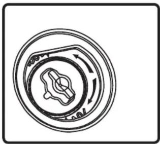
Circular mechanical component diagram with directional arrows, no text or symbols present- Select the tap position by removing the rubber plug on grille to access rotary switch. Switch is preset to maximum tap setting in 70.7 V mode. Select desired setting and reinsert rubber plug. Note: The grille-mounted tap switch cover is keyed; be sure flat edge of plug lines up with flat edge of hole in grille.
natural_image
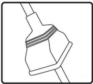
Pure mechanical component diagram without any text, numbers, or symbols- Slip terminal weather boot over signal wire. For environmental applications, put RTV silicone around nipple and base when installation is complete.

natural_image
Diagram of a hand using a tool to connect two electrical connectors with rotation arrows (no text or symbols)- Connect signal wire to 4-pin Euroblock plug. Tighten unused terminal screws. Use inside positive and negative inputs for either voice coil or distributed systems. For daisy chaining, use outside positive and negative terminals.
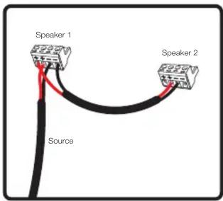
- When daisy chaining, wire the outside terminals to the inside terminals of the next speaker. This step only applies to tap settings using the transformer and not when the speaker is used on bypass.
natural_image
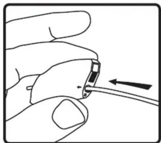
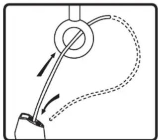
Hand holding a small electronic component with an arrow indicating direction (no text or symbols)- Thread hanging or safety cable through SpeedClamp™ mechanisms as shown.
natural_image
Diagram of a mechanical or fluidic device with curved and dashed lines indicating motion or flow (no text or symbols)- Attach the hanging cable by securing it and safety cable to structure as shown.

natural_image
Line drawing of a hand holding a tool with a circular component, no text or symbols present- Thread cable end(s) through SpeedClamp ™ mechanisms as shown.

natural_image
Illustration of a hand holding a medical or surgical tool with tubing and arrows indicating force direction (no text or symbols)- Adjust speaker hanging height with SpeedClamp™ mechanism. Pull to tighten & insert release key (small hex wrench) into SpeedClamp™ as shown to loosen or adjust.

natural_image
Line drawing of a hand using scissors to cut or mark a small object on a circular base (no text or symbols)- Attach hanging cable to the center hole in the speaker hanging bracket.

natural_image
Line drawing of a hand using scissors to cut or mark a small object on a circular base (no text or symbols)- Attach the safety cable to one of the secondary holes in the hanging bracket.

natural_image
Technical line drawing of a mechanical assembly with no visible text or symbols- Insert 4-pin Euroblock plug into Euroblock jack on rear of speaker. Connectors are keyed for polarity.
natural_image
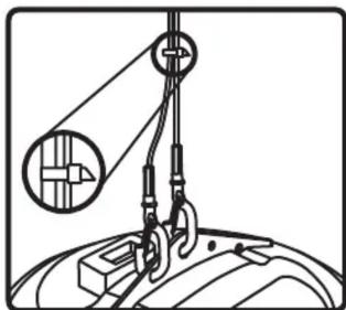
Diagram of a pulley system lifting a car wheel, showing rope routing and mechanical components (no text or labels)- Use zip or twist-lock ties to secure safety cable & signal wire to main hanging cables. Cable cover available for asthetic applications (SLT-10).
Brand : SoundTube
Model : RS500i
Category : Loudspeaker