
Switchbone V2 - Guitar effect pedal Radial Engineering - Free user manual and instructions
Find the device manual for free Switchbone V2 Radial Engineering in PDF.


| Product Type | Active ABY Switcher / 3-Channel Guitar Switcher |
| Dimensions | 5.5 x 3.5 x 2.0 inches (140 x 89 x 51 mm) |
| Weight | 1.5 lbs (0.68 kg) |
| Power Supply | 9V DC (center negative, 100mA min) adapter or 9V battery |
| Number of Channels | 3 (Channel A, Channel B, Mute) |
| Ground Lift | Yes, per channel via switch |
| Phase Reverse | Yes, global switch |
| Input Impedance | 500 kOhms |
| Output Impedance | 100 Ohms |
| Frequency Response | 20 Hz - 20 kHz (+/- 0.5 dB) |
| Signal to Noise Ratio | >90 dB |
| Construction | 14-gauge steel chassis, powder-coated finish |
| Inputs | 1 x 1/4" TS instrument input |
| Outputs | 2 x 1/4" TS (A & B) + 1 x 1/4" TS mute output |
| Switching Type | True bypass (relay-based) |
| LED Indicators | Yes, per channel (red/green) |
| Additional Features | Buffer on/off switch, Mute with tuner out, Drag control load correction |
| Included Accessories | Quick start guide, 9V DC adapter (optional), Velcro mounting kit |
| Warranty | 3 years limited |
| Maintenance & Cleaning | Wipe with dry cloth; avoid solvents. Keep jacks clean with contact cleaner. |
| Safety | Use only recommended power supply. Do not expose to moisture. |
| Spare Parts & Repairability | Contact Radial Engineering for authorized service. Common parts available via distributor. |
Frequently Asked Questions - Switchbone V2 Radial Engineering
User questions about Switchbone V2 Radial Engineering
0 question about this device. Answer the ones you know or ask your own.
Ask a new question about this device
Download the instructions for your Guitar effect pedal in PDF format for free! Find your manual Switchbone V2 - Radial Engineering and take your electronic device back in hand. On this page are published all the documents necessary for the use of your device. Switchbone V2 by Radial Engineering.
USER MANUAL Switchbone V2 Radial Engineering
Only connect electrical equipment that is properly grounded with a 3-prong AC plug. Older amps with 2-prong plugs should be serviced before using them with any amp switcher. An improperly grounded amp can be a very dangerous thing and never should be used in multi-amp setups.
Radial Engineering takes no responsibility for how the Switchbone V2 is connected or used. It is the user's full responsibility to ensure that proper electrical connections are maintained on all equipment connected to the Switchbone V2 and that proper building electrical codes have been followed wherever the Switchbone V2 is used.
Note that damage to the Switchbone V2 or other connected equipment caused by improper wiring or improperly grounded equipment is not covered under the warranty.
RADIAL SWITCHBONE • V2 USER GUIDE
Table of Contents Page
Introduction....1
Features and Functions....2-3
Overview 4-5
Making Connections....6
Standard ABY Setup....7-8
Adding a Tuner or Third Amp....8-9
Baseline Buffer 10
Power Booster....10-11
Slingshot Remote 12
Slingshot Internal Jumpers....13
Block Diagram....14-15
Safety Information 16
Specifications 17
Warranty ....Back Cover
Thank you for purchasing the Radial Switchbone V2™. We are confident that once you get to know the extended feature set, you will come to appreciate the power and control that is now underfoot! This being said, the Switchbone V2 is both easy to use, yet featured-packed. So before you start plugging in, please take the time to read through this manual. Not only will it help you get the most out of it, it will save you time later when trying to figure out new setups.
After your reading session, if you find yourself wondering about features that are not well explained or simply have a question, visit Radial's web site and visit the FAQ page. This is where we post questions from users and updates. You can also post a question and we will do our best to reply in short order. Now get ready to enjoy what is likely the most powerful, flexible and cleanest sounding switcher you have ever tried.
FEATURES
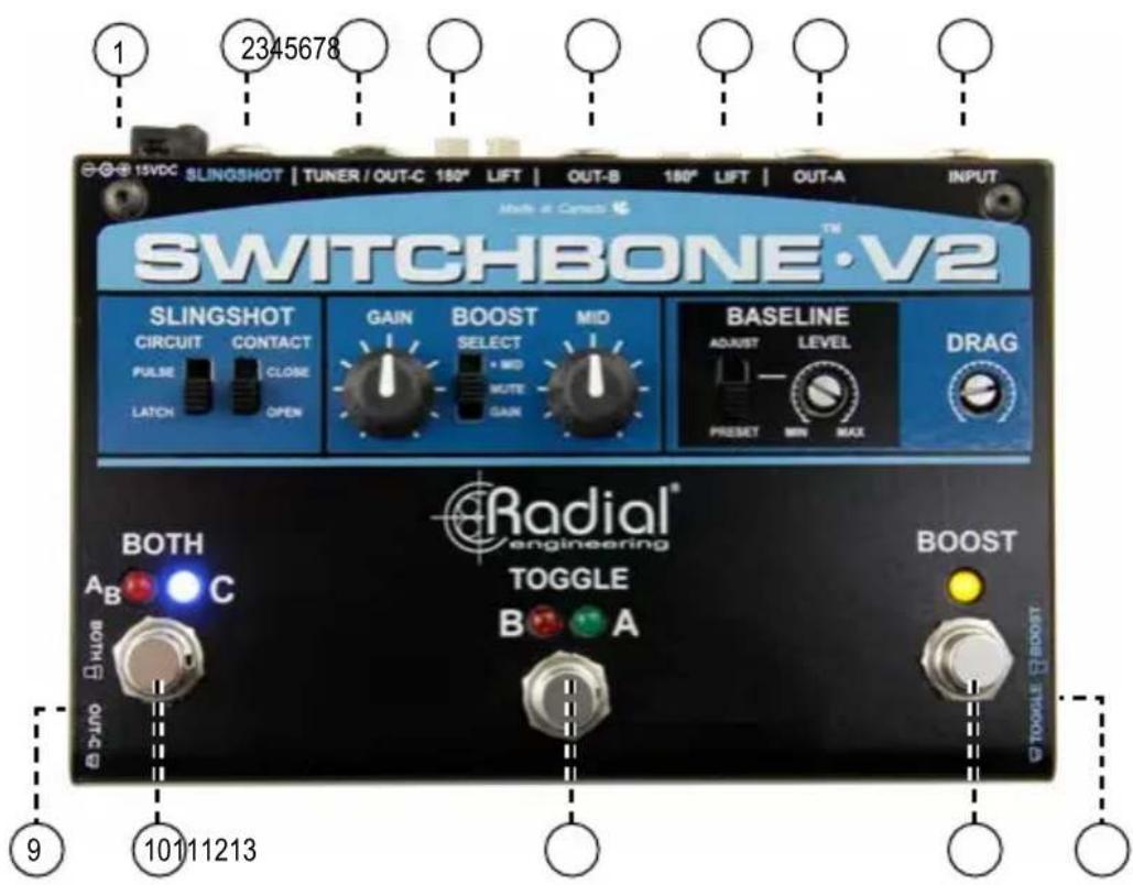
- 15VDC: Connection for the power supply.
- SLINGSHOT: Contact closure output used to activate external devices.
- TUNER/OUT-C: Isolated 14 " output used to feed a tuner or a 3rd guitar amplifier.
- 180°: Polarity reverse switch, used to phase-align OUT-B and C.
- OUT-B: Isolated 14 " output used to feed the signal to your second guitar amplifier.
- LIFT: Ground lift switch used to eliminate hum and buzz.
- OUT-A: Direct 14 " output used to feed your primary amplifier.
- INPUT: Standard 14 " input used to connect your guitar to the Switchbone V2.
- BOTH / OUT-C: Recessed switch sets the footswitch function to either activate both A and B amps, or turn on amp C.
- BOTH: Footswitch used to activate both A and B amps, or turn on amp C.
- TOGGLE: Footswitch used to select between amps A or B.
- BOOST: Footswitch used to activate the power booster.
- TOGGLE / BOOST: Recessed switch to select which footswitch is used to activate external devices via the SLINGSHOT.
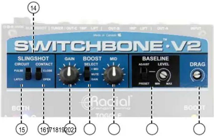
- SLINGSHOT CIRCUIT: Lets you send a on-off type command to external devices via a 14 " cable. The Slingshot may be activated using the BOOST or the TOGGLE footswitches.
- CIRCUIT: Sets the Slingshot to latching or pulse modes.
- CONTACT: Sets the Slingshot contact closure to normally open or normally closed.
- GAIN: Sets the boost output level from 0dB to +18dB.
- SELECT: Assigns the BOOST footswitch to MUTE, GAIN only or GAIN + MID boost.
- MID: Variable control, delivers up to 12dB of mid boost for soloing.
- ADJUST / PRESET: Selects buffer between the unity gain setting or the user-adjustable level.
- DRAG: Variable control is used to set the load that is applied on the pickup from 22K to 1 Meg.
WARNING
Only connect electrical equipment that is properly grounded with a 3-prong AC plug. Older amps with 2-prong plugs should be serviced before using them with any amp switcher. An improperly grounded amp can be a very dangerous thing and never should be used in multi-amp setups.
Radial Engineering takes no responsibility for how the Switchbone V2 is connected or used. It is the user's full responsibility to ensure that proper electrical connections are maintained on all equipment connected to the Switchbone V2 and that proper building electrical codes have been followed wherever the Switchbone V2 is used.
Note that damage to the Switchbone V2 or other connected equipment caused by improper wiring or improperly grounded equipment is not covered under the warranty.
OVERVIEW
The Switchbone V2 is a multi-purpose buffer, switcher, power booster and performance enhancer all in one. The best way to approach it is to break each section down into modules and then bring them together in your mind to suit your setup.

flowchart
graph LR
    A["GUITAR"] --> B["BUFFER"]
    B --> C["MOOD"]
    C --> D["MID BOOST"]
    D --> E["OUT-A"]
    D --> F["OUT-B"]
    D --> G["OUT-C (TUNER)"]
    C --> H["REMOTE"]
    H --> D
Input buffer and Drag control

In order to minimize switching noise and signal loss, the Switchbone V2 is active. In other words, it employs a buffer to amplify and manage the signal before the switching occurs. To
minimize artefact and harshness, a 100% discrete class-A buffer is employed. This is augmented with Drag™ control load correction to allow the guitarist to precisely adjust the load on the pickup for the most natural tone. A Baseline™ level control lets you increase the buffer drive circuit to hit your amp harder or compensate for extra long cables. This is particularly effective when using older amplifiers that do not have input and master level controls.
Power booster

Most guitarists use a combination of pedals including various distortion or overdrive pedals for rhythm and lead. As the Switchbone V2 will likely be the last pedal in the chain, the addition of a power booster enables the player to solo using
any combination of pedals. A mid boost may also be engaged to add, sustain or fatten up the sound of a single coil pickup. Should the power booster not be required, the footswitch can be repurposed to mute the signal for quiet on-stage tuning via the separate tuner output.
Output section


The Switchbone V2 may be used as a typical ABY switcher or configured to drive three amps simultaneously by re-purposing the tuner out to feed a third amp. In ABY mode, the center footswitch is used to select the active amp, while the left footswitch is used to turn them both on. Depressing a set & forget switch reassigns the BOTH footswitch
to activate the Tuner/OUT-C. Outputs B and C are transformer isolated to eliminate hum and buzz caused by ground loops.
Slingshot remote control

Just imagine... being able to switch amps while activating a rackmount digital delay or in-amp spring reverb. Slingshot™ is a contact closure system that works with all kinds of devices to let you perform various tasks using a single foot-stomp. Add devices such as the Headbone™ head switcher or Cabbage™ cabinet switcher to change channels, heads
or cabinets on the fly. With the Twinline™, you can even share pedals between your two amp's effects loops and have your pedalboard 'move' when you switch amps. The Switchbone V2 is designed to give you more control than ever before.
MAKING CONNECTIONS
Before making connections, always ensure the volume levels on your amps are turned off as this will avoid power-on and plug-in transients that could reduce the lifespan of your speakers and other sensitive components. Connect the included 15VDC power supply to the Switchbone V2. There is no power switch, as soon as power is connected, you will see one of the LED's illuminate and it will spring to life. The Switchbone V2 is equipped with a cable lock to secure the power supply into place. Simply loosen the hex screw and pass the power cable through the clamp in a compact loop.

natural_image
Close-up of a black audio jack with multiple knobs and a close-up inset showing a hand holding a cable (no visible text or symbols)Set all of the controls and switches to the start position:

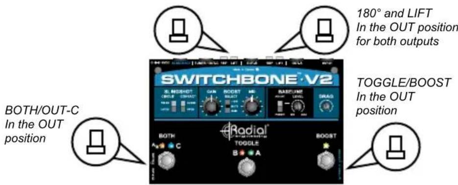
IMPORTANT
OUT-A is your primary output and should always be used. It should be connected to an amp that is properly grounded with a three prong U-ground for safety. Never remove the safety ground on your amp as this is both illegal and there to protect you from an electrical shock. Please consult your local electrical authority or qualified electronic technician for more details.
STANDARD ABY SETUP
To test the signal path, connect your guitar to the INPUT and OUT-A to your main amp. Check to make sure the OUT-A LED is illuminated. Turn up your guitar and then turn up your amp slowly to ensure the signal is passing. You can now connect your second amp and test by toggling between the two amps using the middle AB footswitch. For fun, combine both amps using the BOTH footswitch.
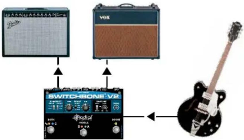
You will note that when you hit the BOTH footswitch, one of the LEDs will begin to flash. This TOGGLE mode function is designed to let you know in advance what will happen when you hit the BOTH footswitch again whereby the flashing LED will be the one that goes off. You can toggle the flashing LED by depressing the AB selector footswitch so that when you return to single amp playing, you can ensure the amp that you want on will be the one that is active.

Example:
When amp 1 is on, the channel A LED next to the TOGGLE switch will be lit.
Depress the BOTH switch and the 2nd channel is now activated. The new channel LED will flash.
Hit the TOGGLE footswitch and the flashing LED will toggle between the two channels.
To go back to single channel operation, depress the BOTH switch again and the flashing channel will go off.
When both amps are on, there are two things to watch for... the first is noise, the second is phase. If you hear noise, try depressing the ground lift switch on OUT-B. This works in conjunction with the isolation transformers to eliminate hum and buzz caused by ground loops. This lifts the audio ground, not the electrical safety ground.
When using two different amplifiers, these will often be out of phase whereby one amp will be pushing the speaker forward while the other will be pushing it backwards. This causes phase cancellation that is most noticeable in the low end and can make the amps sound distant. To test, face your two amps together (speaker to speaker) and listen. Try depressing the 180° polarity reverse switch on OUT-B to hear the difference.

ADDING A TUNER OR THIRD AMP
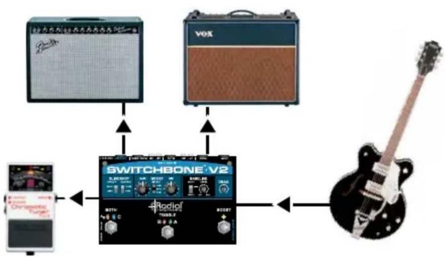
You can add a tuner to your setup using the dedicated TUNER out. This output is both buffered and transformer isolated to ensure clocking noise from the tuner is not audible in the guitar signal path. This also permits the tuner out to be reassigned as a third amp when required.
flowchart
graph TD
    A["扬声器"] --> B["Switch"]
    C["VOX"] --> B
    D["Radio1/200Hz"] --> B
    E["扬声器"] --> F["Switch"]
    G["电感器"] --> H["Switch"]
    I["电感器"] --> J["Switch"]
    B --> K["Radio1/200Hz"]
    K --> L["电感器"]
    L --> M["Radio1/200Hz"]
    M --> N["电感器"]
    N --> O["Radio1/200Hz"]
    O --> P["电感器"]
    P --> Q["Radio1/200Hz"]
    Q --> R["电感器"]
    R --> S["Radio1/200Hz"]
    S --> T["电感器"]
    T --> U["Radio1/200Hz"]
    U --> V["电感器"]
    V --> W["Radio1/200Hz"]
    W --> X["电感器"]
    X --> Y["Radio1/200Hz"]
    Y --> Z["电感器"]
    Z --> AA["Radio1/200Hz"]
    AA --> AB["电感器"]
    AB --> AC["Radio1/200Hz"]
    AC --> AD["电感器"]
    AD --> AE["Radio1/200Hz"]
    AE --> AF["电感器"]
    AF --> AG["Radio1/200Hz"]
    AG --> AH["电感器"]
    AH --> AI["Radio1/200Hz"]
    AI --> AJ["电感器"]
    AJ --> AK["Radio1/200Hz"]
    AK --> AL["电感器"]
    AL --> AM["Radio1/200Hz"]
    AM --> AN["电感器"]
    AN --> AO["Radio1/200Hz"]
    AO --> AP["电感器"]
    AP --> AQ["Radio1/200Hz"]
    AQ --> AR["电感器"]
    AR --> AS["Radio1/200Hz"]
    AS --> AT["电感器"]
    AT --> AU["Radio1/200Hz"]
    AU --> AV["电感器"]
    AV --> AW["Radio1/200Hz"]
    AW --> AX["电感器"]
    AX --> AY["Radio1/200Hz"]
    AY --> AZ["电感器"]
    AZ --> BA["Radio1/200Hz"]
    BA --> BB["电感器"]
    BB --> BC["Radio1/200Hz"]
    BC --> BD["电感器"]
    BD --> BE["Radio1/200Hz"]
    BE --> BF["电感器"]
    BF --> BG["Radio1/200Hz"]
    BG --> BH["电感器"]
    BH --> BI["Radio1/200Hz"]
    BI --> BJ["电感器"]
    BJ --> BK["Radio1/200Hz"]
    BK --> BL["电感器"]
    BL --> BM["Radio1/200Hz"]
    BM --> BN["电感器"]
    BN --> BO["Radio1/200Hz"]
    BO --> BP["电感器"]
    BP --> BQ["Radio1/200Hz"]
    BQ --> BR["电感器"]
    BR --> BS["Radio1/200Hz"]
    BS --> BT["电感器"]
    BT --> BU["Radio1/200Hz"]
    BU --> BV["电感器"]
    BV --> BW["Radio1/200Hz"]
    BW --> BX["电感器"]
    BX --> BY["Radio1/200Hz"]
    BY --> BZ["电感器"]
    BZ --> CA["Radio1/200Hz"]
    CA --> CB["电感器"]
    CB --> CC["Radio1/200Hz"]
    CC --> CD["电感器"]
    CD --> CE["Radio1/200Hz"]
    CE --> CF["电感器"]
    CF --> CG["Radio1/200Hz"]
    CG --> CH["电感器"]
    CH --> CI["Radio1/200Hz"]
    CI --> CJ["电感器"]
    CJ --> CK["Radio1/200Hz"]
    CK --> CR["电感器"]
    CR --> CS["Radio1/200Hz"]
    CS --> CT["电感器"]
    CT --> CU["Radio1/200Hz"]
    CU --> CV["电感器"]
    CV --> CW["Radio1/200Hz"]
    CW --> CX["电感器"]
    CX --> CY["Radio1/200Hz"]
    CY --> CZ["电感器"]

When the BOTH/OUT-C set & forget switch is in the OUT position, the Switchbone V2 is configured like a typical ABY switcher. In this mode, the tuner output is always on. When the BOTH/OUT-C switch is pushed inwards, it changes the BOTH function to add OUT-C so that no signal will be present on TUNER/OUT-C unless the footswitch is depressed. When used for a third amp, you should check for noise and phase following the steps detailed above. Always use Amp-A as the reference for phase.

flowchart
graph TD
    A["Speaker with antenna"] --> B["Switchbone V2"]
    C["VOX"] --> B
    D["Radioled Voice"] --> B
    E["Radioled Audio System"] --> B
    B --> F["Output to Electric Guitar"]
DRAG CONTROL LOAD CORRECTION
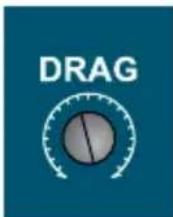
Drag is used to set the load that is being applied on the pickup. We noticed early on that pickups sound quite different depending on the type of amp or buffering circuit to which they are connected. Drag lets you set the load to match your personal setup and deliver a tone to your amp that sounds as if you are connected directly. Set the DRAG control to 12 o'clock and then rotate the control using a guitar pick as a screwdriver. Turning the control clockwise will brighten the tone while turning it counter-clockwise will darken it. Adjust to suit.
It is important to note that Drag will only work when used with regular magnetic pickups and true-bypass pedals. In other words, the load that is applied to your pickup will be established by the first buffer in line. Once the signal is buffered, other buffers down the line will have little or no effect. The Bigshot EFX™ dual effects loop router provides a great cost effective solution if you would like to bypass pedals that don't feature true bypass themselves.
BASELINE BUFFER
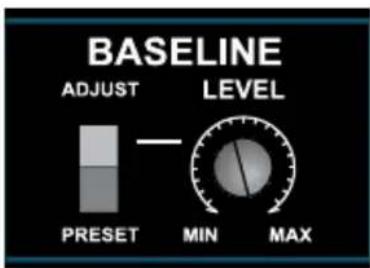
The Baseline™ buffers the signal, lowering noise by lowering the impedance. High impedance circuits are much more susceptible to picking up stray magnetic fields and radio frequencies. Once the signal is buffered, you can essentially drive the cable a much longer distance when using a quality coaxial cable.
The Baseline buffer circuit inside the Switchbone V2 is the very same one used in our top-of-the-line Radial JD7 Injector™. This is not made using integrated circuits with thousands of transistors and huge amounts of negative feedback to compensate. Instead, individual (discrete) transistors are carefully deployed in a Class-A configuration to deliver a precise gain stage while eliminating as much negative feedback in the circuit as possible. The resulting tone is pure, clean and natural sounding.
A selector switch allows the Switchbone V2 buffer to be set to unity gain when in the bottom PRE-SET position or it may be adjusted to suit when pushed up to the VARIABLE position. This Baseline setting can be used to drive the front end of your amp harder for extra kick. This is particularly effective when using older vintage amps that often do not have sensitivity and drive controls.
Start by listening to the pre-set Baseline level. This is set to unity gain to deliver the same output level as whatever guitar signal is sent in. Move the slider switch to ADJUST and start by setting the Baseline fully counter-clockwise. Try increasing the level by slowly turning using a guitar pick as a screwdriver. You will notice your amp will break up a little sooner. The Baseline is able to drive your amp with an extra +12db of gain... so be careful... too much of a good thing may lead to unwanted distortion!
POWER BOOSTER

Having a power booster at the end of your signal chain lets you turn any setting on your pedalboard into solo mode. You could be playing rhythm with slight crunch, a chorus and a delay and then, with a single foot stomp, elevate the output for a lead passage.
The Switchbone V2 power booster is activated by depressing the right BOOST footswitch. This works in conjunction with a 3-position footswitch SELECT switch, a variable clean boost control and a mid boost control. To use the clean boost, set the 3-position switch in the bottom to GAIN and adjust the boost level to suit. This is able to deliver up to +18dB of pure, Class-A clean gain. Setting the select to the top +MID position lets you then add more mid-range to your solos. This is particularly effective at increasing sustain or fattening up single coil pickups.
When the SELECT switch is moved to the middle MUTE position, the two boost circuits are disabled and boost footswitch will mute the amplifier outputs for quiet on-stage tuning. It should be noted that the tuner output is always on. This allows quick checks in between songs.
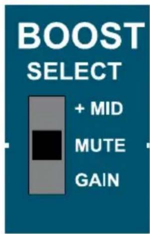
+ MID: Mid boost and gain boost. This is the most often used setting. This allows both gain and mid to be boosted as needed. Simply adjust the boost level and away you go.
MUTE: Disengages the boost function and turns this into a mute switch. This allows you to monitor the tuner output without having any sound pass through to the output of the Switchbone V2. Be careful! This is usually the first place to look if you are not getting any sound out of your Switchbone V2!
GAIN: This bypasses the MID function and directs the signal through a GAIN boost. The gain boost is used to increase sustain for soloing.

line
| Hz | dB | | ---- | ----- | | 20 | 0.0 | | 50 | 0.0 | | 100 | 0.0 | | 200 | 0.0 | | 500 | 0.0 | | 1k | 0.0 | | 2k | 0.0 | | 5k | 0.0 | | 10k | 0.0 | | 2k | 0.0 | | 5k | 0.0 | | 10k | 0.0 | | 2k | 0.0 | | 5k | 0.0 | | 10k | 0.0 | | 2k | 0.0 | | 5k | -2.5 | | 10k | -7.5 | | 2k | -12.5 | | 5k | -12.5 | | 10k | -12.5 | | 2k | -7.5 | | 5k | -2.5 | | 10k | 0.0 |SLINGSHOT REMOTE

The idea behind the Slingshot™ remote system was to cause something extra to happen simultaneously when making a setup change. For example, to switch from amp-A to amp-B with a single foot action, maybe change an effects processor. Another example could be switching from one channel to another on a vintage Twin Reverb®, and having the reverb go on or off automatically. Slingshot is basically a contact closure whereby when a connection is made using a standard 1/4" guitar cable, a remote action can be triggered. With Slingshot™ equipped devices like the Headbone™ or Cabbone™, you can remotely toggle heads, cabinets or even move pedalboards around using the Twinline™.
Connecting is as simple as plugging in a guitar. There are two selector switches that let you configure the circuit. The CONTACT lets you determine if the circuit is normally open or normally closed. This would for instance turn the remote device on or off depending on where it is set. The CIRCUIT switch lets you set the Slingshot in a LATCH mode for old school amps or PULSE mode for newer amps. Simply discuss the setup options with your dealer or the manufacturer to find out what setting would work best with your intended setup.
The Slingshot remote output may be activated using either the BOOST footswitch or the AB toggle footswitch. This is determined using a recessed set & forget switch adjacent to the boost footswitch. When set in the outwards position to BOOST, depressing the BOOST footswitch will cause the Slingshot to trigger. When set inwards to TOGGLE, when you toggle between amps A and B, it will fire. Hitting the BOOST or the TOGGLE footswitch again will cause the Slingshot to return to normal or off.

flowchart
graph TD
    A["Switchbone V2"] -->|Ch1Ch2Reverb ON/OFF| B["Ch1Ch2Reverb"]
    B --> C["Radiof"]
    C --> D["Radiof"]
Example: When the Slingshot is set to activate on the TOGGLE it will allow you to turn on the reverb on the amp when you switch between channels.
The Switchbone V2 has internal jumpers as an added feature to give further control of what footswitch sends the signal to another device. To access the internal jumpers remove the top shell to expose the board.

You will see the jumper in the default position on the far right labeled OUT-B. This will allow the Slingshot to be activated either on the TOGGLE or BOOST depending on the position of the recessed switch.
When using in ABY configuration
When using the Switchbone V2 as an ABY switcher, where the BOTH footswitch activates amps A and B simultaneously, you can set the Slingshot output to send a signal when the BOTH footswitch is activated. To do so, move the internal jumper to the left position labeled BOTH.
When using in AB/C configuration
When you have three amps connected to the Switchbone V2, and the BOTH footswitch activates amp C, you can set the Slingshot output to send a signal when you activate the third amp with the BOTH footswitch. To configure the Switchbone V2 in this way, move the internal jumper to the middle position labeled OUT-C. Note that if you change back to an ABY setup with only two amps, you will need to change this jumper again for the Slingshot output to work.
Switchbone ABC Block Diagram

flowchart
graph LR
    A["INPUT"] --> B["BUFFER"]
    B --> C["GAIN PRESET"]
    C --> D["ASSIGN"]
    D --> E["GAIN BOOST"]
    E --> F["MID BOOST"]
    F --> G["BOOST SELECT"]
    G --> H["BOOST"]
    H --> I["OUT C"]
    I --> J["PHASE REV OUT C"]
    I --> K["PHASE REV OUT B"]
    I --> L["SLINGSHOT"]
    M["DRAG"] --> B
    N["POCKET"] --> O["TOGGLE"]
    P["AND"] --> Q["AND + RED MUTE CAN ONLY"]
    R["AND"] --> S["AND + RED MUTE CAN ONLY"]
    T["AND"] --> U["AND + RED MUTE CAN ONLY"]
    V["AND"] --> W["AND + RED MUTE CAN ONLY"]
    X["AND"] --> Y["AND + RED MUTE CAN ONLY"]
    Z["AND"] --> AA["AND + RED MUTE CAN ONLY"]
    AB["OUT A"] --> AC["OUT B"]
    AD["OUT B"] --> AE["OUT C"]
    AF["OUT C"] --> AG["OUT B"]
    AH["POCKET"] --> AI["POCKET"]
    AJ["POCKET"] --> AK["POCKET"]
    AL["POCKET"] --> AM["POCKET"]
    AN["POCKET"] --> AO["POCKET"]
    AP["PRESS OUT B"] --> AQ["SLOWSHOT"]
Switchbone ABY Block Diagram

flowchart
graph LR
    INPUT --> BUFFER
    BUFFER --> GAIN_PRESET
    GAIN_PRESET --> GAIN_BOOST
    GAIN_BOOST --> MID_BOOST
    MID_BOOST --> BOOST_SELECT
    BOOST_SELECT --> BOOST
    OUTPUT_A --> OUT_B
    OUT_B --> OUT_B_OUT_A
    OUTPUT_B_OUT_A --> OUT_B_OUT_B
    OUTPUT_B_OUT_A --> OUT_B_OUT_C
    OUTPUT_B_OUT_C --> OUT_B_OUT_D
    OUTPUT_B_OUT_D --> OUT_B_OUT_E
    OUTPUT_B_OUT_E --> OUT_B_OUT_F
    OUTPUT_B_OUT_F --> OUT_B_OUT_GND Lift
    OUTPUT_B_OUT_GND Lift --> OUT_B_OUT_H
    OUTPUT_B_OUT_H --> OUT_B_OUT_I
    OUTPUT_B_OUT_I --> OUT_B_OUT_V
    OUTPUT_B_OUT_V --> OUT_B_OUT_R
    OUTPUT_B_OUT_R --> OUT_B_OUT_S
    OUTPUT_B_OUT_S --> OUT_B_OUT_T
    OUTPUT_B_OUT_T --> OUT_B_OUT_U
    OUTPUT_B_OUT_U --> OUT_B_OUT_V
    OUTPUT_B_OUT_V --> OUT_B_OUT_W
    OUTPUT_B_OUT_W --> OUT_B_OUT_X
    OUTPUT_B_OUT_X --> OUT_B_OUT_Y
    OUTPUT_B_OUT_Y --> OUT_B_OUT_Z
    OUTPUT_B_OUT_Z --> OUT_B_OUT_A
    OUTPUT_B_OUT_A --> OUT_B_OUT_V
    OUTPUT_B_OUT_V --> OUT_B_OUT_W
    OUTPUT_B_OUT_W --> OUT_B_OUT_X
    OUTPUT_B_OUT_X --> OUT_B_OUT_Y
    OUTPUT_B_OUT_Y --> OUT_B_OUT_Z
    OUTPUT_B_OUT_Z --> OUT_B_OUT_V
    OUTPUT_B_OUT_V --> OUT_B_OUT_W
    OUTPUT_B_OUT_W --> OUT_B_OUT_X
    OUTPUT_B_OUT_X --> OUT_B_OUT_Y
    OUTPUT_B_OUT_Y --> OUT_B_OUT_Z
    OUTPUT_B_OUT_Z --> OUT_B_OUT_V
    OUTPUT_B_OUT_V --> OUT_B_OUT_W
    OUTPUT_B_OUT_W --> OUT_B_OUT_X
    OUTPUT_B_OUT_X --> OUT_B_OUT_Y
    OUTPUT_B_OUT_Y <--> PHASE_REV_GND_LIFT
    PHASE_REV_GND_LIFT --> PHASE_REV_TUNER
    PHASE_REV_TUNER --> PHASE_REV_GND_LIFT
    PHASE_REV_GND_LIFT --> PHASE_REV_SLINGSHOT
    PHASE_REV_GND_LIFT --> PHASE_REV_PRESS_OUT_B
    PHASE_REV_GND_LIFT --> PHASE_REV_PRESS_OUT_B
    PHASE_REV_GND_LIFT --> PHASE_REV_PRESS_OUT_B
    PHASE_REV_GND_LIFT --> PHASE_REV_PRESS_OUT_B
    PHASE_REV_GND_LIFT --> PHASE_REV_PRESS_OUT_B
    PHASE_REV_GND_LIFT --> PHASE_REV_PRESS_OUT_B
    PHASE_REV_GND_LIFT --> PHASE_REV_PRESOLUTOUT_A
    PHASE_REV_GND_LIFT --> PHASE_REV_PRESOLUTOUT_B
    PHASE_REV_GND_LIFT --> PHASE_REV_PRESOLUTOUT_C
    PHASE_REV_GND_LIFT --> PHASE_REV_PRESOLUTOUT_D
    PHASE_REV_GND_LIFT --> PHASE_REV_PRESOLUTOUT_E
    PHASE_REV_GND_LIFT --> PHASE_REV_PRESOLUTOUT_F
    PHASE_REV_GND_LIFT --> PHASE_REV_PRESOLUTOUT_G
    PHASE_REV_GND_LIFT --> PHASE_REV_PRESOLUTOUT_H
    PHASE_REV_GND_LIFT --> PHASE_REV_PRESOLUTOUT_I
    PHASE_REV_GND_LIFT --> PHASE_REV_PRESOLUTOUT_J
    PHASE_REV_GND_LIFT --> PHASE_REV_PRESOLUTOUT_K
    PHASE_REV_GND_LIFT --> PHASE_REV_PRESOLUTOUT_L
    PHASE_REV_GND_LIFT --> PHASE_REV_PRESOLUTOUT_M
    PHASE_REV_GND_LIFT --> PHASE_REV_PRESOLUTOUT_N
    PHASE_REV_GND_LIFT --> PHASE_REV_PRESOLUTOUT_O
    PHASE_REV_GND_LIFT --> PHASE_REV_PRESOLUTOUT_P
    PHASE_REV_GND_LIFT --> PHASE_REV_PRESOLUTOUT_Q
    PHASE_REV_GND_LIFT --> PHASE_REV_PRESOLUTOUT_Q_1
    PHASE_REV_GND_LIFT --> PHASE_REV_PRESOLUTOUT_Q_2
    PHASE_REV_GND_LIFT --> PHASE_REV_PRESOLUTOUT_Q_3
    PHASE_REV_GND_LIFT --> PHASE_REV_PRESOLUTOUT_Q_4
    PHASE_REV_GND_LIFT --> PHASE_REV_PRESOLUTOUT_Q_5
    PHASE_REV_GND_LIFT --> PHASE_REV_PRESOLUTOUT_Q_6
    PHASE_REV_GND_LIFT --> PHASE_REV_PRESOLUTOUT_Q_7
    PHASE_REV_GND_LIFT --> PHASE_REV_PRESOLUTOUT_Q_8
    PHASE_REV_GND_LIFT --> PHASE_REV_PRESOLUTOUT_Q_9
    PHASE_REV_GND_LIFT --> PHASE_REV_PRESOLUTOUT_Q_10
    PHASE_REV_GND_LIFT --> PHASE_REV_PRESOLUTOUT_Q_11
    PHASE_REV_GND_LIFT --> PHASE_REV_PRESOLUTOUT_Q_12
    PHASE_REV_GND_LIFT --> PHASE_REV_PRESOLUTOUT_Q_13
    PHASE_REV_GND_LIFT --> PHASE_REV_PRESOLUTOUT_Q_14
    PHASE_REV_GND_LIFT --> PHASE_REV_PRESOLUTOUT_Q_15
    PHASE_REV_GND_LIFT --> PHASE_REV_PRESOLUTOUT_Q_16
    PHASE]{PORCE}
IMPORTANT
OUT-A is your primary output and should always be used. It should be connected to an amp that is properly grounded with a three prong U-ground for safety. Never remove the safety ground on your amp as this is both illegal and there to protect you from an electrical shock. Please consult your local electrical authority or qualified electronic technician for more details.
WARNING
Only connect electrical equipment that is properly grounded with a 3-prong AC plug. Older amps with 2-prong plugs should be serviced before using them with any amp switcher. An improperly grounded amp can be a very dangerous thing and never should be used in multi-amp setups.
Radial Engineering takes no responsibility for how the Switchbone V2 is connected or used. It is the user's full responsibility to ensure that proper electrical connections are maintained on all equipment connected to the Switchbone V2 and that proper building electrical codes have been followed wherever the Switchbone V2 is used.
Note that damage to the Switchbone V2 or other connected equipment caused by improper wiring or improperly grounded equipment is not covered under the warranty.
SPECIFICATIONS
Circuit Type: Discrete Class-A
Input Impedance: ....Variable with drag control
Load Correction: ....Drag control variable load
Output Impedance: 10k Ohm
Noise Floor: -111dB
Output-1: Class-A buffered, direct
Output-2: Class-A buffered, transformer isolated
Tuner/Output-3: Class-A buffered, transformer isolated
Slingshot Remote Output: ....Latch or pulse (selectable)
Baseline Gain: ____ Unity to +12dB
Boost Level: ......Variable to +19dB
Mid-Boost: 0 to +13dB @650Hz
Switching: ..... Opto-coupler assisted, 5msec rise time
LED Indicators: ....Large 3mm OD ultra-bright LED's
Ground Lift: Output-B and Tuner/Output-C
Polarity Reverse: 180° (phase) reverse at Output-B and Tuner/Output-C
Construction: 14 gauge steel, baked enamel finish
Size: 6.75 x 4.625 x 1.75" (171 x 117 x 44mm)
Weight: 2.35lb (1.06kg)
Warranty: Radial 3-year, transferable
THREE YEAR TRANSFERABLE LIMITED WARRANTY
RADIAL ENGINEERING LTD. ("Radial") warrants this product to be free from defects in material and workmanship and will remedy any such defects free of charge according to the terms of this warranty. Radial will repair or replace (at its option) any defective component(s) of this product (excluding finish and wear and tear on components under normal use) for a period of three (3) years from the original date of purchase. In the event that a particular product is no longer available, Radial reserves the right to replace the product with a similar product of equal or greater value. In the unlikely event that a defect is uncovered, please call 1-800-939-1001 or email service@radialeng.com to obtain a RA number (Return Authorization number) before the 3 year warranty period expires. The product must be returned prepaid in the original shipping container (or equivalent) to Radial or to an authorized Radial repair center and you must assume the risk of loss or damage. A copy of the original invoice showing date of purchase and the dealer name must accompany any request for work to be performed under this limited and transferable warranty. This warranty shall not apply if the product has been damaged due to abuse, misuse, misapplication, accident or as a result of service or modification by any other than an authorized Radial repair center.
THERE ARE NO EXPRESSED WARRANTIES OTHER THAN THOSE ON THE FACE HEREOF AND DESCRIBED ABOVE. NO WARRANTIES WHETHER EXPRESSED OR IMPLIED, INCLUDING BUT NOT LIMITED TO, ANY IMPLIED WARRANTIES OF MERCHANTABILITY OR FITNESS FOR A PARTICULAR PURPOSE SHALL EXTEND BEYOND THE RESPECTIVE WARRANTY PERIOD DESCRIBED ABOVE OF THREE YEARS. RADIAL SHALL NOT BE RESPONSIBLE OR LIABLE FOR ANY SPECIAL, INCIDENTAL OR CONSEQUENTIAL DAMAGES OR LOSS ARISING FROM THE USE OF THIS PRODUCT. THIS WARRANTY GIVES YOU SPECIFIC LEGAL RIGHTS, AND YOU MAY ALSO HAVE OTHER RIGHTS, WHICH MAY VARY DEPENDING ON WHERE YOU LIVE AND WHERE THE PRODUCT WAS PURCHASED.
To meet the requirements of California Proposition 65, it is our responsibility to inform you of the following:
WARNING: This product contains chemicals known to the State of California to cause cancer, birth defects or other reproductive harm.
Please take proper care when handling and consult local government regulations before discarding.
All trademarks belong to their respective owners. All references to these are for example only and are not associated with Radial Engineering Ltd.

www.radialeng.com
Made in Canada
Radial Engineering Ltd.
1165 - 1845 Kingsway Ave, Port Coquitlam BC V3C 1S9
tel: 604-942-1001 • fax: 604-942-1010
info@radialeng.com • www.radialeng.com

- RADIAL SWITCHBONE • V2 USER GUIDE
- Table of Contents Page
- WARNING
- OVERVIEW
- Input buffer and Drag control
- Power booster
- Output section
- Slingshot remote control
- MAKING CONNECTIONS
- IMPORTANT
- STANDARD ABY SETUP
- Example:
- ADDING A TUNER OR THIRD AMP
- DRAG CONTROL LOAD CORRECTION
- BASELINE BUFFER
- SLINGSHOT REMOTE
- When using in ABY configuration
- When using in AB/C configuration
- SPECIFICATIONS
- THREE YEAR TRANSFERABLE LIMITED WARRANTY
- - 1845 Kingsway Ave, Port Coquitlam BC V3C 1S9
Brand : Radial Engineering
Model : Switchbone V2
Category : Guitar effect pedal