
MRA 90 - Receiver INFINITY - Free user manual and instructions
Find the device manual for free MRA 90 INFINITY in PDF.


| Product Type | Receiver |
| Brand | Infinity |
| Model | MRA 90 |
| Dimensions (W x H x D) | 430 x 88 x 310 mm |
| Weight | 4.5 kg |
| Power Supply | 220-240 V AC, 50/60 Hz |
| Power Consumption | 25 W (standby < 0.5 W) |
| Supported Audio Formats | MP3, WMA, AAC, FLAC |
| Supported Video Formats | MPEG-2, MPEG-4, H.264 |
| Connectivity | HDMI, USB, Optical, Coaxial, Ethernet |
| Wireless | Wi-Fi 802.11 b/g/n, Bluetooth 4.2 |
| Remote Control | Included |
| Main Functions | Radio, media player, streaming, amplifier |
| Cleaning and Maintenance | Wipe with dry cloth, avoid liquids |
| Safety Features | Overheat protection, automatic shutdown |
| Spare Parts and Repairability | Contact authorized service center; power cord available as spare |
| General Information | Operating temperature: 0-40°C; humidity: 20-80% |
Frequently Asked Questions - MRA 90 INFINITY
User questions about MRA 90 INFINITY
0 question about this device. Answer the ones you know or ask your own.
Ask a new question about this device
Download the instructions for your Receiver in PDF format for free! Find your manual MRA 90 - INFINITY and take your electronic device back in hand. On this page are published all the documents necessary for the use of your device. MRA 90 by INFINITY.
USER MANUAL MRA 90 INFINITY
The Infinity MRA-150 Mobile Reference Amplifier is a technologically advanced electronic component using modern circuit technology and State-of-the-Art components. It represents the culmination of years of intensive research and development in auto stereo design, employing circuit concepts found only in the highest quality home audio components.
Although the MRA-150 is designed to install quickly and easily, we urge you not to begin this installation before you have read this owner's manual in its entirety. A few moments taken now may save time and possible problems later on.
Also, please read the label adhered to the bottom of the amplifier for it contains important information.
Keep this manual in a safe place for future reference.
Precautions
- Choose a location with adequate ventilation. The preferred location is either in the trunk or rear of a hatchback. Install the amplifier forward within the trunk so it does not get wet when the trunk lid is open. Do not install the amplifier in a location where it can be reached by direct sunlight.
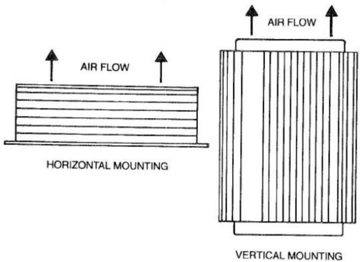
- Do not drape wires over the heat sink as this will diminish air flow. Also, keep objects away from the amplifier to allow for unrestricted air flow.
- Keep the heat sinks clean by wiping with a soft, clean cloth every few months. This will prevent dirt from building up on the heat sink fins which could restrict air flow, reducing the effectiveness of the heat sink.
- Mount the amplifier to a strong, solid surface to prevent it coming loose in the event of a sudden stop or accident.
- The MRA-150 will generate a certain amount of heat, especially when playing very loud. This is normal and should not be of concern. If the amplifier should generate heat beyond its proper operating range, a thermal protector will shut it off until it cools down.
- If the amplifier behaves abnormally after it is installed—or at any time thereafter, turn it off immediately and try to locate the problem (faulty or incorrect wiring, a short circuit, loose connection, etc.). If you cannot locate the source of the problem, do not continue to operate the amplifier. Contact your dealer at once for advice. Under no circumstances should you attempt to play the MRA-150 if it continues to cycle—or turns off completely.
- The MRA-150 is designed for use in any vehicle with a 12 volt negative ground system. If your auto was produced prior to 1966, especially if it was produced in Europe, discuss the matter with your dealer before installation is made. Installing the MRA-150 into an auto with a positive ground system could result in severe damage to your stereo as well as to the auto's electrical system. If you are in doubt regarding this precaution, check with your dealer and have him inspect your vehicle.
- The use of high quality speakers is mandatory if you wish to obtain definitive results from the MRA-150. Ask your dealer about the new Infinity CS-1 component speaker system as well as the other Infinity models produced for super-high quality sound reproduction.
- If you play your music very loud and use multiple speaker systems, it is recommended to bi-amplify your systems using one MRA-150 for the bass and another for the midrange and highs. This arrangement will provide all the power required for any type of program material even at extremely loud levels.
Features
- Adjustable input levels
• Tightly regulated, pulse width modulated power supply
• Automatic shut-off/recycle circuits protect against:
Dead batteries — amp shuts off if car battery voltage drops below 10 bolts
Short circuits in speaker hookup — no speaker fuses to replace
Thermal overload — sensors prevent amp from overheating
• Made in U.S.A.
• Warranty: 1 year, parts and labor (see complete warranty statement).
A technically competent person can successfully install the MRA-150 without difficulty. If you are not one of these people, you should consult a competent and experienced installer to do the work.
If performing the installation yourself, be sure you have the necessary tools to complete the work (screw drivers, drill, bits, soldering iron, non-corrosive solder, tape, felt marker pen, etc.). Choose a location where there is adequate ventilation from every direction. There must be at least six inches of headroom above the heat sinks to permit sufficient air flow. The heat sink fins must face upward and must never be inverted (with fins facing down) or mounted at an oblique angle. This will restrict air flow causing excessive heat to build which will turn the amplifier off.
Be careful to place the amplifier in a position where mounting screws will not protrude through the metalwork where they can puncture the gas tank, gas line, wiring or other critical parts of your car.
Using the amplifier as a mounting template, place it in the location where it is to be mounted. Take a felt tipped marking pen and insert the pen through the four amplifier mounting holes and mark the location of these holes on the surface of the metal trunk floor or wall. Tap and drill the holes, being very careful not to drill too steep (which might touch gas lines, wiring, gas tank, etc.). Install the amplifier using the hardware-supplied. Tighten the screws carefully so they are not stripped.
NOTE: The black, heavy gauge wire (#12) is used to ground the amplifier to the auto metalwork. The black wire may be attached to any of the four mounting screws—or a separate hole may be drilled specifically for this purpose. In either case, be sure that the ground is fastened to a metal part of your car and that the area around the screw is scraped free of paint and is absolutely clean. The ground contact must be secure and must not shake free.
Always drill the mounting hole using a bit that is smaller in radius than the mounting screw. This will result in a tight fit.
Wiring
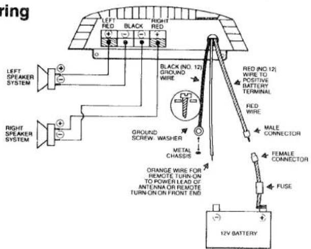
CAUTION: DO NOT CONNECT THE POSITIVE LEAD (B+) TO THE CAR'S BATTERY UNTIL THE ENTIRE INSTALLATION HAS BEEN COMPLETED AND CHECKED OUT.
Never run wires underneath (outside of) your car. Road dirt, salt and other corrosives might eat through the insulation causing shorts and/or intermittent operation. Wiring should be positioned underneath carpeting or in the side panels. To minimize interference which could create noise and other disturbances, run the power cables along the opposite side.
If it is necessary to run the cables through cutouts (especially with sharp edges), be sure to tape the wire along the section that goes through the hole. Use cable clamps whenever possible and add stress relief loops in several sections along the wire path to prevent the wiring from stretching or breaking.
Do not install the wiring permanently until you are certain the system is operating correctly.
Connect the output of your AM/FM cassette front end to the left and right inputs on the amplifier. If the front end has a preamp output, then the connection to the amplifier can be made merely by connecting a high quality, shielded lead to the left and right inputs of the amplifier. If there is no preamp output on your front end, it will be necessary to use an attenuation box (available at your dealer) to drop the high level output taken from the speaker output of the AM/FM cassette front end before they are connected to the inputs of the power amplifier. This will prevent overloading of the amplifier's input stages.
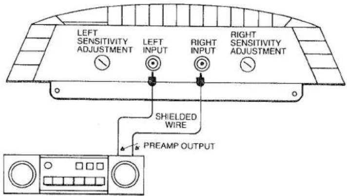
STEREO FRONT END
When connecting the AM/FM cassette front end to the amplifier using the preamp output on the front end, it is always necessary to use shield wire to make this connection because the signal is subject to hum and noise pickup. If the signal is taken directly from the speaker outputs of the front end, then Number 18 stranded wire is adequate to connect to the amplifier. Choose a color that is different than the colors used for ground, remote turn-on and battery power. Be sure to connect negative terminals to negative and positive terminals to positive. If the speaker terminals on the AM/FM stereo cassette front end are not coded, it will be necessary to identify which is positive and which is ground by using an ahmeter. Number 18 gauge stranded wire is preferred to make this connection; however, if you use shielded wire, always use the shield as ground.
Always observe polarity. Attach the positive on the AM/FM stereo cassette front end to positive on the amplifier input because, if polarity is reversed, the system will be out of phase. This could greatly diminish bass response and also result in poor imaging.
Connecting The Positive Lead Of The Amplifier To The Car's Battery
It is necessary to bypass all of the car's fuses because they will generally not be able to handle the high current drawn by the amplifier.
The MRA-150 provides a heavy duty (#12) red cable which emerges from the amplifier near the speaker terminal strip. This cable must be attached to the fused section of red cable supplied with the amplifier. Connecting cable must be at least 12 gauge in order to carry the current required to power the amplifier. If splicing is done, all connections must be firm and soldered, then taped. The heavy red cable provided with the amplifier connects to the car's battery terminal. Connect the wire with the fuse positioned as close to the positive battery terminal as possible. It is essential to connect the red power lead in this manner to prevent any short which may occur within the amplifier from traveling through your car's electrical system. ANY OTHER METHOD IS NOT RECOMMENDED.
CAUTION: Always connect the red power wire to the power amplifier's red power cable first. Then attach to the positive (B+) terminal of your car's battery. By connecting to the battery first, the free, hot end of the cable may touch something metallic, causing a short circuit which could damage the battery.
The Orange Number 18 wire coming from the amplifier (near the speaker terminal strip) should be attached to either the remote turn-on on your AM/FM cassette front end—or to the antenna power lead. When attaching extra wire to this lead, be sure to use Number 18 gauge. Strip, twist and solder the extra wire using tape to cover the joint.
Testing The System
Visually inspect the system carefully before turning it on. Check all connections to determine if they are firm. Check polarity. Turn on your car's engine. Now, slowly turn up the front end's volume control to a medium level. Play the radio or a tape and listen carefully for balance, power, clarity and imaging. If the system passes this test, process to the final adjustment of the amplifier's input sensitivity controls.
Setting The Input Sensitivity Controls
It generally requires two people to perform this final adjustment.
The input sensitivity controls are located on the amplifier near the input jacks. They are adjusted using a small screwdriver.
Choose a cassette with excellent dynamic range and ultra-clean sound. Turn up the volume control of the front end to the two or three o'clock position. Turn the balance control all the way to the right. Tone controls should be left in their normal operating position.
While listening to the cassette, have your friend adjust the right input sensitivity control until distortion is heard in the system (which indicates overloading of the amplifier). Back off the input sensitivity adjustment until the distortion disappears. This is the correct setting of the control. Now, perform the same adjustment for the left channel, remembering to turn the balance control all the way to the left.
Trouble Shooting Guide
No Power
Power Amplifier Turns On And Off
- Check connections to the car's battery.
- Check ground connections.
-
Check fuse in power line.
-
Check ground for intermittent condition.
- Check connection to batter.
- Check battery voltage. It must be higher than 10.5 volts. Turn on engine and see if system plays.
-
Check alternator output.
-
Check all input and output signal cables.
- Check speaker connections.
- Check battery voltage. Must be above 10.5 volts or amplifier turns off automatically.
- Verify voltage on remote turn-on lead.
Specifications
Power Output
75 watts RMS per channel into 4 ohms at less than 1% THD at 1 kHz.
90 watts RMS per channel into 2 ohms at less than 1% THD at 1 kHz.
60 watts RMS per channel into 4 ohms. 20 Hz - 20 kHz at less than 0.25% THD.
3 microseconds (4 ohms from small signal to clipping with 10 kHz square wave).
+0, -3 dB from 2 Hz to 100 kHz.
Frequency Response
Sensitivity
350 millivolts minimum for 60 watts into 4 ohms, adjustable.
Input Impedance
15K ohms - maximum gain
21K ohms - minimum gain
S/N (A-weighted)
100 dB below 60 watts RMS.
Damping Factor
25:1 from 20 Hz - 20 kHz into 4 ohms.
Dimensions
2.25" H x 7.6" W x 10.5" D.
Weight
5 lbs.
Infinity strives always to update and improve existing products as well as create new ones. The specifications and construction detail in this Infinity publication and others are subject to change without notice.
ADDENDUM
The Infinity MRA90 automotive power amplifier is identical to the MRA150 except for its size and output power.
This Owner's manual should be used to install and operate the MRA90. Merely substitute the MRA90 model number whenever you encounter reference to the MRA150.
The following specifications apply to the MRA90 and replace the numbers in this manual.
| Power Output | 35 watts RMS per channel into 4 ohms at less than 0.25% THD, from 20 Hz to 20,000 Hz. |
| 45 watts RMS per channel into 4 ohms at less than 1% THD, at 1 kHz. | |
| Dimensions | 2.25"H × 7.6"W × 8.5"D. |
| Weight | 4.5 lbs. |
INFINITY SYSTEMS, INC., 9409 Owensmouth Avenue, Chatsworth, California 91311 U.S.A. • (818) 709-9400 TLX 188126
Brand : INFINITY
Model : MRA 90
Category : Receiver