
SB01M - Digital Video Recorder Speco Technologies - Free user manual and instructions
Find the device manual for free SB01M Speco Technologies in PDF.


| Type of Product | Security Camera |
| Model | SB01M |
| Brand | Speco Technologies |
| Dimensions (L x W x H) | 7.5 x 3.0 x 3.0 inches (190 x 76 x 76 mm) |
| Weight | 1.2 lbs (0.55 kg) |
| Power Supply | 12V DC, 1A (power adapter included) |
| Video Resolution | 1920 x 1080 (Full HD) at 30 fps |
| Lens | 3.6 mm fixed lens, 85° field of view |
| Night Vision | Infrared LEDs up to 30 meters (100 ft) |
| Video Output | BNC connector (analog) or RCA |
| Audio | Built-in microphone for audio recording |
| Weatherproof Rating | IP66 (suitable for outdoor use) |
| Mounting | Wall or ceiling mount bracket included |
| Main Functions | Real-time monitoring, motion detection, continuous recording |
| Storage | Compatible with DVR or NVR (not included) |
| Maintenance | Clean lens with soft cloth; check cables periodically |
| Safety | Low voltage; avoid exposure to extreme temperatures |
| Spare Parts & Repairability | Replacement power adapters and mounting kits available |
| General Information | Free user manual in PDF; additional languages available upon request |
Frequently Asked Questions - SB01M Speco Technologies
User questions about SB01M Speco Technologies
0 question about this device. Answer the ones you know or ask your own.
Ask a new question about this device
Download the instructions for your Digital Video Recorder in PDF format for free! Find your manual SB01M - Speco Technologies and take your electronic device back in hand. On this page are published all the documents necessary for the use of your device. SB01M by Speco Technologies.
USER MANUAL SB01M Speco Technologies
SpecoBlue VMS Enterprise
User Manual
SB01M
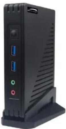
natural_image
Black electronic device rear panel with ports and ventilation slots (no visible text or symbols)Notes
- Please read this user manual carefully to ensure that you can use the device correctly and safely.
- There may be several technically incorrect places or printing errors in this manual. The updates will be added into the new version of this manual. The contents of this manual are subject to change without notice.
- This device should be operated only from the type of power source indicated on the marking label. The voltage of the power must be verified before using the same. Kindly remove the cables from the power source if the device is not to be used for a long period of time.
- Do not install this device near any heat sources such as radiators, heat registers, stoves or other devices that produce heat.
- Do not install this device near water. Clean only with a dry cloth.
- Do not block any ventilation openings and ensure proper ventilation around the machine.
- This machine is for indoor use only. Do not expose the machine in rain or moist environment. In case any solid or liquid get inside the machine's case, please turn off the device immediately and get it checked by a qualified technician.
- Do not try to repair the device by yourself without technical aid or approval.
Contents
1 Introduction....1
1.1 Welcome....1
1.2 Front & Rear Panel Instructions....1
2 Login....2
2.1 Login....2
2.2 Quick Wizard Settings....3
2.3 Main Menu Interface Introduction....4
3 Device Management 8
3.1 Add Encoding Device 8
3.1.1 Quickly Add 8
3.1.2 Manually Add....8
3.1.3 Auto Report....10
3.1.4 Quickly Add Auto Report Device 10
3.2 Modify or Delete Device....11
3.3 Device Area Selection....11
3.4 Batch Import/Export....11
3.5 Device Upgrade 12
3.6 Device Setting....12
3.7 Area Setting 12
3.8 Server Settings....13
3.9 Channel Group Settings....14
3.10 Task Management 14
4 Group Management....16
4.1 People Management 16
4.1.1 Add Group....16
4.1.2 Add Target....17
4.1 Vehicle Management....19
4.1.1 Add Vehicles....19
4.1.2 View, Modify or Delete Vehicles....20
4.1.3 Import or Export Vehicles....20
4.2 Permission Management....21
5 Search....25
5.1 Image Search by Face 25
5.2 Face Comparison Search....26
5.3 License Plate Comparison Search 26
5.4 Smart Snapshot Search....27
6 Face Greeting....30
7 Face Attendance....33
7.1 Add Devices and Targets....33
7.2 Attendance Configuration....33
7.2.1 Attendance Check Point Settings....33
7.2.2 Attendance Period Settings....34
7.2.3 Attendance Shift Settings 36
7.2.4 Personnel Scheduling 36
7.2.5 Attendance Handling....37
7.2.6 Holiday Settings....40
7.2.7 Basic Configuration 40
7.3 Search Attendance Record....40
7.4 Statistics of Attendance Data....42
7.5 Real-time Monitoring 42
7.5.1 Real-time Monitoring 42
7.5.2 Data Synchronization 43
8 Face Access Control....44
8.1 Add Face Recognition & Access Control Device....44
8.2 Permission Settings....44
8.3 Event Linkage....45
8.4 Record Search 45
8.5 Two-Way Talk....46
8.6 Real-Time Monitoring....46
8.7 E-Map Access Control 46
9 Video Preview....47
9.1 Video Preview....47
9.1.1 Monitoring Point View 48
9.1.2 Channel Group View 49
9.2 Smart View 51
9.2.1 Face Comparison....52
9.2.2 License Plate Comparison ....55
9.3 Plan View 58
9.4 PTZ Control....59
9.5 Instant Playback....60
10 Record & Playback 61
10.1 Record Configuration....61
10.1.1 Schedule Recording....61
10.1.2 Alarm Linkage Recording....62
10.2 Playback....63
10.2.1 Normal Playback 63
10.2.2 Smart Playback by Face 65
10.2.3 Smart Playback by License Plate 67
10.2.4 Playback by Time....67
10.2.5 Playback by Event....68
10.2.6 Playback by Tag 69
10.3 Record Backup 69
10.4 Search Picture....70
11 Alarm Management....71
11.1 Alarm Server Configuration 71
11.2 Alarm Configuration 71
11.3 SOP Settings....73
11.4 Alarm Task Settings....73
11.5 Email Setting....74
11.6 Alarm View 75
11.7 Alarm Log....76
11.8 Manual Alarm Out....77
12 E-Map 78
12.1 E-Map Settings....78
12.1.1 Create E-Map 78
12.1.2 Add Hotspot....78
12.2 E-Map Monitoring 79
13 TV Wall 80
13.1 Add Device....81
13.1.1 Add Decoder 81
13.1.2 Create and Connect Decoder 81
13.2 TV Wall Management....82
13.3 TV Wall System Settings....83
13.3.1 Channel Number Settings 83
13.3.2 Decoder Setting....83
13.3.3 TV Wall Alarm Linkage Settings....83
13.4 Video Preview....84
13.4.1 Decoder Input 89
13.4.2 Playback 89
13.5 TV Wall Task Setting....90
13.6 TV Wall Backup 92
14 Target Counting....93
14.1 Task Management 93
14.2 Real-time Statistics 93
14.3 Heat Map....94
14.4 Historical Statistics....95
14.5 Flow Control 95
15 Visitor Management 98
15.1 Add Access Control Devices....98
15.2 Apply for a Visit 98
15.3 Search and Export Visitor Record 101
15.4 Exception Handling....101
15.4.1 Extending Visit Time or Modify Access Point 101
15.4.2 Not Visiting/Leaving Beyond the Given Time....102
16 Parking Lot Management 104
16.1 Add Devices....104
16.2 System Settings....105
16.2.1 Parking Lot Settings....105
16.2.2 Vehicle Group Management 108
16.2.3 Block List Management....111
16.3 Vehicle Monitoring 111
16.3.1 Real-time Vehicle Preview....111
16.3.2 Pass Records....112
16.3.3 Pass Information 112
16.4 Integrated Search 112
16.4.1 Search Pass Information....112
16.4.2 Search Overdue Parking....113
16.4.3 Search Vehicles in the Parking Lot....113
16.5 Report Statistics....113
17 Body Temperature Measurement....115
17.1 Add Temperature Reading Devices....115
17.2 Temperature Screening....115
17.2.1 Configuration 115
17.2.2 Live Preview 116
17.2.3 Record Search 117
17.2.4 Statistics....117
18 Industrial Temperature Measurement....119
18.1 Thermal Network Camera Settings....119
18.1.1 Temperature Measurement Settings....119
18.1.2 Temperature Alarm Settings....119
18.1.3 Fire Detection Settings 120
18.1.4 Alarm Linkage Settings 121
18.2 Temperature Measurement....121
18.2.1 Video Preview 121
18.2.2 Data Analysis....122
18.2.3 Record Search 123
19 User Management 125
20 Operation and Maintenance Management....127
20.1 Check and Export Log 127
20.2 Backup and Restore Configuration 127
20.3 Viewing Online Status....127
20.4 Viewing Status Log....128
21 Configuration....129
21.1 Local Configuration....129
21.1.1 Basic Settings ....129
21.1.2 Resource Tree Settings 129
21.1.3 Record and Snapshot Settings....130
21.1.4 Alarm View Settings 130
21.1.5 Overload Settings....130
21.1.6 Snapshot Attribute Display Settings....131
21.1.7 Network Configuration....131
21.1.8 Server Port Configuration....132
21.1.9 System Time Configuration ....132
21.1.10 Upgrade System 133
21.1.11 Other Configuration....133
21.2 Server Configuration....133
21.2.1 System Settings....133
21.2.2 Alarm Settings....134
21.2.3 Parking Lot Settings....134
21.2.4 Audio Uploading Settings....134
22 Data Dashboard 135
22.1 Create Intelligent Dashboard....135
22.2 Basic Module 136
22.3 Face Comparison Display....137
22.4 Body Temperature Measurement Display....138
22.5 E-map Display 139
22.6 Smart Snapshot Display....141
22.7 Traffic Flow Statistics Display....141
22.8 Remaining Parking Space Display 142
23 Troubleshooting....143
1 Introduction
1.1 Welcome
Thank you for purchasing this product.
If technical assistance is needed, please contact Speco Technologies Technical Support.
Phone: 1-800-645-5516 option 3
Email: techsupport@specotech.com
1.2 Front & Rear Panel Instructions
The picture below is for reference only.


| No. | Description | No. | Description |
| 1 | USB3.0 *2 | 7 | Power button (LED) |
| 2 | Ethernet port (LAN) | 8 | USB3.0 *1 |
| 3 | USB2.0 *2 | 9 | USB3.0 *1 |
| 4 | HDMI output | 10 | Audio Input |
| 5 | VGA output | 11 | Audio Output |
2 Login
2.1 Login
Before starting, please make sure network cable, monitor and power are connected. After the server is started, the following window will appear as shown below.
Server mode or client mode can be selected when logging in. If "Client mode" is selected, you need to enter the address and port of the authentication/management server. Then this server will be used as a client. If "Server mode" is selected, this server can be used directly. Taking server mode as an example:
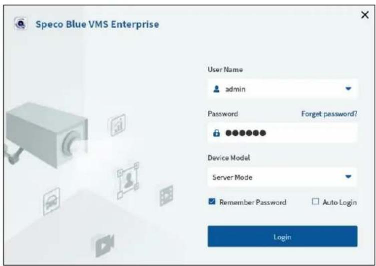
① Enter username and password (the default username is admin; the default password is 1234).
Check "Remember Password" or "Auto Login" as needed. If it is the first time for you to log in, you must check "I have read and agree Application Privacy Statement".
② Click [Login].
If you forget the password, please click "Forget password". Then a small window will appear. You can reset the password by answering the pre-defined questions.

If you don't set or forget the security questions and answers, you can reset your password by dynamic password. Click "Forget password" and then click "Dynamic Password" to go to the dynamic password page. Search the CPU ID, MAC address and the current time and then send the information to the technical staff to get the dynamic password.
2.2 Quick Wizard Settings
After you log in, a wizard will display and the password modification is required.

If this is the first time for you to log in, it is recommended to create security questions and answers.
It is important that you remember the answers for these questions or you will not be to reset your password and be locked out.
Click "Skip" to skip the following wizard setup.

Click "Next" to enter the network configuration interface. Set the network parameter according to the actual condition.
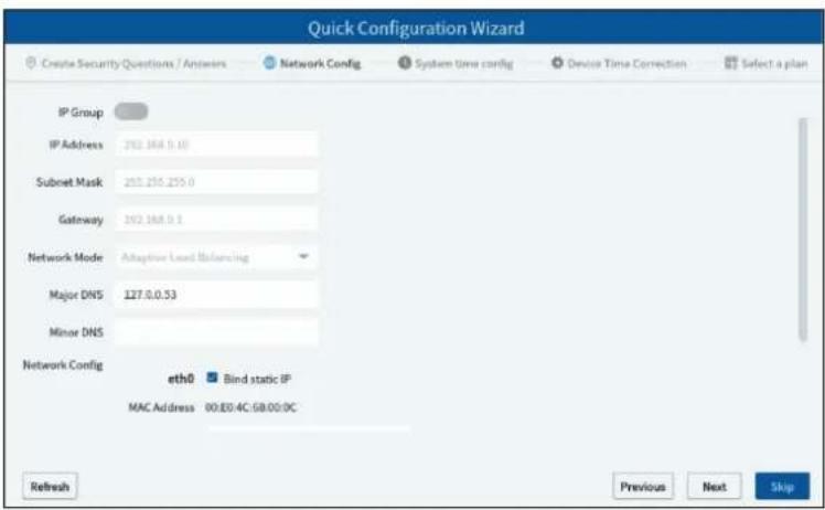
Click "Next" to set the system time as needed.
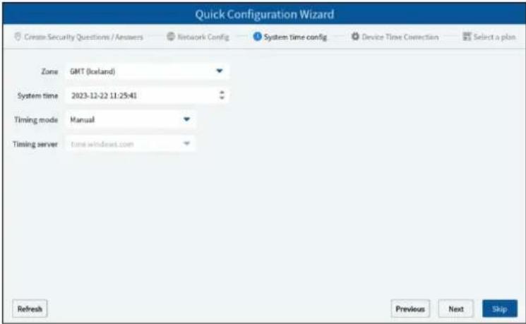
Click "Next" to set whether to synchronize the time zone of the added devices with the system.

Click "Next". Then you can select the function display module in the home page.
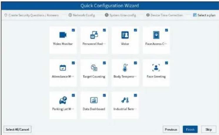
Click "Finish" to complete the wizard setup.
2.3 Main Menu Interface Introduction

There are five parts in the main menu interface. The descriptions of each part are as shown below.
Menu Bar
| No. | Description | No. | Description |
| 1 | Menu Bar | 4 | Status Bar |
| 2 | Tab Bar | 5 | Alarm Information Bar |
| 3 | Functional Areas |
Tab Bar
| Menu | Description |
 | “Video preview” |
 | Including “Switch User”, “Register”, “About”, “Switch Plan”, “Modify Password” and “Clear Cache Memory” |
 | Click to lock the operation page. Click “Unlock” and then enter the login password to unlock it. |
Functional area
| Menu | Description |
| Video preview | To view live images and to record, snapshot and talk, etc. |
| Record &Playback | To remotely play the local records or back up records. |
| Search | Including image search by face, face comparison retrieval, license plate comparison retrieval, smart snapshot retrieval and visitor record search. |
| E-Map | To manage and display maps, hot spots, etc. |
| TV Wall Management | To set TV wall and decoding videos on TV Walls |
| Group Management | To manage people and assign the access permission |
| Data Dashboard | Smart display video window, device status, face comparison, human body temperature screening, E-map, etc. |
| Parking Lot Management | To manage vehicles in the parking lot |
| Face Greeting | To welcome visitors based on face recognition technology |
| Face Attendance | To help to manage staff attendance based on face recognition technology |
| Face Access Control | To control people entry via access control panels |
| Visitor List | To manage visitors and search the records of visitors. |
| Target Counting | To monitor and analyze people/vehicle flow in real time |
| Body Temperature Measurement | To view the statistics of body temperature |
| Industrial Temperature Measurement | To view the real-time video, analyze data and search records. |
| Resource Management | To add, modify or delete areas, devices or servers. |
| User Management | To add, modify or delete user account and set permissions for these accounts. |
| Alarm Center | To set alarm linkage and schedule; To search alarm logs. |
| Operation and Maintenance Management | To search, export and maintain logs; To back up or restore configuration; To display device/server/record status |
| Configuration | To set record path, snapshot path, system startup and maintenance, overload, alarm view, etc. |
Favorites:
You can move the module which has a high using frequency to Favorites.
Place the cursor on the module you want to move to Favorites, and then a pentagram icon ( ) will be displayed on the top right corner
of the module. Click this icon to move. In the Favorites display area, click to make the module return to its original place.

Wizard Settings:
On the bottom right corner of the functional area, click 🔒 to show the following wizard guide.
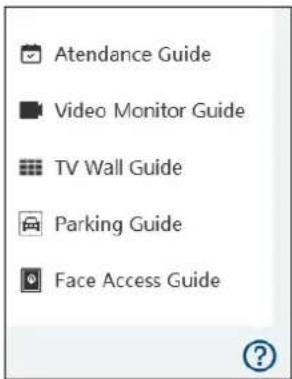
Other buttons:
| Button | Description |
| Click to shut down or reboot your device. | |
| Click it to add the video preview page. | |
| When the tab pages exceed the applicable numbers, this icon will display. Click it to view the hidden tabs. |
Common buttons:
| Button | Description |
| Click it to edit the item. | |
| Click it to delete the item. | |
| Check the camera and then click it to select | |
| Check the camera and then click it to remove | |
| Click it to add all cameras | |
| Click it to remove all selected cameras |
3 Device Management
3.1 Add Encoding Device
In the main menu interface, click "Add, Edit or Delete Device" to go to the following interface as shown below.

In the encoding device interface, you can view the activated device or inactivate device. Click the "Activate" tab to sort.
Activation: click "Not activated" and then enter the password of the IPC according to the tip in the pop-up activation box. After successful activation, the IPC can be connected normally.
Batch Activation: check the inactivate devices and then click [Activate] to enter the password of the IPCs in the pop-up activation box. After successful activation, these IPCs can be connected normally.
Then click "Add" to add devices. You can add multiply devices in this interface, such as face detection IPC, face recognition IPC/NVR, face recognition terminal, active deterrence IPC, LPR camera, etc.
3.1.1 Quickly Add
Click [Refresh] to quickly search devices in the same local network as shown below. Check the device and allocate the transfer server, storage server, area for it. After that, click [OK].
Click "Default password" to set the default username and password of the devices. The default username of the standard device is "admin and the default password of the standard device is "1234".
Note:
* The default media transfer server and storage server can be selected when adding devices.
* Area must be set up before adding devices. Click [Create Area] to create an area (See Area Setting).
3.1.2 Manually Add

① Enter IP address/IP range/domain name, username and password and choose protocol type.
② Click [Test] to test whether the device is connected successfully or not.
③ Select transfer server, storage server and area and then click [OK].
Devices can be added in batch by adding IP range.
If "URL" is selected, you shall add the device via RTSP protocol. Enter the URL, username and password of the device and then click [Test] to test whether the device is connected successfully or not.

How to get a URL?
Take one of our IPC as an example. Log in to the web client of the IPC and then go to "Config"→ "Network"→ "RTSP" interface to configure RTSP.
The default RTSP port is 554 and the URL format is "rtsp://IP or domain name:port/profile1". For example:
rtsp://192.168.1.1:554/profile1. Profile1stands for main stream; profile2 stands for sub stream; profile3 stands for the third stream.
For the URL of a device from other companies, please consult their technical documentation.
3.1.3 Auto Report
Select the "Auto Report" Tab to see the following interface.

① Enter the device ID set in the DVR/NVR or IP camera and choose the protocol.
- If the DVR/NVR is needed to add, please go to Network→Platform Access interface of the DVR/NVR. Check "Enable", enter the IP address and port (default 2009) of the SPECO BLUE VMS and then set the device number of the DVR/NVR.
- If the IP camera is needed to add, please go to Network Ports/Connections of the IP camera. Check the box next to "Enable", enter the IP address and port (default 2009) of the SPECO BLUE VMS and then set the device number of the IP camera.

② Select the transfer server, storage server, area and then click [OK].
3.1.4 Quickly Add Auto Report Device
For the auto report devices, you can go to the "Unbound Auto Report Device" interface to add them quickly.
Note: please fill out the auto report information in the NVR/IPC in advance and then the device information can be searched in the "Unbound Auto Report Device" interface.
3.2 Modify or Delete Device
After devices are added successfully, they will be listed as below.

The device channel number, alarm status, online status and record status can be viewed from the above table. Click to modify the device information; Click to delete the added device. Select the desired devices and click [Delete] to delete multiple devices simultaneously.
3.3 Device Area Selection
Select one or more encoding devices and then click [Change Area] to modify the area of the selected devices.

3.4 Batch Import/Export
You can import multiple encoding devices (NVR/IPC) in different local network at a time. The setting steps are as follows:
- Create an Excel file and then edit the device information as follows. Please copy the text of the first line.
| A | B | C | D | E |
| ip | port | protocol | userName | password |
| xxx.xxx.xxx.xxx | 6036/9008/80/554 | ipv4/sn/ipv6/domain/id/onvif/xxx | xxxxxx | |
Protocol: three protocols can be used here, including "ipc", "standard device" and "NVR".
- Save the file as ".cvs" or ".xlsx".
- Click Home→Resource Management→Add, Edit or Delete Device. Then click [Import/Export] to show a drop-down list. Click [Import] to import the file.
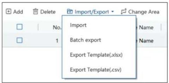
Export encoding devices: check the device you want to export and then click [Save Form] to export the device list.

3.5 Device Upgrade
In the "Add, Edit or Delete Device" interface, check the devices you want to upgrade and then click [Upgrade]. Select the upgrade type as needed.

Note: When multiple devices are upgraded simultaneously, the selected devices must be the same series.
3.6 Device Setting
Go to Home→Device Setting interface as shown below. In this interface, the parameters of the device can be set up.
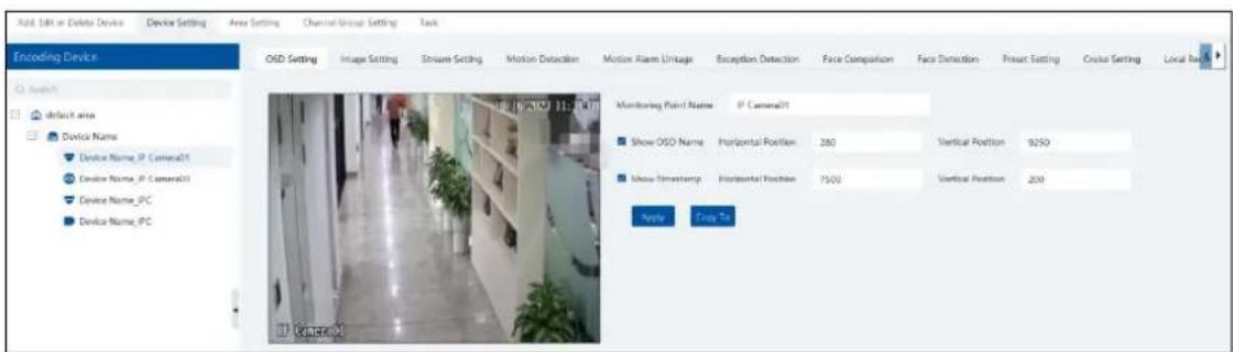
Different devices have different menus. Please configure the device according to the corresponding user manual.
3.7 Area Setting
Go to Home→ Area Setting interface as shown below.

Click [Add] to go to Area adding interface. Enter area name to create parent area. Then click [OK] to save the settings. To create sub area, click [Add], choose the parent area, enter the area name and click [OK].
3.8 Server Settings
- Add Storage Server
Storage server is in charge of the storage of record information, including the information of schedule record, record based on motion alarm, sensor alarm, smart detection alarm (like object removal detection, line crossing detection, etc.), responding to the search and playback of all storage data. It also supports self-defined storage path settings and IP-SAN access.
Note: If the device is logged in under server mode, you can only add one storage server. If the device is logged in under client mode, please add storage servers according to the performance of the connected management server.
If you want to add a storage server, please follow the directions as below.
- Click Home→Add, Edit or Delete Device→Storage Server.

- Click [Add] to go to storage server adding interface. Users can quickly add or manually add storage servers.
- Select the "Quickly Add" tab and click [Refresh] to quickly search servers in the same local network. Check the desired servers and click [OK] to save the settings.
Select the "Manually Add" tab to go to the storage server adding interface. Enter the server name, IP address and port and click [OK] to save the settings.
When adding the storage server, you can select it as a hot spare server. Once the host server is offline, the spare server will take over.
After the storage server is added, click 📄 to set record partition or disk.
If you have added a hot spare server, it will work as follows.
- When the storage server of the device is offline and the offline time exceeds the predefined service fault time, the recorded file of the device will be saved by the online hot spare server.
- When the original storage server of the device is online again and the online time exceeds the predefined server fault time, the recorded file of the device will be saved by the original storage server.
To set the server fault determination time, please go to Home→Configuration→System Configuration interface to set.

3.9 Channel Group Settings
Go to Home→Resource Management→Channel Group Setting interface as shown below.

① Click [Add].
② Enter channel group name, channel group and select the dwell time.
③ Select the parent channel group.
④ Add channels to the channel group. Check the desired channels and click > to add channels; choose the selected channel and click < to remove those channels; Click >> to add all channels; click << to remove all selected channels. You can also enter the key words to search the channels and then select them.
⑤ Click [Ok] to save the settings.
3.10 Task Management
Set the face capture source, schedule and applicable scenario.

Face Capture by IPC: it is applicable to the face detection camera.
Face Match by IPC: it is applicable to the face recognition camera.
Note: Face recognition NVR, Temperature Reading Panel, Thermal network camera and IPC without face detection function cannot set task
here.
More parameters about face comparison can be set by clicking [More Settings].
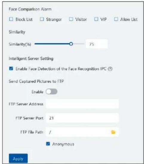
Face Comparison Alarm: Select face comparison alarm list. For example, "Allow List" is selected, when a person is detected and is successfully compared with the allow list, alarms will be triggered.
Similarity: Set the similarity of the face comparison.
Intelligent Server Setting: please check "Enable face detection of the face recognition IPC" as needed.
If checked, the intelligent server will get all face capture pictures of the IPC after you configure face comparison parameters and set the schedule for the IPC. All these face snapshots can be searched in the Search interface (Home→Search).
If unchecked, the intelligent server will only get the matched face snapshots after you configure face comparison parameters and set the schedule for the IPC. Only the face snapshots successfully matched with the face database can be searched in the Search interface (Home→Search).
FTP Settings: Send the captured pictures to FTP. Please set the corresponding parameters according to your FTP server.
4 Group Management
4.1 People Management
You can add group for three libraries—Person List, VIP List and Block List.
Here taking "Add target to person list" for example
4.1.1 Add Group
- Add the parent group
Go to Home→Group Management→People Management→Person List.

Click [Create] to add a group, or right click on the blank of the person list column and then the "Add" button will appear. Click it to add the group name.
Note: The added parent group name and face information under it will be synchronized to the face database of the NVR, but the sub group name will not be added to the NVR. The face information under the sub group will automatically be added to its parent group in the NVR. If the parent group fails to synchronize to the face database of the NVR, but the face information of sub group is successfully added to the NVR. Now, the face group name will be named "creation date-intelligent server IP-creation time (s)-list type-parent group name" as shown below.
| No. | Group |
| 1 | 2022_4_21_10.214.200.200_32 (3853) |
| 2 | 2022_4_22_10.214.200.111_1 (1128) |
| 3 | 2022_4_22_192.168.52.214_47_White_default(0) |
Group Name in NVR
For IPC, the added face information under person list and VIP list will be automatically added to the allow/white list of the IPC. The added face information under visitor list and block list will be synchronized to the corresponding list.
- Add the sub group:
Put the cursor on the parent group name and then you will see the follow buttons. Click "+" to add the sub group name.

4.1.2 Add Target
You can add targets for three libraries—Person List, VIP List, Block List.
- Add target one by one
Select the group name and then click [Add] to add the target information

Click [Upload] and select the face image saved in the local PC. Then fill out the corresponding information and click [OK] to save.
Note: the resolution of the face image shall be less than 200KB.
If the target is added to the group of the VIP, register date and VIP level shall be fill in.
If the target you newly add has already existed in the authorized face recognition device, please delete the previous one in the authorized face recognition device in case that the successful match result cannot be pushed to the platform.
- Batch Import
In the above interface, click [Download template] to export an Excel template and then fill out the corresponding information in the table as shown below.
After that, create a file named "Image" and then put the face images under this file.

Put the image file and the personal information file into the same directory.
Click [Import]→[Excel Import]

Click [Import] and then select "Batch import" to import face pictures in bulk, but the target information must be modified manually. Click [Import] and then select "File import". You can select whether to search the sub folder.
Search Subfolders: choose a folder including multiple subfolders and then all pictures in the folder and its subfolders will be imported. Not Search Subfolders: the pictures in the folder will be imported, but the pictures in the subfolders will not be imported.
➢ Convert images to an Excel
Multiple images also can be converted to an Excel. Then click "Excel Import" to add targets. The setting steps are as follows.
- Name the face images (like David_Male_1989-01-03_Engineer_Group1), separating each field with “_”.
- Click on "Formatting Tools" to display image conversion Tool box. Click to select the desired images.
- Click respectively to set the image naming rules and content of the header.
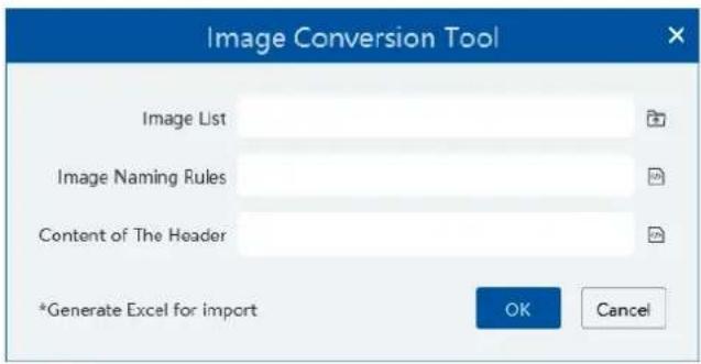
Note:
- The naming sequence of each image selected must be the same. Please select the image naming rules in accordance with the sequential order of the name of the image.
- The content of the header must contain those items of the image name and can be selected in any order.
- The content of the header must contain name and group (face database), which can be entered in the image name in advance and also can be edited in the exported Excel.
- Modify or Delete Target

After the target is added, click to modify; click to delete.
Click to view the target list as shown below.

Click "Custom" to customize the target display information.
Click "Change group" to change the group.
4.1 Vehicle Management
4.1.1 Add Vehicles
- Add vehicle groups for each vehicle list
Click ☐ on the right of a vehicle list (Allow List/Block List/Temporary Vehicle) to add a vehicle group under the vehicle list as shown below.
Note: If you want to add vehicle groups under a vehicle list, you must enable license plate synchronization function by clicking Configuration→Server Configuration→System Setting first.

Select the desired vehicle list or vehicle group under a vehicle list and then click [Add] to add the relevant vehicle information.

▶ Binding devices for each vehicle group
Click beside the group name to bind devices for this group. All vehicles under this group can be bound to the selected devices. After
these devices are bound to this group, the vehicles you add later will automatically bind these devices.

4.1.2 View, Modify or Delete Vehicles
After you add the vehicle, you can view, modify or delete the vehicle information as needed.

Select multiple vehicles and then click the [Delete] button to delete multiple vehicle information at once.
4.1.3 Import or Export Vehicles
Click [Export Template]→Export Template(.xlsx/.csv) to export a template. Then fill out the relevant vehicle information.

After that, click [File import] to import the vehicle information. Click [Export] to export the added vehicle information.
You can also get vehicle information from license plate recognition cameras/NVRs. The setting steps are as follows.
- Click "Obtain from Devices".
- Select the device type.
- Select vehicle list (Allow List/Block List/Temporary List) of the LPR camera/NVR.
-
Select a vehicle group of the platform.
-
Click

- Click "OK" to synchronize the vehicle list of the selected device to the corresponding groups of the platform.

Note: If you want to get license plate information from devices, you must enable license plate synchronization function by clicking Configuration→Server Configuration→System Setting first.
4.2 Permission Management
Click Home→People & Vehicle Management→Permission Management to go to the following interface.
You can view the sync records or bind the camera to the group or people.
➢ Add Permission Group
In the permission group interface, click [Add] to add a permission group. Enter the name and set the schedule and devices as needed.
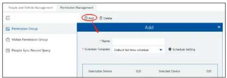
Click "Schedule Setting" to set the desired schedule. You can set weekly schedule and holiday schedule as needed.
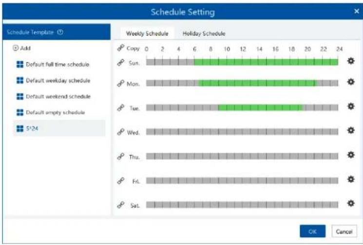
Click [Add] to add a new schedule template name. Double click the schedule name to modify it. Then you can select the schedule and set it as needed.
● Weekly Schedule:
Set the scheduled time from Monday to Sunday for a single week. Each day is divided in one hour increments. Green means scheduled. Blank means unscheduled.
Add: Add the schedule for a special day. Drag the mouse to set the time on the timeline. Or click

to manually set the time period;
click + to add new time period.

You can copy the above time period to other days by checking the relevant days. After that, click [OK] to save the settings.
Additionally, you can also copy the time period by clicking ☐. For example, click ☐ in front of Sunday, Monday and Tuesday, and then drag the mouse on the timeline of one of them. After that, other days that enable ☐ will automatically copy the set time period. You can also click ☐ next to "Copy" and then drag the mouse on the timeline of one day, and then the other days of the week will automatically copy the set time period.
Erase: Drag the mouse on the scheduled time period to delete the set time.
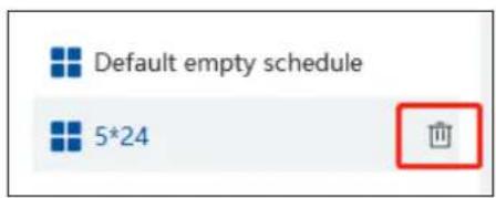
Delete Schedule: Put the cursor on the schedule name and then a deletion icon will appear. Click it to delete the schedule.
- Holiday Schedule
Set the scheduled time for a special day, such as a holiday.
- Click the "Holiday Schedule" tab to enter the holiday schedule page.

- Click "Holiday Schedule Setting" to set holiday schedule. Click "Add" on the left panel to add a new holiday schedule. Enter the holiday schedule name as needed.
- Select the holiday schedule. Click "Add" on the right panel to set date and time period.
- Drag the mouse on the timeline to set the time period or click to manually set the time period. Click "Clear" to clear all information of the current holiday schedule.
- Click [OK] to save the settings.

Note: Holiday schedule takes priority over weekly schedule.
▶ Permission Binding
Click to bind the group or person to the selected devices.

After the binding is complete, you can modify or delete the permission group as needed.
People Sync Record Query
Click "People Sync Record Query" to view the permission binding status of each person.

After the permission binding is complete, you can click to delete the sync record here.
Note: 1. When the device is offline, the target synchronized to it cannot be deleted. Then you can delete the synchronization records here and then delete the target.
- The added group or person must be bound with one or more cameras, or the face comparison result will not be gotten by the platform.
➢ Vehicle Sync Record Query
Click "Vehicle Group" or "Device" to view the sync status of all vehicles under each vehicle group or device.

Note: If you want to view the vehicle sync records, you must enable license plate synchronization function by clicking Configuration→Server Configuration→System Setting first.
5 Search
5.1 Image Search by Face
- Select a picture and picture source.
- Set the start time and the end time.
- Set the maximum count and similarity.
- Click [Search].
Note: Only face recognition NVRs added to this platform support this function.

Click to play the record in a small window.

E-Map Track View:
Create an E-map. You can create or delete an E-map in this interface. The hot spot can be added to the E-map too.
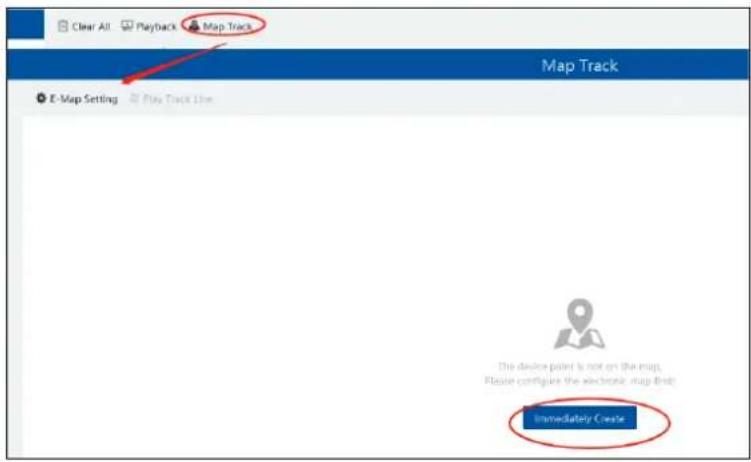
Play Track Line: Click this button to play the track line on a map.
Playback by Tracks: Click this button to play the track video.
5.2 Face Comparison Search
- Go to Search → Face comparison retrieval interface.
- Select the IPC and query method. Then select match type or target as needed.
- Set the start and end time and then click [Search] to search the face pictures.

5.3 License Plate Comparison Search
- Select the camera.
- Enter the license plate and select the match type.
- Set the start time and end time.
- Click [Search]

5.4 Smart Snapshot Search
The snapshot results from the intelligent server and face recognition devices can be searched. You can search the snapshots of human face, human body, motor vehicle and non-motor vehicle.
For example: Search faces from intelligent server

If the snapshot type is human face, put the cursor on the captured picture and then some shortcut buttons will be displayed.

Click +to add the capture picture to the library. Select the library on the left and then fill out the information of this target. Click [OK] to add.
Put the cursor on the captured picture and then click to quickly search images by this picture. Put the cursor on the captured picture and then click to quickly download the captured picture.
Search vehicles from intelligent server:

Click to quickly skip to the playback interface and play the record.
Click ☐ to view the snapshot details, including the original image, target picture, snapshot type, snapshot time and so on.
Select the searched pictures as shown below and click [Export] to export the selected pictures.

You can also export all searched pictures in the current page once by checking "Select Current Page" and clicking [Export].
Search vehicles from face recognition NVR:
Click to play back the record in a small window; click to quickly download the captured picture.
6 Face Greeting
Face Greeting: After successful face comparison, the words/voice of welcome will be heard by the guests and their photos will be shown on the screen.
Click "Face Greeting" to go to the face greeting interface. The setting steps are as follows:
① Create a VIP group and add targets for this group in the VIP list interface. Then set a permission group for them. The setting details are similar to adding targets to the person list. See chapter 6 for details.
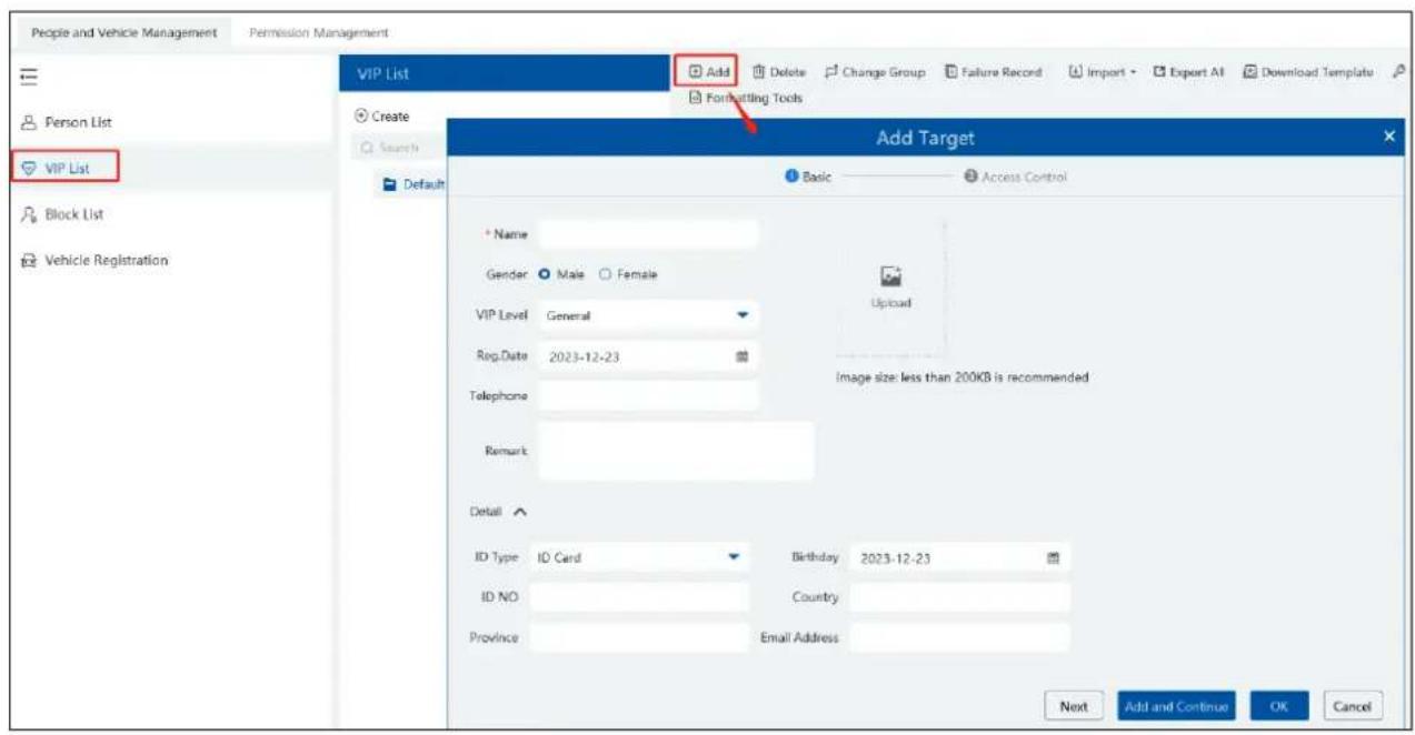
Note: The camera for face greeting must support face recognition function, such as face recognition and access control panel, face recognition camera and so on.
If the person added to the person list adds to the VIP list again, this person may be not recognized as a VIP person. Please delete this person in the person list first.
② Select the schedule, face match type in the Task interface (See Task Management for details).

③ Real-Time Monitoring. Drag the camera name to the preview window. When there are targets detected, the match result will be displayed on the right panel.
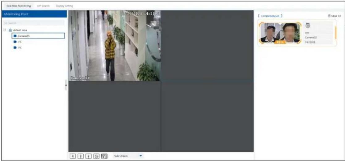
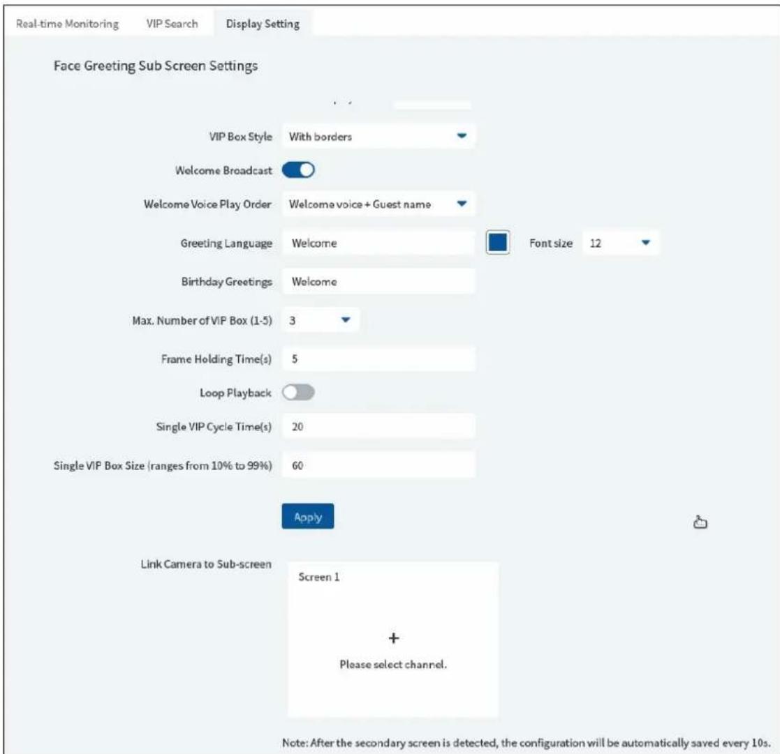
④ View the match result of the greeting screen. Click the "Display Setting" tab to set the sub screen (greeting screen).
In this interface, greeting screen background style, screen display mode, VIP box style, face greeting language and so on can be set up. Select the sub-screen display channel: if the secondary monitor is connected to the device, "+" will display in the Link Camera to Sub-screen box. Click "+" and choose the desired cameras you want to display in the sub-screen and then click [OK] to save the settings. Multiple cameras can be selected at a time.
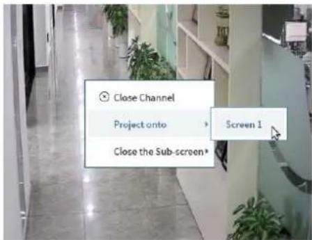
Sub-screen display: in the real-time monitoring interface of Face Greeting, right click on the desired channel and select the sub-screen you want to display by clicking "Project onto".
Greeting Screen Background Style: three options: Video, Background Picture and Pure Color Background
Screen Display Mode: 1/4/9/16 screen display mode can be selected.
VIP Box Style: with borders or pure image.
Welcome Broadcast or Not: if enabled, the welcome voice will be broadcasted when the VIP person is successfully recognized.
Welcome Voice Play Order: choose which one to broadcast first between welcome voice and guest name
Greeting Language: please enter the content and select the color as needed.
Max. Number of VIP Box: up to 5 boxes.
Frame Holding time: set the duration time of VIP box appearing after the captured face is matched successfully.
Loop Playback: if enabled, the VIP name will be broadcasted in a loop.
Single VIP Cycle Time: set the time of the single VIP name broadcasted.
Single VIP Box Size: set the percentage of VIP box size occupying the entire screen.
⑤ Search the face greeting records. Click "VIP Search" tab as shown below.
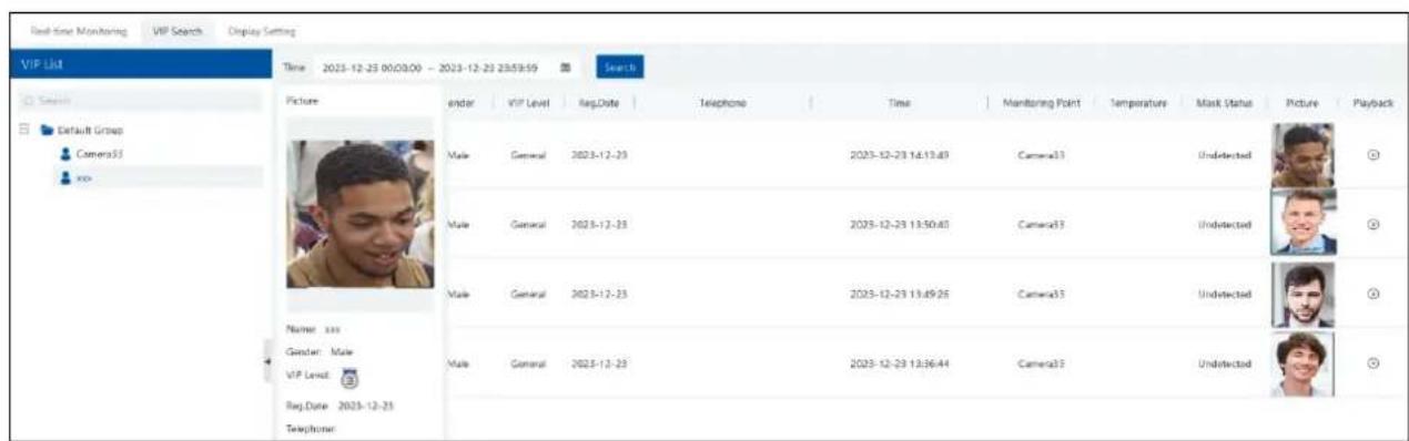
You can enter the key word to search the target or manually select the target from the library. Then set the start time and the end time and click "Search" to search the record. The detailed information of this target will be shown. Click 📋 to play the record.
7 Face Attendance
Click ⚙ at the bottom right corner to select "Attendance Guide" to quickly set the attendance.
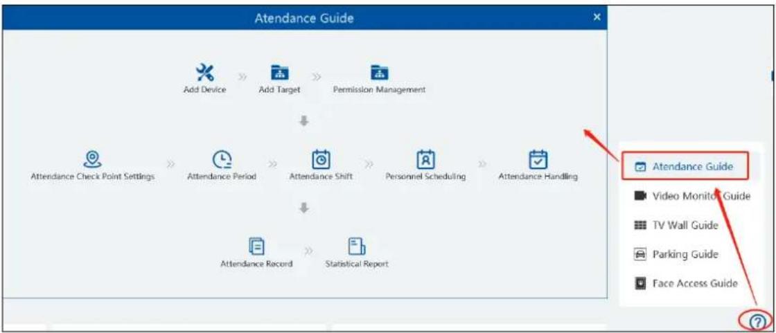
flowchart
graph TD
    A["Add Device"] --> B["Add Target"]
    B --> C["Permission Management"]
    D["Attendance Check Point Settings"] --> E["Attendance Period"]
    E --> F["Attendance Shift"]
    F --> G["Personnel Scheduling"]
    G --> H["Attendance Handling"]
    I["Attendance Record"] --> J["Statistical Report"]
    K["Attendance Guide"] --> L["Video Monitor Guide"]
    K --> M["TV Wall Guide"]
    K --> N["Parking Guide"]
    K --> O["Face Access Guide"]
In the attendance guide interface, click the corresponding menus in sequence to quickly set the attendance.
7.1 Add Devices and Targets
Add Devices
In the attendance guide interface, click "Add Device" to enter the encoding device interface. Click [Add] to add the face attendance device (eg. face recognition panel).
Add Targets
After the attendance device is added successfully, click at the bottom right corner to expand the attendance guide. Click "Add Target" to go to the person list interface.

In the person list interface, add the attendance group and targets as needed. Refer to People Management for details.
Note: The compared person in attendance system shall be added in the person list in advance. One person only can be added in one group. If this person also be added in other groups (like VIP list), the attendance comparison result will not be obtained.
▶ Permission Management
Set the permission for the attendance group or targets. Refer to Permission Management for details.
7.2 Attendance Configuration
7.2.1 Attendance Check Point Settings
Select the attendance device and then click [Set Check Points]. Enter the name and remarks in the pop-up window. Then click [OK] to save the settings.

7.2.2 Attendance Period Settings
If a company has different working time for different employees, you can add different attendance rules.
Click [Add] to set the detailed attendance rule.
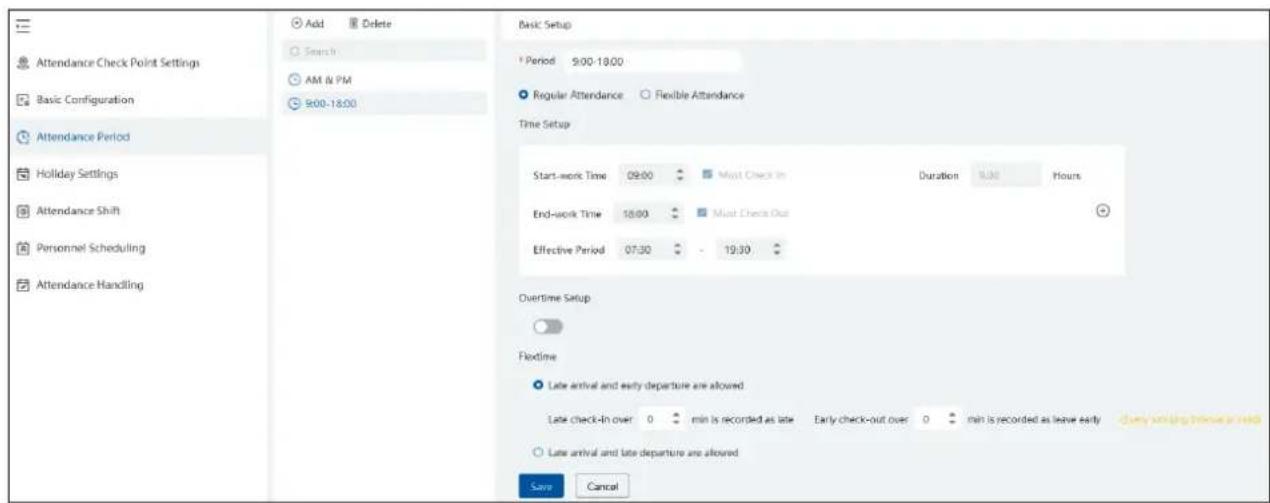
▶ Regular Attendance
Set the attendance period name and working time. Then click [Save] to save the settings. Click [Add] again to add next attendance period.
Basic Setup: set the normal working period.
Time Setup:
Start-work time: the normal start-work time
End-work time: the normal end-work time
Must check-in/out: "Must check in" next to the first check-in period and "Must check out" next to the last check-out period are checked by default. That is to say, in the first check-in period, the employees must check in; in the last check-out period, the employees must check out. During the period that "Must check in/out" is not checked, the employees don't check in/out, who will not be regarded as "Not check in/out" or "Absent".
Effective check-in/out time: Set the effective check-in/out period. If the employees check in/out before/after this period, the check-in/out will be invalid and will be regarded as "Not check-in/out".
Work hours: automatically calculate according to the start-work and end-work time.

Overtime setup: there are three overtime levels. Please set as needed.
Note: The end-work time of overtime setup must be within the effective period of basic setup.
You can deduct the dinner time when counting the overtime. You can also enable "Check in for overtime working" as needed.
Deduct dinner time: if checked, the system will automatically deduct the dinner time from the overtime. The overtime level depends on the time duration after deducting the dinner time.
Flextime:
You can enable/disable "Late arrival and early departure are allowed" or "Late arrival and late departure are allowed".
Late check in over xx min is recorded as late: set the allowable minutes for late. If the employees check in within the period after the start-work time, the status will be "Normal".
Early check-out xx min is recorded as leave early: set the allowable minutes for leave early. If the employees check out within the period before the end-work time, the status will be "Normal".
For example: The start-work time is set as 09:00, and the late allowable duration is 20 minutes. If the employee checks in at 9:15, the attendance status will be "Normal".
Late arrival and late departure: for example, the limit time is set to 30 minutes and the normal working time is 9:00\~18:00. If the employee checked in at 9:30, he/she should check out at 18:30
▶ Flexible Attendance
Statistical methods: "Calculate records in pairs" or "calculate the first and last record"
Calculate records in pairs: Add up the time period between each two check records. The time interval of each two records must be more than 1 minute.
Calculate the first and last record: Calculate the time period between the first and last check records.
Work Hours: Set it as needed.
For the set attendance period, put the cursor on the attendance period name and then icon will appear. Click it to modify the attendance period. Select the attendance period and click [Delete] to delete the attendance period.

7.2.3 Attendance Shift Settings
Attendance Shift: The employees shall perform their duties according to the shift schedule.
Click [Add] to set the shift name and shift schedule.
Shift cycle can be set by day, week or month. The schedule will automatically repeat according to the set day(s), week(s), month(s) or years.
Day: You can customize the attendance period of each day. The number of days should be between 1 and 31.
Week: The schedule will repeat every 7/14/21/28/35 days based on the week.
Month: You can customize the attendance period of each month.
Year: You can customize the attendance period of each year
Working overtime on days off:
You can set overtime on weekends or holidays.
Work hours: set it as needed. For example: work time is set to 8 hours, the overtime will be calculated as 8 hours even if the actual working time is more than 8 hours. If the actual working time is less than 8 hours, the overtime will be calculated according to the actual working time.
7.2.4 Personnel Scheduling
You can set different schedule for different attendance groups or employees.
Select the attendance group or employee and then click [Scheduling] to select the shift and schedule start time and end time. Finally, click [Ok] to save the settings.

If the schedule for the attendance group or the employee needs to modify, select the group or person, click [Delete the scheduling] to delete the current schedule.
If there is something wrong with the attendance shift, you can select the person or group on the left and click [Scheduling] to modify.
When the temporary scheduling is needed, select the person or group, click [Temporary Scheduling], select date and period. After that, click [OK] to save the settings.
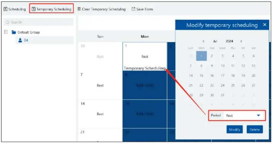
If you want to modify the temporary scheduling, you can select the person or group and click [Temporary Scheduling] to modify. Click [Delete] to delete the temporary scheduling of the day.

Select the group /person and click [Clear Temporary Scheduling] to clear all temporary scheduling of this group/person.
If you want to delete the scheduling, click ≡ at the top right corner. Select the group or person and then click [Delete the Scheduling] to delete the scheduling.

7.2.5 Attendance Handling
If someone needs to apply for leave or correct the check-in/out record, you can enter the attendance handling interface to set up.
Leave/Business-Trip Settings:
① Select the employee who wants to apply for leave or do business trip.
② Click [Leave/Business-trip].
③ Select the date the employee wants to apply for leave or do business trip.
④ Select the type, sub type, leave time and remark.
⑤ Click [OK] to save the settings.

: click it to set the sub type of leave or business trip.

Cancel Leave/Business-Trip:
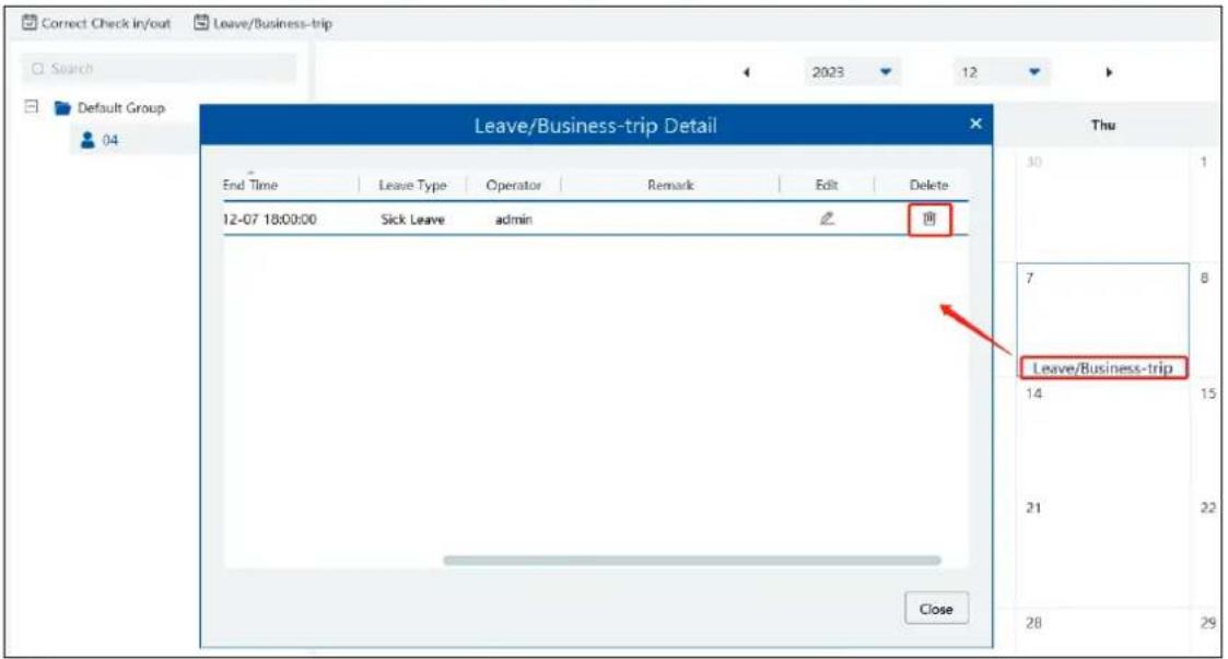
When the leave or business-trip cancels, you can go to the attendance handling interface to cancel it.
- Select the person you want to cancel the leave/business-trip and then a timetable will display.
- Clicking on the Leave/business trip tag will display a Leave/business-trip detail box.
- Move the slide bar to the right as shown below. Click to cancel this item.
Correct Check-in/out Time:
You can correct check-in/out time for the exceptional records according to actual needs. If the employee actually starts and ends his/her work in the normal working time but he or she forgets to check in/out, then "Correct Check in/out" function can be used.
- Select the person you want to correct the check in/out record.
- Find the desired date and then click [Correct Check in/out].
- Correct the check-in/out time as needed.
- Click "OK" to save the settings.

On the day that you correct check-in/out time, an icon (

) will appear. Click this icon to view the details.

7.2.6 Holiday Settings
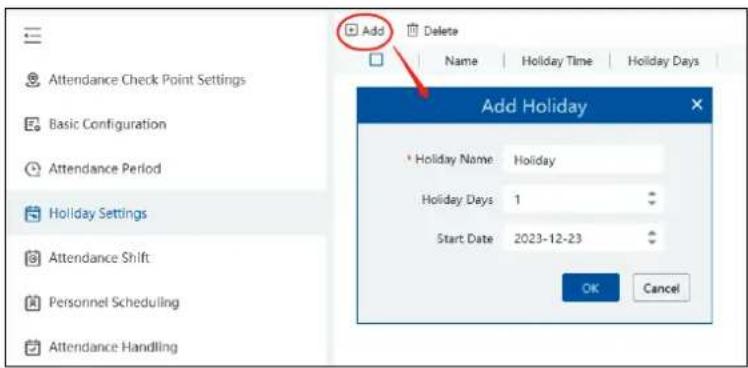
You can set a special day as a holiday. The holiday here takes priority over the attendance shift. That is to say, once a day is set as a holiday, there is no need for you to check in even if it is scheduled in the working day.
In the holiday settings interface, click [Add] to add the holiday as needed.
7.2.7 Basic Configuration
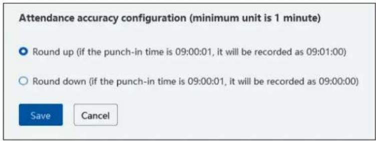
In this interface, you can set the attendance accuracy.
7.3 Search Attendance Record
You can search the desired attendance records to view the employee's attendance status by filtering the conditions, such as attendance group, name, etc.
Statistics by day/month
Click "Statistics by day", select the employee, set the time and click [Search] to view the attendance status of the employee on each day (including late, early leave, absent, overtime, etc.)

Click [export] to export an Excel of the attendance result. These exporting items can be customized as needed.
Click "Statistics by month", select the employee, set the time and click [Search] to view the attendance status of the employee in each month (including late, early leave, absent, overtime, etc.)
➢ Attendance Record
In this interface, you can search the attendance by temperature and mask-wearing status.
Export Reports
In the statistical reports interface, you can generate Excel daily/monthly/abnormal attendance report and export them to the USB flash drive.
▶ Send Reports Regularly
You can regularly send the statistical report to the designated email address. The setting steps are as follows.
Click "Send reports regularly" and go to its setting interface. Click [Add] to fill out the report type, employee, delivery date, send time, mail title, text and recipient.
Note: At the sending time point, the authentication server (management server) must be online and connected by a monitor client. Report type: daily report, monthly report and abnormal attendance report.
Delivery Date: Daily report: next day; Monthly report/abnormal attendance report: the first day or the last day of each month Recipient: The email address of recipient must be added in the person list (Group management→Person List) as shown below. In addition, the email address of the sender has been set in the email settings interface. Please see Email Settings for details.

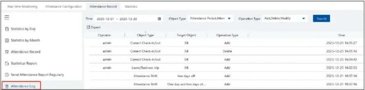
➢ Search Attendance Log
7.4 Statistics of Attendance Data
In the statistics interface of Face Attendance, you can view the attendance data in the form of chart.
Granularity: Group or human can be selected. If Group is selected, the attendance data of each group (department) can be viewed.
If Human is selected, the attendance data of the employees in the group (department) can be viewed.
You can quickly view the attendance data by week/month/year and also can view the attendance data in a specified period.
![Full-time Monitoring Attendance Configuration Attendance Record Statistics [ Statistics ] Group All Grav Transparency Group Week Month.Year 2023-12-23 - 2023-12-23 Search [ Export Picture Late 0 Leave Early 0 Absent 0 Overtime 0 Leave 0 All Departments](/content/2026/05/994503/images/6b797f6f83843582fe1931518f4ab3862ffb50b3516dae806961769228cf0dfd.jpg)
7.5 Real-time Monitoring
7.5.1 Real-time Monitoring
Go to Face Attendance→Real-Time Monitoring interface. Face comparison information can be viewed after the camera is dragged to the preview window.
Note: The compared person in attendance system shall be added in the person list in advance. One person only can be added in one group. If this person also be added in other groups (like VIP list), the comparison result will not be obtained.
![Real-time Monitoring Attendance Configuration Attendance Record Statistics Monitoring Point C:\Users\ defect area IPC [ Attendance Overview ] Lib Name All Auto Refresh Interval 30 mins Actuality/Should Active My Data 0/0 The arrival status of subordinate departments No Data Comparison List Clear All • Allow List IPC 12-23 15:15:04 页 02%](/content/2026/05/994503/images/195487ba7f2faaad0f46cf6452a2c81ba1d3faa9b4be1428e7dd1c1bf7e0e945.jpg)
Attendance overview: you can view the number of people who should arrive or actually arrive.
7.5.2 Data Synchronization
When the attendance device/transfer server/intelligent server is offline within a short time, there are attendance data generated during
this time. After the above-mentioned device or server is online, click at the top right corner of the camera deployment interface and then the synchronizing task will be triggered. Up to 6-hour offline time are supported for the attendance device. So, the system will synchronize the attendance data within 6-hour time to the platform after the device is online
Note: The attendance device must support synchronization function, or this function cannot be used.
8 Face Access Control
Click at the bottom right corner to select face access control guide.

In the face access control guide interface, click the corresponding menus in sequence to quickly set the face access guide.
8.1 Add Face Recognition & Access Control Device
Go to Resource Management→Add, Edit or Delete Device→Encoding Device interface. Then click [Add] to add the face recognition & Access Control device.
After the face recognition & access control device is added, please enter the device setting interface to configure tamper alarm, door contact configuration, door lock and wiegand configuration (varies by models).

8.2 Permission Settings
Go to the permission management interface. Add a new permission group or add the face recognition& access control device to the added permission group.

8.3 Event Linkage
In the event linkage interface, you can set alarm linkage items for anti-tampering alarm or door contact alarm

8.4 Record Search
1. Pass Record
In the record search interface, you can search the pass records by time, type and device.
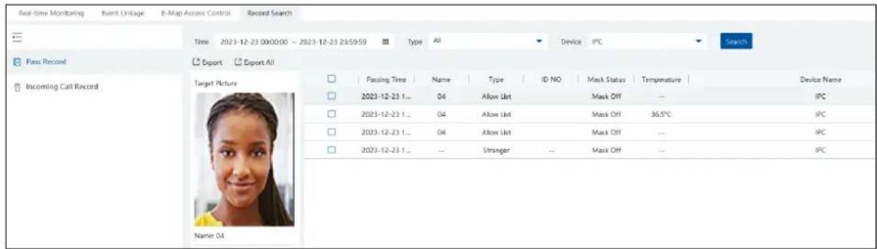
Select the "Stranger" type. Click [Add to library] to add the stranger to the face database.
Click [Export] or [Export All] to export the Excel pass records.
(2) Incoming Call record
In the incoming call record interface, you can search the call record between the monitor client and the device.
8.5 Two-Way Talk
Before using this function, please make sure that the face recognition and access control device is added successfully.
When someone presses the call button in the device, the client will receive the two-way talk request. Click

to answer; click

to hang up. During the two-way talk period, you can control the door contact through the buttons at the bottom of the two-way talk window. These buttons include "Open door", "NO", "NC" and "Recovery to Normal".
Note: Only one client can answer the call at a time. When another client answer the call, the two-way talk of this client will be hung up.
8.6 Real-Time Monitoring
Go to the real-time monitoring interface and then click "View". Choose the face recognition &access control panel as shown below.
![Real-time Monitoring Event Linkage E-Map Access Control Beyond Search Monitoring Point IPC 2023/12/23 05:24:39 [ Pass Record ] Search default area IPC Verified Target Info(details) Comparison Results Details Name: 04 Gender: Female Birthday: 2023-12-23 Lib Name: Default Group ID Type: ID Card ID No. Work ID Refresh Alert Source: IPC Alert Time: 2023-12-23 16:34:13 Allow List IPC 12-23 16:34:13 OK Cancel](/content/2026/05/994503/images/7ba794c4854e49933aa0ad0d18bfbb3d835df521495f4201c192ae8d58f62076.jpg)
Click "List" to display the linked access control equipment. Double click the door icon to show the live video. You can do the following operations, including "Open Door", "NO", "NC", "Recovery to Normal", "All Normally Open", "All Normally Closed", "All Recovery to Normal" as shown below.
8.7 E-Map Access Control
Go to the E-Map Access Control interface. You can filter the access control alarm type as needed, including "Monitoring point-tamper alarm" and "Monitoring point-door contact alarm".

9 Video Preview
9.1 Video Preview
Go to Home→Video Preview interface as shown below.

The descriptions of the video preview buttons are as follows.

| Button | Description | Button | Description |
| 1 | Screen display mode; click 📋view more screen display modes. Please select as needed. | 6 | Show/hide target tracking box |
| 2 | Full screen | 7 | Close all previews |
| 3 | Enable/disable OSD | 8 | Save the current view mode |
| 4 | Enable/disable broadcast | 9 | Export snapshots |
| 5 | Manual alarm output |
4:3/16:9/Original Aspect Ratio/Full-Win: window display ratio, please select it as needed.
Toolbar on the display window:
| Button | Description | Button | Description | |
 | Close image |  | 3D zoom in | |
| [A4H4X] | Start/stop recording | [3SHT] | Zoom in | |
 | Snapshot | [WC03] | Zoom out | |
 | Enable/disable audio |  | Fit to window | |
 | Enable/disable talkback | [K740] | Manual alarm output | |
| [E237W] | Enable/disable channel talkback |  | Monitoring point setting (camera setting) | |
 | PTZ control | |||
When the IPC under the DVR/NVR device has access to the channel, click 📄 to enable two-way audio between the DVR/NVR and the
monitor client; click 📄 enable two-way audio between the IPC and the monitor client.
Right-click button function:
| Menu | Description | Menu | Description |
| Close Channel | Close image | Start Channel Talkback | Enable/disable two-way audio between the channel and the monitor client |
| Start Record | Start/stop recording | Channel Info. | Display channel name, IP address and the current stream |
| Instant Playback | Click it to play back immediately | Stream | Choose video stream |
| Audio ON | Enable/disable audio | Full Screen | Display image in full screen |
| PTZ Control | Click it to show PTZ control panel | Image Adjustment | Set the image's brightness, saturation, contrast and so on |
| Snapshot | Capture images | Manual Alarm Out | Click it to select alarm output device and then trigger alarm out manually |
| Start Talkback | Enable/disable two-way audio between the device (eg. NVR) and the monitor client |
4:3/16:9/Original Size/Full Screen: screen display proportion; please select it as needed.
Note: the platform only can enable audio of one window. If the audio is enabled in one window, the audio in previous window will be disabled.
9.1.1 Monitoring Point View
- Start View
To start video preview, please drag cameras from the list to the right display window or select a window and then double click the camera. The image can be dragged to any window at random.

- Stop View
① Place the cursor on the video preview window to display the menu toolbar and then click 📄 to stop viewing.
② Right click on the video preview window and then select "Close Channel" to stop viewing.
③ Click ☒ on the toolbar of the video preview interface to stop all videos.
9.1.2 Channel Group View
Channel Group Setting
① Go to Home→ Channel Group Setting interface as shown below.

② Click [Add].
③ Enter channel group name, channel group and dwell time.
④ Select the parent channel group.
⑤ Add channels to the channel group. Check the desired channels and click > to add channels; choose the selected channel and click < to remove those channels; Click >> to add all channels; click << to remove all selected channels. You can also enter the key words to search the channels and then select them.
⑥ Click [Ok] to save the settings.
Start Channel Group View
After the channel group is set successfully (See Channel Group Setting), go to video preview interface as shown below.

You can start the channel group view as follows.
- Choose the screen display mode according to the channel number of the channel group. Select a window and then double click the channel group name to play all channels in the group.
- In the current screen display mode, select a window and then click ☑ beside the channel group name to play all channels of the channel group in this window in sequence. (Put the cursor on the channel group name to display ☑)
If there is only one sub channel group under the parent group, select a window and then click next to the parent group name to play all channels in the parent group and the sub channel group in the window in sequence.
Select a window and click ➕ next to the sub channel group to play all channels of the sub channel group in this window in sequence.
- If there are several sub channel groups under the parent channel group, click ☐ next to the parent group name and then all sub channel groups will play in sequence. The screen display mode will automatically adapt to the channels of the sub group.

Click ▶ to play the previous sub channel group; click ▶ to play next sub channel group; click ▶ to stop auto switch among the sub channel groups.
➢ Stop Channel Group View
① Place the cursor on the auto-switch window and then click 📄 to stop viewing.
② Right click the auto-switch window and then click "Close Channel" to stop viewing.
③ Click ☒ on the toolbar of the live view interface to stop all live view.

9.2 Smart View
In the live view interface, click on the right of the interface. A menu bar will be shown on the interface as shown below. Then you can switch the preview mode between video preview and smart viewing mode.
Note: : it is a smart mode icon but not a functional button. You must click the smart display button under it to show the corresponding results.
![Monitoring Point Channel Group Search 1 Device Name_IP Camera01 Device Name_IP Camera03 1-1 Device Name_IPC 1-2 Device Name_Camera12 Device Name_Camera6 Device Name_IP Camera01 Device Name_IP Camera01 Device Name_IP Camera03 Device Name_IP Camera03 Device Name_IPC Device Name_IPC Device Name_IPC Device Name_IPC Device Name_IPC Device Name_IPCamers 10/18/2023 14:24:51 [Smart Snapshot] Age Gender Glasses Mask Headgear Hair Device Name_IP Camera01 10-10 14:11:59](/content/2026/05/994503/images/5d232844ceded9ef7fb5c9a4be422b329dc1a8c91b3ae40f761294b72c58b144.jpg)
The descriptions of the button on the right:
| Menu | Description | Menu | Description |
 | Preview only mode |  | Smart mode icon |
 | Smart Snapshot: real-time display of snapshots, including face, human body, motor vehicle, non-motor vehicle and vehicle plate. |  | Face Comparison: Real-time display of face comparison results |

Plate Comparison: Real-time display of license plate comparison results

Full Screen under smart mode
9.2.1 Face Comparison
If it is the first use of face comparison function, please configure it in the following order.
Add face comparison device→Create a group → Add targets to the group → Set task → Real-time View → Search faces
- Go to Home→Resource Management→Add, Edit or Delete Device interface to add face recognition devices.
- Create a group, add targets to the group and bind permission for them. Please refer to Group Management for details.
-
Set the task for these added face comparison device. Refer to Task Management for details.
-
For the added NVR with face recognition function please set the face comparison parameters by entering Resource Management→Device Setting interface. Refer to the following interface.

Please select "Successful Recognition" or "Stranger" as needed and then set the schedule separately. After that, check the group and set the similarity. Finally, save the settings by clicking [Apply].
If the face comparison settings cannot be set according to the above-mentioned way, you can log in the web client of the NVR and then configure face recognition to realize the auto report of the face match result as shown below.

Additionally, please make sure the face detection function is enabled for the AI IPC (click Device Setting→Face Detection).

● View the real-time snapshot and comparison result
Face capture results can be pushed by the cameras with face detection function. Human body/motor vehicle/non-motor vehicle capture results can be pushed by the cameras with human/vehicle classification function. Face Comparison and license plate comparison result can be pushed after the face/license plate comparison is configured, even if the corresponding cameras are not playing in the live view interface.
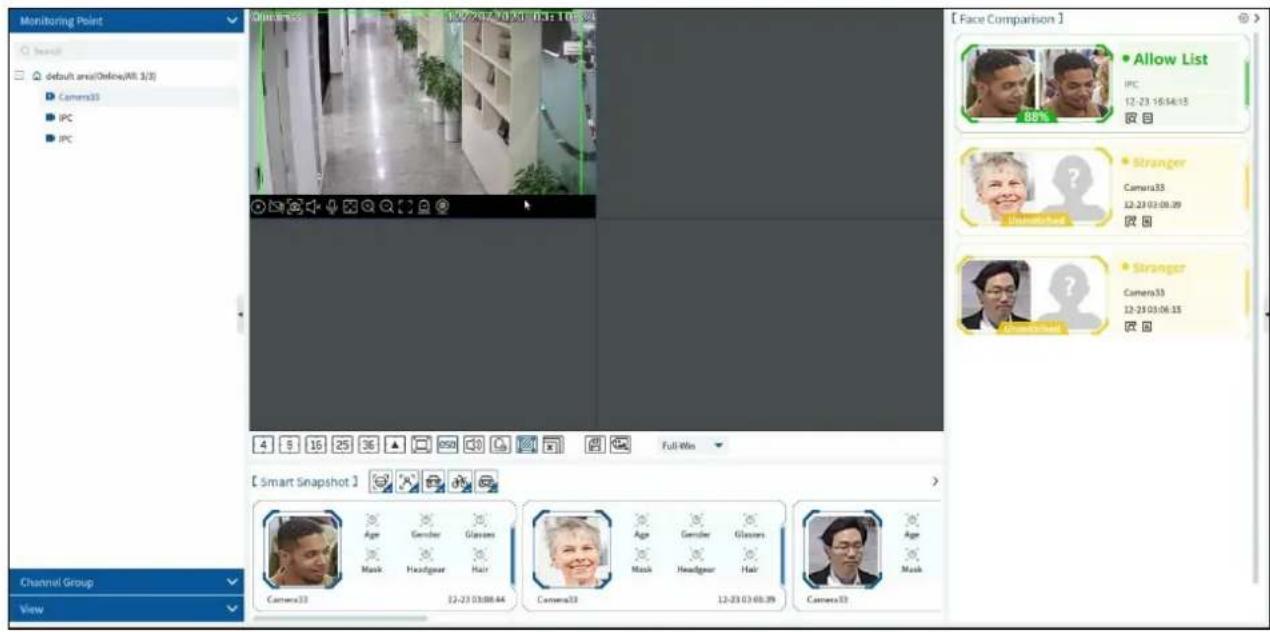
In the smart snapshot area, click the corresponding icon (face/human body/motor vehicle/non-motor vehicle/plate) to filter the display of
smart snapshots. Disable the selection and then the corresponding smart snapshots will not be displayed. Click button to quickly go to the smart snapshot retrieval interface.
![[Smart Snapshot] Age Gender Glasses Musk Headgear Hair Camera33 12-23 03:08:44 Camera33 Age Gender Glasses Musk Headgear Hair Camera33 12-23 03:08:39 Camera33 Age Musk](/content/2026/05/994503/images/63852b6549566ccfb5b79715fecd21d4ff25be8198a496a54104d94a5185711d.jpg)
For attribute display settings, please refer to snapshot attribute settings for details.
Note: If you want to view the detailed attribute/feature information of the snapshot images, you should add the AI IPC with video metadata
function and this function must be enabled first.
Quickly adding the detected target to the face database:
Put the cursor on the face snapshot and then click +. The following window will pop up. Select the group and then fill out the relevant information to add.

Click to quickly skip to the image search by image interface.
The captured picture can be exported. Click ☐ and then select the export path and then click [OK] to export
● Face Comparison Display Settings
Click 📋 on the right corner of the live interface to display the configuration window as shown below. One or more items can be selected.
Pop-up prompt: if enabled, the alarm box of the corresponding face comparison result will pop up. If disabled, the alarm box will not pop up.

Frame Holding Time: select the alarm pop-up window holding time as needed.
Statistics display: If selected, the corresponding statistical information will displayed on the top of the preview window.

● Face Comparison Records
Click ☐ to view the face comparison details. Click + to quickly add the captured face picture to the face database.

Click to quickly enter the face comparison retrieval interface. Select the camera and click [Search] to search the face comparison results.
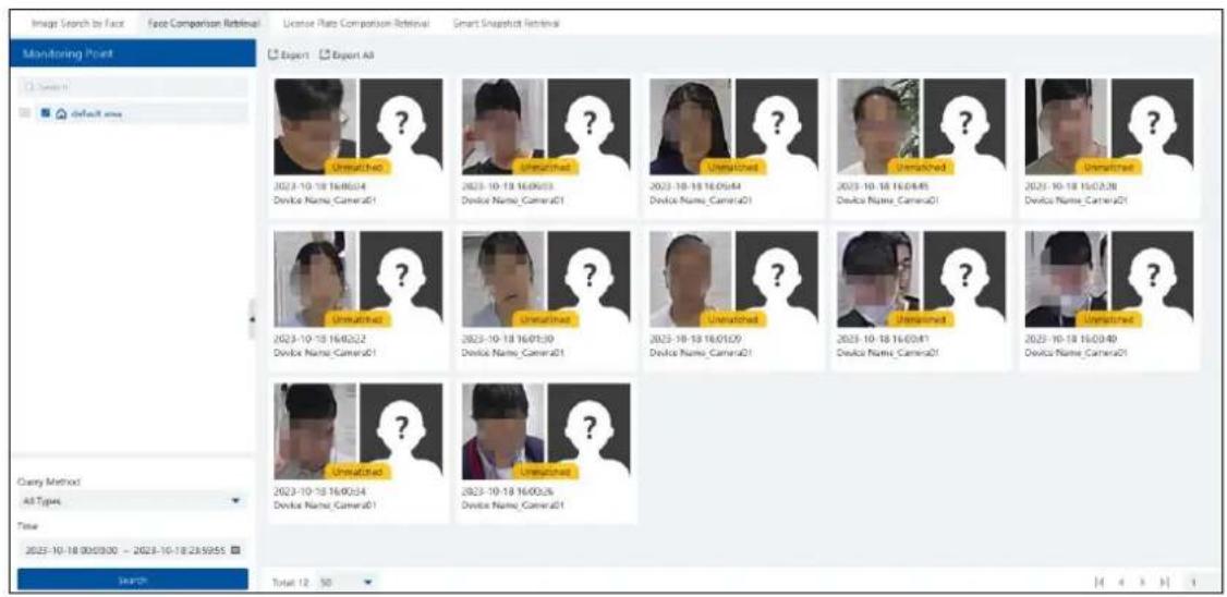
9.2.2 License Plate Comparison
If this is the first time for you to set the license plate recognition function, please follow the procedures.
Enter Group Management People & Vehicle Management Vehicle Registration Add Vehicles Task Settings View Real-time License Plate Comparison Results Search License Plate Comparison Result
- Go to People & Vehicle Management → Vehicle Registration interface. Click [Add] to add the vehicle information to Allow List or Block List.

- Click the "Task" tab to setting license plate recognition task. Select the license plate recognition camera and then click applicable scenario. Select "Vehicle deployment control" and click "OK".

- Ensure that the license plate recognition IPC has already enabled the license plate detection function.
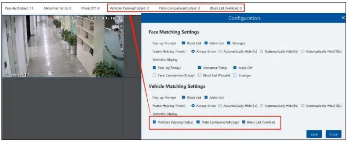
● License Plate Capture and Comparison Settings
Pop-up prompt: if enabled, the alarm box of the corresponding license plate comparison result will pop up. If disabled, the alarm box will not pop up.

Frame Holding Time: select the alarm pop-up window holding time as needed.
Statistics display: If selected, the corresponding statistical information will displayed on the top of the preview window.
● License Plate Capture Records
Click to view the license plate capture details.
![[Smart Snapshot] License Plate: 8819S Device Name_IPC 10-18 17:09:43 Detail Original Image Target Picture Channel Name : Device Name_IPC Target Type : Motor Vehicle Capture Time : 2025-10-18 17:20:32 License Plate : 8819S Playback : Property : Vehicle Color: Black Vehicle Type : Unknown Close](/content/2026/05/994503/images/615993604215bb75ccb5a12713dd2b6edc8154d57d5b1efe0b8c57a5d3c508e8.jpg)
Click to quickly go to the record playback interface.
Note: if you don't set the record schedule or record linkage is not configured for the corresponding events, no record will be searched after you enter the record playback interface.
● License Plate Comparison Records
Click to view the license plate comparison details.
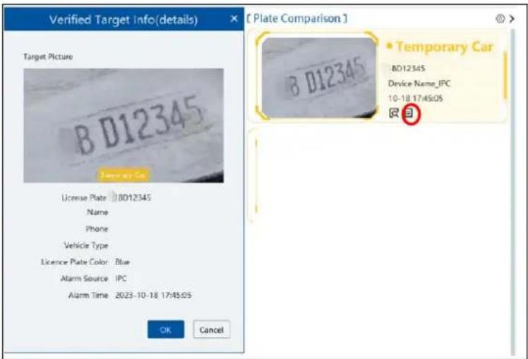
Click to quickly enter the vehicle plate comparison interface. You can search the captured vehicle plate as needed.
9.3 Plan View
In the video preview interface, select "View" on the left menu bar.
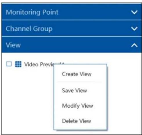
- Add View Plan:
① Right click "Video Preview 1" and then select "Create View" or click to add a new view plan. Clicking "Create View" to prompt an adding view window. Enter the view name and click [OK] to set view plan.
② Select screen display mode and then drag monitoring points or channel group to each window.
③ Click "View" on the left menu and then right click the newly added view name. Select "Save View" on the pop-up menu to save the
view plan or click on the live view interface to save the view plan.
Double click view name to call the view plan.
- Modify or Delete View Plan
Select the added view and then right click to prompt a pop-up window. Select "Modify View" or "Delete View" to modify or delete the view plan.
- Start/stop auto-switch
If multiple view plans saved, you can play these views in sequence.

Enter the dwell time (5\~3600s) and then click [Start auto-switch] to play these views in sequence. Click to view the previous view;
click to view next view; click to pause.
9.4 PTZ Control
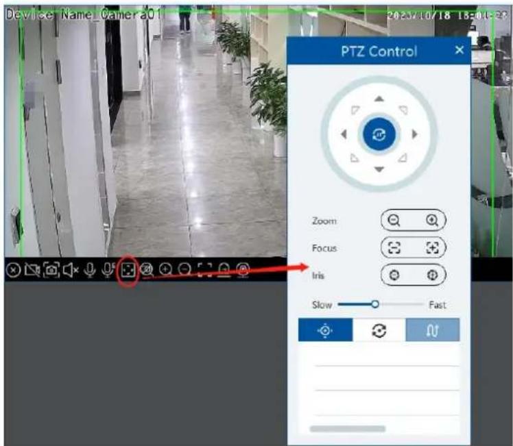
Click or right click to select "PTZ Control" to enter PTZ control interface. The directions of PTZ, zoom, focus, Iris, preset, trace and cruise can be controlled through PTZ control panel.
In the video preview interface, right click on a playing channel to select "Instant Playback" and then set the playback time to play the record instantly (the record of the channel in the past five minutes will be searched and played from that time when the record exists).

10 Record & Playback
10.1 Record Configuration
This device supports many recording types, such as manual recording, schedule recording, motion alarm recording, smart alarm recording, etc.
10.1.1 Schedule Recording
Go to Home→"Record Setting".
| by Time | by Event | by Tag Management | Record Backup | Search Picture | Record Setting | |||||
| Area | Schedule Setting | |||||||||
| Channel Name | Stream Type | Record Schedule | Audio | Recording Before Alarm(s) | After Alarm Timet (s) | Expire Timet(day) | Offline Record | |||
| Search | *Device Name_IPC | Main Stream | 7*24 | Open | 0 | 60 | Never Expire | Open | ||
| default area | *Device Name_IPC | Main Stream | 7*24 | Open | 0 | 60 | Never Expire | Open | ||
| *Device Name_IP Camera01 | Main Stream | 7*24 | Open | 0 | 60 | Never Expire | Open | |||
| *Device Name_IP Camera03 | Main Stream | 7*24 | Open | 0 | 60 | Never Expire | Open | |||
| *Device Name_Camera01 | Main Stream | 7*24 | Open | 0 | 60 | Never Expire | Open | |||
| *Device Name_IPC | Main Stream | 7*24 | Open | 0 | 60 | Never Expire | Open | |||
To set schedule recording, select the channel, stream type and schedule. Then Click [Apply] to save the settings.
Recording Before Alarm: set the time to record before the actual recording begins.
After Alarm Time: set the time to record after the actual recording is finished.
Expire Time: set the expiration time for recorded video. If the set date is overdue, the recorded data will be deleted automatically.
Offline Record: When the IPC/NVR is disconnected with the storage server, the IPC/NVR starts offline record. After the network is connected again, the offline record of IPC/NVR stored on the SD card or HDDs will automatically transfer to the storage server.
Note:
- The time of the IPC/NVR must be the same as the storage server.
- A maximum of 8 channels can simultaneously transfer the offline records to the storage server.
- Due to the limit of the storage capacity, the previous records of the IPC may be overwritten if the disconnection time is too long so that only a part of records can be replenished.
- Only support the most recent 12-hour record replenishment.
- To set schedule:
① Click the "Schedule Setting" tab to go to the following interface.
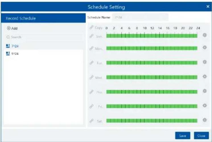
② Click [Add].

③ Enter the schedule name.
④ Set the schedule. Drag the mouse on the timeline to add or erase the time period. Click to manually set the time period. Put the cursor on the set schedule name and then a deletion icon will appear. Click it to delete the schedule.
10.1.2 Alarm Linkage Recording
① Go to Home→Device Setting interface. Select the desired device to enable the alarm event and set schedule.
② Go to Home→Alarm Center→Alarm Linkage as shown below. Select alarm type, enable record, set linakage channel and set the schedule.
③ Click [Apply] to save the settings.
![Alarm Log Search Alarm Setting Alarm Type All ON RE OFF record output Area Audio Present Record OFF Null Camera01 Null Server Monitoring Point [Device Name_Camera01] Record Linkage Setting Enabled Selectable Device 1/5 Selected Device 0/0 Search default area Device Name_Camera01 Device Name_IP Camera01 Device Name_IP Camera02 Device Name_IPC Device Name_IPC Device Name_IPC Device Name_IPC NO choice OK Cancel](/content/2026/05/994503/images/bf1871ba14766be8ddc52707ba07e3e4f4bcc0b343fc3e9f25ce4160f99670e8.jpg)
10.2 Playback
In the main menu interface, click "Record Playback" to go to record playback interface. Record files saved on the HDD/ SD card of the devices and storage server can be played.
There are three types of playback: normal playback, smart playback by face, smart playback by license plate.
10.2.1 Normal Playback
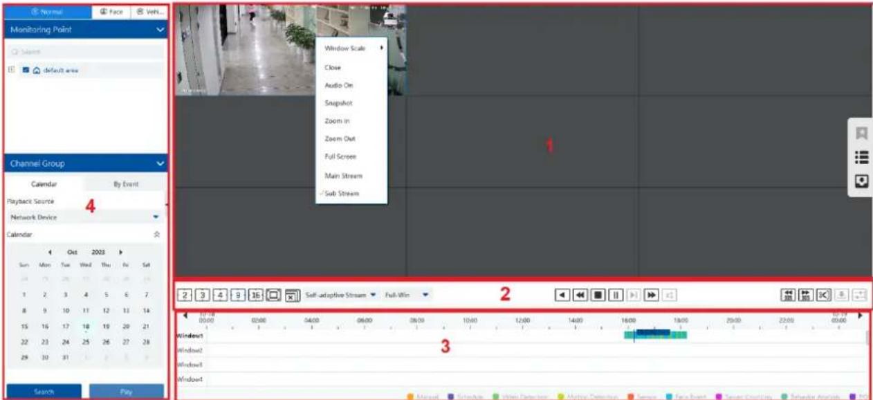
Area Description
| Area | Description | Area | Description |
| 1 | Playback area | 3 | Record timetable area |
| 2 | Toolbar | 4 | Time and event search area; resource area |
Toolbar on Playback Window
| Button | Description | Button | Description | ||
| [003K] | Stop viewing |  | Zoom in | ||
 | Audio on/off |  | Zoom out | ||
 | Snapshot | [WDY0] | Fit to window | ||
Button Descriptions of Area 2:
| Button | Description | ||||
| [7KB4] |  |  | [723Z] | Screen display mode button. | |
| Full screen | |||||
| Close all window viewing | |||||
| Rewind | |||||
| Low speed playback | |||||
| Stop | |||||
 | [ZXTW] | Play/Pause | |||
| [54ZZ] |  | Next frame. In the playback mode, click the pause button and then click this button to play frame by frame. | |||
 |  | Click it to select playback speed. | |||
| x1 | Click it to restore normal playback | ||||
| [24SB] |  | Forward 30s or backward 30s | |||
 |  | Set backup time | |||
 |  | Start backup | |||
 |  | Synchronous playback or asynchronous playback | |||
Clip and backup:
Click to enter the edition status. On the recorded timescale, select the start and the end time or right click on the timescale and
then select [Change backup time] to set the backup start time and end time. After that, click to enter the record backup interface to view the backup file list.
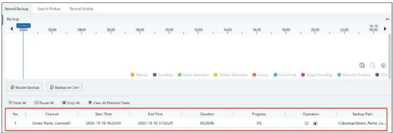
Right-click button menu
| Menu | Description | Menu | Description |
| Close | Close viewing | Zoom out | Zoom out the current image |
| Audio On/Off | Audio on/off | Full Screen | Click to enter full screen mode |
| Snapshot | Snapshot | Sub stream | Switch to sub stream playing |
| Zoom In | Zoom in the current image |
Other buttons
| Button | Description | Button | Description |
| [20HC] | Add tag |  | Event list |
 | Backup |
Set record date, record type (for some devices, "Main Stream" can be selected to play the record, or the record will be played by sub stream if unselected) and the record playback source in the playback interface. Drag the camera on the right side to playback window for playing or double click a desired channel to play or click [Search]to search the record files and then click [Play] to play.
Playback record type includes manual recording, motion detection recording, schedule recording, sensor recording, target counting recording and behavior analysis and so on.
In the timetable, different color bars stand for different record types. For instance, yellow bar stands for motion recording data; blue bar stands for schedule recording data; red bar stands for sensor record data, etc.
The time scale can be zoomed in by clicking + and the time scale can be zoomed out by clicking - .The time scale can be restored to 24 hours by clicking 24 . When the time scale is zoomed in, drag the timeline to see the time spots.
Synchronous Playback: in a certain time, all channels playback its record at the same time together; if one channel has no record data at this time, this channel will wait.
Click on the toolbar in the playback interface to go to the synchronous playback interface.
In synchronous mode, one camera can only have one playing window. All cameras' record information can be viewed at the same time.
When playing record file in synchronous mode or asynchronous mode, clicking 📄 or 📋 will be useless unless all the playback windows are closed.
Asynchronous Playback: when playing some channels' record at the same time, each channel is independent from the others and each channel's playback time is different.
Click to go to the asynchronous playback interface. Please play the record according to the ways introduced as the above. The record bar in asynchronous mode is as below.
10.2.2 Smart Playback by Face
For the added face recognition NVR, you can play back by searching face.

Clicking on 📄 Face enters the above interface. Select the face recognition NVR and then click "Upload" to add a face picture. You can add the face picture from the USB flash drive, target picture or group. After that set the start and end time, max. number and similarity and then click [Search] to search the records.
Add a face picture from the USB flash drive: Click "Upload" to select the desired face picture in the USB flash drive and then click [OK] to save the settings.
Add a face picture from the target picture: Select cameras, search resource, query method and time to search targets. Then select the target and click [OK].
Add a face from the face database:
- Click the "Group" tab.
- Select the face picture from the person list.
- Click [OK] to save the settings.
The picture must be added to the corresponding list in advance, or no picture can be searched. Refer to Chapter 6 Group Management for details.
Note: The record source is from the HDD of the face recognition NVR. The comparison record of this person must exist in the HDD, or no record can be played.

10.2.3 Smart Playback by License Plate
The vehicle records can be searched from the NVR. The setting steps are as follows:
- Select the NVR.
- Enter the license plate number to select the plate from vehicle database of NVR.

Network device: select the record source from the NVR.
10.2.4 Playback by Time
① Go to Home→By Time interface.
② Select channel (or monitoring point), set the start time and the end time, select the playback source and then click [Search].
![Monitoring Point Search default area Playback Source Network Device Time 2023-10-18 00:00:00 - 2023-10-18 23:59:55 Search Slice Per Day Record Backup To Storage Playback 2023-10-18 15:51:56 Total: 1 Show all [4 < > ] 1 /1Page](/content/2026/05/994503/images/7416e82547b48731013c97f45c5afbd833d897297774eb27f76cc846dd06d675.jpg)
③ Click to play the record.

Click Button on the top right corner to play in full screen mode.
Double click the image to switch to slice search mode by hour.
Double click an image to switch to slice search mode by 5 minutes. Click "Slice Per Day" or search it again to return to slice search mode by day.
Record Backup: The selected time slice will be quickly backed up by clicking the "Record backup" tab next to "Slice Per Day".
To Storage Playback: The selected time slice will be quickly played back in the storage playback interface by clicking this button.
10.2.5 Playback by Event
① Go to Home→By Event interface.
② Select the desired monitoring point, set the record source, the start time and the end time and then check events.
| By Time | By Event | By Tag Management | Record Backup | Search Picture | Record Setting | |||||||
| Monitoring Point | Before the event | 0 | x | To Storage Playback | Device name/Time/Event type | |||||||
| Search | No. | Name | Start Time | End Time | Duration | Type | Playback | Record Back... | Backup Str... | Backup on Day | ||
| default area | 1 | Device Name_Camera01 | 2023-10-18 19:33:38 | 2023-10-18 19:34:06 | 00:00:28 | Face Event | Main Str... | |||||
| 2 | Device Name_Camera01 | 2023-10-18 19:33:38 | 2023-10-18 19:34:16 | 00:00:38 | Face Event | Main Str... | ||||||
| 3 | Device Name_Camera01 | 2023-10-18 19:33:30 | 2023-10-18 19:35:07 | 00:01:37 | Motion Detection | Main Str... | ||||||
| 4 | Device Name_Camera01 | 2025-10-18 19:32:18 | 2025-10-18 19:32:37 | 00:00:19 | Face Event | Main Str... | ||||||
| 5 | Device Name_Camera01 | 2025-10-18 19:32:18 | 2025-10-18 19:32:54 | 00:00:36 | Face Event | Main Str... | ||||||
| 6 | Device Name_Camera01 | 2025-10-18 19:31:45 | 2025-10-18 19:32:42 | 00:00:57 | Motion Detection | Main Str... | ||||||
| 7 | Device Name_Camera01 | 2025-10-18 19:31:25 | 2025-10-18 19:31:43 | 00:00:18 | Motion Detection | Main Str... | ||||||
| 8 | Device Name_Camera01 | 2025-10-18 19:30:56 | 2025-10-18 19:31:14 | 00:00:18 | Motion Detection | Main Str... | ||||||
| 9 | Device Name_Camera01 | 2025-10-18 19:30:31 | 2025-10-18 19:30:50 | 00:00:19 | Face Event | Main Str... | ||||||
| 10 | Device Name_Camera01 | 2025-10-18 19:30:04 | 2025-10-18 19:30:23 | 00:00:19 | Face Event | Main Str... | ||||||
| 11 | Device Name_Camera01 | 2025-10-18 19:30:03 | 2025-10-18 19:31:10 | 00:01:07 | Face Event | Main Str... | ||||||
| Reverse Manual Video Detection Sensor Target Counting POS Key Word Search Total: 439 SD | ||||||||||||
③ Click [Search]. The searched record data will be listed. Click [To Storage Playback] to play the record in the storage playback interface;
click to play the record in a small playback window; click to back up the record data.
10.2.6 Playback by Tag
Note: Record tag cannot be added to the record from the device.
① Go to Home→Record Playback interface.
② Select a channel and put the cursor on the right center. Then a tag icon ( ★ ) will appear. Click this icon to add tag.
③ Go to Home→By Tag interface. Select the start time and click [Refresh] to search the added tags.
④ Click ▶ in the playback column to play the record.

10.3 Record Backup
In the main menu interface, click "Record Backup" to go to the backup interface. The setting steps are as follows:

① Select the desired monitoring point.
② Get records from device or storage server.
③ Select date and event type.
④ Drag the mouse on the recorded time period to set the start time and the end time of backup. Then click [Record Backup].
⑤ The backup progress will be seen during backing up the record. Click to pause; click to stop backing up the record;
Additionally, you can start/pause/stop all backup tasks or clear all finished tasks in this interface.
"Backup on device": This function is applied to the added NVR devices. Search the record from the HDD of the NVR in this interface and then insert a USB storage device into the USB port of the NVR and then click this button. Then the recorded files will be backed up to the USB storage device remotely.
10.4 Search Picture
In this interface, pictures stored on the SD card/HDD or storage server can be searched and viewed.
These snapshots saved on the storage server or SD card /HDD must be triggered by alarm events so that they can be searched.

-
Select the device and playback source.
-
Set the start time and the end time.
-
Click [Search]
Click the searched picture to zoom in. Click it again to return to its original size. Check the selected picture and click "Export" to export the selected pictures.
11 Alarm Management
11.1 Alarm Server Configuration
Alarm server is in charge of receiving and recording alarm information of connected devices and then sending the alarm information to the relevant user terminal system or devices in accordance with prior alarm settings. There is a default alarm server.
Go to Home→Add, Edit or Delete Device →Alarm Server interface to view the online status of the alarm server. If it is not online, please check its network connection.
11.2 Alarm Configuration
① Go to Home→Device Setting interface.
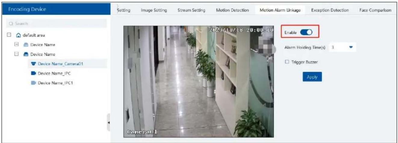
Select the desired device to enable alarms (refer to the user manual of the corresponding device for the detailed settings).
② Go to Home→Alarm Center→Alarm Linkage interface.

Select area, alarm type and then enable alarm linkages.
All ON: enable all alarm linkages of the current alarm type and area (schedule excluded).
All OFF: disable all alarm linkages of the current alarm type and area (schedule excluded).
Select beside the device name and select "ON" to enable all alarm linkages of the device (schedule excluded).

Select beside the title (like record) to enable record linkage of all devices (schedule excluded). Select "Link to itself (On)" to quickly select the camera itself as the record camera.

The alarm linkage settings of preset, record, alarm preview, snapshot, alarm output and TV Wall are the same with each other. Here take record linkage for example to introduce the setting steps.
![[*Device Name_Camera01] Record Linkage Setting Enabled Selectable Device 1/6 Selected Device 0/1 Search default area Device Name_IP Camera0 Device Name_IP Camera0 Device Name_IPC Device Name_IPC Device Name_IPC Device Name_IPC1 OK Cancel](/content/2026/05/994503/images/44e52de97f9ecc896017ce8242a37b40e0b863d20852c1803f92847587fb5875.jpg)
Check the selectable channel and click > to select the channel; check the selected channel and click < to remove this channel;
click to select all channels; click to remove all selected channel.
After the channels are selected, check "On" and then click "OK" to save the settings.
Note: For TV wall alarm linkage settings, multiply TV wall pop-up windows can be linked to one channel.
Before checking voice broadcast, please upload the voice first (See Audio Uploading Settings for details).
Before checking Email, please set the sender's email address and the recipient address first (See Email Settings for details).
Before checking SOP, please set the SOP first (See SOP Settings for details)
③ Set alarm schedule. Select the schedule of the desired device. 7*24 or 5*24 is the default schedule. Other schedules need to be set in
advance. Click the "Schedule Setting" tab to set (See Schedule Recording→To set schedule for details).
Note:
-
For the alarm linkage items related to face recognition, you can set them separately, including face comparison alarm linkage, stranger alarm linkage, block list alarm linkage.
-
For the combined alarm of DVR/NVR, you can configure the alarm linkage items in the platform. If the combined alarm is set after the NVR/DVR is added to the platform, the platform cannot automatically receive the combined alarm data. Please reboot or reconnect your NVR/DVR and then the platform will display this device under the alarm type of "Encoding device-combined alarm".
11.3 SOP Settings
Click the "SOP Setting" tab in the alarm center interface to go to the following interface as shown below.
- Click "+" to add a SOP name.
- Click "Create" to create a SOP action.
- In the alarm linkage settings interface, select the alarm event and enable SOP of the relevant device.
-
Click to extend the alarm list.
-
Click to handle the alarm. Select the SOP action and then click "Save Process". After that, choose disposition and enter remark as needed.
The disposition includes: False alarm, true alarm, customer test, technical event, service test.
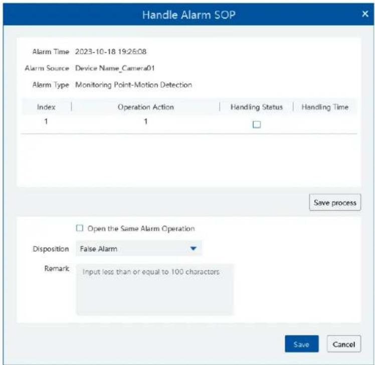
After the alarm is processed, the alarm handling status and disposition will be shown as below.

If "SOP Filter" is enabled, the alarm events of the channel set the SOP will be listed.
11.4 Alarm Task Settings
In this interface, you can set the leaving alarm task.
Leaving alarm: When someone leaves the predefined area and doesn't come back within the set time duration, the system will perform alarm linkages.
To set a leaving alarm task:
- Enter the Alarm Task Setting interface.
- Click [Add] to add the alarm task.
- Set the task name, interval time, schedule and choose the camera.
- Multiple cameras can be added to an alarm task.

- Set the alarm linkage items. In the alarm linkage settings interface, select the alarm type as "Alarm task-Leaving Alarm". Then enable the desired alarm linkage (like "Alarm preview") and set the schedule.
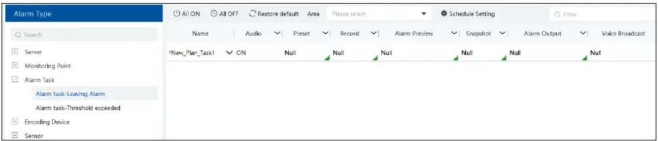
- Go to the Device Setting interface to enable Intrusion and set the detected area.
Note:
- The selected camera must support and enable intrusion function, or leaving alarm will not take effect. If the camera supports vehicle/people classification, please check "Human" as the detection target.
- After the leaving alarm task is set and intrusion is enabled for the camera, when someone enters the predefined area and stays there, this person will be judged as "On Duty" so that leaving alarm will not be triggered and the intrusion alarm will not be displayed on the alarm list; but when this person leaves and doesn't return within the set time duration (interval time) or no one appears in the set time duration, leaving alarm will be triggered.
11.5 Email Setting
Alarm information can be received by the specified Email address if the Email parameters have been set in advance.
Click Home→Alarm Center→Email Setting to go to the following interface. Add the sender and recipient's email information here.

In the sender's Email information area, fill out the corresponding information and then click "Apply" to save the settings.
Clicking on the [Add] button adds the recipient information.
After that, in the alarm linkage setting interface, you can trigger Email.

11.6 Alarm View
Havingset the alarm preview linkage, the alarm view window will prompt when an alarm is triggered.
![[Device Name_Camera01] Alarm Preview Linkage Setting Selectable Device 1/6 Selected Device 0/1 Search default area Device Name_IP Camera0: Device Name_IP Camera0: Device Name_IPC Device Name_IPC Device Name_IPC Device Name_IPC1 OK Cancel](/content/2026/05/994503/images/06a28d2d1a06ca88d6de0ef1e1634c803f35004dd880a92b081514596e70a588.jpg)
In the alarm preview interface, you can select multi-screen display mode by right clicking on the preview window as shown below.

Click 📄 on the bottom right corner to expand the alarm list as shown above. Hover the cursor on the top of the alarm list and then a bidirectional arrow will appear. Drag the alarm list up or down to extend or shrink the alarm list.
Click or to play the record or captured images.
Right clicking on an alarm item displays a menu. Click "Alarm Preview" to jump to the alarm preview interface.

11.7 Alarm Log
Alarm logs can be searched and exported by going to Home→Alarm Center→Alarm Log interface.
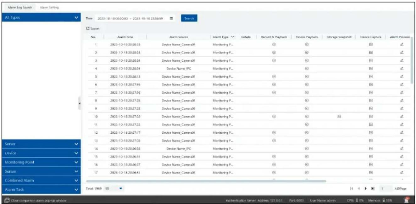
Click to play the record; click to open the snapshot search window as shown below.
11.8 Manual Alarm Out
Click "Manual Alarm Out" tab to go to the following interface.

Select the camera, set the alarm holding time and then click [Trigger] to manually trigger the alarm out of the camera; click [Clear] to manually turn off the alarm out of the camera.
12 E-Map
The e-map service is used to store the e-map information of the system. The client landing anywhere can share the same e-map.
12.1 E-Map Settings
12.1.1 Create E-Map
Go to Home→E-Map Setting interface. Click [Create Map] to create a map.
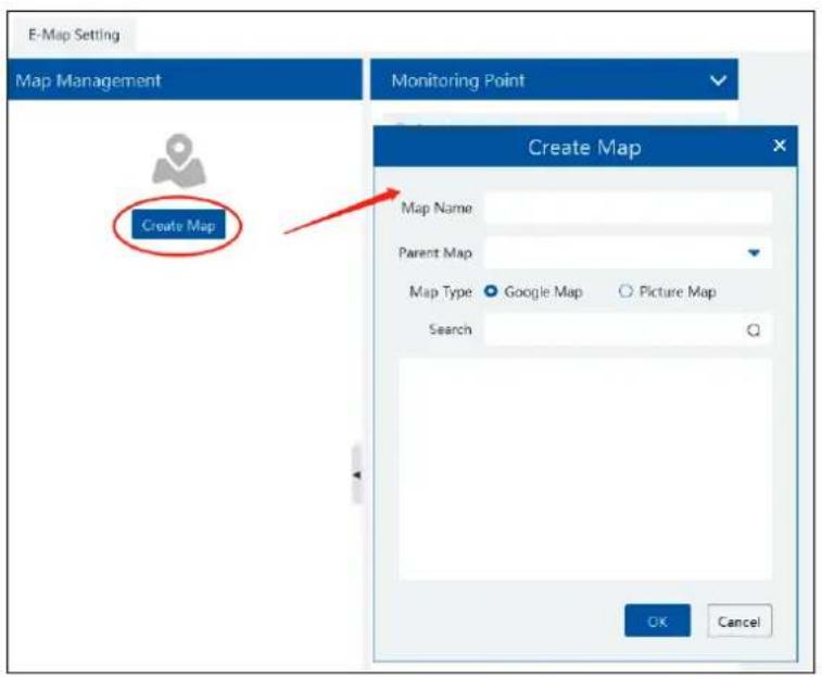
Enter E-map name, select parent e-map and map type. Then click [OK] to save the settings.
12.1.2 Add Hotspot
The hotspots include monitoring points and sensors. Drag a hotspot to the corresponding area on the map as shown below.

Put the cursor on the map name and then some icons will appear. Click + to add its sub map. Click 🔔 to modify the map name and change its parent map.

Click to delete the added map.
Click at the bottom of the interface and then right click on hotspot alarm item. Select "E-Map" to quickly skip to E-map monitoring interface.

12.2 E-Map Monitoring
Go to Home→E-Map Monitoring interface. Select a window on the right and then double click the monitoring point to view the real-time image.

Switch to Alarm E-Map: if "Yes" is selected, the system will automatically switch to the E-map on which the alarm occurs.
Auto Alarm View: if you select "Yes", the monitoring video will automatically pop up on the right window when an alarm is triggered.
Put the cursor on the preview window (right panel) and then a toolbar will display. Clicking on Ⓧ closes the preview. Click "Close All
Stream" to stop all previews. The preview window will be overlaid on the map by clicking "Overlap".
In addition, click [Filter Alarm Type] to filter the alarm type.
If multiple cameras need to play, you can drag the window on the right panel to the right. Then an independent monitoring interface will display. You can choose the screen display mode as needed.

13 TV Wall
Click at the bottom right corner and then select "TV Wall Guide" to quickly set the TV Wall as shown below.

flowchart
graph TD
    A["Add Device"] --> B["Add TV Wall"]
    A --> C["TV Wall System Setting"]
    A --> D["TV Wall Task Settings"]
    C --> E["TV Wall View"]
Please follow the guide in sequence to quickly set the TV Wall.
13.1 Add Device
13.1.1 Add Decoder
Decoder is used to decode the video signal transmitted by the transfer server. The decoding output is a standard video signal. The decoder is necessary for decoding videos on the TV wall.
Go to Home→Add, Edit or Delete Device→Decoder interface.

The steps for adding decoders are the same as the setup for adding encoding devices (see Add Encoding Device for details).
13.1.2 Create and Connect Decoder
The decoder which needs to be connected to the platform must be the master decoder and in platform mode. Login the web client of the decoder as shown below.
Go to Basic Settings→ System Settings to check the user permission and running mode of the decoder and make sure its user permission is master and its running mode is platform. Then apply the settings and restart the decoder.
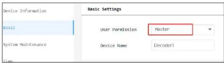
The decoder will not be online until it is bound to a TV wall. Please create a TV wall first and then bind the decoder to the TV wall.
13.2 TV Wall Management
◆ Create TV Wall
Go to Home→TV Wall → TV Wall View. Select a TV wall server and then click + to create a TV wall.

Select the TV wall server and then set the TV wall name, display matrix and TV wall number.
Note: The TV wall number cannot be used repeatedly.
Click [Draw] to draw the TV wall layout manually.
After that, click [Next] to bind decoders.
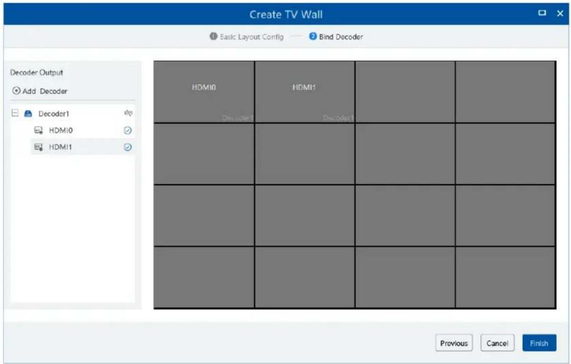
On the left list, click to bind the decoder. If there are no decoder to bind, you can click Add Decoder to quickly jump to the decoder adding interface and then add the decoder as needed. After you clicking , it needs several seconds to connect the decoder. After the decoder is connected, the output will be listed under the decoder name.
If you want to unbind the decoder, click behind the decoder name to unbind it.
Drag the output to the window to bind the output and the window. After that, click [Finish] to save the setting.
To change the output binding, select the TV wall and click , select to modify. Click to delete the TV wall.
13.3 TV Wall System Settings
13.3.1 Channel Number Settings
Channel number configuration: set the channel number and make the channel convenient to be controlled by the network keyboard controller. Users can export these channel number in this interface.
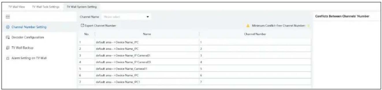
13.3.2 Decoder Setting

Display red box: when the decoding channel triggers alarm, a red box will show on the TV Wall.
Display ID: the channel ID will be shown on the channel decoded by the decoder
13.3.3 TV Wall Alarm Linkage Settings
Click "Alarm setting on TV Wall" and then the alarm closing time can be set. If "Automatically closing alarm on Wall" is selected, you can set the time that TV wall alarm automatically turns off. The alarm preview window will automatically turn off the alarm linkage video according to the set time until next alarm is triggered. If not selected, you need to close the alarm preview window manually.
13.4 Video Preview
◆ Create a plan
Click beside the TV wall name or click [Create Plan] to create a new plan for the created TV wall.

Double click the plan name to show the plan.
Drag the monitoring points to the corresponding window respectively to decode image. Then click to save the plan.
◆ Configure Plan
Double click the set plan to display on the left window as shown below. Drag the monitoring point to the window to play.

◆ Toolbar Menu

- Screen mode: 1\4\9\16\25\36 screen mode is optional.
- Open Window: Click this icon and then drag on a window to open a window on it. The window can be dragged to anywhere on the big window. Click the opened widow and then drag the blue side of the window to zoom in/out it.
Click this icon again to stop opening other windows.

natural_image
Simple geometric diagram of a square with labeled dimensions (100 and 200) and no text or symbols beyond measurement markers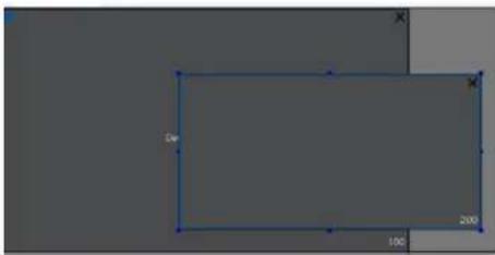
natural_image
Pure geometric shape with dimension labels (100, 200) and 'De' annotation, no readable text or symbols beyond measurement markers- Show/hide ID: show or hide all ID number (including all channel numbers of the multi-screen display window).
- Show/hide window ID: show or hide the ID number of all windows (Note that the channel numbers of the multi-screen display window are not displayed).
- Click [Save] to save the current plan.
Select a window assigned a monitoring point and then press the right mouse and drag to another window to copy monitoring point to it.
Right-click Menu

- Screen display mode:1\4\9\16\25\36 screen mode is optional.
- Preview: click it to view the video.

- Save as Alarm Window: click it to save the current window as an alarm window. The alarm linkage image will be displayed in this window. Go to Home→Alarm Center→Alarm Setting interface. Select TV wall linkage item to set alarm linkage.

- Set as Playback Window: when decoding images, click this menu to play the records of the current channel (the record source is the current record source).
- PTZ Control: click this menu to prompt a PTZ control panel of the current decoding window. Direction control, zooming and focusing, Iris control, speed, preset, track and cruise calling can be operated through this control panel.
- Stop Decoding: click it to stop decoding the current image.
- Play audio: click it to play live audio. Click "Stop audio" to stop playing.
◆ Auto-Switch Group
- Create Auto-Switch Group
① Click Auto-Switch Group under the screen and then click ⊕ to create auto-switch group.
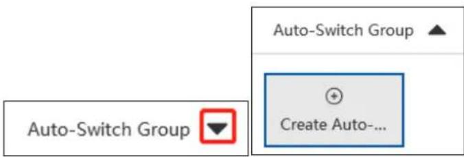
② Select "Auto-Switch Window" to select the window group.

③ Click [Next] to select the auto-switch channel group.

④ Enter auto-switch name and dwell time.
2. Execute auto-switch

Click to execute auto-switch. The specified channel images will be played in the specified windows in sequence. Click to stop playing the current auto-switch group.
3. Modify or delete auto-switch
Right click on the auto-switch group name and select Modify or Delete to modify or delete the auto-switch. Or click and then select the corresponding icon to modify or delete the auto-switch.


◆ Auto-switch plan
1. Create auto-switch plan
Click behind the TV wall plan name and then click to set the auto-switch. Click "Join in" to select the plan. Then set dwell time and click [OK].

2. Start/stop auto-switch

Click behind the TV wall name to start auto-switch plan. Click to stop the auto-switch.
3. Modify auto-switch plan
Click again to modify the auto-switch plan.
Note: If the current auto-switch plan needs to modify, please stop it first.
13.4.1 Decoder Input
Go to Home→TV Wall Management→Decoding on TV Wall→Decoder Input. Drag an input to a window to execute decoding.
13.4.2 Playback
◆ Playback on TV Wall
Click "Record", select playback source and time, check the alarm events and then drag the cameras (or channels) to a window to search and play the records.

◆ Playing control

During playback, the record can be controlled by the above buttons.
Note: The frame rate per second will be the same as the set frame rate of the device (Home→Device Setting→Stream Setting→Frame
Rate).
Right-click menu
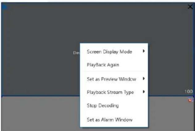
- Screen Display Mode:1\4\9\16\25\36 screen mode is optional
- Save as an alarm window: click it to set the current window as an alarm window. The alarm linkage image will play in this window. Please go to Alarm Center→Alarm Setting interface. Select the alarm type, link the TV wall and set the schedule first.
- Save as preview window: the current camera or the historical camera is optional. If the current camera is selected, the window will display the live video of the current camera in the record page. If the historical camera is selected, the window will display the live video of the camera decoded in this window last time.
- Playback stream type: main stream or sub stream is selectable.
- Stop decoding
The following picture is an example of TV Wall.

natural_image
Collage of 20 industrial and factory interior photos showing factory layouts, workers at stations, and assembly lines (no visible text or symbols)13.5 TV Wall Task Setting
Go to Home→TV Wall Management→Task Setting. Select the TV wall you want to set tasks. Then click "Create Task". Select plan name, enter task name, set run time and enable plan task.
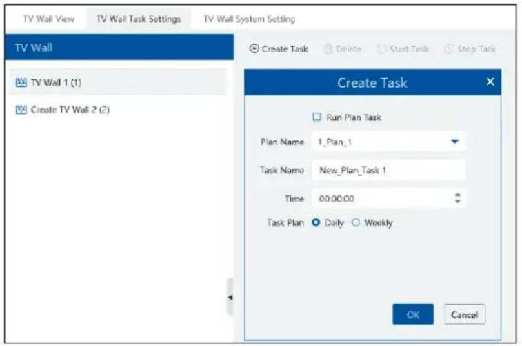
Click "Start Task" to start the task. Click "Stop Task" to stop this task.

Modify or delete task

Click or to modify or delete the task.
Check the task under the TV wall and then click [Delete] to delete the task as shown below.

13.6 TV Wall Backup
When importing the former system configuration files to the new version, the TV wall configuration file will not be imported together. So you need to import the TV wall configuration file separately.
Click [Backup TV Wall] in the last version to back up the TV wall configuration files. Then click [Restore TV wall] in the new version to restore it.
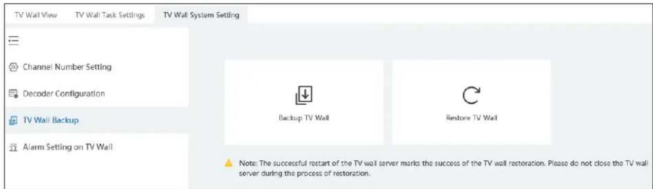
14 Target Counting
14.1 Task Management
- Enable "Target Counting" function of the IPC.
Note: the added camera must enable target counting function.
IPC with Target Counting function

- Go to Home→Target Counting interface. Clicking on

enters the following interface. Double click the camera with the target
counting function and then select "ON". After that, click [Apply] to save the settings.

14.2 Real-time Statistics
Go to Home→Target Counting→Real-time Statistics. Double click the camera with the target counting function to view the live image. The camera will automatically count the number of people/motor vehicle/non-motor vehicle crossing the predefined line and the system will automatically analyze the traffic flow trends.
Before view the statistics, please go to Home→Resource Management→Device Setting→Target Counting interface to set the alert line, entrance/exit, detection target, etc.

line
| Time | Total Traffic Flow | | -------- | ------------------ | | 09:00 | 0 | | 11:00 | 5 | | 12:00 | 4 |Please select the type as needed to view the flow trend. Click C Refresh to refresh the current statistics.
Set the auto refresh interval: The system will automatically refresh the statistics at regular intervals.
In the above interface, you can view the statistics of people/vehicles entering or exiting. Scroll down to view the traffic flow statistics via pie charts and tables.

other
Proportion of Human&Vehicle Entry in Each Channel | Location Name | Type | 00:00-01:00 | 01:00-02:00 | 02:00-03:00 | 03:00-04:00 | 04:00-05:00 | 05:00-06:00 | 06:00-07:00 | 07:00-08 | Subtotal14.3 Heat Map
Go to Home→Target Counting→Heat Map interface.
Please create a map first.
Drag the camera with the target counting function to the specified area.
Put the cursor on the camera icon and then you will see the detailed flow statistics.
![[ Flow Summary Statistics ] Statistical type Total No.(IN) Passenger flow type Human auto refresh 1 minute Refresh 5 Total No.(OUT) Max. Daily Number (Inside) Current Number (Inside) 1 Hotspot map Device Type Smart IPC Office Engineering Department WC Female WC Male Conference Room Exit Front Door Elevator Corridor Conference Room Confermoc Room Service Department Commerce Department Domestic Marketing Department Corridor Reception Deck Test Department IPC1 Lobby Corridor Test Room Device Name Camera01 Co-Department Financial Department International Marketing Department HR Department General Manager Room Warehouse E-Map Setting Traffic Ranking of Each Monitoring Point Ranking Monitoring Point Name Traffic Flow Prefer 1 IPC1 5 2 Device Name Camera01 0](/content/2026/05/994503/images/56a4824976a7614157e766d2e2df76eda9cd0c757505a2a020ae5cfa682071dc.jpg)
The deeper the red color is, the more targets (human/vehicle) gather there.
14.4 Historical Statistics
Go to Home→Target Counting→Historical Statistics. In this interface, the statistic results in a long period of time can be searched which can be shown in the table or curve chart. Additionally, the statistics of different targets can be viewed here.

line
| Time | Total Traffic Flow | | ---- | ------------------ | | 2023-10-19 | 5 | | 2023-10-18 | 4 | | 2023-10-17 | 1 |14.5 Flow Control
Flow Control: Control the people/vehicles entering or exiting in a specified area to avoid overcrowding. When the people/vehicles stay in the specified area exceeds the threshold, the alarm will be triggered and no entry icon will display.
Click Home→Target Counting→Flow Control to enter the following interface.
Click to add a task. Multiple tasks can be added as needed.
![[ Task list ] Real-time Statistics Heat Map Historical Statistics Flow Control Add Task Task Name Task 01 Maximum Threshold Type Human Schedule 7*24 Add Task Selectable Device 0/1 Selected Device 0/0 Search default area IPC1 No choice OK Cancel](/content/2026/05/994503/images/887570c468c60fa17ac1d2a3a9c0e2e34170b9360885034452bcc2332f01117e.jpg)
Then the available number and inside number can be viewed as below.
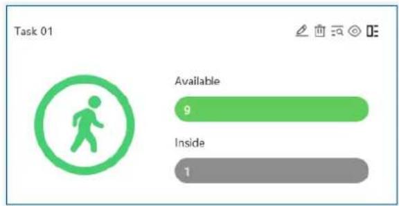
Click to view the quantities of the people/vehicles entry and exiting.
Click to enter the flow control preview interface.

In the above interface, you can switch the camera and view the image. When the people/vehicles inside exceed the threshold, the icon will turn red.
Click on exits the current page.
15 Visitor Management
The system provides an entire process for visitor management. You can manage visitors through access control devices and this system.
15.1 Add Access Control Devices
You can add a face recognition & access control terminal to manage visitors.
Click Home→Resource Management→Add, Edit or Delete Device→Encoding Device to add face recognition & access control devices.
Note: Access control devices includes face recognition & access control terminal, face recognition IPC, face recognition NVR, but the face recognition IPC and NVR only can record the access records of the visitors. Please contact our technical supports to get the detailed models.
15.2 Apply for a Visit
There are two ways to apply for a visit.
- Go to Visitor List→Visitor Registration interface. Click "Visitor Registration" to add a visitor.
Fill out the information of the visitor and then select the visitee as needed.

Select the access point.

Visitor Permission Group Settings:
Click "Set the visitor permission group" to skip to the permission management interface. Click "Visitor Permission Group" to set the permission of visitors as shown below.

Click [Add] to add a visitor permission group. Set the permission group name and add the access point as needed. You can also modify the permission for the added visitor permission group here.
- Add a visitor via the shortcut key
(1) Add a visitor from the alarm pop-up window of face comparison

(2) Add a visitor from the snapshot from smart snapshot retrieval interface
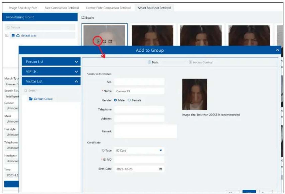
(3) Add a visitor from the real-time smart snapshot interface
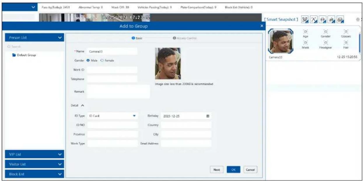
Note: if the operator has no permission of visitor adding, he/she cannot add visitors.
15.3 Search and Export Visitor Record
Set the start and end time and then click [Search] to search the visitor record.
You can also enter the key words and click to search the visitor record.
Click [Export] to export the visitor record to an Excel file. Note that only the super administrator supports visitor record export.

After the access control device is linked to the visitor, the access control device will report the matched information to the platform when the visitor comes.

15.4 Exception Handling
15.4.1 Extending Visit Time or Modify Access Point
There are two ways to handle the exception.
- Go to Visitor Management→Visitor Registration interface as shown below.
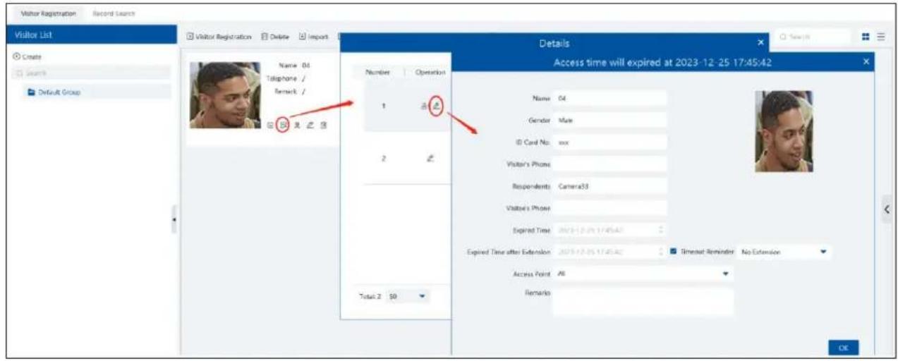

2. Go to Visitor Management→ Record Search
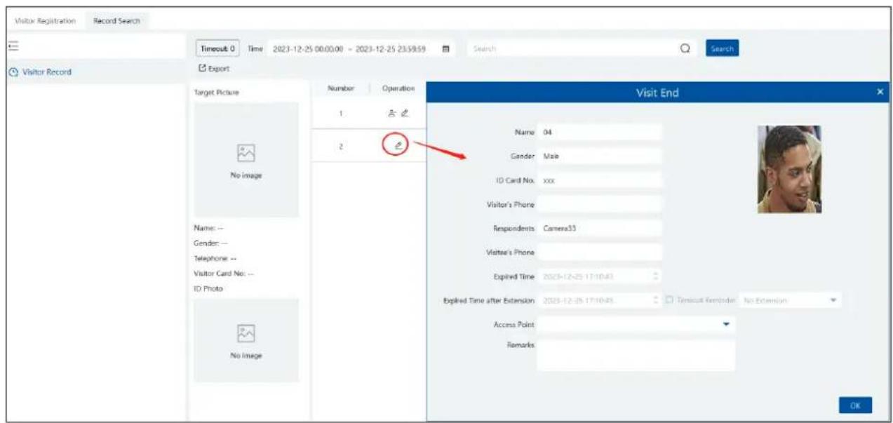
For valid record, you can edit the visit time period and access point.
Please set the expired time or extend the visit time period as needed.
Access Control Permission Group: if the access point or visitor permission group is unbound, the access permission of the corresponding visitors under this access point or visitor permission group will be ineffective.
15.4.2 Not Visiting/Leaving Beyond the Given Time
When someone's visiting is about to exceed the given time or the pre-registered visitor doesn't come within the given time, a prompt
window will appear to remind the operator to extend the visit time or take other actions.
If this prompt window is not handled, the visitor will be marked as "Timeout".
Clicking on the [Timeout] button appears the relevant records
For the timeout record, you can modify the access permission and manually give the permission and extend the expired time.
Click "Finish" to end this record process immediately.
16 Parking Lot Management
Click at the right bottom corner of the home page. Select "Parking Guide" to quickly view the setting steps of the parking lot management.

In the parking guide interface, click the corresponding menus in sequence to quickly set the parking lot.
16.1 Add Devices
- Add LPR Camera
Before using parking lot system, please add LPR cameras first. The LPR camera is use to capture the license plate of the vehicles entering or exiting the parking lot.
There are two ways to add LPR camera.
- Click Home→Resource Management→Add, Edit or Delete Device→Encoding Device to enter the encoding device adding interface. Click [Add] to add your LPR camera.
- Add the LPR camera to your NVR with license plate recognition function and then add this NVR to the platform.
- Add LED Display Screen
Before using parking lot system, please add the LED Display Screen which is used to display the information of the vehicles entering or exiting the parking lot.
Click Home→Resource Management→Add, Edit or Delete Device→LED Display Device to go to the LED display device adding interface.

Port: the default port is 5000.
Type: please select IP screen.
IP address: enter the IP address of the IP screen.
16.2 System Settings
16.2.1 Parking Lot Settings
Go to Parking Lot Management→System Settings→Parking Lot Configuration as shown below.

- Add or Delete Parking Lot
Click + to add a parking lot as shown below.

Select the parking lot and click to delete it. Note that there must be no entrance or exit or vehicle group under the parking lot, or it cannot be deleted.
● Basic Configuration
Select the parking lot and then set the relevant parameters for it. You can modify the parking lot name, set whether to allow temporary vehicle access even if the parking space is full, total parking space, number of the current vehicles (in order to ensure the accuracy counting of remaining parking space, please make sure that no vehicle entering or exiting), remaining parking space, number of overflow vehicles, barrier gate opening duration and repeated license plate waiting time. After that, click [Apply] to save the settings.
Total Parking Space: the set total parking space
Number of the current vehicles: the number of vehicles staying in the parking lot
Remaining parking space: Total parking space minus the number of the current vehicles (if the number of the current vehicles is more than or equal to the total parking space, the reaming parking space will be "0").
Number of overflow vehicles: the number of the current vehicles minus total parking space (if the number of the current vehicles is less than the total parking space, the remaining parking space will be "0").
Repeated license plate waiting time: the same license plate will be identified once within the set waiting time
● Temporary Vehicle Timeout Settings
Overtime Parking of Temporary Vehicles: if enabled, timeout threshold and daily alarm email sending time should be set. Once the temporary vehicles that stay in the parking lot exceed the set timeout threshold, an email will be sent according to the set time.
● Entrance and Exit Settings
Click [Add] next to "Entrance/Exit Setting" to create an entrance/exit. You can directly modify the entrance name and click [Apply] to save the setting.
For the added entrance/exit, click ☑ to delete it. Before deletion, please ensure that there is no lane information under it, or it cannot be deleted.
● License Plate Configuration
You can enter the special characters. When detecting the license plate including the set special characters, the system will automatically release.
- Lane Management
Click [Lane Management] next to the entrance name. This will bring a lane setting window. Click + to add a new lane. Set the lane name, lane type and temporary car release way (manual/auto release). After that, click [Apply] to save the settings.
● Binding LPR Camera
In the lane management window, click [Setup] of the linked LPR camera line to bind the LPR camera as shown below. Multiple cameras can be bound to one lane.

● Binding LED Screen
In the lane management window, click [Setup] of the linked LED screen line to bind the LED screen as shown below. One screen can be bound to one lane only.

● Binding RS485 Screen
In the lane management interface, you can also bind RS485 screen. Enable RS485 screen, select the screen type and then click [Apply]. Before binding RS485 screen, please ensure that the license plate capture camera has been connected to the screen via RS485 interface.

● Binding Vehicle Group
In the lane management window, click "More" to bind vehicle group. Select the vehicle group as needed. Then click [Apply] to save the setting. All vehicles in the vehicle group bound to the lane will be allowed to enter/exit in the parking lot.

Note: A parking lot can add multiple entrances and exits; an entrance/exit can add multiple lanes; a lane can bind multiple license plate capture camera; but one license plate capture camera only can be bound to one lane of the entrance/exit in the parking lot. The name of the parking lot cannot be repeated; the names of entrances/exits in the same parking lot cannot be the same; the names of the lanes in the same entrances/exits cannot be the same.
Other Settings
In the system settings interface, click ✿ at the top right corner to set the LED display and alarm linkage switch.

Alarm linkage: please enable "Block List", "Allow List", "Temporary Car" as needed. If these alarm linkages are enabled, click bottom right corner to view the corresponding alarm information.

at the
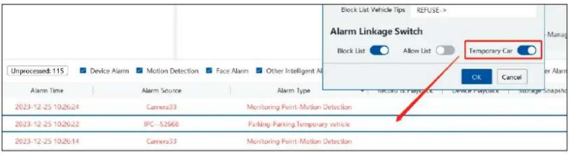
Additionally, only when the above-mentioned alarm linkages are enabled, can the corresponding alarm linkage be set successfully in the alarm center. Go to Home→Alarm Center→Alarm Setting interface, set the alarm type (Parking-Parking, Blacklisted vehicles; Parking-Parking Allow list vehicle; Parking-Parking, Temporary vehicle), select the bound license plate recognition camera (or the bound LPR camera), enable the desired linkage items and set the schedule.
After that, when detecting the corresponding vehicles, the system will trigger alarms accordingly.

16.2.2 Vehicle Group Management
Go to Parking Lot Management→System Settings→Vehicle Group Management interface as shown below.

- Add, Modify or Delete Vehicle Group
Add Vehicle Group:
Move the cursor onto the parking lot name and then "+" will be shown. Click this icon to add a vehicle group. Enter the vehicle group name and then click "More" to set more parameters.

Click

to set the passable area of the vehicle group and admission schedule.

Check "Separate allocation of parking spaces" to separately set total parking spaces and the number of the current vehicles of the vehicle group".
Modify or Delete Vehicle Group:
Move the cursor onto the vehicle group name and then will be shown. Click this icon to delete. If there are vehicles added in the vehicle group, it cannot be deleted. You must delete all vehicle information first and then this vehicle group can be deleted.
Move the cursor onto the vehicle group and then will be shown. Click it to modify the vehicle group name, passable area and admission schedule. After that, click "OK" to save the settings.

Vehicle Information Settings
Add Vehicle Information: Select the vehicle group, click [Add] to add a new vehicle. Fill in the relevant vehicle information. The number plate must be entered.

Delete Vehicle Information:
Select the vehicle information and then click [Delete] to delete the vehicle information.
Note: If the vehicle information you want to delete is bound to other vehicle groups, it will be deleted too in other vehicle groups.
Bulk Binding: in the vehicle group management interface, select the vehicle group and click [Bulk Binding] to bind other vehicles to this vehicle group.
Note: one license plate only can be bound to a vehicle group of other parking lots. It cannot be bound to other vehicle groups of the same parking lot.
File Import: Click[Download Template] to export a. cvs or .xlsx file. Then open the template, edit all vehicle information and then save it.
Click [File Import] and then select the edited file to import all vehicle information.
.cvs template file includes three attributes, including plate number, owner's name, owner's phone.
| A | B | C | D | |
| 1 | (B1) Numbe | (B2) Owner | (B3) Owner's Phone | |
| 2 | A123456 | Simon | 11111111111 | |
| 3 | ||||
| 4 |
.xlsx file includes many attributes, including plate number (compulsory), owner, owner, phone, vehicle color, vehicle type and so on.
| A | B | C | D | E | F | G | H | ||
| 1 | |||||||||
| 2 | Number plate | Owner's Name | Owner's Phone | Description | Vehicle Type | Vehicle Color | Start Time | End Time | |
| 3 | A123456 | Simon | Φ | 11111111111 | Discription | Small Car | Blue | 2022/01/13 | 2022/01/13 |
| 4 | |||||||||
| 5 | |||||||||
Unbind Vehicle: Select the vehicle you want to unbind and then click [Unbind selected]. In the pop-up window, click [OK]. This vehicle will be removed from the current vehicle group. The vehicle information will not be deleted and the binding relationship between the vehicle and other vehicle groups will not changed. This vehicle also can be bound to the other vehicle group of this parking lot. You can also click Unbind to unbind.
Modify Vehicle Information: in the vehicle group management interface, select a vehicle and then click to change this vehicle information.
Vehicle Search: in the search bar, enter the key words to search the vehicle information.
16.2.3 Block List Management
Go to Parking Lot Management → System Settings→Block List Management interface as shown below.

Block list is created by default. Click [Add] to add the vehicle information. The plate number must be entered. The vehicles added to the block list cannot be added to any other vehicle groups.
Select the vehicles and then click [Delete] to delete the vehicles from the block list. Import the vehicles to the block list is the same as vehicle import to other vehicle groups.
Click to modify the vehicle information in the block list. Click [OK] to save the settings.
16.3 Vehicle Monitoring
Click Parking Lot Management→Vehicle Monitoring. Then you can view the real-time lane monitoring video, vehicle passing information, remaining parking space and so on.
16.3.1 Real-time Vehicle Preview
Drag the camera on the left panel to the preview window to view the real time video. 1/2/4/9/16 screen display mode and stream can be selected. Click to close all previews.
![Vehicle Monitoring Integrated Search Beast Statistics System Settings Monitoring Point Mears Parking lot Entrance! Entrance Lane IPC Exit Lane Gate IPC03 2023/11/22 17:04:41 Current Parking Lot Packing lot Remaining Parking S... Total Parking S... 100 100 [ Vehicle Pass Information ] License Plate: Picture: 935 License Plates: IFN03597 Owner's Name: Parking Type: Temporary Car Vehicle Type: Small Car Pass Time: 2023-12-25 10:44:32 Lane: Parking lot_Entrance1_Entrax... Lane Type: Entrance Pass Records: Only display the current preview window records Auto Release Release Not Released Pass Time License Plate Owner's Name Pass Type Parking Type Vehicle Type Parking Lot Entrance Lane Lane Type 2023-12-25 10:44:32 383597 Not Released Temporary Car Small Car Packing lot Entrance1 Entrance La... Entrance 2023-12-25 10:26:22 52668 Not Released Temporary Car Small Car Packing lot Entrance1 Entrance La... Entrance 2023-12-25 10:26:13 83597 Not Released Temporary Car Small Car Packing lot Entrance1 Entrance La... Entrance Term of Validity: Null Temporary car, please release manually Receive Modify Information](/content/2026/05/994503/images/b3c1b7af37f781fd70ffd8405dd6102be0e87a504a7d6bf25237cf21fe8dd303.jpg)
16.3.2 Pass Records
Under the preview window, you can view the real-time vehicle passing records. If "Only display the current preview window records" is checked, the system will only display the vehicle information identified by the camera that is playing in the preview window. If disabled, the vehicle information identified by all cameras under all parking lots will be displayed. You can also filter the passing record by selecting "Auto Release", "Manual Release" or "Not Released".
When the scrollbar on the right of the passing record area is in the top or bottom, the passing record may not refresh; when the scrollbar in the middle, it will stop refreshing and the current passing record page will not change.
16.3.3 Pass Information
On the right panel of the vehicle monitoring interface, it shows vehicle passing information. In the current area, you can view the vehicle image, license plate, lane type, vehicle type, term of validity, enter information and the vehicle status. You can also modify the information of vehicles unreleased (or manually released), including license plate, vehicle type and so on.
Select a preview window and then the passing record area will refresh the vehicle information identified by the camera; Select a passing record, vehicle pass information area will display the selected vehicle information and the passing record will not refresh. Re-select the preview window to continue refreshing.
On the top right of the vehicle monitoring, it is total parking space and remaining parking space display area. Click ☑ to edit the total parking space and remaining parking space. Please make sure there is no vehicle entering or exiting before modification in order to guarantee the accuracy counting of the remaining parking space.
16.4 Integrated Search
16.4.1 Search Pass Information
In this interface, the information of the vehicles entering and exiting the parking lot can be searched.
Set the filtering condition, such as the start and end time, license plate, vehicle type and lane. Click [Search] to search the records.
Click a passing record and then the corresponding license plate image will be displayed on the right. You can zoom in and download it.
At present, up to 3,000,000 passing records can be stored and 120,000 vehicle passing images can be matched to these passing records.
To modify passing record: select a passing record, click [Modify], select the vehicle type and click [OK].
To export the parsing record, search the desired passing record and then click [export] to export the records to the specified file named after "Integrated Search + data" (eg. Integrated Search_20220112_11233555). The export file is .xls file.

16.4.2 Search Overdue Parking
In this interface, you can check the information of the vehicles which stay in the parking lot longer than the predefined parking duration. Before searching, please make sure you have enabled overtime parking of temporary vehicles in the parking lot configuration interface (Click Home→Parking Lot Management→System Settings→Parking Lot Configuration)
16.4.3 Search Vehicles in the Parking Lot
Set the filtering condition (start time, end time, plate number, vehicle type, parking type or parking area), click [Search] to search vehicles in the parking lot. Click [Export] to export the searched vehicle information in the parking lot.

If the searched vehicle has actually been driven away, you can click interface.

to correct. Then the vehicle will not be searched in this
16.5 Report Statistics
Go to Parking Lot Management→Report Statistics interface. In this interface, vehicle flow statistics of all parking lots can be searched and viewed via line chart, bar graph and pie chart.

line
| Time | Traffic Flow Statistics | | ---------- | ------------------------ | | 2021-12-25 | 1.0 |On the left panel, select the parking lot and entrances/exits you want to view the statistical information. Then select the report type and
data. Click to select the desired date; click information.
to select the date range. After that, click [search] to display the statistical
The default granularity is "Entrance". You also can select "Parking Lot" and click [Search] to refresh the vehicle flow data. The report type, time and granularity will be shown on the top of statistical information. The total number of vehicles entering or leaving can be viewed too.
Click w to view the data statistics in the line chart; click ll to view the statistics in the bar graph. You can view the entrance or exit information as needed. Put the cursor on the statistic chart/graph to view the detailed information.

bar
| Time | Parking lot_Entrance1Entrance | Parking lot_Entrance1Exit | Parking lot_GateEntrance | Parking lot_GateExit | |---|---|---|---|---| | 09:00 | 0.8 | 0 | 0 | 0 | | 10:00 | 0 | 0 | 0 | 0 | | 11:00 | 0 | 0 | 0 | 0 | | 12:00 | 0 | 0 | 0 | 0 | | 13:00 | 0 | 0 | 0 | 0 | | 14:00 | 0 | 0 | 0 | 0 | | 15:00 | 0 | 0 | 0 | 0 | | 16:00 | 0 | 0 | 0 | 0 | | 17:00 | 0 | 0 | 0 | 0 | | 18:00 | 0 | 0 | 0 | 0 | | 19:00 | 0 | 0 | 0 | 0 | | 20:00 | 0 | 0 | 0 | 0 | | 21:00 | 0 | 0 | 0 | 0 | | 22:00 | 0 | 0 | 0 | 0 | | 23:00 | 0 | 0 | 0 | 0 | | 24:00 | 0 | 0 | 0 | 0 | | Description | Proportion of Vehicles Entering | |:-------------------------------|----------------------------------| | Parking lot_Gate | ~95% | | Parking lot_ | ~5% | | Parking lot... | ~5% | | No Data | (Not labeled) |Export: You can choose to export Excel or image as needed. Click [Export Excel], select the path and then click "Save" to export the files(.xls). The file name format is "Report Statistics_Date".
Click [Export Picture] to export pictures (.png format).
17 Body Temperature Measurement
17.1 Add Temperature Reading Devices
This platform supports thermal network camera and temperature measurement panel access.
- Click Home→Resource Management→Add, Edit or Delete Device→Encoding Device to go to the encoding device interface. Click [Add] to add the temperature reading devices.
- Click Home→Resource Management→Device Setting to go to the device setting interface. Select the temperature reading device and then click the "Thermal imaging settings" tab to enable temperature measurement function.
- Set the temperature unit, high temperature threshold and low temperature threshold (different devices may have different settings).
- Click [Apply] to save the settings.

17.2 Temperature Screening
17.2.1 Configuration
- Click Home→Temperature Measurement→Live Preview→ to go to the following interface.
- Set the temperature measurement parameters as needed.
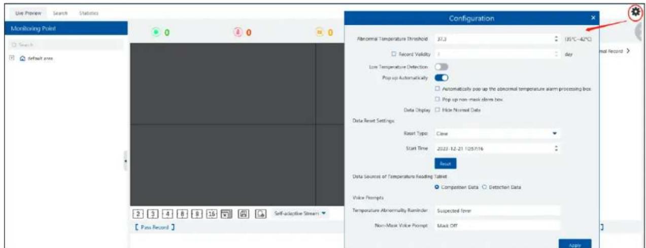
Abnormal temperature threshold: please set the value according to the actual condition. When the temperature detected is over than the set value, alarms will be triggered.
Record validity: Set how long the platform will keep the temperature records. If it is enabled, the temperature records will be cleared beyond the set days.
Pop-up automatically: if enabled, the abnormal temperature alarm processing box will pop up automatically. Additionally, you can enable "Pop up non-mask alarm box" as needed.
Data Display: you can choose "Hide normal data". That is to say, if the temperature of the person scanned is normal and the mask is detected, these data will not be displayed on the client.
Data Reset Settings:
a. Reset time and type: please reset time of the temperature data as needed. These data can be reset every day, every week or every month.
b. You can reset the statistics by clicking [Reset].
Data sources of Temperature Reading Tablet: including comparison data and detection data. If comparison data is selected, the platform will receive the temperature reading result and face comparison result; if detection data is selected, the platform will receive the temperature reading result and face detection result, but it is not sure whether the person is matched with that of the face database
Voice Prompt: Please set the over temp voice prompt and non-mask voice prompt as needed. When no mask or elevated temperature is detected, the set voice prompt will be heard.
17.2.2 Live Preview
Drag the thermal cameras/temperature measurement and face recognition terminals to the preview window. In this interface, you can view various statistical information, such as total pass-by(today/total), over-temperature(today/total), mask off (today/total), etc.

Putting the cursor on the snapshot picture appears a "+" icon. Click this icon to add this picture to the group of the face database.
The thermal image and visible light image will be displayed simultaneously if the thermal camera is dragged to the preview area. Right click on the thermal camera window and then select the fourth stream to view the thermal image.
▶ Alarm Handling
Click the captured image to pop up an alarm handling box as shown below. You can edit the personal information, including name, phone number, ID number, address, whether to go to the infected area, etc.
Click "+" on the top right corner of the snapshot image to add it to the group of the face database.

Pop up automatically: if enabled, the alarm handling box will automatically pop up on detecting an abnormal event (over temp/mask off).
Full Screen Display
In the temperature measurement interface, click

on the top right corner to enter temperature warning system interface.
Click to exit the full screen mode.
17.2.3 Record Search
Select the camera and then set the filter condition (like the start and end time, temperature range, keywords, etc.) to search the records.

In the above interface, you can view the target picture and the original picture, body temperature, mask status, alarm handling status, etc.
17.2.4 Statistics
In the statistics interface, you can view the total pass-through counts, abnormal temperature counts and mask off counts.

line
| Time | Traffic | | -------- | ------- | | 09:00 | 0 | | 81:00 | 0 | | 02:00 | 0 | | 03:00 | 0 | | 04:00 | 0 | | 05:00 | 0 | | 06:00 | 0 | | 07:00 | 0 | | 08:00 | 0 | | 09:00 | 0 | | 10:00 | 0 | | 11:00 | 3 | | 12:00 | 0 | | 13:00 | 0 | | 14:00 | 0 | | 15:00 | 0 | | 16:00 | 0 | | 17:00 | 0 | | 18:00 | 0 | | 19:00 | 0 | | 20:00 | 0 | | 21:00 | 0 | | 22:00 | 0 | | 23:00 | 0 | | 24:00 | 0 |
: Click it to switch between date and date range.
Choose the camera and then set the start time and end time. Click "Search" to view the statistics.
You can view the statistics via a line chart or bar graph. The statistical data can be exported by clicking "Export".
18 Industrial Temperature Measurement
18.1 Thermal Network Camera Settings
Click Home→Resource Management→Add, Edit or Delete Device→Encoding Device to go to the encoding device interface. Click [Add] to add the security thermal network cameras.
18.1.1 Temperature Measurement Settings
After adding the security thermal network camera, click Resource Management→Device Setting→Temperature Measurement Configuration to go to set the temperature measurement parameters.

Color Type: White/Black/Rainbow coding/Red
Restore: Click it to restore the set image to the previous image.
18.1.2 Temperature Alarm Settings
In the device setting interface, select the security thermal network camera and then click the temperature alarm tab as shown below.
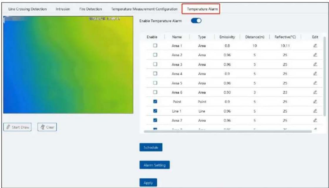
Enable temperature alarm.
Set the rules. Up to 10 rules can be set.
Double click rule name, type, emissivity, distance and reflective temperature of each rule to modify them.
The rule type includes point, line and area.
Edit: set the alarm rule.

After the above alarm rules is set and temperature alarm is enabled, set the alarm linkage items of monitoring point-temperature alarm in the alarm linkage interface. When the detected temperature exceeds the set threshold, the related alarms will be triggered.
Start Draw: select the type and then draw on the image.
Clear: clear the drawn point/line/area.
Schedule: Set the schedule of temperature alarm.
Alarm Setting: Set the alarm of the IPC.
18.1.3 Fire Detection Settings
In the device setting interface, select the security thermal network camera and then click the fire detection tab as shown below.

Schedule: set the schedule of fire detection, 7*24 by default.
Alarm Setting: set the alarm of IPC.
Apply: Click it to save the settings.
Enable: Check it to enable the fire detection function.
18.1.4 Alarm Linkage Settings
Click Alarm Center→Alarm Linkage Settings→Monitoring Point-Fire detection alarm
Enable the alarm linkage items, like record, snapshot, alarm output, etc.
When the detected temperature exceeds the set threshold, alarms will be triggered.

18.2 Temperature Measurement
18.2.1 Video Preview
Go to the video preview interface and then drag the thermal camera to the window to play. The default video stream is the fourth stream (thermal imaging stream). You can switch the stream under the preview window. The temperature measurement rule and the current temperature will be displayed in the image. When the temperature alarm is triggered, they will turn red.

heatmap
| Value | Average (°C) | Highest (°C) | | :--- | :--- | :--- | | Lowest: 26.65° C | 27.55 | 28.05 | | Average: 27.75° C | 28.55 | 28.55 | | Highest: 27.95° C | 28.85 | 28.85 | | Lowest: 26.65° C | 27.75 | 28.55 | | Average: 28.75° C | 28.75 | 28.75 | | Highest: 28.95° C | 28.95 | 28.95 | | Lowest: 26.65° C | 27.75 | 28.65 | The chart displays a color gradient from blue to green to white, representing the magnitude of the measured variable (likely a thermal or environmental parameter). The data is recorded on December 12, 2023, at 08:42:41.18.2.2 Data Analysis
Select the data analysis tab to enter the following interface. Select the temperature measurement rule (multiple rules can be selected) and click [Apply] to view the real-time temperature reading results and image.

line
| Time | Temperature (°C) | |--------|------------------| | 17:04 | 27.35 |Temperature measurement settings: Click ⚙ to open the temperature measurement setting window. You can choose whether to display detection rules and real-time temperature, set sensitivity and temperature rise alarm.

You can set the alarm linkage items of temperature rise alarm. When the rise of the temperature exceeds the set value, the relevant alarms will be triggered. Go to Alarm Center→Alarm Linkage Settings interface and select "Monitoring Point—Abnormal temperature rise" to set the alarm linkage items.
Note: At present, the system will detect the temperature every 10s. If the temperature goes up 0.1^ C every one second, the temperature will rise up 0.5^ C after 5 seconds, but alarms will not be triggered immediately. Alarms will be triggered when the temperature rises up 0.5^ C or higher after 10 seconds.
Different colors stands for different temperature measurement rules. You can view the temperature reading results.
Statistical type: Maximum/average/Minimum temperature.
Show dots: if enabled, the statistical temperature plot will show the dots as shown below. Put the cursor on the dot and then the detailed data will be displayed.
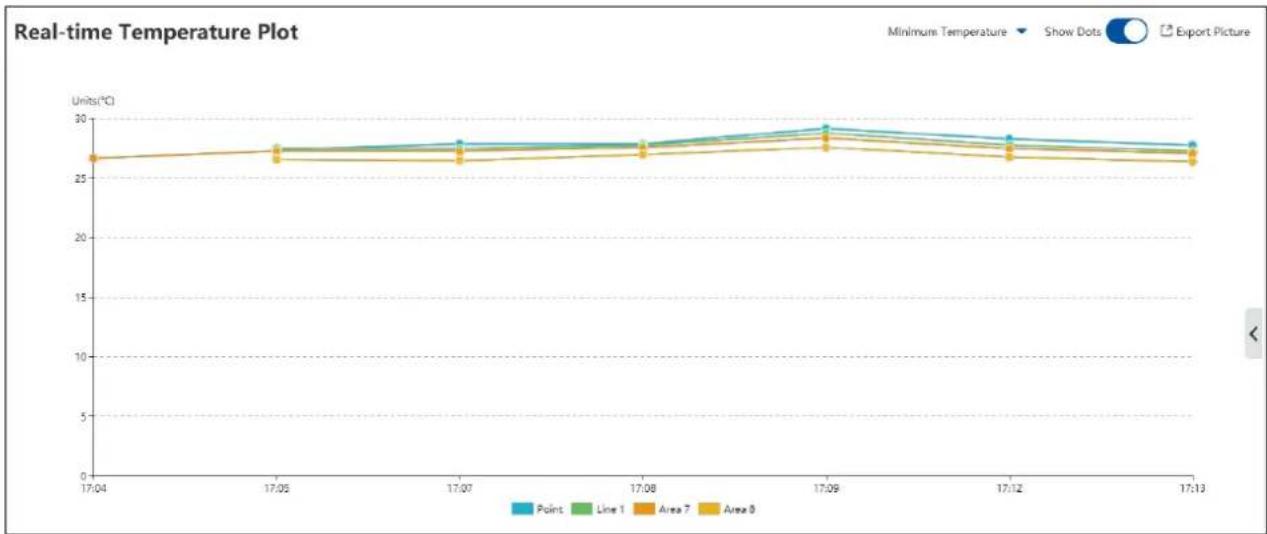
line
| Time | Point | Line 1 | Area 7 | Area 8 | |--------|-------|--------|--------|--------| | 17:04 | 27.0 | 27.0 | 27.0 | 27.0 | | 17:05 | 27.5 | 27.5 | 27.5 | 27.5 | | 17:07 | 28.0 | 28.0 | 28.0 | 28.0 | | 17:08 | 28.5 | 28.5 | 28.5 | 28.5 | | 17:09 | 29.5 | 29.5 | 29.5 | 29.5 | | 17:12 | 28.5 | 28.5 | 28.5 | 28.5 | | 17:13 | 28.0 | 28.0 | 28.0 | 28.0 |: Click it to export the temperature measurement data to the specified file.
Refresh Rules: Click it to refresh the monitoring points and then select the desired rules
Apply: After you select rules, click it to view the line chart.
Real-time Preview: click on the right to extend the video preview window. Select a rule on the left monitoring point panel, this rule will be highlighted. Click any point in the preview window to view the real-time temperature.

heatmap
| Value | Average (°C) | Highest (°C) | | :--- | :--- | :--- | | Lowest: 26.65* C | 27.55* C | 28.05* C | | Average: 27.75* C | 28.55* C | 28.85* C | | Highest: 28.55* C | 27.95* C | 28.55* C | | Lowest: 26.05* C | 27.55* C | 28.05* C | | Average: 28.25* C | 28.25* C | 28.85* C | | Highest: 28.85* C | 27.95* C | 28.55* C | | Lowest: 26.65* C | 27.75* C | 28.75* C | | Average: 28.75* C | 27.95* C | 28.55* C | | Highest: 28.55* C | 27.95* C | 28.05* C | | Lowest: 26.05* C | 27.75* C | 28.05* C | | Average: 28.05* C | 27.95* C | 28.05* C | | Highest: 28.05* C | 27.95* C | 28.05* C | | Lowest: 26.65* C | 27.75* C | 28.75* C | | Average: 28.65* C | 27.95* C | 28.55* C | | Highest: 28.65* C | 27.95* C | 28.05* C | | Lowest: 26.05* C | 27.75* C | 28.05* C | | Average: 28.05* C | 27.95* C | 28.05* C | | Highest: 28.05* C | 27.90* C | 28.05* C | | Lowest: 26.65* C | 27.75* C | 28.75* C | | Average: 27.75* C | 27.95* C | 28.55* C | | Highest: 28.55* C | 27.95* C | 28.05* C | | Lowest: 26.05* C | 27.75* C | 28.05* C | | Average: 28.05* C | 27,95* C | 28,05* C | | Highest: 28,05* C | 27,95* C | 28,05* C | | Lowest: 26,65* C | 27,65* C | 28,05* C | | Average: 26,65* C | 27,95* C | 28,05* C | | Highest: 26,65* C | 27,95* C | 28,05* C | | Lowest: 26,05* C | 27,60* C | 28,05* C | | Average: 26,05* C | 27,90* C | 28,05* C | | Highest: 26,05* C | 27,90* C | 28,05* C | | Lowest: 26,60* C | 27,60* C | 28,05* C | | Average: 26,60* C | 27,90* C | 28,05* C | | Highest: 26,60* C | 27,90* C | 28,05* C | | Lowest: 26,10* C | 27,60* C | 28,05* C | | Average: 26,10* C | 27,90* C | 28,05* C | | Highest: 19,10* C | 27,90* C | 28,05* C | | Lowest: 19,10* C | 27,90* C | 28,05* C | | Average: 19,10* C | 27,90* C | 28,05* C | | Highest: 19,10* C | 27,90* C | 28,05* C | | Lowest: 19,10* D | 27,90* D | 28,05* D | | Average: 19,10D * D | 27,90D * D | 28,05D * D | | Highest: D * D D D D D D D D D D D D D D D D D D D D D D D D D D D D D D D D D D D D D D D D D D D D D D D D D D D D D D D D D D D D D D D D D D D D D D D D D D D D D D D D D D D D D D D D D D D D D D D D D D D D18.2.3 Record Search
Click Industrial Temperature Measurement→Search to go to the following interface. Select one or more rules, set the start and end time and click [Search] to view the temperature data.
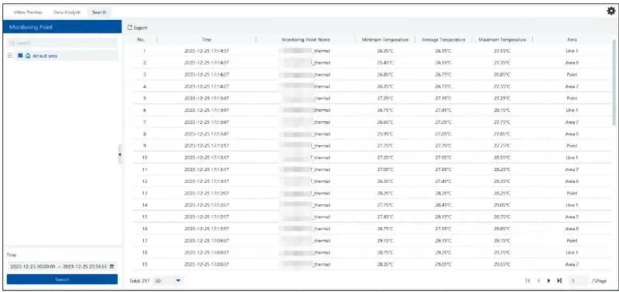
Start/End Time: The end time shouldn't be earlier than the start time.
Export: Click [Export] to export the temperature data to the Excel file as shown below.
| A | B | C | D | E | F | G |
| 6 | 2022-01-13 14:41:59 | Industrial tem | 21.25°C | 21.25°C | 21.25°C | 7 |
| 7 | 2022-01-13 14:41:59 | Industrial tem | 20.85°C | 22.45°C | 24.35°C | 10 |
| 8 | 2022-01-13 14:41:48 | Industrial tem | 33.25°C | 34.55°C | 35.35°C | 10 |
| 9 | 2022-01-13 14:40:28 | Industrial tem | 21.75°C | 21.75°C | 21.75°C | 7 |
| 10 | 2022-01-13 14:39:07 | Industrial tem | 21.25°C | 21.25°C | 21.25°C | 7 |
| 11 | 2022-01-13 14:38:57 | Industrial tem | 23.35°C | 23.35°C | 23.35°C | 5 |
| 12 | 2022-01-13 14:38:16 | Industrial tem | 21.45°C | 21.45°C | 21.45°C | 9 |
| 13 | 2022-01-13 14:37:36 | Industrial tem | 21.95°C | 21.95°C | 21.95°C | 9 |
| 14 | 2022-01-13 14:37:26 | Industrial tem | 21.75°C | 21.75°C | 21.75°C | 7 |
| 15 | 2022-01-13 14:36:05 | Industrial tem | 23.85°C | 23.85°C | 23.85°C | 5 |
| 16 | 2022-01-13 14:34:14 | Industrial tem | 21.85°C | 21.85°C | 21.85°C | 6 |
| 17 | 2022-01-13 14:33:24 | Industrial tem | 20.95°C | 22.55°C | 24.45°C | 10 |
| 18 | 2022-01-13 14:33:14 | Industrial tem | 20.95°C | 22.75°C | 27.75°C | 10 |
| 19 | 2022-01-13 14:32:34 | Industrial tem | 21.35°C | 21.35°C | 21.35°C | 6 |
| 20 | 2022-01-13 14:32:04 | Industrial tem | 21.25°C | 21.25°C | 21.25°C | 7 |
| 21 | 2022-01-13 14:32:04 | Industrial tem | 23.35°C | 23.35°C | 23.35°C | 5 |
| 22 | 2022-01-13 14:28:31 | Industrial tem | 21.45°C | 21.45°C | 21.45°C | 9 |
| 23 | 2022-01-13 14:28:11 | Industrial tem | 21.15°C | 22.15°C | 23.75°C | 2 |
| 24 | 2022-01-13 14:27:30 | Industrial tem | 21.95°C | 21.95°C | 21.95°C | 4 |
| 25 | 2022-01-13 14:27:09 | Industrial tem | 20.85°C | 22.65°C | 24.55°C | 10 |
Delete: if the rule is deleted, all historical temperature measurement records under this rule will be deleted too.
19 User Management
Go to Home→User/Role as shown below.

There is a default super administrator by default. The username is admin; the default password is 1234. The super administrator cannot be deleted.
Modify the password of the super administrator:

If it is the first time for you to log in, please select the super admin user and then click [Edit Security Questions/Answers] to set the questions and answers. It is very important to reset the password if you forget your password.
Select the super administrator and then click [Edit Security Questions/Answers] to modify the questions and answers as needed after verifying the username and password.
Click "Role" to pop up the following interface.

Enter the role name and then check the permission as needed.
Put the cursor on the added role. Two icons will appear. Click to add a user.

After the user is added under the role, put the cursor on the user name. Then a deletion icon will appear. Click it to delete the added user.
20 Operation and Maintenance Management
20.1 Check and Export Log
Go to Home→Operation and Maintenance Management.
Click the "Check and Export Log" tab as shown below. All types of logs can be seared and exported here.
| Check Log Backup and Restore Configuration Real-time Status Status Log | |||||||
| Time 2023-10-18 00:00:00 - 2023-10-18 23:59:59 Log Type All Types Search | |||||||
| Export | |||||||
| No. | Main Type | Record Time | Node Name | Sub Type | User Name | User Address | Details |
| 1 | Operation Log | 2023-10-18 20:28:37 | Client | System Maintenance | admin | Log Search | |
| 2 | Operation Log | 2023-10-18 20:28:21 | Device Name_Camera01 | Preview video | admin | admin 10.15.1.15S C0... | Preview video: Device Name... |
| 3 | Operation Log | 2023-10-18 20:24:49 | Device Name_Camera01 | Preview video | admin | admin 10.15.1.15S C0... | Preview video: Device Name... |
| 4 | Operation Log | 2023-10-18 20:20:03 | Device Name_Camera01 | Preview video | admin | admin 10.15.1.15S C0... | Preview video: Device Name... |
| 5 | Operation Log | 2023-10-18 20:19:55 | Device Name_Camera01 | Preview video | admin | admin 10.15.1.15S C0... | Preview video: Device Name... |
| 6 | Operation Log | 2023-10-18 20:19:39 | Device Name_Camera01 | Preview video | admin | admin 10.15.1.15S C0... | Preview video: Device Name... |
| 7 | Operation Log | 2023-10-18 20:19:25 | Device Name_Camera01 | Preview video | admin | admin 10.15.1.15S C0... | Preview video: Device Name... |
| 8 | Log Configuration | 2023-10-18 20:19:21 | Client | Channel Parameter | admin | ||
Select the log type, set the start time and the end time and then click [Search] to search logs. After the logs are searched, click [Export] to export these logs.
20.2 Backup and Restore Configuration
Go to Home→Operation and Maintenance Management. Click "Backup and Restore Configuration" to go to the following interface.

You can import the former system configuration files to the new version. Click [Backup System Configuration] in the last version to backup the system configuration files. Additionally, TV wall configuration also can be backed up as needed. Then click [Restore System Configuration] in the new version to restore the system configuration.
For TV Wall configuration restoration, you need to go to Home→TV Wall Management→TV Wall System Setting→TV Wall Backup interface and then restore TV Wall configuration by clicking [Restore TV Wall].
20.3 Viewing Online Status
Go to Home→Operation and Maintenance Management→Online Status interface.
You can view the online status of encoding device, decoders and storage servers and the record status of the storage server and encoding
devices.
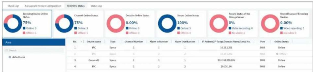
pie
| Feature | Status | Percentage (%) | | :--- | :--- | :--- | | Encoding Device Online Status | Real-time Status | 75 | | Online: 3 | Real-time Status | 0 | | Offline: 1 | Real-time Status | 0 | | Channel Online Status | Disorder Online Status | 0.00 | | Online: 3 | Disorder Online Status | 0 | | Offline: 1 | Disorder Online Status | 0 | | Server Online Status | Record Status of the Storage Server | 100 | | Online: 5 | Record Status of the Storage Server | 100 | | Offline: 0 | Record Status of the Storage Server | 0 | | Video recording: 0 | Record Status of the Storage Server | 0 | | No video: 4 | Record Status of the Storage Server | 0 | | Video recording: 0 | Record Status of the Storage Server | 0 | | No video: 0 | Record Status of the Storage Server | 0 | Area: Device Name Type Channel Number Alarm In Number Alarm Out Number IP Address/IP Range/Domain Name/Serial No. Port Online Status Search default area No. Device Name Type Channel Number Alarm In Number Alarm Out Number IP Address/IP Range/Domain Name/Serial No. Port Online Status 2 IPC Specu 1 2 3 10.15.1.261 9008 Online 3 Camera33 Specu 1 1 1 192.168.250.105 9008 Online 4 IPC Specu 1 2 2 10.15.1.96 9008 Online20.4 Viewing Status Log
Go to Home→Operation and Maintenance Management→Status Log interface.
| Check Log Backup and Restore Configuration Real-time Status Status Log | |||||
| Time 2023-10-18 00:00:00 ~ 2023-10-18 23:59:59 Search Export | |||||
| No. | Type | Record Time | Node Name | Details | |
| 1 | No recording | 2023-10-18 22:27:26 | Device Name_Camera01 | ||
| 2 | Recording | 2023-10-18 22:27:05 | Device Name_Camera01 | ||
| 3 | Recording | 2023-10-18 22:25:57 | Device Name_Camera01 | ||
| 4 | Recording | 2023-10-18 22:25:46 | Device Name_Camera01 | ||
| 5 | Recording | 2023-10-18 22:24:40 | Device Name_Camera01 | ||
| 6 | Recording | 2023-10-18 22:22:50 | Device Name_Camera01 | ||
| 7 | No recording | 2023-10-18 22:04:26 | Device Name_Camera01 | ||
In this interface, record status, online or offline status of servers and monitor client can be viewed.
Set the start time and the end time and then click [Search] to search status logs.
The searched logs can be exported by clicking [Export].
21 Configuration
21.1 Local Configuration
21.1.1 Basic Settings
Go to Home→Configuration→Local Configuration

Auto Login: if enabled the system will automatically log in when running this software next time.
Trigger audio when the node is offline: if enabled, the system will trigger audio when there is node offline.
Show tips when the node is offline: if enabled, the system will pop up tips when there is node offline.
Substream display of new view: if enabled, the new view will be displayed at substream.
Verify the password before exiting the program: if enabled, you shall enter the password before exiting the program.
Server exception Linkage: if enabled, the system will skip to real-time status interface when the server error occurs.
Sound Loop: If enabled, the alarm sound will be repeated continuously.
Temperature Unit: °C or °F can be selected
In this interface, you can also set video configuration rules, language, time display format and so on.
21.1.2 Resource Tree Settings

Full name display for DVR/NVR's channels: if enabled, the DVR/NVR's channel name listed in the resource tree will show the DVR/NVR
name and the channel name. If disabled, only the channel name is shown.
Resource tree automatically expands: please enable as needed.
Show alarm state for the monitoring point: if enabled, the alarm state will be displayed in the monitoring point list as shown below.

In addition, you can also select the resource tree sorting rules as needed.
21.1.3 Record and Snapshot Settings
Go to Home→ Configuration.

In this interface, the playback source, backup file format and max file size for manual recording and record backup can be set up here.
21.1.4 Alarm View Settings
Go to Home→Configuration→Alarm View Setting.
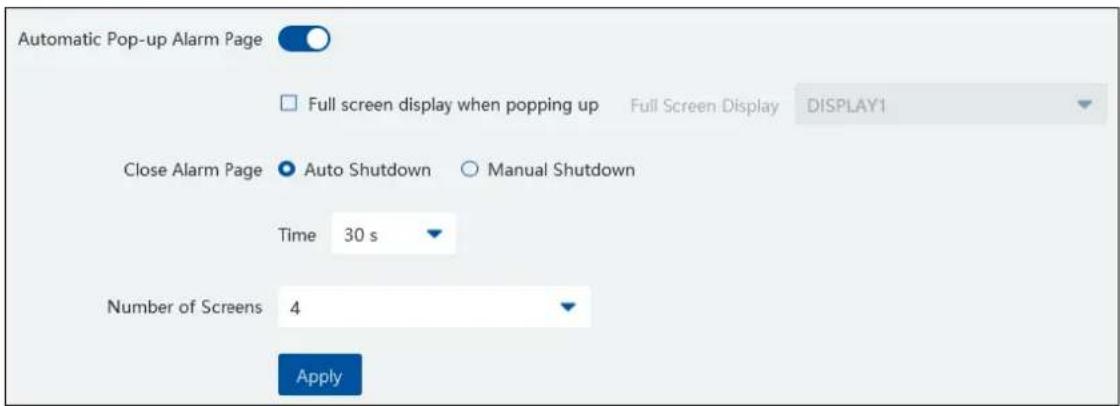
In this interface, users can enable "Automatic Pop-up Alarm Page" or "Full Screen Display when Popping up", set "automatically /manually close alarm page" and select the number of screens (1/4/6/19 optional).
21.1.5 Overload Settings
This system supports CPU and memory overload protection. When the system overloads, the monitor client will restrict the new live view and playback operation and the overload tip will prompt. Go to Home→Configuration→Overload Setting. Select the overload upper limit and then click [Apply] to save the settings.

21.1.6 Snapshot Attribute Display Settings
Go to Home→Configuration→Local Configuration→Snapshot Attribute Display Setting interface as shown below.
The snapshot attribute display and target box display can be set here.
Snapshot attribute display setting: you can set the attributes of face, human and vehicle. Please select the corresponding attributes/features as needed. The attributes of smart snapshot picture will be shown accordingly.

Face attributes/features:
Including gender, age, mask status, temperature, hat, hairstyle, beard, glasses, telephone, skin, a maximum of 6 features can be shown in the smart snapshot area.
Human attributes/features:
Including gender, age, hat, glasses, mask status, glasses, backpack, shoulder bag, upper clothing color, lower clothing color, upper clothing type, lower clothing type, dress/skirt, a maximum of 6 features can be shown in the smart snapshot area.
Vehicle attributes/features:
Including color, type, one or two attributes can be displayed in the smart snapshot area.
Target tracking box:
If enabled, the target tracking box will be shown on the preview/playback window which is playing the video of the IPC enabled the video metadata function.
21.1.7 Network Configuration
Click Home→Configuration→Local Configuration→Network Config to go to the following interface. Set the network parameter according to the actual condition.
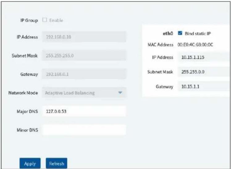
21.1.8 Server Port Configuration
Click Home→Configuration→Server Port Config to go to the following interface.

In this interface, you can set the ports of authentication server, config server, media transfer server, alarm server, TV wall server, intelligent analysis server and so on. The service of all servers is enabled by default. Please set these ports as needed.
21.1.9 System Time Configuration
Click Home→Configuration→System time config to go to the following interface.

Please select the time zone as needed.
You can set the time manually or automatically as needed.
21.1.10 Upgrade System
Click Home→Configuration→Upgrade System to go to the following interface.

Please check "Delete database" or "Delete intelligence server data" as needed.
Insert the USB storage device into the device and then click [Select Upgrade File] to find the upgrade file. Then click [Upgrade System].
During the process of upgrading, please do not power off your device. After the upgrade is finished, the system will automatically reboot.
21.1.11 Other Configuration
Go to Home→Configuration→Other Config.

In this interface, you can enable system SSH service. This service is for test. In addition, you can also disable HTTPS here.
21.2 Server Configuration
21.2.1 System Settings
Click Home→Configuration→Server Configuration→System Setting to go to the following interface.

System Name: Set the platform display name.
Choose "Device Time Correction" and "Synchronize Time Zone" and then click [Synchronize Platform Time] to synchronize the device times with the time of the platform.
Service fault determination time: set the failure duration time. When the server failure exceeds this period of time, it will be determined as "Offline". The spare server will take over.
Log Retention Time: set the log storage time.
Enable License Plate Synchronization: if enabled, you can use the relevant license plate synchronization functions. See the tips shown in the interface for details.
21.2.2 Alarm Settings
Click Home→Configuration→Server Configuration→Alarm Setting to go to the following interface.

In this interface, you can enable "Alarm preview using third stream".
Hide alarms beyond the alarm linkage schedule: Alarms will not be viewed beyond the alarm linkage schedule.
Enable and set the same alarm reporting interval and its linked alarm type. After that, the alarm type will automatically report according to the set interval.
Standard NVR alarm receiving options: please select to receive alarm information or snapshot and alarm information of NVR as needed.
21.2.3 Parking Lot Settings
Set the license language. Default or Arabic can be selected.
21.2.4 Audio Uploading Settings
Go to Home→Configuration→Server Configuration→Audio Uploading Setting.
Click [Add] to bring the following box.
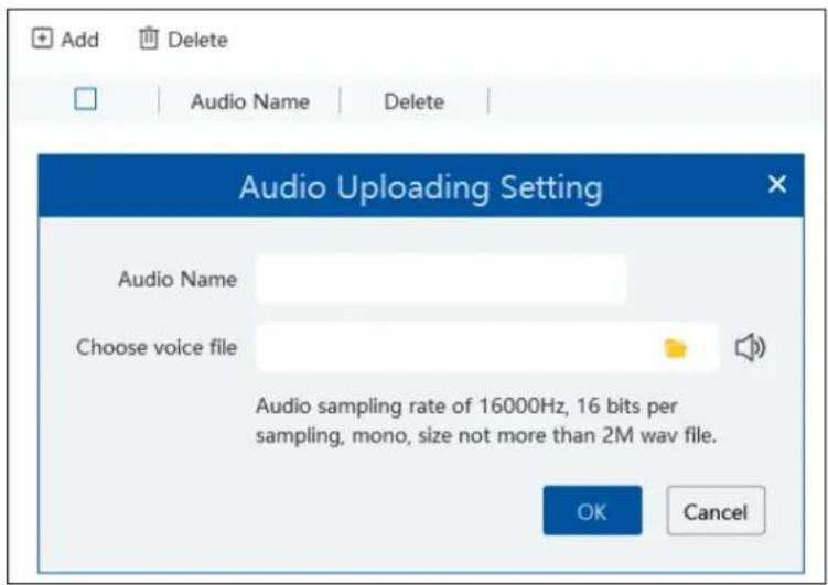
Click

to choose the audio file and then enter the audio name. Click [OK] to save this audio. After the audio is uploaded successfully,
you can listen to it.
22 Data Dashboard
Before opening the data dashboard, please make sure the intelligent server is online.
Go to Home→Resource Management→Intelligent Analysis Server interface. There is a default intelligent server and make sure it is online.
| Add, Edit or Delete Device | Device Setting | Area Setting | Channel Group Setting | Task | |||
| 三 | |||||||
| Encoding Device (Online/Total number: 2/3) | Edit | Server Name | IP Address | Port | Client Connection Status | Authentication Server Connection Status | |
| e | Intelligent Analysis Server | 10.15.1.155 | 6069 | Online | Online | ||
| Decoder (Online/Total number: 1/1) | |||||||
| Intelligent Analysis Server (Online/Total number: ... |
22.1 Create Intelligent Dashboard
Go to Home→Intelligent Dashboard.
Click [Immediately Create] to create the layout of the data dashboard. Drag the module you want to display to the right preview window as needed. After that, click [OK] to save the settings.

Hover the cursor onto the module in the preview window and then you will see a deletion button (✗). Click it to remove the module
from the preview window.
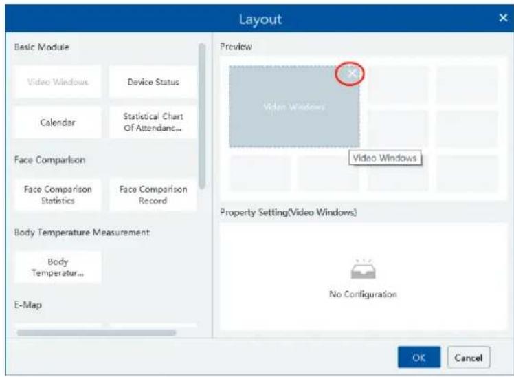
After the data dashboard is created, click

to display it in full screen mode. Click

or ESC to exit the full screen mode. Click

to set the layout of the dashboard.
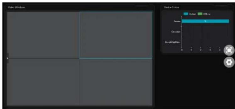
22.2 Basic Module
Video window supports 4-screen display mode. Click to extend the monitoring points. Drag the camera to the preview window or double click the camera to play the video. You can drag the playing window to other windows.
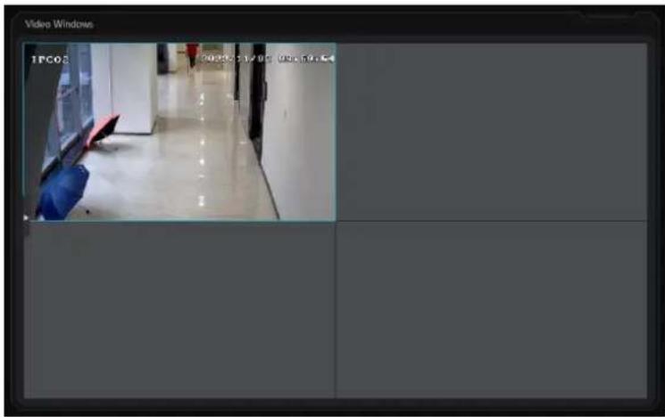
Other modules can set its attributes that you want to display as needed.

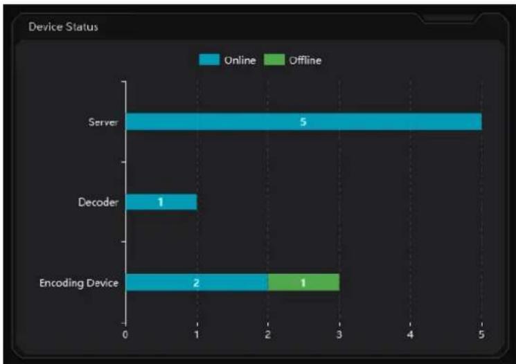
bar
| Device Status | Online | Offline | |---|---|---| | Server | 5 | 0 | | Decoder | 1 | 0 | | Encoding Device | 2 | 1 |22.3 Face Comparison Display
Face Comparison display includes face comparison statistics and face comparison record display. In the layout interface, drag these two modules to the preview window. Then you can set the attributes as needed.


bar
Face Comparison Statistics | Category | Value | |---|---| | Passes... | 1105 | | Abnormal... | 0 | | Without... | 0 | | Face ... | 1105 | | Block... | 0 | | Strang... | 1105 |Smart Snapshot module: You can set the snapshot channel and attributes.
In the face comparison records, you can view the comparison similarity. Click to quickly skip to face comparison retrieval interface.
Click ☐ to pop up the detail box. In this box, you can modify the personnel information; click + to add this person to the face database.

22.4 Body Temperature Measurement Display
In the layout interface, select the body temperature module and then set the attributes you want to display as shown below.

The body temperature measurement of the intelligent dashboard is shown as below.

bar
Body Temperature Measurement | Category | Value | |---|---| | Passe... | 11 | | Suspe... | 11 | | Witho... | 11 |22.5 E-map Display
E-Map includes E-map monitoring and heat map analysis. The layout settings are as follows.

You need to set the hotspots in advance and then you can view here. Please refer to E-Map→E-Map Monitoring for details.

Heat map module: The more people/vehicles enter, the deeper the color is. Move the cursor on the monitoring point to view the current traffic flow. You need to set the E-map and hotspots in advance. Please refer to E-map settings chapter for details.
Besides the above hotspot setting, you can set other parameters as shown below.

In the heat map module of the intelligent dashboard, you can view the statistics of human/motor-vehicle/non-motor vehicle.
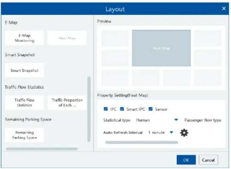
22.6 Smart Snapshot Display
You need to set the snapshot attributes in the layout interface and then the relevant data can be viewed on the dashboard. The smart snapshot type includes face, license plate, human body, motor vehicle and non-motor vehicle. Please select them as needed.
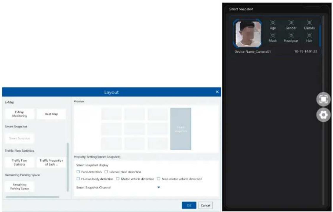
22.7 Traffic Flow Statistics Display
You need to set the statistical type, auto refreshing interval and channel in advance. Please refer to Target Counting → Task Management for details. Then set the layout of traffic statistics and display attributes.
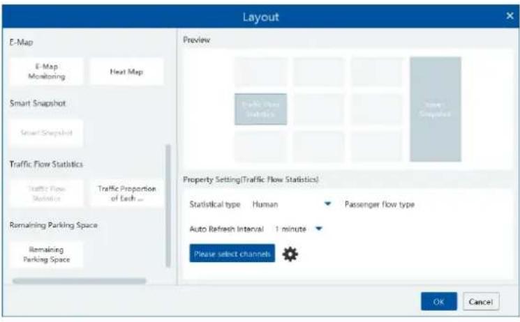
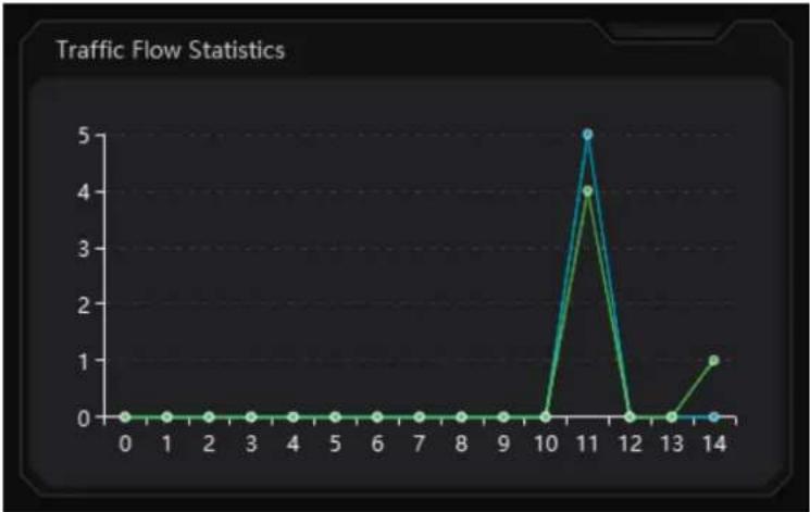
line
Traffic Flow Statistics | Time Point | Traffic Flow | | :--- | :--- | | 0 | 0 | | 1 | 0 | | 2 | 0 | | 3 | 0 | | 4 | 0 | | 5 | 0 | | 6 | 0 | | 7 | 0 | | 8 | 0 | | 9 | 0 | | 10 | 0 | | 11 | 5 | | 12 | 0 | | 13 | 0 | | 14 | 1 |22.8 Remaining Parking Space Display
Select the parking lot in the property area and then you can view the remaining parking lot here.

pie
Remaining Parking Space | Category | Value | |---|---| | Parking lot_Use... | 0 | | Parking lot_Rem... | 100 |23 Troubleshooting
1. How to modify the password by yourself?
Login monitor client and then go to the User Management interface. Select the user to modify the password. Then click [Save].

2. The device information cannot be seen or the device is offline after the user logins.
1) Please check whether this user account is an administrator account. If this account is an operator account, please check whether it has the authority to view the device information.
2) Please check whether the media transfer server of the device has been started.
3. The alarm information cannot be received after the user logins.
1) Please check whether the schedule of sensor alarm, motion detection alarm and so on are set in the SPECO BLUE VMS system.
2) As for remote login device in the monitor client, please check whether alarms and alarm schedules of the remote login device have enabled.
4. The record cannot playback after the user logins.
1) Please check whether the storage server is online. If it is online, please check whether this account logged on has playback permission.
2) Please check whether the record source selected has record data. If you want to get record data from a storage server, please check whether to set the record schedule of the storage server or not.
3) Checkwhether there are record data in the playback channel and whether the record source and the start time and the end time of the playback is set up correctly.
4) Please check the record schedules of the storage server are set correctly.
5. The configuration of devices cannot be modified remotely after the user logins.
1) When the device configuration is required by the monitor client and prompts "Someone is configuring. Please try later", please open the IE browser to login to the device remotely and then go to "Online user" interface to see if there are any other users logging in.
2) Please go to the live to see whether the device is being set up.
3) If the problem still exists, please contact your device manufacturer.
Notes
- Please use super administrator or standard user (permission control is set to "Never Notify") to log in operation system, install and use servers and client software.
- The resolution of the surveillance client's monitor shall be more than 1280*960.
- If you want to delete the files of a server, please stop the server first.
Model: SB01M
Federal Communications Commission (FCC) Statements
This device complies with Part 15 of the FCC Rules. Operation is subject to the following two conditions: (1) This device may not cause harmful interference, and (2) This device must accept any interference received, including interference that may cause undesired operation.
FCC Responsible Party:
Speco Technologies
200 New Highway
Amityville, NY 11701
www.specotech.com

- SpecoBlue VMS Enterprise
- User Manual
- Notes
- Contents
- Face Greeting....30
- Face Attendance....33
- Face Access Control....44
- Video Preview....47
- Record & Playback 61
- Alarm Management....71
- E-Map 78
- TV Wall 80
- Target Counting....93
- Visitor Management 98
- Parking Lot Management 104
- Body Temperature Measurement....115
- Industrial Temperature Measurement....119
- Thermal Network Camera Settings....119
- Temperature Measurement....121
- User Management 125
- Operation and Maintenance Management....127
- Configuration....129
- Local Configuration....129
- Server Configuration....133
- Data Dashboard 135
- Troubleshooting....143
- Introduction
- Welcome
- Front & Rear Panel Instructions
- Login
- Login
- Quick Wizard Settings
- Main Menu Interface Introduction
- Device Management
- Add Encoding Device
- Quickly Add
- Note:
- Manually Add
- Auto Report
- Quickly Add Auto Report Device
- Modify or Delete Device
- Device Area Selection
- Batch Import/Export
- Device Upgrade
- Device Setting
- Area Setting
- Server Settings
- - Add Storage Server
- Channel Group Settings
- Task Management
- Group Management
- People Management
- Add Group
- - Add the parent group
- - Add the sub group:
- Add Target
- - Add target one by one
- - Batch Import
- ➢ Convert images to an Excel
- #
- Vehicle Management
- Add Vehicles
- View, Modify or Delete Vehicles
- Import or Export Vehicles
- Permission Management
- ➢ Add Permission Group
- ● Weekly Schedule:
- - Holiday Schedule
- ▶ Permission Binding
- People Sync Record Query
- ➢ Vehicle Sync Record Query
- Search
- Image Search by Face
- Face Comparison Search
- License Plate Comparison Search
- Smart Snapshot Search
- Face Greeting
- Face Attendance
- Add Devices and Targets
- Add Devices
- Add Targets
- ▶ Permission Management
- Attendance Configuration
- Attendance Check Point Settings
- Attendance Period Settings
- ▶ Regular Attendance
- Time Setup:
- Flextime:
- ▶ Flexible Attendance
- Attendance Shift Settings
- Personnel Scheduling
- Attendance Handling
- Cancel Leave/Business-Trip:
- Correct Check-in/out Time:
- Holiday Settings
- Basic Configuration
- Search Attendance Record
- Statistics by day/month
- ➢ Attendance Record
- Export Reports
- ▶ Send Reports Regularly
- Statistics of Attendance Data
- Real-time Monitoring
- Real-time Monitoring
- Data Synchronization
- Face Access Control
- Add Face Recognition & Access Control Device
- Permission Settings
- Event Linkage
- Record Search
- Pass Record
- Incoming Call record
- Two-Way Talk
- Real-Time Monitoring
- E-Map Access Control
- Video Preview
- Video Preview
- Monitoring Point View
- - Start View
- - Stop View
- Channel Group View
- Channel Group Setting
- Start Channel Group View
- ➢ Stop Channel Group View
- Smart View
- Face Comparison
- Add face comparison device→Create a group → Add targets to the group → Set task → Real-time View → Search faces
- ● View the real-time snapshot and comparison result
- ● Face Comparison Display Settings
- License Plate Comparison
- ● License Plate Capture and Comparison Settings
- ● License Plate Capture Records
- ● License Plate Comparison Records
- Plan View
- - Add View Plan:
- - Modify or Delete View Plan
- - Start/stop auto-switch
- PTZ Control
- Record & Playback
- Record Configuration
- Schedule Recording
- Alarm Linkage Recording
- Playback
- Normal Playback
- Smart Playback by Face
- Smart Playback by License Plate
- Playback by Time
- Playback by Event
- Playback by Tag
- Record Backup
- Search Picture
- Alarm Management
- Alarm Server Configuration
- Alarm Configuration
- SOP Settings
- Alarm Task Settings
- Email Setting
- Alarm View
- Alarm Log
- Manual Alarm Out
- E-Map
- E-Map Settings
- Create E-Map
- Add Hotspot
- E-Map Monitoring
- TV Wall
- Add Device
- Add Decoder
- Create and Connect Decoder
- TV Wall Management
- TV Wall System Settings
- Channel Number Settings
- Decoder Setting
- TV Wall Alarm Linkage Settings
- Video Preview
- Execute auto-switch
- Modify or delete auto-switch
- Create auto-switch plan
- Start/stop auto-switch
- Modify auto-switch plan
- Decoder Input
- Playback
- ◆ Playback on TV Wall
- ◆ Playing control
- TV Wall Task Setting
- TV Wall Backup
- Target Counting
- Task Management
- Real-time Statistics
- Heat Map
- Historical Statistics
- Flow Control
- Visitor Management
- Add Access Control Devices
- Apply for a Visit
- Search and Export Visitor Record
- Exception Handling
- Extending Visit Time or Modify Access Point
- Go to Visitor Management→ Record Search
- Not Visiting/Leaving Beyond the Given Time
- Parking Lot Management
- Add Devices
- - Add LPR Camera
- - Add LED Display Screen
- System Settings
- Parking Lot Settings
- - Add or Delete Parking Lot
- ● Basic Configuration
- ● Temporary Vehicle Timeout Settings
- ● Entrance and Exit Settings
- ● License Plate Configuration
- - Lane Management
- ● Binding LPR Camera
- ● Binding LED Screen
- ● Binding RS485 Screen
- ● Binding Vehicle Group
- Other Settings
- Vehicle Group Management
- - Add, Modify or Delete Vehicle Group
- Add Vehicle Group:
- Modify or Delete Vehicle Group:
- Vehicle Information Settings
- Delete Vehicle Information:
- Block List Management
- Vehicle Monitoring
- Real-time Vehicle Preview
- Pass Records
- Pass Information
- Integrated Search
- Search Pass Information
- Search Overdue Parking
- Search Vehicles in the Parking Lot
- Report Statistics
- Body Temperature Measurement
- Add Temperature Reading Devices
- Temperature Screening
- Configuration
- Data Reset Settings:
- Live Preview
- ▶ Alarm Handling
- Full Screen Display
- Record Search
- Statistics
- Industrial Temperature Measurement
- Thermal Network Camera Settings
- Temperature Measurement Settings
- Temperature Alarm Settings
- Fire Detection Settings
- Alarm Linkage Settings
- Temperature Measurement
- Video Preview
- Data Analysis
- Record Search
- User Management
- Operation and Maintenance Management
- Check and Export Log
- Backup and Restore Configuration
- Viewing Online Status
- Viewing Status Log
- Configuration
- Local Configuration
- Basic Settings
- Resource Tree Settings
- Record and Snapshot Settings
- Alarm View Settings
- Overload Settings
- Snapshot Attribute Display Settings
- Network Configuration
- Server Port Configuration
- System Time Configuration
- Upgrade System
- Other Configuration
- Server Configuration
- System Settings
- Alarm Settings
- Parking Lot Settings
- Audio Uploading Settings
- Data Dashboard
- Create Intelligent Dashboard
- Basic Module
- Face Comparison Display
- Body Temperature Measurement Display
- E-map Display
- Smart Snapshot Display
- Traffic Flow Statistics Display
- Remaining Parking Space Display
- Troubleshooting
- How to modify the password by yourself?
- The device information cannot be seen or the device is offline after the user logins.
- The alarm information cannot be received after the user logins.
- The record cannot playback after the user logins.
- The configuration of devices cannot be modified remotely after the user logins.
- Model: SB01M
- Federal Communications Commission (FCC) Statements
- FCC Responsible Party:
Brand : Speco Technologies
Model : SB01M
Category : Digital Video Recorder