
BS-1120W - Loudspeaker TOA - Free user manual and instructions
Find the device manual for free BS-1120W TOA in PDF.


| Product Type | Speaker |
| Model | BS-1120W |
| Brand | TOA |
| Rated Input | 20 W |
| Rated Impedance | 100 V line: 500 Ω (20 W), 1 kΩ (10 W); 70 V line: 250 Ω (20 W), 500 Ω (10 W); 8 Ω (20 W) |
| Sound Pressure Level | 93 dB (1 W, 1 m) |
| Frequency Response | 150 – 20,000 Hz |
| Speaker Component | 12 cm cone-type x 4 + balanced dome-type x 1 |
| Applicable Cable | 600 V vinyl-insulated cable (IV wire or HIV wire); Solid copper wire: ø0.8 - ø1.2 mm; 7-core twisted copper wire: 0.75 - 1.25 mm² |
| Connection | Push-in connector (Bridging connections possible) |
| Operating Temperature | -10°C to +50°C |
| Dimensions (W x H x D) | 180 x 720 x 100 mm |
| Weight | 5.1 kg (unit only) |
| Enclosure Finish | Plywood vinyl coating, white |
| Front Finish | ABS resin, white, paint |
| Rear Finish | Steel plate, white, paint |
| Bracket Finish | Steel plate, white, paint |
| Mounting Options | Wall mounting directly or with supplied bracket; optional ST-16 stand (BS-1110W only); optional YS-301 bracket |
| Impedance Switching | Rear-mounted slide switch for high (70/100 V) or low (8 Ω) impedance |
| Accessories Included | Bracket x 2 |
| Safety Features | Safety wire attachment point; warning against vibration, overloading, and improper mounting |
Frequently Asked Questions - BS-1120W TOA
User questions about BS-1120W TOA
0 question about this device. Answer the ones you know or ask your own.
Ask a new question about this device
Download the instructions for your Loudspeaker in PDF format for free! Find your manual BS-1120W - TOA and take your electronic device back in hand. On this page are published all the documents necessary for the use of your device. BS-1120W by TOA.
USER MANUAL BS-1120W TOA
Please follow the instructions in this manual to obtain the optimum results from this speaker.
We also recommend that you keep this manual handy for future reference.
The BS-1110W and BS-1120W Speakers feature the wide-band and high-quality design which makes them ideal for such applications as announcements and music reproduction.
1. SAFETY PRECAUTIONS
- Be sure to read the instructions in this section carefully before use.
- Make sure to observe the instructions in this manual as the conventions of safety symbols and messages regarded as very important precautions are included.
- We also recommend you keep this instruction manual handy for future reference.

WARNING Indicates a potentially
hazardous situation which, if mishandled, could result in death or serious personal injury.
- Use only the specified amplifier output voltage and impedance, as exceeding the specified limits could result in fire or other failures (high-impedance applications).
- To avoid accidental air explosions, do not use the unit around gasoline, thinner or other combustibles.
- Install the unit only in a location that can structurally support the weight of the unit and the mounting bracket. Doing otherwise may result in the unit falling down and causing personal injury and/or property damage.
- Do not use other methods than specified to mount the bracket. Extreme force is applied to the unit and the unit could fall off, possibly resulting in personal injuries.
- Use nuts and bolts that are appropriate for the ceiling's or wall's structure and composition. Failure to do so may cause the speaker to fall, resulting in material damage and possible personal injury.
- Tighten each nut and bolt securely. Ensure that the bracket has no loose joints after installation to prevent accidents that could result in personal injury.
- Attach the safety wire to the unit when mounting in locations high above the ground. Failure to do so could result in personal injury if the speaker should later fall for any reason.

WARNING Indicates a potentially
hazardous situation which, if mishandled, could result in death or serious personal injury.
- Avoid mounting the unit in locations exposed to constant vibration. The mounting bracket can be damaged by excessive vibration, potentially causing the speaker to fall, which could result in personal injury.

CAUTION Indicates a potentially hazardous
situation which, if mishandled, could result in moderate or minor personal injury, and/or property damage.
- To avoid electric shocks, be sure to switch off the amplifier power when connecting the speaker.
- Avoid installing the unit in humid or dusty locations, or in locations exposed to heaters, solvents, acid, alkali, smoke, or steam, as excessive exposure to these factors could result in the speaker falling off, electric shock or fire.
- Do not operate the unit for an extended period of time with the sound distorting. This is an indication of a malfunction, which in turn can cause heat to generate and result in a fire.
- Do not stand or sit on, nor hang down from the unit as this may cause it to fall down or drop, resulting in personal injury and/or property damage.
- Have the unit periodically checked by the shop from where it was purchased. Failure to do so could result in the speaker falling off due to damage or corrosion to the speaker or its mounts, and possible personal injury.
2. FEATURES
- A built-in matching transformer permits the speaker to be used for both high-impedance and low-impedance (BS-1110W: 4 Ω, BS-1120W: 8 Ω) applications. The impedance can be easily changed from outside the speaker.
- Mountable to wall surfaces directly or using with supplied or optional mounting brackets.
3. INPUT IMPEDANCE CHANGE
The speaker's impedance is factory-preset as follows.
BS-1110W: 100 V line, 10 W (1k Ω) input
BS-1120W: 100 V line, 20 W (500 Ω) input
To change the impedance, use the rear-mounted slide switch.
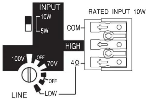
3.1. High Impedance (70 V or 100 V Line) Applications
Set the LINE switch to 70 V or 100V, and also the INPUT switch to 10 W or 5 W you use. (The example below shows the setting for 10 W on the 100 V line of the BS-1110W.) In this case, use the speaker terminals HIGH and COM for connection to an amplifier.
3.2. Low Impedance Applications
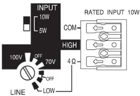
Set the LINE switch to the LOW position. (Shown below is a setting example of the BS-1110W.)
In this case, use the speaker terminals 4 Ω and COM for connection to an amplifier.
Notes
To avoid damage to the speaker, be sure to follow the instructions below.
- Switch off the amplifier power when changing the input.
- Never connect the speaker to the amplifier's 70 V or 100 V line (high impedance) when setting the LINE switch to the LOW position (4 Ω or 8 Ω).
4. SPEAKER INSTALLATION
4.1. Wall Mounting – With Surface-Mount Screws
Note: The surface-mount screws are not supplied with the unit. Referring to the mounting hole's dimensional diagram below, prepare the screws appropriate to the wall material.
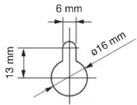
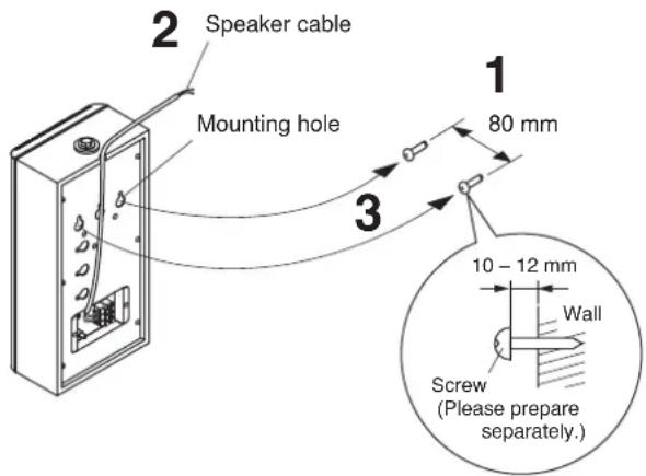
Step 1. Install 2 surface-mount screws in the wall 80 mm apart and leave them sticking out approximately 10 – 12 mm from the wall surface.
Step 2. Connect the speaker cable.
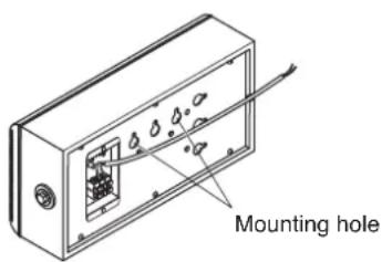
Step 3. Place the speaker's rear panel mounting holes over the 2 installed screws to mount the speaker to the wall surface.
Note
Route the speaker cable as shown in the figure so that it is not pinched between the speaker and the wall surface.
[When installing the BS-1110W horizontally]
Use the relevant mounting holes shown below. (BS-1110W only)
Note
As for the BS-1120W, never use the mounting holes for its horizontal installation.
4.2. Wall Mounting – With Supplied Bracket
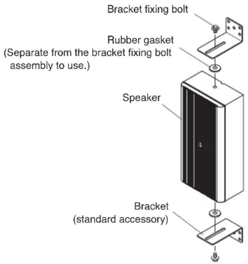
Step 1. Attach the bracket to the speaker using the supplied bracket fixing bolt*.
* Pre-mounted to the speaker at the factory. Remove it to use.
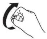
The logo mark can be changed to correct its orientation.
Step 2. Mount the speaker in the desired location using the mounting holes made in the bracket.
Note
Bracket mounting hardware is not supplied with the unit. Referring to the bracket's dimensional diagram, prepare the screws or bolts appropriate to the wall material.
4.3. Mounting on the Optional ST-16 Speaker Stand (applicable to the BS-1110W only)
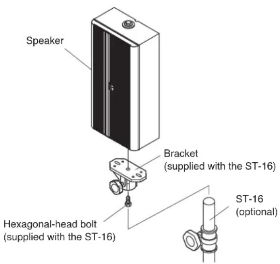
Remove the pre-mounted bracket fixing bolt from the bottom of the speaker, then mount the speaker stand as illustrated below.
4.4. Mounting with Other Brackets
The following table shows the brackets that can be used for the speakers. When using these brackets, refer to their corresponding instruction manuals.
| Usable Brackets | BS-1110W | BS-1120W |
| Speaker Mounting Bracket YS-301 | OK | OK |
| Speaker Mounting Bracket SP-410 | OK | — |
| Wall/Ceiling Mounting Bracket WCB-12W | OK | — |
| Table Mounting Bracket TMB-1W | OK | — |
5. DIMENSIONAL DIAGRAM
• BS-1110W
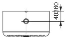
Unit: mm
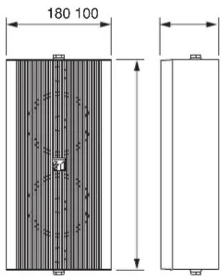
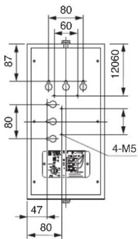
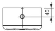
Unit: mm
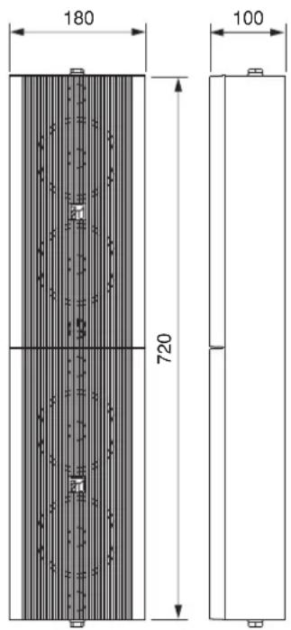
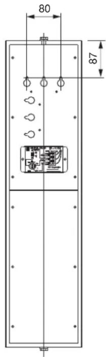
(standard accessory, common to BS-1110W/-1120W)
- Bracket
Unit: mm
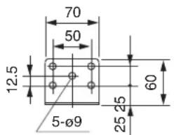
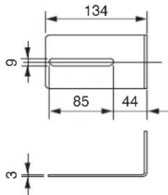
6. SPECIFICATIONS
• BS-1110W
| Rated Input | 10 W |
| Rated Impedance | 100 V line: 1 kΩ (10 W), 2 kΩ (5 W)70 V line: 500 Ω (10 W), 1 kΩ (5 W)4 Ω (10 W) |
| Sound Pressure Level | 90 dB (1 W, 1 m) |
| Frequency Response | 150 – 14,000 Hz |
| Speaker Component | 12 cm cone-type x 2 |
| Applicable Cable | 600 V vinyl-insulated cable (IV wire or HIV wire)Solid copper wire: ø0.8 - ø1.2 mm7-core twisted copper wire: 0.75 - 1.25 mm^2 |
| Connection | Push-in connector (Bridging connections possible) |
| Operating Temperature | - 10°C to +50°C |
| Dimensions | 180 (w) x 360 (h) x 100 (d) mm |
| Finish | Enclosure: Plywood vinyl coating, whiteFront: ABS resin, white, paintRear: Steel plate, white, paintBracket: Steel plate, white, paint |
| Weight | 2.9 kg (unit only) |
Note: The design and specifications are subject to change without notice for improvement.
- BS-1120W
| Rated Input | 20 W |
| Rated Impedance | 100 V line: 500 Ω (20 W), 1 kΩ (10 W)70 V line: 250 Ω (20 W), 500 Ω (10 W)8 Ω (20 W) |
| Sound Pressure Level | 93 dB (1 W, 1 m) |
| Frequency Response | 150 – 20,000 Hz |
| Speaker Component | 12 cm cone-type x 4+ balanced dome-type x 1 |
| Applicable Cable | 600 V vinyl-insulated cable (IV wire or HIV wire)Solid copper wire: ø0.8 - ø1.2 mm7-core twisted copper wire: 0.75 - 1.25 mm ^2 |
| Connection | Push-in connector (Bridging connections possible) |
| Operating Temperature | - 10°C to +50°C |
| Dimensions | 180 (w) x 720 (h) x 100 (d) mm |
| Finish | Enclosure: Plywood vinyl coating, whiteFront: ABS resin, white, paintRear: Steel plate, white, paintBracket: Steel plate, white, paint |
| Weight | 5.1 kg (unit only) |
Note: The design and specifications are subject to change without notice for improvement.
• Accessories (BS-1110W/-1120W)
Bracket 2
Traceability Information for Europe
Manufacturer:
TOA Corporation
7-2-1, Minatojima-Nakamachi, Chuo-ku, Kobe, Hyogo, Japan
Authorized representative:
TOA Electronics Europe GmbH
Suederstrasse 282, 20537 Hamburg, Germany
- SAFETY PRECAUTIONS
- WARNING Indicates a potentially
- CAUTION Indicates a potentially hazardous
- FEATURES
- INPUT IMPEDANCE CHANGE
- High Impedance (70 V or 100 V Line) Applications
- Low Impedance Applications
- Notes
- SPEAKER INSTALLATION
- Wall Mounting – With Surface-Mount Screws
- Note
- [When installing the BS-1110W horizontally]
- Wall Mounting – With Supplied Bracket
- Mounting on the Optional ST-16 Speaker Stand (applicable to the BS-1110W only)
- Mounting with Other Brackets
- DIMENSIONAL DIAGRAM
- SPECIFICATIONS
- • Accessories (BS-1110W/-1120W)
Brand : TOA
Model : BS-1120W
Category : Loudspeaker