MX-AC-TMPLT-MXR10 - Cutting machine AMX - Free user manual and instructions
Find the device manual for free MX-AC-TMPLT-MXR10 AMX in PDF.


| Product Type | Cutting machine |
| Brand | AMX |
| Model | MX-AC-TMPLT-MXR10 |
| Dimensions (W x D x H) | 400 x 300 x 200 mm |
| Weight | 5.5 kg |
| Power Supply | 220-240 V AC, 50/60 Hz |
| Power Consumption | 150 W |
| Cutting Width | 300 mm |
| Cutting Depth (max) | 5 mm |
| Cutting Speed | Adjustable, 0-10 m/min |
| Blade Type | Rotary blade |
| Supported Materials | Paper, cardboard, vinyl, thin plastic |
| Safety Features | Blade guard, automatic shut-off, emergency stop button |
| Maintenance | Clean blade after each use, lubricate moving parts monthly |
| Replacement Parts Availability | Blades and drive belts available separately |
| Repairability Index | 7/10 (easy access to main components) |
| Included Accessories | Blade set, cutting mat, user manual |
| Noise Level | ≤ 70 dB(A) |
| Certifications | CE, RoHS |
| Warranty | 2 years |
Frequently Asked Questions - MX-AC-TMPLT-MXR10 AMX
User questions about MX-AC-TMPLT-MXR10 AMX
0 question about this device. Answer the ones you know or ask your own.
Ask a new question about this device
Download the instructions for your Cutting machine in PDF format for free! Find your manual MX-AC-TMPLT-MXR10 - AMX and take your electronic device back in hand. On this page are published all the documents necessary for the use of your device. MX-AC-TMPLT-MXR10 by AMX.
USER MANUAL MX-AC-TMPLT-MXR10 AMX
The MX-AC-TMPLT-MXR10 HydraPort® Installation Router Guide for MXR-1001 (FG5968-90) provides an easy and accurate method of creating a hole in the installation surface for the MXR-1001 10.1" Modero X® Series G5 Retractable Touch Panel (FIG. 1):
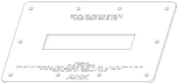
FIG. 1 MX-AC-TMPLT-MXR10 ROUTER GUIDE
Use the MX-AC-TMPLT-MXR10 along with the required accessories to create the hole in the mounting surface to install the MXR-1001.
MX-AC-TMPLT-MXR10 SPECIFICATIONS
| Dimensions: | |
| Outside Dimensions: | Horizontal: 18.897" (480.0 mm)Vertical: 11.614" (295.0 mm) |
| Cutout Dimensions: | Horizontal: 10.951" (278.16 mm)Vertical: 2.233" (56.74 mm)Refer to the Hole Cutout Dimensions for the Mounting Surface section on page 2 for the size of the actual hole cut out in the mounting surface, resulting from using the Router Guide and required accessories: |
| Thickness: | 0.25" (6.35 mm) |
| Weight: | 4.96 lbs (2.25 kg) |
REQUIRED ACCESSORIES (NOT INCLUDED)
| Straight-Cut Router bit: Freud 12-128 or Whiteside 1072 (0.5" or 12mm / 12.7mm OD)Guide Bushing: Woodcraft 144693 (.75" or 19 mm OD)Bushing Lock Nut (Woodcraft 144696) |
CAUTION: Only a professional, AMX-qualified installer should perform the installation of AMX Retractable Touch Panels. Installation must conform to all local codes. These products may not be installed by the end-user.
The installation of AMX Retractable Touch Panels requires specific woodworking skills. This installation should be performed by an experienced person, comfortable with these types of woodworking operations. Improper installation may result in damage to the mounting surface. Refer to the MXR-1001 Installation Guide for details instructions on mounting the MXR-1001.
Selecting a Suitable Location for the MXR-1001
Care must be taken to ensure that the MXR-1001 does not interfere with the normal use of the work space. For example, on a table or work surface, ensure that the system does not interfere with the user's legs when they are seated at the table.
Above-Surface Dimensions
FIG. 2 indicates the above-surface dimensions of the MXR-1001, including the bezel:
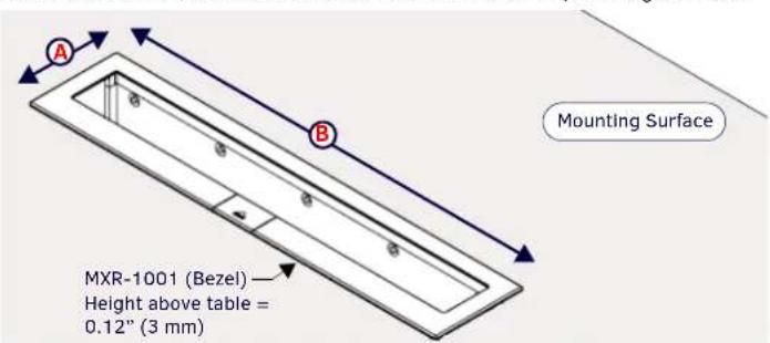
FIG. 2 ABOVE-SURFACE DIMENSIONS OF MXR-1001
DIMENSIONS OF MXR-1001
| Length of “A”: | 2.405” (61.09 mm) |
| Length of “B”: | 11.142” (283.00 mm) |
Below-Surface Dimensions of the MXR-1001
When locating the position of the cutout, it is important to understand the area required beneath the mounting surface by the MXR-1001 assembly when installed. Be sure to allow sufficient room for the aluminum chassis as well as the mounting clamps. FIG. 3 provides a top view of an installed MXR-1001, to indicate the area required below the mounting surface for the chassis and mounting clamps:
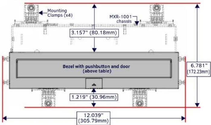
FIG. 3 MXR-1001: TOP VIEW, INDICATING AREA REQUIRED BELOW THE MOUNTING SURFACE
Note: Be sure to allow sufficient room (at least a few inches) to access the two screws that attach each side of the MXR-1001 bezel to the chassis.
FIG. 4 indicates the below-surface depth requirements for the MXR-1001 (side view):
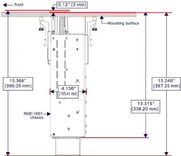
FIG. 4 DIMENSIONS OF THE MXR-1001 (SIDE VIEW, BELOW THE MOUNTING SURFACE)
- MXR-1001 requires a mounting surface thickness between 0.5" (13 mm) to 2" (51 mm).
• The MXR-1001 will have a total depth of 15.366" (390.248 mm).
Hole Cutout Dimensions for the Mounting Surface
Refer to FIG. 5 and the following table for the dimensions of the actual hole cut out in the mounting surface, resulting from using the Router Guide and required accessories:
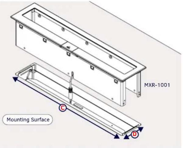
FIG. 5 HOLE CUTOUT DIMENSIONS FOR THE MOUNTING SURFACE
| HOLE CUTOUT DIMENSIONS FOR THE MOUNTING SURFACE | |
| Length of "C": | 1.984" (50.39 mm) |
| Length of "D": | 10.701" (271.81mm) |
Preparing the HydraPort Installation Router Guide
- Cut two 1/2-inch x 4-inch strips of soft, finished wood. The wood strips should be long enough to span the distance from the installation location to the edges of the mounting surface.
- Use four or more short lock nut screws to secure the router guide to the wood strips (FIG. 6):
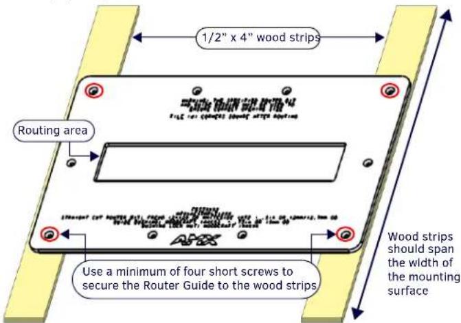
FIG. 6 SECURING THE ROUTER GUIDE
CAUTION: To avoid damaging the mounting surface, do not allow the screws to protrude through the bottom of the wood strips.
Preparing the Mounting Surface
- Mark the desired mounting location on the mounting surface.
- Place the router guide/wood strip assembly on the mounting surface, and center the assembly on the mounting location.
- Position a sheet of soft wood beneath the mounting surface to "sandwich" the mounting surface with soft wood. This will protect both sides of the mounting surface during installation (FIG. 7):
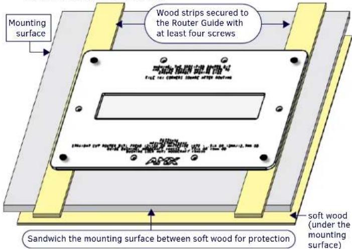
FIG. 7 POSITION THE ROUTER GUIDE AND PROTECTIVE SOFT WOOD STRIPS FOR INSTALLATION Note: For additional protection of the mounting surface, place a layer of soft, thick cloth between the wood strips and the surface.
- Once positioned, secure the router guide/wood strip assembly to the mounting surface and under-surface wood with C-clamps.
Cutting the Hole In the Mounting Surface
CAUTION: Wear safety glasses when operating the router. Failure to comply may result in eye injury.
Use the specified guide bushing and router bit (not included):
• Guide Bushing: Woodcraft 144693 (.75" or 19 mm OD)
- Router Bit: Straight-Cut Router bit: Freud 12-128 or Whiteside 1072 (0.5" or 12mm / 12.7mm OD)
- Carefully measure the mounting surface to locate the desired position of the MXR-1001.
- Use the appropriate Installation Router Guide to mark the edges of the cutout.
-
Carefully cut the opening in the table surface with the router.
-
Note that very little clearance exists between the MXR-1001 and the hole cutout in the mounting surface.
• Take care to align the cutout carefully with the edges or other appropriate features in the table or mounting surface. - If the cutout is misaligned, the installed unit will be misaligned.
• Take care to ensure that the top surface of the mounting surface is not damaged beyond the width of the trim bezel as the cutout is made. - Use an appropriate drill and drill bit to make a starting hole within the boundary of the cutout. Use an appropriate saw, such as a jigsaw to finish the cutout.
- Make sure cutting tool used is appropriate for the material to be cut and will not tear or chip the top surface.
-
Note that the process of making the cutout will create substantial dust and prepare the environment appropriately.
-
File the four corners of the routing area square after routing.
Additional Documentation
- For additional instructions and detailed installation drawings for the MXR-1001, refer to the MXR-1001 Installation Guide (available at www.amx.com).
• Detailed specifications drawings for the HPX-AC-TMPLT router guides are available to download from www.amx.com.
- Selecting a Suitable Location for the MXR-1001
- Above-Surface Dimensions
- Below-Surface Dimensions of the MXR-1001
- Hole Cutout Dimensions for the Mounting Surface
- Preparing the HydraPort Installation Router Guide
- Preparing the Mounting Surface
- Cutting the Hole In the Mounting Surface
- Additional Documentation
Brand : AMX
Model : MX-AC-TMPLT-MXR10
Category : Cutting machine