
MX-FR33L - Switch Lightware - Free user manual and instructions
Find the device manual for free MX-FR33L Lightware in PDF.


| Product Type | AV matrix switcher |
| Model | MX-FR33L |
| Brand | Lightware |
| Dimensions (W x H x D) | 19" x 1U x 12" (482 x 44 x 305 mm) |
| Weight | 4.5 kg (9.9 lbs) |
| Power Supply | 100-240 VAC, 50/60 Hz, internal |
| Power Consumption | 40 W (max) |
| Video Inputs | 3x HDMI, 3x DisplayPort |
| Video Outputs | 3x HDMI |
| Max Resolution | 4K@60Hz 4:4:4 |
| Control Interface | Ethernet, RS-232, USB, IR |
| Cooling | Fanless (passive) |
| Mounting | 19" rack-mountable, 1U |
| Operating Temperature | 0°C to 40°C (32°F to 104°F) |
| Storage Temperature | -20°C to 60°C (-4°F to 140°F) |
| Humidity | 10% to 90%, non-condensing |
| Warranty | 3 years limited |
Frequently Asked Questions - MX-FR33L Lightware
User questions about MX-FR33L Lightware
0 question about this device. Answer the ones you know or ask your own.
Ask a new question about this device
Download the instructions for your Switch in PDF format for free! Find your manual MX-FR33L - Lightware and take your electronic device back in hand. On this page are published all the documents necessary for the use of your device. MX-FR33L by Lightware.
USER MANUAL MX-FR33L Lightware
LIGHTWARE

Quick Start Guide
MX-FR9, MX-FR17, MX-FR33L MX-FR33R, MX-FR65R, MX-FR80R
Introduction
The MX series matrix routers are the highest performance, modular expandable DVI and HDMI compliant switchers, available in five different frame sizes. The built-in sophisticated software and hardware features make these routers the most flexible integrated solution for AV professionals and high-end home theatre applications.
Hybrid Modular Matrix Concept
Lightwave's hybrid modular matrix switchers allow building custom I/O sizes which meet the user's requirements. Different types of input and output boards give the maximum flexibility for rental and installation signal transmission. The hybrid architecture allows signal routing between boards even if they have different connectors. This way any input can be routed to any or more outputs if the output interface is capable of transmitting the signal.
Front View

① The first panel of the main switchers look almost the same. The only difference is the number of source and destination buttons.
Rear View

① A01-FR33L, A01-FR17, and A01-FR9 frames contain a power supply and that is built into the motor frame and not redundant.
Front View Legend
1 Output Lock Locks and projects one or more outputs.
2 Control Lock Disables or enables front panel operations. Red light means
the switching and function bellors are disabled.
Sources Buttons to select an input, to select a preset number or to
view the state of the selected input port.
EDID Mode The EDID Mode can be (de)activated by the button. The
luminated button shows that the mode is active.
Take) Auto Switching between Take and Autotake working modes; keep
the button pressed for 3 seconds to toggle the modes.
6 Preset buttons performing preset operations (Load and Save).
Signal Present The Signal Present Mode can be (detactivated by the button)
The illuminated button shows that the mode is active
Destinations Buttons to select an output or to see the state of an output.
USB Control USB connection for Lightware Device Controller Software
Menu Display Displays status information and menu operation
10. Hany Navigation
Status LEDs: 7.1.1.2.3.4.5.6.7.8.9.10.11.12.13.14.15.16.17.18.19.20.21.22.23.24.25.26.27.28.29.30.31.32.33.34.35.36.37.38.39.40.41.42.43.44.45.46.47.48.49.50.51.52.53.54.55.56.57.58.59.60.61.62.63.64.65.66.67.68.69.70.71.72.73.74.75.76.77.78.79.80.81.82.83.84.85.86.87.88.89.90.91.92.93.94.95.96.97.98.99.100
- Status LEDs Power LED indicates that the unit is positive blinking LED indicates normal operation
① Two rack sets are supplied with the product, which are fired on the left and right side of the frame. These sets allow mounting the device as a standard rack and installation.
Rear View Legend
Status LEDs LED indicators for internal DC power voltages, and alarm.
2 DIP Settings Special sellings can be made with these switches
3 Alarm Out Standard SMPTE 269M alarm output with BVC connector.
Preview Out Dull output connector, which is directly composed to a partum
output - see the table below.
5 Test Input OVI input connector, which can be configured as an
alternative for a certain input - see the attached table.
RS-232 Port 9 pole D-sub female connector for a standard RS-232 port.
⑦ Ethernet Port Standard RJ45 connector. This port can be connected to a
computer directly or in LAN via switchboard.
Reset Rebooks the malits; the same as switching it off and on again
CPU Live CPU for LED links to indicate normal operation.
Input Boards
- Power Supplying - Unit type data for power, work, and available in
Power Supplied Hot Swap Sinks for Power Supply Units - Available in HY FR200, MY FR250 and MY FR250 matrix switches
Output Boards Vascular output board sints.
Powering On
Connect the power cord to AC input of the Power Supply Units (PSU). After switching the mains switch to the 1 position the router starts up. If the mains switch is not available or it was in the 1 position, then the matrix starts up immediately when the power cord is connected to the AC source. During the initial self-test and loading of the latest settings, Booting... appears on the LCD screen and the router reinds its last configuration.
① After switching ON, the router retains the latest settings that were used before it was switched off. The router has an internal emergency memory that stores all current settings and its configurations.
Redundant Power Supplies
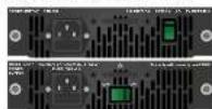
FR30H, FR55R, and FR33R frames contain redundant PSUs which can be removed or installed during operation. Depending on the router's configuration (number and type of 10 boxes) one or two PSUs are needed to operate. The extra PSU makes the system resturant. Please consult Lightware support about your system configuration to ensure redundancy. If more than one PSU is needed for supplying the matrix, make sure that the second PSU gets power not later than 10 seconds after the first one is plugged in to prevent overload on the first PSU.
New PSU for MX-FR33R
Two types of PSUs exist for FR23R frames. Both can supply the frame, but the two units are not interchangeable with each other. ▲ Pay attention to install the same type of PSUs in a matrix!
Board Replacement
Please pay attention to the protection against electrostatic discharge when touching a board! Do not touch the electrical components on the board as the electrostatic discharge may damage them!
Please check the orientation of the slots! The input and output slots and boards have a different type of connectors.
The steps of replacing an input or output board are the followings:
- Switch off the matrix.
- Disconnect all the cables from the rear side of
the affected board. - Loose the hung screws on the rear side of the
Brain (see the true arrows on the right). - Part of the cord and put it in an ESD-sale
- Place the new board into the desired empty slot. Be careful when you insert the board into the socket connector.
- Tighten the screws to fix the board to the frame.
- Connect the necessary cables to the boards and switch on the matrix.
B. Carried to the mark using Lightwave Device Controller to set the necessary pin parameters.
To fill all slots or place a blank plate on a not-used slot is highly recommended (MX-SLANK-10, part no: 52406115).
Further Information
The document is valid with the following firmware version: 3.5.0
The User's manual of this appliance is available on www.lightware.eu.
See the Downloads section on the website of the product
Contact Us
sales@ghware.s
+36 1 255 3800
support@lightware.eu
+3612553810
Lightware Visual Engineering LLC.
Pelordy 16, Budapest H-1071, Hungary
Oct. 12
1720.06
Box Contents


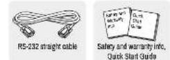


1 supplied with MX-FR23R
2 supplied with boards with 6-pole Analog audio port
*Jumper blocks and PSU-12VP are supplied with TPS boards
*PSU-48VP2-120 is supplied with MX-4TPS2-4HDM boards assembled with PoE add-on
- PSU-18VP2-220 is supplied with MX-TPS2 Boards assembled with PCE add-on
The regular frame includes:
- Router CPU board (MX-CPU2).
- Router input and output boards (depends on the ordered configuration).
- Power supply units depends on the ordered configuration).
- Two rack mounting ears (used to the frame).
Verification
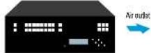
A. To ensure the correct ventilation and avoid overheating let enough free space around the appliance, do not cover it and let the ventilation holes free. The following picture shows the direction of the airflow:


1920[06]
If the button luminates in red the switching- and function buttons are disabled. Press the Control lock button to toggle the state.
When the front panel buttons are locked, remote control (RS-232, USB Ethernet) is still available.
LDC Menu - Navigation
The front panel LCD has 4 lines and 20 characters in each line. The up and down buttons can be used to stock between the menu items. The enter button steps in a submenu or saves changes. The escape button steps back to the previous menu. The left and right navigation buttons modify the value of the current menu item. The right button steps in the current submenu and the left button steps back to the previous menu.
Menu items can be submenus, values, or checkboxes. The ▼ sign shows the currently selected menu item. Submenus are marked with >>' sign. Changeable values appear between < and > signs. Checkboxes are shown like [*7, where the asterisk indicates it the function is active or not.
| IP settings | >> |
| RS-232 settings | |
| Protocol settings | |
| Input settings |
Front Panel Controls in TAKE Mode
Take mode allows the user to connect or disconnect multiple outputs to an input at once. This mode is useful when the time delay is not allowed between multiple switching. The commands are only realized when the Take button is pressed.
| Switching operations | 1. First press and release the desired source button.The pressed source button and all destination buttonswhen are currently connected to the source lights up. | 1 | 1 | 4 | 5 | 6 |
| 2. Press and release the desired destination buttonswhich have to be disconnected to from the selectedsource. The preselected destination buttons will blink. | 1 | 3 | 4 | 5 | 6 | |
| 3. Press and release Take button; the selected input isswitched to the selected outputs. | ||||||
| Lock an output | 1. Press and release the Output Lock button it starts tobrink and all the buttons of any locked destinations lightup view state. | |||||
| 2. Press and release a destination button; it starts toblink (more destinations can be selected sequentially). | ||||||
| 3. Press and release Take button. The selecteddestinations are now locked. |
Front Panel Controls in AUTOTAKE Mode
Autotake mode is useful when immediate actions must be done or fast switching is needed between sources on a particular destination. In this mode switching occurs immediately upon pressing one of the input selector buttons.
| Switching operations | 1. Press and release the desired destination button.The pressad destination button and the actuallyconnected source button light up green. If no source isconnected (the output is muted), no source button litight up. | |
| 2. Press and release the desired source button. Thswitch action will be executed immediately. Switchingbetween sources to the selected destination can be donedirectly. | ||
| Link an output | 1. Press and release the required destination button.New the secreted destination button and the currentlyconfigured source button light up (view mode). | |
| 2. Press and release the Output Lock button: it lights upin red, and lock function is activated at once. No sourcescan be changed at the locked destination. |

Typical Application - an MX-FR17 with HDMI-TPS-TX97/RX97 ExtendersCONTROL LOCK
![graph TD A["External switch"] -->|LAN| B["External power supply"] C["Laptop"] -->|LAN| B D["HDMI-IPS-TX97"] -->|HDMI| B B --> E["TPS connection CATx up to 170m"] E --> F["PC"] G["Local monitor"] --> H["HDMI"] I["Projector"] --> J["AV Receiver"] K["3.1 speakers"] --> L["Audio"] M["PS-232"] --> N["45-…](/content/2026/05/994205/images/341f2f86423b623dcf252d8fe58b8f2f5b1d28b078b42f7dc524cb05a34f3309.jpg)
Network Settings on the Front Panel
Setting a Dynamic IP Address
-
Navigate to the IP settings menu item and press the Enter button.
-
Use the Up and Down buttons to navigate to the DHCP enable sub-item.
-
Press the Enter to toggle between enable and disable status. If the DHCP is switched off then the IP address can be set by the user.
-
To take effect, navigate to Save settings, then press the Enter.
-
Any changes made in the IP settings menu come alive only when Save settings is executed. To do this, navigate to this item with the Up and Down buttons, and press
Setting a Static IP Address
- Disable DHCP as described above.
-
The four parts of the IP address can be set separately. Use the Left and Right buttons to select the part, then use the Up and Down buttons to change the value of that part.
-
Any change made in the IP settings menu comes alive only when Save settings is executed; navigate to this item with the Up and Down buttons and then press the Enter.
① New IP settings can be applied while an active connection is alive on the Ethernet port but in this case, the active connection will be closed automatically. To recover the Ethernet port needs to be used again.
Factory Default Settings
The settings and parameters can be set to factory default as follows:
- Navigate to Factory reset menu.
- Press the enter button to select the desired component (IP reset, IO card reset, EDID reset, HDCP key reset, Protocol reset, All reset).
| IP address (static) 392.368.254.254 | |
| Subnet mask 255.255.0.0 | |
| Static gateway | 0.0.0.0 |
| DHCP | disabled |
| TCP/IP port no. | 10001 |
| RS-232 port setting | 57800 DAUD, 5, N, 1 |
| Emulated EDD | static FN0 at all inputs |
| Crosspoint settings | all outputs connected to input 1 |
| CPU test input - color range | no change |
| CPU test input - HDCP enable | yes |
| CPU preview output - video mode | auto |
| CPU preview output - colorspace | auto |
| CPU preview output - color range | auto |
| CPU preview output - LPCM subsample | auto |
| CPU preview output - HDCP | auto |
| Input/Output board setting | depends on the installed board |
MX-CPU2 Processor Board
There is a CPU board in the router which is necessary for the frame to work. That board is responsible for controlling the matrix and storing the settings.
Test Input and Preview Output Ports
The MX-CPU2 board has a TEST DVI input, and a PREVIEW DVI output port. Although these ports have special functions they can be used as normal I/O ports including HDMI and HDCP capability.
MX-FR80R and MX-FR85R
Used in the MX-FR30R (and MX-FR65R) router frame, the Preview output is directly connected to the 80th output port with a DWI splitter. Therefore, that port always outputs
the same signal as the 80th output, even if it uses a different interface (IP, OPT, etc.). The 80th input port of the crosspoint is multiplexed between the Test input port and the 8th port of the 10th input board. This switch is independent of the crosspoint state. The selected port (Test input or input board #10) will be available as the 80th input on the crosspoint switch. Other Frames
All other frames use the Test Input and Preview output just like any other ports. These ports are referred as the last port in the crosspoint.
The Remote Power Feature of MX-TPS Boards
⚠ Incorrect configuration can DAMAGE the devices! In this case the devices cannot be repaired under warranty.
MX-TPS boards can be configured to remotely power the connected TPS-TX/RX95 extenders. To use remote powering you will need the followings:
- PSU-12VP (part no: 91340007) external PSU. - Jumper park (part no: 81340008).
Cable length
Please note, that the distances are 20% shorter if the remote powering is used in the case of AWG 25 CAT cables. The remote powering can be enabled or disabled for each separately. Some of the ports can have remote powering enabled for Lightware extenders. While other ports can have remote powering disabled and be used with HDBaseT™ comp devices.
Important Instructions
- Never connect any third party devices. When remote power is active the ports are NOT HDBase™ compliant.
- Below jumper setting is compatible only with Lightware TPS-TX/RX96 devices.
- The discontinued TPS-TX/RX80 extenders cannot be powered with the TPS boards.
Remote Operation
The matrix can be controlled through various interfaces remotely. The feature allows using functions which are not accessible via the front panel. Also, it helps system integrators and operators to control multiple devices in a complicated system by a single user interface. Control Interfaces
The User can connect to the matrix through the Ethernet serial, or USB port. After establishing the connection, there is no difference between the connection types generally.
① Ethernet port can be connected to a LAN hub, switch or router with a UTP patch cable. If connecting to a computer directly, a crosslink UTP cable has to be useful
| User Interface | Ethernet Port | RS-232 Port | USB Port |
| Lightwave Device Controller | √ | √ | √ |
| Built-in Website | √ | - | - |
| Third-party Control System | √ | √ | - |
Multiple Simultaneous Connections
Ethernet and Serial connections can be used at the same time. However, only one connection is allowed for Lightware Device Controller (LDC) via the Ethernet port. Control Protocols
Matrix routers can be controlled with multiple control protocols. Lightning routers have a special protocol but to interoperate with third-party devices, a secondary protocol is also provided. For detailed information about control protocols, read the User's manual or the device.
Port Settings
The port settings of each type of boards are stored at dedicated memory places on the MX-CPU2 board. If an input/output board is replaced to another one, the stored settings will be applied to the new board according to below table:
| Mute-, lock-, and crosspoint states | Port-specific parameters and settings | |
| Same type of board* has been installed into the same slot previously | Restored from last used board | Restored from previous same type of board* |
| No such type of board has been installed into the given slot previously | Restored from last used board | Factory default settings and parameters are loaded |
* Some type of board: It does not matter if any add-on (like Audio or PoE extensor) is installed on the board. E.g. MX-HDMI-3D-OB-A and MX-HDMI-3D-OB boards are handled as 'same types'.

Configuration Steps
-
Power off the matrix and take the desired board out to access the pin headers.
-
Locale the pin headers on the board. They are next to the RJAS receptacles (TPS ports).
-
Place the jumper block on the desired pin header(s); see the yellow circle.
-
Place the matrix board into the frame and tighten the screws. Connect the CATx cables.
-
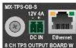
Connect the PSU-12VP power supply to the DC IN connector on the left side of the board. The connected extenders - where the Jumper block is set to enabled position on the board as well as in the extender - will power up instantly.
- Power and power matrix connecting TDP follow a nominal transmission
d. Power up the RMS and check the TPS links and signal transmission.
The Remote Power Feature of MX-TPS2 Boards (PoE-compatible)
Remote powering option for a connected PoE-compatible TPS extender is available in the case of MX-TPS2 boards. To use the function you will need the supplied external PSU.
▲ TPS-TX/RX30 and TPS-TX/RX95 devices do not comply with the PoE standard and cannot be powered this way.


- INTRODUCTION
- HYBRID MODULAR MATRIX CONCEPT
- FRONT VIEW LEGEND
- REAR VIEW LEGEND
- POWERING ON
- REDUNDANT POWER SUPPLIES
- NEW PSU FOR MX-FR33R
- BOARD REPLACEMENT
- 1 SUPPLIED WITH MX-FR23R
- VERIFICATION
- LDC MENU - NAVIGATION
- FRONT PANEL CONTROLS IN TAKE MODE
- FRONT PANEL CONTROLS IN AUTOTAKE MODE
- NETWORK SETTINGS ON THE FRONT PANEL
- SETTING A DYNAMIC IP ADDRESS
- SETTING A STATIC IP ADDRESS
- FACTORY DEFAULT SETTINGS
- MX-CPU2 PROCESSOR BOARD
- TEST INPUT AND PREVIEW OUTPUT PORTS
- MX-FR80R AND MX-FR85R
- THE REMOTE POWER FEATURE OF MX-TPS BOARDS
- CABLE LENGTH
- IMPORTANT INSTRUCTIONS
- REMOTE OPERATION
- MULTIPLE SIMULTANEOUS CONNECTIONS
- PORT SETTINGS
- CONFIGURATION STEPS
- THE REMOTE POWER FEATURE OF MX-TPS2 BOARDS (POE-COMPATIBLE)
Brand : Lightware
Model : MX-FR33L
Category : Switch