
10ACT01 - Compteur / Minuteur Daytronic - Free user manual and instructions
Find the device manual for free 10ACT01 Daytronic in PDF.


| Product Type | Counter/Timer Card |
| Model | 10ACT01 |
| Brand | Daytronic |
| Modes of Operation | Frequency, Period, Counter (Totalizer), Timer |
| Input Types | Low-level (0–100 kHz), TTL-level (100–3200 kHz) |
| Frequency Range (Full Scale) | 3.2 kHz to 3.2 mHz (low-level limited to 100 kHz; TTL up to 3200 kHz) |
| Frequency Resolution | 0.1 Hz to 100 Hz (selectable via RNG command) |
| Period Range (Full Scale) | 0.32767 ms to 32767 ms (depending on number of cycles averaged) |
| Count Increment | 1, 10, or 100 (selectable via RNG command) |
| Maximum Count | 3,276,700 (with increment 100) |
| Timer Range (Full Scale) | 0.32767 sec to 327670 min |
| Timer Resolution | 10 μs to 10 min (selectable via RNG command) |
| Input Amplifier Sensitivity | 5 settings: 10 V–200 V, 3 V–60 V, 1 V–20 V, 300 mV–6 V, 100 mV–2 V |
| Connector | 20-pin I/O connector (mates with Daytronic No. 60322) |
| Logic Inputs | Negative-true: Reset (Pin 5), Latch Enable (Pin 6), Input Enable (Pin B) |
| Power Supply | +5 VDC and -5 VDC excitation from DataPAC mainframe |
| Compatibility | Daytronic DataPAC system (plug-in card) |
| Slave Capability | Multiple cards can be synchronized via solder jumper and wire-wrap interconnection |
| Noise Suppression | Capacitive coupling pins (0.1 μF on Pin E, 10 μF on Pin F) |
| Command Interface | MNEMONIC commands (TYP, RNG, SEN, INC, COH, COU, COR, COC, EID, EIE) |
| Installation | Plug into DataPAC mainframe slot; refer to Appendix B |
Frequently Asked Questions - 10ACT01 Daytronic
User questions about 10ACT01 Daytronic
0 question about this device. Answer the ones you know or ask your own.
Ask a new question about this device
Download the instructions for your Compteur / Minuteur in PDF format for free! Find your manual 10ACT01 - Daytronic and take your electronic device back in hand. On this page are published all the documents necessary for the use of your device. 10ACT01 by Daytronic.
USER MANUAL 10ACT01 Daytronic
By means of the TYPE (TYP) command, the Model 10ACT01 Counter/Timer Card can be made to function in any of the four modes of operation described below.
In all but the TIMER mode, the "events" being counted by the 10ACT01 are waveform pulses, AC or unipolar, delivered to the 10ACT01's rear I/O CONNECTOR by an external pulse transformer transducer with two-wire isolated windings (turbine flowmeter, tachometer pickup, etc.), by a transistor or logic-circuit driver, or by a similar signal source.
The Model 10ACC-4 Totalizer Card can accept up to four independent TTL pulse inputs, and functions only in the COUNTER (or TOTALIZER) mode. It is particularly useful in assembly-line applications that require the accurate counting of large numbers of parts.
1. FREQUENCY MODE
In this mode, the 10ACT01 counts events per unit time, and can thus be used for direct frequency or rpm measurement. As explained in Section b.2(b), below, the RANGE (RNG) command lets you select the desired full-scale frequency range (with corresponding resolution), plus the specific time base during which "events" (pulses) are to be counted.
2. PERIOD MODE
In this mode, the 10ACT01 calculates the average time period required for the occurrence of 1, 10, 60, 100, or 120 pulse "events" (cycles). Such measurements are particularly useful when dealing with relatively low flow or speed signals, where a conventional frequency-to-voltage conversion is impractical. The full-scale reading (along with corresponding resolution and minimum frequency input) is selectable via the RANGE (RNG) command, as explained in Section b.2(b), below.
3. COUNTER (TOTALIZER) MODE
In this mode, the 10ACT01 or 10ACC-4 counts all perceived "events" (pulses) by an increment of 1, 10, or 100 (with a respective full-scale count reading of 32767, 327670, or 3276700), selectable via the RANGE (RNG) command (see Sections b.2(b) and d.2(a), below).
Special MNEMONIC COMMANDS, described in Section c.2, below, allow the operator or computer to increment the counter at any time, to disconnect or reconnect the external input, to hold the existing displayed count, to instantly update ("release") the displayed count, to reset the counter to zero, and to clear the counter (to resume normal counting from zero).
You can also use specific logic inputs to the 10ACT01's or 10ACC-4's I/O CONNECTOR to initiate a "hold," "release," "resetting," or "clearing" of the counter. In addition, the 10ACT01 lets you disable and re-enable the external input via logic-signal command, when the card is in COUNTER mode.
4. TIMER MODE
In this mode, the Model 10ACT01 provides precision timing by counting pulses generated by its own internal clock. As explained in Section b.2(b), resolution is selectable via the RANGE (RNG) command from 10 microseconds to 10 minutes, with corresponding full-scale readings from 0.32767 second to 327670 minutes.
Special MNEMONIC COMMANDS, described in Section c.2, below, allow the operator or computer to disconnect or reconnect the external input, to hold the displayed time value, to update ("release") the displayed time value, to reset the timer to zero, and to clear the time (to resume normal timing operation from zero). You can also use logic inputs to the 10ACT01's I/O CONNECTOR to disable and re-enable the external input, or to initiate a "hold," "release," "resetting," or "clearing" of the timer.
1. 10ACT01 CONNECTIONS
a. GENERAL CONSIDERATIONS
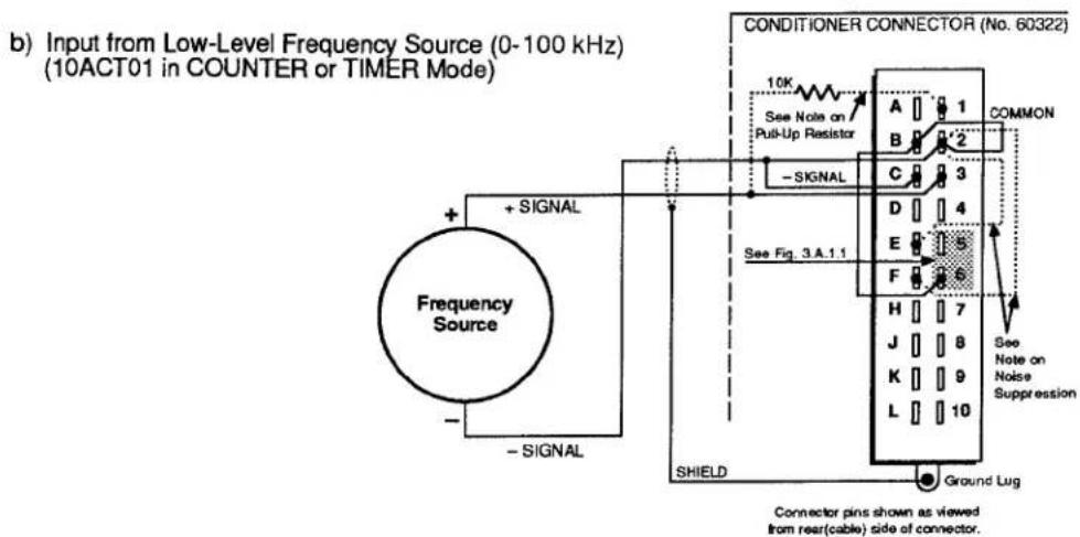
The Model 10ACT01's 20-pin I/O CONNECTOR mates with Daytronic CONDITIONER CONNECTOR No. 60322 (shown in Fig. 1.E.1). Pin functions are given in Table 3.A.1.1. Cabling is shown in Fig. 3.A.1.2 for three different types of input:
- a nonexcited low-level frequency or rpm signal (0 to 100 kHz);
- a TTL-level pulse or square-wave signal (0 to 3200 kHz);
- output from a zero-velocity speed sensor with excitation of nominal +5 V-DC.
For low-level and zero-velocity inputs, connections are shown for both FREQUENCY/PERIOD and COUNTER/TIMER operation of the 10ACT01.
Specifications for the input pulse signal are identical to those given for the Model 10A40 Frequency Input Conditioner Card. The analog-input voltage range may be set, independent of the "mode of operation," via the SENSITIVITY (SEN) command (see Section b.2(c)).
Note that the 10ACT01's Pin B may have either of two functions, depending on the nature of the input signal:
- When the input is low-level (0 to 100 kHz), Pin B serves as a negative-true enabling pin. That is, the +SIGNAL input, which should be connected to Pin 3, will be enabled only when Pin B is at a Logic 0 level. Therefore, Pin B must be tied to COMMON (Pin 2) in order for the 10ACT01 to operate.
When the 10ACT01 is in COUNTER or TIMER mode, Pin B may serve as a controllable gate, to enable and disable the external input as desired. To be so used, however, it must also be tied to the LATCH ENABLE input (Pin 6). See Section c.3, below. - When the input is TTL-level (100 to 3200 kHz), it should be received at Pin B. In this case, the +SIGNAL (Pin 3) should be tied to COMMON (Pin 2), and the -SIGNAL (Pin C) should be tied to the -5 V-DC EXCITATION (Pin A).
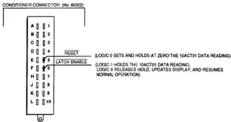
The 10ACT01's Pins 5 and 6 provide negative-true logic inputs for the remote control of COUNTER and TIMER operation (see Fig. 3.A.1.1). These logic commands may be "ORed" with corresponding MNEMONIC COMMANDS, as explained in Section c.2, below.
Fig. 3.A.1.1 Model 10ACT01 Logic Inputs for Counter/Timer Control
b. SUPPRESSION OF NOISE IN LOW-FREQUENCY INPUT
False triggering can sometimes occur, especially at the low-frequency input range, because of stray pickup of frequencies outside the common-mode range. Capacitive coupling of the frequency input to ground can in such cases serve to suppress unwanted signal noise.
If you find your frequency reading to be unacceptably unstable or "noisy," you should connect either Pin E or Pin F to SIGNAL COMMON (Pin 2). Pin E provides 0.1-microfarad capacitance; Pin F provides 10-microfarad capacitance. Note that connection of Pin E is recommended for zero-velocity sensors (see Fig. 3.A.1.2(d,e)).
C. PULL-UP RESISTOR
When used with an open-collector type sensor, the Model 10ACT01 requires a pull-up resistor (typically 10 kilohms) between the +SIGNAL and the +5 V-DC EXCITATION (Pin 1).
Fig. 3.A.1.2 Model 10ACT01 Cabling

3.A.1 Counter/Timer Functions

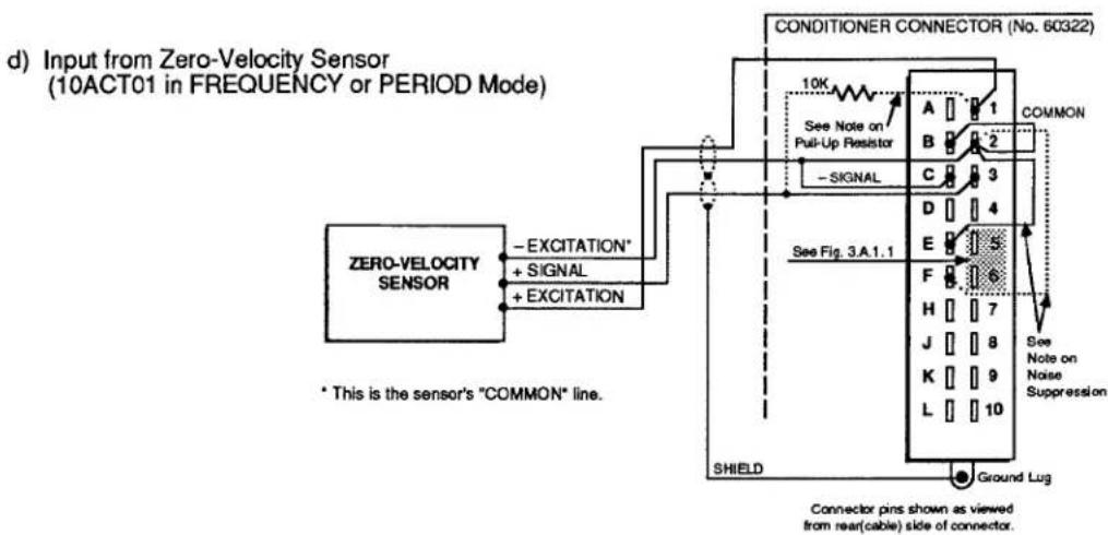

Table 3.A.1.1
Model 10ACT01 Pin Assignments
| I/O CONNECTOR Pin No. | Line Function |
| 1 | +EXCITATION (+5 V-DC) |
| A | -EXCITATION (-5 V-DC) |
| 2 | COMMON |
| B | (1) INPUT ENABLE(2) TTL-LEVEL INPUT |
| 3 | +SIGNAL (LOW-LEVEL) |
| C | -SIGNAL |
| 4,D | N/C |
| 5 | RESET |
| E | 0.1-MICROFD COUPLING |
| 6 | LATCH ENABLE |
| F | 10-MICROFD COUPLING |
| 7-L | N/C |
2. 10ACT01 CONFIGURATION
a. SETTING 10ACT01 MODE: TYP COMMAND
To select the desired mode of operation for the Model 10ACT01 that uses DATA CHANNEL No. x, turn ON the DataPAC's EEPROM Write Protect Switch and enter a TYPE (TYP) command of the general form
$$ \text { TYP } x = v [ \text { CR } ] ^ {*} $$
where "v" is the appropriate two-character (hexadecimal) TYPE code, as given in the following table:
Table 3.A.1.2
| 10ACT01 Mode of Operation | Channel Type Code |
| FREQUENCY MODE (EVENTS PER UNIT TIME) | C0 |
| PERIOD MODE | C1 |
| COUNTER (TOTALIZER) MODE | C2 |
| TIMER MODE | C3 |
b. SETTING RANGE AND RESOLUTION: RNG COMMAND
NOTE
You will normally NOT have to "locate" the 10ACT01 DATA CHANNEL via the LOCATE (LCT) command, unless you are "reconfiguring" the channel or are installing the 10ACT01 card yourself—in which case see Appendix C.
3.A.1 Counter/Timer Functions
To select the desired combination of range and resolution for the Model 10ACT01 that uses DATA CHANNEL No. x, you should enter a RANGE (RNG) command of the general form
$$ \mathbf {R N G} \mathbf {x} = \mathbf {n} [ \mathbf {C R} ] ^ {*} $$
Allowable values for the number "n" will depend on the particular mode of operation selected for your 10ACT01 via the TYPE (TYP) command, above. Note that a default value for "n" exists for each of the four modes. The default range will be in effect until the first application of the RNG command.
1. FREQUENCY MODE (TYPE "C0")
When using your 10ACT01 for frequency or rpm measurement, you will select the appropriate full-scale frequency range, with corresponding resolution, and also the desired time base of the measurement. Enter in the above RNG command the "n" value for the range configuration you have selected.
Table 3.A.1.3.
10ACT01 Ranges for FREQUENCY MODE
| Full-Scale Range | Resolution | Time Base | "n" Value |
| 3.2 kHz | 0.1 Hz | 10 sec | 1 |
| 32 kHz | 1 Hz | 1 sec | 2^* |
| 32 kHz | 1 Hz | 10 sec | 4 |
| 320 kHz** | 10 Hz | 0.1 sec | 3 |
| 320 kHz** | 10 Hz | 1 sec | 5 |
| 320 kHz** | 10 Hz | 10 sec | 7 |
| 3.2 mHz** | 100 Hz | 0.1 sec | 6 |
| 3.2 mHz** | 100 Hz | 1 sec | 8 |
* Default range.
** This range exceeds the 100-kHz capability of the 10ACT01's low-level frequency input. In such cases, the TTL INPUT (Pin B) should be used (see Section b.1 for details).
2. PERIOD MODE (TYPE "C1")
When using your 10ACT01 for period measurement, you will select the appropriate full-scale reading, with corresponding minimum frequency input and resolution, and also the number of input cycles over which an average period value is to be calculated. Enter in the RNG command the "n" value for the range configuration you have selected.
Table 3.A.1.4.
10ACT01 Ranges for PERIOD MODE
| Full-Scale Reading (millisec) | No. of Cycles Averaged | Minimum Input Frequency | Resolution | "n" Value |
| 32767 | 1 | 0.032 Hz | 1 millisec | 1 |
| 32767 | 10 | 0.032 Hz | 1 millisec | 2 |
| 32767 | 100 | 0.032 Hz | 1 millisec | 3 |
| 27305 | 120 | 0.037 Hz | 1 millisec | 4 |
| 5461 | 60 | 0.183 Hz | 1 millisec | 5 |
| 3276.7 | 1 | 0.32 Hz | 100 microsec | 6 |
| 3276.7 | 10 | 0.32 Hz | 100 microsec | 7 |
| 3276.7 | 100 | 0.32 Hz | 100 microsec | 8 |
| 2730.5 | 120 | 0.37 Hz | 100 microsec | 9 |
| 546.1 | 60 | 1.83 Hz | 100 microsec | 10 |
| 327.67 | 1 | 3.2 Hz | 10 microsec | 11* |
| 327.67 | 10 | 3.2 Hz | 10 microsec | 12 |
| 327.67 | 100 | 3.2 Hz | 10 microsec | 13 |
| 273.05 | 120 | 3.7 Hz | 10 microsec | 14 |
| 54.61 | 60 | 18.3 Hz | 10 microsec | 15 |
| 32.767 | 1 | 32 Hz | 1 microsec | 16 |
| 32.767 | 10 | 32 Hz | 1 microsec | 17 |
| 32.767 | 100 | 32 Hz | 1 microsec | 18 |
| 27.305 | 120 | 37 Hz | 1 microsec | 19 |
| 5.461 | 60 | 183 Hz | 1 microsec | 20 |
| 3.2767 | 10 | 320 Hz | 100 microsec | 21 |
| 3.2767 | 100 | 320 Hz | 100 microsec | 22 |
| 2.7305 | 120 | 370 Hz | 100 microsec | 23 |
| 0.5461 | 60 | 1832 Hz | 100 microsec | 24 |
| 0.32767 | 100 | 3200 Hz | 10 microsec | 25 |
NOTE
When selecting a suitable range for period measurement, keep in mind that the update interval for the scanned period reading will be equal to
No. of Cycles Averaged
Frequency Input
For example, if you apply a command of
$$ \text { RNG } 4 8 = 1 7 [ \mathrm{CR} ] ^ {*} $$
for the 10ACT01 using Channel No. 48, and the applied frequency input is, say, 1 kHz, then your period measurement will be up- dated every hundredth of a second, since
$$ \frac {1 0}{1 0 0 0 \mathrm{Hz}} = 0. 0 1 \mathrm{sec} $$
3. COUNTER MODE (TYPE "C2")
When using your 10ACT01 as an "event" counter (or "totalizer"), you will select an appropriate full-scale count, with corresponding count increment. Enter in the RNG command the "n" value for the range configuration you have selected.
Table 3.A.1.5.
10ACT01 Ranges for COUNTER MODE
| Full-Scale Count | Count Increment | "n" Value |
| 32767 | 1 | 1* |
| 327670 | 10 | 2 |
| 3276700 | 100 | 3 |
* Default range.
4. TIMER MODE (TYPE "C3")
When using your 10ACT01 as a timer, you will select an appropriate full-scale reading, with corresponding resolution. Enter in the RNG command the "n" value for the range configuration you have selected.
Table 3.A.1.6.
10ACT01 Ranges for TIMER MODE
| Full-Scale Reading | Resolution | "n" Value |
| 0.32767 sec | 10 microsec | 1 |
| 3.2767 sec | 100 microsec | 2 |
| 32.767 sec | 1 millisec | 3 |
| 327.67 sec | 10 millisec | 4 |
| 3276.7 sec | 100 millisec | 5 |
| 32767 sec | 1 sec | 6* |
| 327670 sec | 10 sec | 7 |
| 3276700 sec | 100 sec | 8 |
| 32767 min | 1 min | 9 |
| 327670 min | 10 min | 10 |
* Default range.
C. SETTING 10ACT01 INPUT-AMPLIFIER SENSITIVITY: SEN COMMAND
You can set the input-amplifier sensitivity of the Model 10ACT01 that uses DATA CHANNEL No. x by applying the SENSITIVITY (SEN) command:
$$ \text { SEN } x = g [ \text { CR } ] ^ {*} $$
where the value of "g" ("gain") to be entered is independent of the mode of operation selected via the TYPE (TYP) command, above. It does, however, set the 10ACT01's analog-input voltage range, as shown in the following table:
| Table 3.A.1.7. | 10ACT01Input Levels | Sensitivity("g") Value |
| 10 V - 200 V | 1 | |
| 3 V - 60 V | 2 | |
| 1 V - 20 V | 3 | |
| 300 mV - 6 V | 4 | |
| 100 mV - 2 V | 5 |
d. "SLAVING" OF MULTIPLE 10ACT01'S
NOTE: THIS PROCEDURE IS NECESSARY ONLY WHEN MULTIPLE 10ACT01'S ARE BEING USED FOR FREQUENCY MEASUREMENTS OF EQUAL TIME BASE.
When more than one 10ACT01 cards are installed in a single DataPAC, you can synchronize their 1.000000-mHz crystal frequency reference by designating one card as "MASTER" and the other(s) as "SLAVE(S)." Unless otherwise specified, all Model 10ACT01's are factory-set for "MASTER" operation. To set a 10ACT01 for "SLAVE" operation, you should
- Make sure the EEPROM Switch is OFF, and then turn OFF DataPAC power.
- Remove the 10ACT01 card to be "slaved" from its slot (see Appendix B).
- Locate the programming jumper pads labelled "S" on "Side 2" of the 10ACT01 board (see Fig. 3.A.1.3).
- Place a solder drop between the jumper pads.
- Reinstall the card.
- IMPORTANT: Before reactivating power, make sure that the DataPAC motherboard's wire-wrap "I/O #1" pin (No. 41) for each mainframe slot containing a Model 10ACT01 is hardwired to the "I/O #1" pin (No. 41) of every other slot containing a 10ACT01 card. All 10ACT01 "I/O #2" wire-wrap pins (No. 42) should likewise be interconnected, as should all 10ACT01 "I/O #3" wire-wrap pins (No. 43). CONTACT THE DAYTRONIC SERVICE DEPARTMENT FOR THE WIRE-WRAP PROCEDURE.
Fig. 3.a.1.3
Model 10ACT01 "Slave" Programming Jumpers

3.A.1 Counter/Timer Functions
1. INCREMENTING THE COUNT: INC COMMAND
By entering the INCREMENT (INC) command, you can cause a Model 10ACT01 in the COUNTER mode (only) to increase its count reading by one increment (1, 10, or 100, depending on the full-scale count selected via the RANGE (RNG) command—see Section b.2(b)).
Thus, to increase by one increment the count reading of the 10ACT01 that uses DATA CHANNEL No. x, simply command
$$ \mathrm{INC} \times [ \mathrm{CR} ] $$
For the application of the INC command to a DOWNLOAD PSEUDOCHANNEL, see Section 2.M.1.
2. COUNTER/TIMER CONTROL
The four following commands are applicable only when the Model 10ACT01 is functioning in the COUNTER or TIMER mode.
NOTE THAT EACH COMMAND AFFECTS ONLY THE SCANNED DATA READING (WHICH, IN MOST CASES, WILL BE A DISPLAYED VALUE). THE 10ACT01 WILL ALWAYS CONTINUE TO ACCUMULATE COUNTS, REGARDLESS OF THE "CONTROL" COMMAND PRESENTLY IN EFFECT, AND OF THE DISPLAYED READING THAT RESULTS FROM THE APPLICATION OF THAT COMMAND.
Note also that the effects of these commands can also be obtained by the application of appropriate logic inputs to the 10ACT01's rear I/O CONNECTOR—but again, only when the 10ACT01 is set for COUNTER or TIMER mode.
a. HOLDING THE COUNT/TIME VALUE: COH COMMAND
To inhibit updating of the scanned data reading of the 10ACT01 that uses DATA CHANNEL No. x, apply the COUNTER HOLD (COH) command:
COH x [CR]
Alternatively, a Logic 1 input at Pin 6 of the 10ACT01's rear I/O CONNECTOR will "hold" the existing scanned data reading. Such an input may be "ORed" with a COUNTER HOLD (COH) command (see also Section c.3, below).
b. UPDATING THE COUNT/TIME VALUE: COU COMMAND
To release the COUNTER HOLD (COH) command, thus instantly updating the scanned data reading of the 10ACT01 that uses DATA CHANNEL No. x, and resuming normal COUNTER or TIMER operation, apply the COUNTER UPDATE (COU) command:
COU x [CR]
Alternatively, a Logic 0 input at Pin 6 of the 10ACT01's rear I/O CONNECTOR will release an existing "hold" condition, instantly updating the display and resuming normal operation. Such an input may be effectively "ORed" with a COUNTER UPDATE (COU) command (see also Section c.3, below).
C. RESETTING THE COUNTER/TIMER: COR COMMAND
To set and hold at zero the scanned data reading of the 10ACT01 that uses DATA CHANNEL No. x, apply the COUNTER RESET (COR) command:
COR x [CR]
If the 10ACT01's data reading is currently being "held" at a nonzero value by a COUNTER HOLD (COH) command or by a Logic 1 at Pin 6, then the application of COUNTER RESET (COR) will not produce a reading of zero. For the resetting of the 10ACT01 to be reflected in the scanned data reading, the COUNTER UPDATE (COU) command must be in effect, and Pin 6 must be at a Logic 0 level.
Alternatively, a Logic 0 input at Pin 5 of the 10ACT01's rear I/O CONNECTOR will set and hold at zero the scanned data reading, if no COUNTER HOLD (COH) command is presently in effect, and if Pin 6 is at a Logic 0 level. Such an input may be "ORed" with a COUNTER RESET (COR) command (see also Section c.3, below).
d. CLEARING THE COUNTER/TIMER: COC COMMAND
To release the COUNTER RESET (COR) command, thereby resuming normal updating (from zero) of the scanned data reading of the 10ACT01 that uses DATA CHANNEL No. x, apply the COUNTER CLEAR (COC) command:
COC x [CR]
Alternatively, a Logic 1 input at Pin 5 of the 10ACT01's rear I/O CONNECTOR will cause the Counter/Timer to resume normal updating (from zero) of the scanned data reading. Such an input may be effectively "ORed" with a COUNTER CLEAR (COC) command (see also Section c.3, below).
3. DISABLING AND ENABLING EXTERNAL INPUT DURING TIMER OPERATION: EID AND EIE COMMANDS
As indicated above, control of the Model 10ACT01's COUNTER or TIMER operation can be accomplished in two ways:
a. by MNEMONIC COMMANDS (COH, COU, COR, and COC), or
b. by appropriate logic inputs to the 10ACT01's rear I/O CONNECTOR.
Both methods of control may be simultaneously in effect, in a "logic-OR" fashion.
In applications where the 10ACT01 functions in the TIMER mode with "ORed" timer control, it is sometimes useful to be able to disable the 10ACT01's external input (including any and all logic commands received at the I/O CONNECTOR), in order to establish strictly internal control of the timing process (via MNEMONIC COMMANDS). You can then re-enable the external input whenever you wish the card to respond as well to external logic-signal commands—as, for example, when you're timing the duration of a switched process state.
To disconnect from the 10ACT01 that uses DATA CHANNEL No. x any and all external signals and logic commands received at its rear I/O CONNECTOR, apply the EXTERNAL INPUT DISABLE (EID) command:
EID x [CR]
3.A.1 Counter/Timer Functions
To cancel the EID command, thus reconnecting all external signals and logic commands received at the I/O CONNECTOR of the 10ACT01 that uses Channel No. x, apply the EXTERNAL INPUT ENABLE (EIE) command:
EIE x [CR]
NOTE: Although the EID and EIE commands will be effective when the 10ACT01 is in either COUNTER or TIMER mode, they are, in general, only useful during 10ACT01 TIMER operation (obviously, disconnection of the external input would only disrupt normal FREQUENCY, PERIOD, or COUNTER operations). Upon application to the 10ACT01 of a TYPE (TYP) or RANGE (RNG) command (Section b.2), the EXTERNAL INPUT ENABLE (EIE) command is automatically in effect.
ALSO NOTE: When the 10ACT01 is in COUNTER or TIMER mode (only), an input of Logic 1 at Pin B of the I/O CONNECTOR will also serve to disable the external input. A Logic 0 at Pin B will then re-enable the external input.
- FREQUENCY MODE
- PERIOD MODE
- COUNTER (TOTALIZER) MODE
- TIMER MODE
- 10ACT01 CONNECTIONS
- a. GENERAL CONSIDERATIONS
- b. SUPPRESSION OF NOISE IN LOW-FREQUENCY INPUT
- PULL-UP RESISTOR
- 3.A.1 Counter/Timer Functions
- 10ACT01 CONFIGURATION
- a. SETTING 10ACT01 MODE: TYP COMMAND
- b. SETTING RANGE AND RESOLUTION: RNG COMMAND
- NOTE
- FREQUENCY MODE (TYPE "C0")
- PERIOD MODE (TYPE "C1")
- COUNTER MODE (TYPE "C2")
- TIMER MODE (TYPE "C3")
- SETTING 10ACT01 INPUT-AMPLIFIER SENSITIVITY: SEN COMMAND
- d. "SLAVING" OF MULTIPLE 10ACT01'S
- INCREMENTING THE COUNT: INC COMMAND
- COUNTER/TIMER CONTROL
- a. HOLDING THE COUNT/TIME VALUE: COH COMMAND
- COH x [CR]
- b. UPDATING THE COUNT/TIME VALUE: COU COMMAND
- COU x [CR]
- RESETTING THE COUNTER/TIMER: COR COMMAND
- COR x [CR]
- d. CLEARING THE COUNTER/TIMER: COC COMMAND
- COC x [CR]
- DISABLING AND ENABLING EXTERNAL INPUT DURING TIMER OPERATION: EID AND EIE COMMANDS
- EID x [CR]
- EIE x [CR]
Brand : Daytronic
Model : 10ACT01
Category : Compteur / Minuteur