
SC 64 - Processeur audio professionnel DBX - Free user manual and instructions
Find the device manual for free SC 64 DBX in PDF.


| Product Type | Audio Processor |
| Brand | DBX |
| Model | SC 64 |
| Form Factor | 19-inch Rackmount |
| Rack Units | 1U |
| Dimensions (W x H x D) | 482 x 44 x 250 mm |
| Weight | 2.5 kg |
| Power Supply | AC 100-240 V, 50/60 Hz |
| Power Consumption | 15 W |
| Inputs | 2 x XLR Balanced, 2 x TRS Balanced/Unbalanced |
| Outputs | 2 x XLR Balanced, 2 x TRS Balanced/Unbalanced |
| Frequency Response | 20 Hz - 20 kHz |
| Dynamic Range | > 110 dB |
| Main Functions | Compression, Limiting, Equalization, Gate/Expander |
| Controls | Threshold, Ratio, Attack, Release, Gain, Bypass |
| Display | LED Level Meter |
| Cooling | Passive |
| Operating Temperature | 0°C to 40°C |
| Storage Temperature | -20°C to 60°C |
| Humidity Range | < 80% non-condensing |
| Maintenance | Wipe with dry cloth; avoid liquids |
| Safety | Class I equipment; ground connection required |
| Spare Parts | Power cord, rack ears (optional) |
| General Information | Designed for professional audio; 1-year warranty |
Frequently Asked Questions - SC 64 DBX
User questions about SC 64 DBX
0 question about this device. Answer the ones you know or ask your own.
Ask a new question about this device
Download the instructions for your Processeur audio professionnel in PDF format for free! Find your manual SC 64 - DBX and take your electronic device back in hand. On this page are published all the documents necessary for the use of your device. SC 64 by DBX.
USER MANUAL SC 64 DBX
Digital Matrix Processors

IMPORTANT SAFETY INFORMATION

The symbols shown above are internationally accepted symbols that warn of potential hazards with electrical products. The lightning flash with arrowpoint in an equilateral triangle means that there are dangerous voltages present within the unit. The exclamation point in an equilateral triangle indicates that it is necessary for the user to refer to the owner's manual.
These symbols warn that there are no user serviceable parts inside the unit. Do not open the unit. Do not attempt to service the unit yourself. Refer all servicing to qualified personnel. Opening the chassis for any reason will void the manufacturer's warranty. Do not get the unit wet. If liquid is spilled on the unit, shut it off immediately and take it to a dealer for service. Disconnect the unit during storms to prevent damage.
SAFETY INSTRUCTIONS
NOTICE FOR CUSTOMERS IF YOUR UNIT IS EQUIPPED WITH A POWER CORD.
WARNING: THIS APPLIANCE SHALL BE CONNECTED TO A MAINS SOCKET OUTLET WITH A PROTECTIVE EARTHING CONNECTION.
The cores in the mains lead are coloured in accordance with the following code:
GREEN and YELLOW - Earth
BLUE - Neutral
BROWN - Live
As colours of the cores in the mains lead of this appliance may not correspond with the coloured markings identifying the terminals in your plug, proceed as follows:
- The core which is coloured green and yellow must be connected to the terminal in the plug marked with the letter E, or with the earth symbol, or coloured green, or green and yellow.
- The core which is coloured blue must be connected to the terminal marked N or coloured black.
- The core which is coloured brown must be connected to the terminal marked L or coloured red.
This equipment may require the use of a different line cord, attachment plug, or both, depending on the available power source at installation. If the attachment plug needs to be changed, refer servicing to qualified service personnel who should refer to the table below. The green/yellow wire shall be connected directly to the units chassis.
| CONDUCTOR | WIRE COLOR | ||
| Normal Alt | |||
| L LIVE BROWN BLACK | |||
| N NEUTRAL BLUE WHITE | |||
| E EARTH GND | GREEN/YEL | GREEN | |
WARNING: If the ground is defeated, certain fault conditions in the unit or in the system to which it is connected can result in full line voltage between chassis and earth ground. Severe injury or death can then result if the chassis and earth ground are touched simultaneously.
WARNING FOR YOUR PROTECTION READ THE FOLLOWING:
KEEP THESE INSTRUCTIONS
HEED ALL WARNINGS
FOLLOW ALL INSTRUCTIONS
THE APPARATUS SHALL NOT BE EXPOSED TO DRIPPING OR SPLASHING LIQUID AND NO OBJECT FILLED WITHI LIQUID, SUCH AS VASES, SHALL BE PLACED ON THE APPARATUS.
CLEAN ONLY WITH A DRY CLOTH.
DO NOT BLOCK ANY OF THE VENTILATION OPENINGS. INSTALL IN AC-CORDANCE WITH THE MANUFACTURER'S INSTRUCTIONS.
DO NOT INSTALL NEAR ANY HEAT SOURCES SUCH AS RADIATORS, HEAT REGISTERS, STOVES, OR OTHER APPARATUS (INCLUDING AMPLIFIERS) THAT PRODUCE HEAT.
ONLY USE ATTACHMENTS/ACCESSORIES SPECIFIED BY THE MANUFACTURER.
UNPLUG THIS APPARATUS DURING LIGHTNING STORMS OR WHEN UNUSED FOR LONG PERIODS OF TIME.
Do not defeat the safety purpose of the polarized or grounding-type plug. A polarized plug has two blades with one wider than the other. A grounding type plug has two blades and a third grounding prong. The wide blade or third prong are provided for your safety. If the provided plug does not fit your outlet, consult an electrician for replacement of the obsolete outlet.
Protect the power cord from being walked on or pinched particularly at plugs, convenience receptacles, and the point where they exit from the apparatus.
Use only with the cart stand, tripod bracket, or table specified by the manufacture, or sold with the apparatus. When a cart is used, use caution when moving the cart/apparatus combination to avoid injury from tip-over.

Refer all servicing to to qualified service personnel. Servicing is required when the apparatus has been damaged in any way, such as power-supply cord or plug is damaged, liquid has been spilled or objects have fallen into the apparatus, the apparatus has been exposed to rain or moisture, does not operate normally, or has been dropped.
POWER ON/OFF SWITCH: If the equipment has a Power switch, the Power switch used in this piece of equipment DOES NOT break the connection from the mains.
MAINS DISCONNECT: The plug shall remain readily operable. For rack-mount or installation where plug is not accessible, an all-pole mains switch with a contact separation of at least 3 mm in each pole shall be incorporated into the electrical installation of the rack or building.
FOR UNITS EQUIPPED WITH EXTERNALLY ACCESSIBLE FUSE RECEPTACLE: Replace fuse with same type and rating only.
MULTIPLE-INPUT VOLTAGE: This equipment may require the use of a different line cord, attachment plug, or both, depending on the available power source at installation. Connect this equipment only to the power source indicated on the equipment rear panel. To reduce the risk of fire or electric shock, refer servicing to qualified service personnel or equivalent.
If connected to 240V supply, a suitable CSA/UL certified power cord shall be used for this supply.
IMPORTANT SAFETY INFORMATION
ELECTROMAGNETIC COMPATIBILITY
This device complies with part 15 of the FCC Rules and the Product Specifications noted on the Declaration of Conformity. Operation is subject to the following two conditions:
• this device may not cause harmful interference, and
- this device must accept any interference received, including interference that may cause undesired operation.
Operation of this unit within significant electromagnetic fields should be avoided.
Use only shielded interconnecting cables.
U.K. MAINS PLUG WARNING
A molded mains plug that has been cut off from the cord is unsafe. Discard the mains plug at a suitable disposal facility. NEVER UNDER ANY CIRCUMSTANCES SHOULD YOU INSERT A DAMAGED OR CUT MAINS PLUG INTO A 13 AMP POWER SOCKET.
Do not use the mains plug without the fuse cover in place. Replacement fuse covers can be obtained from your local retailer. Replacement fuses are 13 amps and MUST be ASTA approved to BS1362.

If you want to dispose this product, do not mix it with general household waste. There is a separate collection system for used electronic products in accordance with legislation that requires proper treatment, recovery and recycling.
Private household in the 25 member states of the EU, in Switzerland and Norway may return their used electronic products free of charge to designated collection facilities or to a retailer (if you purchase a similar new one).
For Countries not mentioned above, please contact your local authorities for a correct method of disposal. By doing so you will ensure that your disposed product undergoes the necessary treatment, recovery and recycling and thus prevent potential negative effects on the environment and human health.
DECLARATION OF CONFORMITY
Manufacturer's Name: dbx Professional Products
Manufacturer's Address: 8760 S. Sandy Parkway Sandy, Utah 84070, USA
declares that the product:
Product name: dbx SC32, SC64
Note: Product name may be suffixed by the EU.
Product option: Various Input / Output and Option Cards
conforms to the following Product Specifications:
Safety: IEC 60065-01+Amd 1
EMC: EN 55022:2006
EN 55024:1998
FCC Part 15
Supplementary Information:
The product herewith complies with the requirements of the:
Low Voltage Directive 2006/95/EC
EMC Directive 2004/108/EC.
RoHS Directive 2002/95/EC
WEEE Directive 2002/96/EC
With regard to Directive 2005/32/EC and EC Regulation 1275/2008 of 17 December 2008, this product is designed, produced, and classified as Professional Audio Equipment and thus is exempt from this Directive.
Roger Johnsen
Vice-President of Engineering
8760 S. Sandy Parkway
Sandy, Utah 84070, USA
Date: October 11, 2010
European Contact: Your local dbx Sales and Service Office or
Harman Music Group
8760 South Sandy Parkway
Sandy, Utah
84070 USA
Ph: (801) 566-8800
Fax: (801) 568-7583
Section 1 - Introduction ...... 1
1.1 Defining the SC 32 / SC 64 ...... 1
1.2 Service Contact Info....2
1.3 Warranty....3
Section 2 - Getting Started......4
2.1 Front Panel 4
2.2 Rear Panel 6
Section 3 - Wiring......8
3.1 SC 32 and SC 64 Wiring 8
3.2 Zone Controller Wiring and Installation....10
Section 4 - Technical Specifications......15
Section 1 - Introduction
Based on the principles of the dbx Zone Processing products, the SC 32 / SC 64 Digital Matrix Processors are the new flagship products for Digital Matrix Processing. Wizard driven configuration using HiQnet System Architect™ makes unprecedented DSP power, incredible routing flexibility and a rich palette of processing tools accessible with the minimum of training. The SC 32 / SC 64 represent the professional choice of foundation on which to build even the most demanding integrated system.
With dedicated DSP for common processing functions and insert positions for specialized processing, the SC 32 / SC 64 offer many processing functions including Advanced Feedback Suppression (AFS™), Ambient Noise Compensation (ANC), priority ducking, parametric equalization (PEQ), delay and dynamics. The SC 32 / SC 64 have a diverse range of control options including HiQnet™ System Architect custom control panels, Ethernet, serial, contact closure, the popular ZC wall controllers and even automatically scheduled events. With so many methods of control, an SC system can truly be tailored to suit the needs and technical expertise of even the most scrutinizing contractor.
1.1 Defining the SC 32 / SC 64
The SC 32 has a maximum analog I/O count of 32 (the SC 64 has 64), configurable in banks of eight. Eight card slots facilitate five different fully loaded configurations (nine in the SC 64). The analog input card accommodates a wide range of sources with mic/line switching and phantom power per input. High-speed option slot(s) provide facility for adding forthcoming high bandwidth audio transport I/O cards. All of these features are housed in a sleek 2U rack chassis.
• 32/64 channels of analog I/O configurable in banks of 8
• Mic/Line and Phantom Power per channel on Analog Input Cards
- Ethernet/Serial Control
- Logic I/O
• Rich Palette of Processing Tools
- Wizard configuration
- Selectable DSP inserts on all inputs and outputs including Advanced Feedback Suppression (AFS™)
- Automatic Gain Compensation (AGC), Compression, De-Essing, Notch Filtering and Parametric Equalization
• Complete routing flexibility
• Comprehensive configuration, control and monitoring from HiQnet System Architect
- Events Scheduler
• Optional ZC wall panel control
- Optional Media Engine
1.2 Service Contact Info
If you require technical support, contact dbx Technical Support. Be prepared to accurately describe the problem. Know the serial number of your device - this is printed on a sticker attached to the chassis. If you have not already taken the time to fill out your warranty registration card and send it in, please do so now. You may also register online at www.dbxpro.com.
Before you return a product to the factory for service, we recommend you refer to the manual. Make sure you have correctly followed installation steps and operation procedures. For further technical assistance or service, please contact our Technical Support Department at (801) 568-7660 or visit www.dbxpro.com. If you need to return a product to the factory for service, you MUST first contact Technical Support to obtain a Return Authorization Number.
No returned products will be accepted at the factory without a Return Authorization Number.
Please refer to the Warranty information on the following page, which extends to the first end-user. After expiration of the warranty, a reasonable charge will be made for parts, labor, and packing if you choose to use the factory service facility. In all cases, you are responsible for transportation charges to the factory. dbx will pay return shipping if the unit is still under warranty.
Use the original packing material if it is available. Mark the package with the name of the shipper and with these words in red: DELICATE INSTRUMENT, FRAGILE! Insure the package properly. Ship prepaid, not collect. Do not ship parcel post.
1.3 Warranty
This warranty is valid only for the original purchaser and only in the United States.
- The warranty registration card that accompanies this product must be mailed within 30 days after purchase date to validate this warranty. You can also register online at www.dbxpro.com. Proof-of-purchase is considered to be the responsibility of the consumer. A copy of the original purchase receipt must be provided for any warranty service.
- dbx warrants this product, when bought and used solely within the U.S., to be free from defects in materials and workmanship under normal use and service.
- dbx liability under this warranty is limited to repairing or, at our discretion, replacing defective materials that show evidence of defect, provided the product is returned to dbx WITH RETURN AUTHORIZATION from the factory, where all parts and labor will be covered up to a period of two years. A Return Authorization number must first be obtained from dbx. The company shall not be liable for any consequential damage as a result of the product's use in any circuit or assembly.
- dbx reserves the right to make changes in design or make additions to or improvements upon this product without incurring any obligation to install the same additions or improvements on products previously manufactured.
- The foregoing is in lieu of all other warranties, expressed or implied, and dbx neither assumes nor authorizes any person to assume on its behalf any obligation or liability in connection with the sale of this product. In no event shall dbx or its dealers be liable for special or consequential damages or from any delay in the performance of this warranty due to causes beyond their control.
Section 2 - Getting Started
2.1 Front Panel
SC 32

SC 64

FRONT PANEL LED DISPLAY
Information relating to network configuration, current time and date, HiQnet™ Node Address, SC firmware version and device status.
PAGE SELECT BUTTONS
Allow front panel navigation.
RS-232 LED
RS-232 connection indication.
CLIP LED
Global DSP clip indication.
LINK/ACT LED
Link/Activity indication. Lights steady when at least one of the Ethernet ports is linked to an Ethernet switch; flashes when traffic activity is occurring on at least one of the Ethernet ports.
POWER LED
Power present indication.
CARD POSITION LABELS - I/O CARD TYPE INDICATION LEDS
Analog or digital, input or output indication per card position. Illuminate as shown below:
| IN(Green) | OUT(Orange) | D-IN(Blue) | D-OUT(Yellow) | DESCRIPTION |
| X 8 channels are analog in. | ||||
| X X Future feature. | ||||
| X 8 channels are analog out. | ||||
| X Future feature. | ||||
| X X Future feature. | ||||
| X Future feature. | ||||
CARD POSITION LABELS - CLIP LED
Analog clip indication per channel for inputs (+19.9dB).
CARD POSITION LABELS - SYNC LED
Digital Sync indicator per card position for SC Digital Input / Ouptut Cards (coming soon).
CARD POSITION LABELS - PHANTOM POWER LED
Phantom Power indication per channel for SC Analog Input Cards.
CARD POSITION LABELS - SIGNAL LED
Signal present indication per channel for inputs (-40dB).
2.2 Rear Panel
SC 32

SC 64

OPTION SLOTS
High-speed Option Slots accommodating high-bandwidth networked audio options cards (coming soon).
SC 32 - One Option Slot.
SC 64 - Two Option Slots.
POWER CONNECTOR
IEC power connector.
FUSE
Field-serviceable fuse.
CONTROL INPUTS
Allow up to eight contact closures to be used to control HiQnet™ parameters.
RELAY
Integrated relay with Normally Open (NO) and Normally Closed (NC) terminals driven from HiQnet parameters.
OPTO
Opto-isolator conducts when device is powered and functioning correctly.
LOGIC OUTPUTS
Allow SC 32 / SC 64 to control up to six LEDs or relays.
ETHERNET CONNECTORS
Ethernet connectors for SC 32 / SC 64 configuration, control and monitoring. Also used for integration with third party control systems using IP control (Integrated Ethernet switch allows daisy-chaining of devices within a rack).
RS-232 PORT
Serial port for integration with third party control systems or for simple serial control of third party devices such as projectors, displays and lighting controllers.
ZC PORTS
Allow connection of up to 12 ZC controllers (six per port) for control of HiQnet™ parameters.
AUDIO CONNECTOR
Balanced connections for installed I/O card. There are eight card slots in the SC 64 (slots A-H), and four card slots in the SC 32 (slots A-D). Each I/O card uses Phoenix/Combicon 3.5mm connectors to provide balanced connections. A green LED next to a connector indicates that it is an analog in connector, and an orange LED next to a connector indicates that it is an analog out connector.
I/O CARD TYPE INDICATION
Analog Input LED/Connector - Green Analog Output LED/Connector - Orange Digital* Input LED/Connector - Blue (coming soon) Digital* Output LED/Connector - Yellow (coming soon)
*AES/EBU and S/PDIF
Section 3 - Wiring
3.1 SC 32 and SC 64 Wiring
Audio Cable Wiring
All audio and control connections to the SC 64/32 are via 12 terminal female Phoenix Combicon-style 3.5mm connectors, which are supplied for making these connections.
Audio Input and Output wiring convention
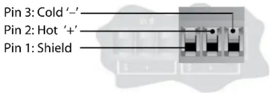
Balanced wiring - The convention for balanced wiring (2-wire plus shield) is:
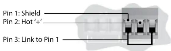
Unbalanced wiring - The convention for unbalanced wiring to the inputs (1-wire plus shield) is:
Control Inputs
Used to connect switches. There are two common (ground) connections, labeled "C" to the left of the eight CONTROL INPUTS, and two software assignable reference voltage outputs, labeled "R" to the right of the eight CONTROL INPUTS.
Relay Contacts
Supports control of a voltage source and load that is AC, or supports control of a voltage source and load that is higher-current DC than is supported by the logic outputs. A normally open circuit or a normally closed circuit is available.
OPTO Output
In addition to the six standard logic outputs, there is an isolated output, which fails safe (open circuit) if the unit becomes faulty.

OPTO Output
Logic Outputs
Used to connect 'tally' indicator LED's or relays. There are six standard LOGIC OUTPUTS which produce 0V or +5V DC via an internal 440 Ohm resistor and one internally connected common (ground) connection C. Each logic output pin can sink up to 60mA.
An LED connected between one output (Anode, A) and common (Cathode, K) will illuminate when the logic output is activated, without requiring any external current limiting resistor. A high sensitivity relay (such as a reed relay) may be driven by connecting four outputs in parallel. This arrangement will develop 4V across a 500-Ohm coil, providing that all four outputs are made logic 1 simultaneously.

Logic Outputs
3.2 Zone Controller Wiring and Installation
Zone Controller Wiring
All Zone Controllers can be wired serially or in parallel. To wire in series, each Zone Controller must have an identification number (ID) chosen using the DIP switches on the side of the controller (see diagram A). A single Zone Controller can be used to control multiple outputs. Conversely, multiple Zone Controllers can be used to control a single zone (for example, a ZC1 and a ZC3 controlling volume and source in a single zone respectively). In every case, each Zone Controller is given a unique ID.
To wire the Zone Controllers in parallel, a ZC-BOB must be used. Each Zone Controller must have a unique identification or number chosen using the DIP switches on the side of the controller (see diagram A). To wire in parallel, each controller must be wired into a port of the ZC-BOB with a connecting wire going to the SC device (see diagram C).
| ZC ID (1-6) ZC ID (7-12) DIP Switch Setting | ||
| 1 | 7 |  |
| 2 | 8 | ON |
| 3 | 9 | ON |
| 4 10 | ON | |
| 5 11 | ON | |
| 6 12 | ON | |
To set up the Zone Controllers, the System Architect GUI must be used. Open the GUI and click on Card Configuration within the Hardware Configuration section of the Tools menu. In this window, Zone Controllers are assigned to ZC Inputs 1-12. The input numbers on the left side of the window correspond to the ID number set using the DIP switches on the individual Zone Controllers. To select ID#2 for example, simply flip the 2 switch into the on position. ID 1-6 are connected to the top ZC input on the rear panel and ID 7-12 are connected to the bottom input. To create ID 7-12, add 6 to the ID # selected on the back of the ZC. For example, to get an ID# of 10, connect to the bottom ZC Input (7-12) and set the ID# to 4.
Zone Controller Installation
The installation of the Zone Controllers MUST be accomplished with the use of cable which is rated VW-1 or higher. Common NEC designations which meet this rating include: CMP, CMR, CMG, CM and CMX.
ZC-1 - The ZC-1 is a programmable zone controller that allows input or output volume level control from a wall panel.
ZC-2 - The ZC-2 is a programmable zone controller that allows input or output volume level and mute control from a wall panel.
ZC-3 - The ZC-3 allows wall panel routing and Actions selection for the SC devices.
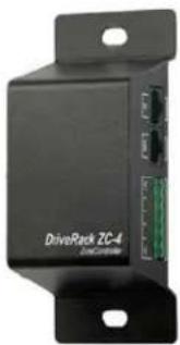
ZC-4 - The ZC-4 provides contact closure routing and Actions selection for room combining or fire safety applications.
ZC-Fire - The ZC-Fire is the interface to generic fire alarm relays. When fire alarm activates, the general purpose relay can typically be programmed to close if normally open or vices-versa. The ZC-fire interface unit monitors the state of the relay (n.o. or n.c.) and upon the state of change, notifies the SC 32/64, which then mutes its outputs.
ZC-6 - The ZC-6 is a push-button up and down input or output volume controller.
ZC-7 - The ZC-7 allows Actions selection for the SC devices.
ZC-8 - The ZC-8 is used for a combination of input or output volume up/down, and four position source/program select.
ZC-9 - The ZC-9 allows wall panel routing and Actions selection for the SC devices.
ZC-BOB - The ZC-BOB allows parallel or home run cabling of the Zone Controllers.
Diagram A

Diagram B

Diagram C

Cable Specification: EIA/TIA 568A Standard (pin to pin) 24 AWG wire

other
RJ-45 (8-Position) | | RJ-45 (8-Position) | Value | |---|---|---| | 1 | White/Green | 1 -VREF | | 2 | Green | 2 -Dip 1 | | 3 | White/Orange | 3 -Dip 2 | | 4 | Blue | 4 -Dip 3 | | 5 | White/Blue | 5 -Dip 4 | | 6 | Orange | 6 -Dip 5 | | 7 | White/Brown | 7 -Dip 6 | | 8 | Brown | 8 -GND |Diagram A
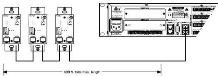
Diagram B
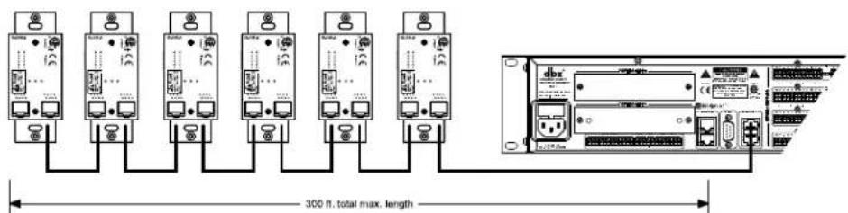
Diagram C

natural_image
Black DriveRack ZC-4 electronic device with ports and connectors (no visible text or symbols on body)ZC-4 wiring diagram.
This Diagram shows all 16 possible combinations for the ZC-4 controller when used as a binary Scene selector
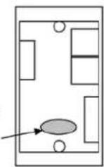
The P2 Jumper must be removed for use with the SC 32 / 64.

Binary 0

Binary 1

Binary 2
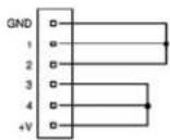
Binary 3

Binary 4

Binary 5

Binary 6
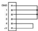
Binary 7
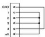
Binary 8

Binary 9

Binary 10

Binary 11

Binary 12

Binary 13

Binary 14
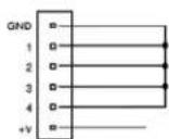
Binary 15
Section 4 - Technical Specifications
FRONT PANEL INDICATORS
Per channel: 48V (yellow), CLIP (red), SIGNAL (green)
Per 8 channel bank: IN (green), OUT (amber), D-IN (blue), D-OUT (yellow), SYNC (green)
Other: 16x2 LCD display, PAGE button (green), SELECT button (green), CLIP (red),
LINK/ACT (green), RS-232 (green), POWER (green)
ANALOG INPUTS
Connectors: Phoenix/Combicon, 3.5mm pitch
Channels: Eight per card
Line/Mic Inputs: Nominal gain 0 dB
Electronically switchable to +6, +12, +18, +24, +30, +36, +42, +48 dB
Type: Electronically balanced, RF Filtered
Input Impedance: 3.5 kΩ
Maximum Input Level: +20 dBu
Noise Floor: -92 dBu "A" weighted
-90 dBu unweighted, 20 Hz - 20 kHz
Dynamic Range: 113 dB "A" weighted, 20 Hz – 20 kHz
110 dB unweighted, 20 Hz - 20 kHz
CMRR: > 40 dB typical, >50 dB at 1 kHz
EIN: < -119 dBu unweighted, 20 Hz – 20 kHz, 150 Ω source impedance
Phantom Power: +48 VDC selectable per input
A/D Latency: 12/Fs
ANALOG OUTPUTS
Connectors: Phoenix/Combicon, 3.5mm pitch
Channels: Eight per card
Type: Electronically balanced, RF Filtered
Impedance: 44Ω
Maximum Output Level: +20 dBu
Noise Floor: -92 dBu "A" weighted
-89 dBu unweighted, 20 Hz - 20 kHz
Dynamic Range: 112 dB "A" weighted
109 dB unweighted, 20 Hz - 20 kHz
D/A Latency: 10.4/Fs
SYSTEM PERFORMANCE
Dynamic Range: 110 dB "A" weighted
107 dB unweighted, 20 Hz to 20 kHz
Frequency Response: 20 Hz - 20 kHz, +0/-0.5 dB
THD+N: 0.0045% 0 dBu input, 1 kHz, 0 dB input gain
0.0065% 0 dBu input, 20 Hz - 20 kHz, 0 dB input gain
Inter-channel crosstalk: > 90 dB typically, 20 Hz - 20 kHz
Internal Processing: 32 bit floating point
Internal Sample Rate: 48 kHz
Latency: 1.82 msec analog input to analog output
2.25 msec analog input to analog output with a mono mid-mixer
CONTROL INPUTS
Connector: Phoenix/Combicon, 3.5mm pitch
Number: 8
Control Voltage Input: 0 to 4.5 VDC
Control Line Impedance: 4.7 kΩ to +5 VDC
Number: 2 connectors with 6 channels per connector for a total of 12 inputs
Useage: For use with dbx ZC wall controllers
LOGIC OUTPUTS
Connector: Phoenix/Combicon, 3.5mm pitch
Number: 6
Logic Output Voltage: 0 or +5 V unloaded
Logic Output Impedance: 440 Ω
Logic Output Current: 10 mA source, 60 mA sink
RELAY CONTACT CLOSURE
Connector: Phoenix/Combicon, 3.5mm pitch
Contacts: Common (C), Normally Open (NO), Normally Closed (NC)
Contact Rated Load: 0.3A at 125VAC, 1A at 30VDC
WATCHDOG OUTPUT
Connector: Phoenix/Combicon, 3.5mm pitch
Type: Opto-isolated
Output Current: 14 mA max
Withstanding Voltage: 80 V max (off)
Series Impedance: 220 Ω isolated
MISCELLANEOUS
Power Requirements: 100 V to 240 VAC, 50/60 Hz
75 Watts for SC32, 120 Watts for SC64
BTU Rating: 256 BTUs maximum for SC 32, 409 BTUs maximum for SC 64
Dimensions: 3.5" tall x 19" wide x 15" deep
Weight: SC 32: 15.7 pounds (with all audio cards installed)
SC 64: 18.9 pounds (with all audio cards installed)
dbx ^® incorporates high quality mechanical fans in some products. All mechanical fans have a limited life expectancy. We recommend annual inspection of fans for dust occlusion and excessive noise. Fan assemblies should be replaced after six to ten years of use. Environmental factors such as elevated temperature, dust, and smoke can adversely affect fan life. Systems exposed to these conditions should be inspected more frequently. Fan replacement can be performed either at the factory or by an experienced technician in the field. Please contact dbx Technical Support for more information on purchasing replacement parts or product service.
dbx has a policy of continued product improvement and accordingly reserves the right to change features and specifications without prior notice.

8760 South Sandy Parkway • Sandy, Utah 84070
Phone: (801) 568-7660 • Fax (801) 568-7662
Int'l Fax: (801) 568-7583
Questions or comments?
Contact us at www.dbxpro.com
Printed in the USA
18-0616-D

- Digital Matrix Processors
- IMPORTANT SAFETY INFORMATION
- SAFETY INSTRUCTIONS
- WARNING FOR YOUR PROTECTION READ THE FOLLOWING:
- ELECTROMAGNETIC COMPATIBILITY
- U.K. MAINS PLUG WARNING
- DECLARATION OF CONFORMITY
- Section 1 - Introduction ...... 1
- Section 2 - Getting Started......4
- Section 3 - Wiring......8
- Section 4 - Technical Specifications......15
- Section 1 - Introduction
- Defining the SC 32 / SC 64
- Service Contact Info
- Warranty
- Section 2 - Getting Started
- Front Panel
- FRONT PANEL LED DISPLAY
- PAGE SELECT BUTTONS
- RS-232 LED
- CLIP LED
- LINK/ACT LED
- POWER LED
- CARD POSITION LABELS - I/O CARD TYPE INDICATION LEDS
- CARD POSITION LABELS - CLIP LED
- CARD POSITION LABELS - SYNC LED
- CARD POSITION LABELS - PHANTOM POWER LED
- CARD POSITION LABELS - SIGNAL LED
- Rear Panel
- OPTION SLOTS
- POWER CONNECTOR
- FUSE
- CONTROL INPUTS
- RELAY
- OPTO
- LOGIC OUTPUTS
- ETHERNET CONNECTORS
- RS-232 PORT
- ZC PORTS
- AUDIO CONNECTOR
- I/O CARD TYPE INDICATION
- Section 3 - Wiring
- SC 32 and SC 64 Wiring
- Audio Cable Wiring
- Audio Input and Output wiring convention
- Relay Contacts
- OPTO Output
- Zone Controller Wiring and Installation
- Zone Controller Wiring
- Zone Controller Installation
- ZC-4 wiring diagram.
- Section 4 - Technical Specifications
- FRONT PANEL INDICATORS
- ANALOG INPUTS
- ANALOG OUTPUTS
- SYSTEM PERFORMANCE
- RELAY CONTACT CLOSURE
- WATCHDOG OUTPUT
- MISCELLANEOUS
Brand : DBX
Model : SC 64
Category : Processeur audio professionnel