
VPX-1401 - Commutateur audiovisuel AMX - Free user manual and instructions
Find the device manual for free VPX-1401 AMX in PDF.


| Product Type | Video Processor / Switcher |
| Dimensions (H x W x D) | 1.75 x 17.5 x 12 inches (rack-mountable, 1U) |
| Weight | Approx. 8.5 lbs (3.9 kg) |
| Power Supply | 100-240 VAC, 50/60 Hz, 60W max |
| Video Inputs | 4x HDMI, 2x DisplayPort |
| Video Outputs | 2x HDMI, 1x VGA/Component |
| Max Resolution | 4K UHD (3840x2160) at 60Hz |
| Audio Support | Embedded HDMI audio, stereo analog out |
| Control Interface | RS-232, Ethernet (ICSLAN), IR, USB |
| Supported Protocols | AMX NetLinx, Crestron, Extron, IP control |
| Scaling | Built-in video scaling and format conversion |
| Picture-in-Picture | Multi-window display with PIP/POP support |
| Seamless Switching | Fast frame-accurate switching with <1 frame delay |
| EDID Management | Internal EDID emulation and programming |
| Maintenance | Firmware upgrade via USB or network, replaceable fan module |
| Cleaning | Wipe with dry cloth; avoid liquid cleaners |
| Safety | UL/CE compliant, internal fuse, overcurrent protection |
| Spare Parts | Power supply, fan, control boards available from AMX |
| Warranty | 3 years limited warranty |
Frequently Asked Questions - VPX-1401 AMX
User questions about VPX-1401 AMX
0 question about this device. Answer the ones you know or ask your own.
Ask a new question about this device
Download the instructions for your Commutateur audiovisuel in PDF format for free! Find your manual VPX-1401 - AMX and take your electronic device back in hand. On this page are published all the documents necessary for the use of your device. VPX-1401 by AMX.
USER MANUAL VPX-1401 AMX
IMPORTANT SAFETY INSTRUCTIONS
- READ these instructions.
- KEEP these instructions.
- HEED all warnings.
- FOLLOW all instructions.
- DO NOT use this apparatus near water.
- CLEAN ONLY with dry cloth.
- DO NOT block any ventilation openings. Install in accordance with the manufacturer's instructions.
- DO NOT install near any heat sources such as radiators, heat registers, stoves, or other apparatus (including amplifiers) that produce heat.
- DO NOT defeat the safety purpose of the polarized or grounding type plug. A polarized plug has two blades with one wider than the other. A grounding type plug has two blades and a third grounding prong. The wider blade or the third prong are provided for your safety. If the provided plug does not fit into your outlet, consult an electrician for replacement of the obsolete outlet.
- PROTECT the power cord from being walked on or pinched, particularly at plugs, convenience receptacles, and the point where they exit from the apparatus.
- ONLY USE attachments/accessories specified by the manufacturer.
- USE ONLY with a cart, stand, tripod, bracket, or table specified by the manufacturer, or sold with the apparatus. When a cart is used, use caution when moving the cart/apparatus combination to avoid injury from tip-over.
- UNPLUG this apparatus during lightning storms or when unused for long periods of time.
- REFER all servicing to qualified service personnel. Servicing is required when the apparatus has been damaged in any way, such as power-supply cord or plug is damaged, liquid has been spilled or objects have fallen into the apparatus, the apparatus has been exposed to rain or moisture, does not operate normally, or has been dropped.
- DO NOT expose this apparatus to dripping or splashing and ensure that no objects filled with liquids, such as vases, are placed on the apparatus.
- To completely disconnect this apparatus from the AC Mains, disconnect the power supply cord plug from the AC receptacle.
- Where the mains plug or an appliance coupler is used as the disconnect device, the disconnect device shall remain readily operable.
- DO NOT overload wall outlets or extension cords beyond their rated capacity as this can cause electric shock or fire.

The exclamation point, within an equilateral triangle, is intended to alert the user to the presence of important operating and maintenance (servicing) instructions in the literature accompanying the product.

The lightning flash with arrowhead symbol within an equilateral triangle is intended to alert the user to the presence of uninsulated "dangerous voltage" within the product's enclosure that may be of sufficient magnitude to constitute a risk of electrical shock to persons.

ESD Warning: The icon to the left indicates text regarding potential danger associated with the discharge of static electricity from an outside source (such as human hands) into an integrated circuit, often resulting in damage to the circuit.

WARNING: To reduce the risk of fire or electrical shock, do not expose this apparatus to rain or moisture.
WARNING: No naked flame sources - such as candles - should be placed on the product.
WARNING: Equipment shall be connected to a MAINS socket outlet with a protective earthing connection.
WARNING: To reduce the risk of electric shock, grounding of the center pin of this plug must be maintained.
COPYRIGHT NOTICE
AMX© 2018, all rights reserved. No part of this publication may be reproduced, stored in a retrieval system, or transmitted, in any form or by any means, electronic, mechanical, photocopying, recording, or otherwise, without the prior written permission of AMX. Copyright protection claimed extends to AMX hardware and software and includes all forms and matters copyrightable material and information now allowed by statutory or judicial law or herein after granted, including without limitation, material generated from the software programs which are displayed on the screen such as icons, screen display looks, etc. Reproduction or disassembly of embodied computer programs or algorithms is expressly prohibited.
LIABILITY NOTICE
No patent liability is assumed with respect to the use of information contained herein. While every precaution has been taken in the preparation of this publication, AMX assumes no responsibility for error or omissions. No liability is assumed for damages resulting from the use of the information contained herein. Further, this publication and features described herein are subject to change without notice.
AMX WARRANTY AND RETURN POLICY
The AMX Warranty and Return Policy and related documents can be viewed/downloaded at www.amx.com.
ESD WARNING

To avoid ESD (Electrostatic Discharge) damage to sensitive components, make sure you are properly grounded before touching any internal materials.
When working with any equipment manufactured with electronic devices, proper ESD grounding procedures must be followed to make sure people, products, and tools are as free of static charges as possible. Grounding straps, conductive smocks, and conductive work mats are specifically designed for this purpose. These items should not be manufactured locally, since they are generally composed of highly resistive conductive materials to safely drain static discharges, with-out increasing an electrocution risk in the event of an accident.
Anyone performing field maintenance on AMX equipment should use an appropriate ESD field service kit complete with at least a dissipative work mat with a ground cord and a UL listed adjustable wrist strap with another ground cord.

CAUTION
RISK OF ELECTRIC SHOCK DO NOT OPEN

WARNING: Do Not Open! Risk of Electrical Shock. Voltages in this equipment are hazardous to life. No user-serviceable parts inside. Refer all servicing to qualified service personnel.
Place the equipment near a main power supply outlet and make sure that you can easily access the power breaker switch.
WARNING: This product is intended to be operated ONLY from the voltages listed on the back panel or the recommended, or included, power supply of the product. Operation from other voltages other than those indicated may cause irreversible damage to the product and void the products warranty. The use of AC Plug Adapters is cautioned because it can allow the product to be plugged into voltages in which the product was not designed to operate. If the product is equipped with a detachable power cord, use only the type provided with your product or by your local distributor and/or retailer. If you are unsure of the correct operational voltage, please contact your local distributor and/or retailer.
FCC AND CANADA EMC COMPLIANCE INFORMATION:
This device complies with part 15 of the FCC Rules.
Operation is subject to the following two conditions:
(1) This device may not cause harmful interference, and (2) this device must accept any interference received, including interference that may cause undesired operation.
NOTE: This equipment has been tested and found to comply with the limits for a Class A digital device, pursuant to part 15 of the FCC Rules. These limits are designed to provide reasonable protection against harmful interference in a commercial environment. This equipment generates, uses and can radiate radio frequency energy and, if not installed and used in accordance with the instructions, may cause harmful interference to radio communications.
However, there is no guarantee that interference will not occur in a particular installation. If this equipment does cause harmful interference to radio or television reception, which can be determined by turning the equipment off and on, the user is encouraged to try to correct the interference by one or more of the following measures:
• Reorient or relocate the receiving antenna.
- Increase the separation between the equipment and receiver.
- Connect the equipment into an outlet on a circuit different from that to which the receiver is connected.
- Consult the dealer or an experienced radio/TV technician for help.
Approved under the verification provision of FCC Part 15 as a Class A Digital
Device. Caution
Changes or modifications not expressly approved by the manufacturer could void the user's authority to operate this device. CAN ICES-3 (B)/NMB-3(B)
EU COMPLIANCE INFORMATION:
Eligible to bear the CE mark; Conforms to European Union Low Voltage Directive 2006/95/EC; European Union EMC Directive 2004/108/EC; European Union Restriction of Hazardous Substances Recast (RoHS2) Directive 2011/65/EU; European Union WEEE (recast) Directive 2012/19/EU; European Union Radio and Telecommunications Terminal Equipment (R&TTE) Directive 1999/5/EC
WEEE NOTICE:

This appliance is labeled in accordance with European Directive 2012/19/EU concerning waste of electrical and electronic equipment (WEEE). This label indicates that this product should not be disposed of with household waste. It should be deposited at an appropriate facility to enable recovery and recycling.
Table of Contents
IMPORTANT SAFETY INSTRUCTIONS 2
Overview 6
Features......6
Package Contents....6
Specifications 7
Transmission Distance 9
Panel Description.... 10
Front Panel Description 10
Rear Panel Description.... 15
Pinout Information 15
RS232&IR 15
Audio IN/OUT 15
Installation and Wiring....16
Installation 16
Wiring 16
OSD....18
Input Source Switching....19
Auto Switching 19
Manual Switching 19
IR Operation....20
Control the Source....20
RS232 Operation 21
NetLinx Control 22
Device Number and Ports 22
Send command to control a device 23
Telnet Control 23
Launch TelnetWindow 23
Web UI Control.... 22
Web UI Control 23
Header Bar....23
Navigation Bar.... 24
Auto Switch.... 24
Key Lock.... 25
HDCP 25
EDID 25
Display.... 26
Audio....26
Resolution.... 26
Logo 27
Network....28
System.... 29
Firmware Upgrade....32
Before Starting 32
Transferring KIT Files.... 32
Troubleshooting 34
APICommandSet....35
NetLinx Commands.... 35
Telnet/SSH Commands 44
Overview
VPX-1401 is an advanced presentation switcher, allowing switching among four inputs and distribution to two outputs. It offers one VGA input with one balanced analog audio embedded, three HDMI inputs, one HDMI output to a local display, plus one balanced de-embedded analog audio output and one HDBaseT mirrored output to a remote display via a Cat X cable.
The VPX-1401 has one built-in scaler which supports up to 4K@60Hz 4:4:4 8bit. The video stream goes through the scaler first before distributing to two outputs. The scaler output can be set to fixed resolution or auto scaling. When set to auto scaling, the scaler analyzes the EDIDs of two connected displays and outputs optimum resolution for both displays.
The VPX-1401 can be set to auto switching or manual switching. The VPX-1401 can be controlled by front panel buttons, LAN control with NetLinx Studio, Telnet API and Web GUI.
Powered by HDBT 2.0 and DSC (Display Stream Compression), the VPX-1401 can transmit 4K@60Hz 4:4:4 8bit video up to 80m / 262 ft via a Shielded Cat 6a/7 cable, with USB 2.0 (Host), bidirectional RS232 and IR pass-through. HDBaseT output also features PoE (PSE) to power an HDBT receiver.
The VPX-1401 simplifies integration and installation of a small presentation system for classrooms and small offices, providing localized presentation switching support over long distances.
Features
• Provides one VGA input with balanced embedded audio, three HDMI inputs, one HDMI and HDBT mirrored outputs
- HDMI inputs, HDMI and HDBT outputs support up to 4K@60Hz 4:4:4 8bit and HDCP 2.2; VGA input supports up to 1920 x 1200@60Hz.
• Built-in scaler supports up to 4K@60Hz 4:4:4 8bit
• Supports one-way PoE to power a remote HDBT receiver
• HDBT transmits 4K@60 4:4:4 signals up to 80m/262 ft, 1080P signal up to 100m/328ft via a shielded Cat6a/7 cable.
• Transmits USB 2.0, bi-directional RS232 and IR signal over HDBT.
• Balanced de-embedded analog audio output with volume control.
• Auto-switching to the latest connected source input by detecting input signal status.
- Fast switching.
- Able to turn on/off connected displays automatically by detecting input signal status with its built-in CEC controller.
• Selection buttons on the front panel for local control and contact closures for remote keypad control.
• Supports LAN control through NetLinx Studio, Telnet API and WEB UI.
Package Contents
• 1 x VPX-1401
• 1 x DC 12V Power Adapter with US, UK and EU AC Power Cords
• 4x Phoenix Male Connector (3.5mm, 5 Pins)
• 1x Phoenix Male Connector (3.5mm, 6 Pins)
• 2 x Mounting Bracket (with Screws)
Specifications
| Technical | |
| Input | 1 x VGA; 3 x HDMI |
| Input Signal Type | HDMI with 4K@60Hz YUV 444, HDCP 2.2VGA |
| Input Resolution Supported | 1280 x 1024 @ 75 Hz1152 x 870 @ 75 Hz1024 x 768 @ 60 Hz, 70 Hz, 75 Hz, 87 Hz832 x 624 @ 75 Hz800 x 600 @ 56 Hz, 60 Hz, 72 Hz, 75 Hz720 x 400 @ 70 Hz, 88 Hz640 x 480 @ 60 Hz, 67 Hz, 72 Hz, 75 HzCEA Video Information Code (VIC) Formats:VIC = 1, 640 x 480p 59.94/60 Hz 4:3VIC = 2, 720 x 480p 59.94/60 Hz 4:3VIC = 3, 720 x 480p 59.94/60 Hz 16:9VIC = 4, 1280 x 720p 59.94/60 Hz 16:9VIC = 5, 1920 x 1080i 59.94/60 Hz 16:9VIC = 6, 720(1440) x 480i 59.94/60 Hz 4:3VIC = 7, 720(1440) x 480i 59.94/60 Hz 16:9VIC = 14, 1440 x 480p 59.94/60 Hz 4:3VIC = 15, 1440 x 480p 59.94/60 Hz 16:9VIC = 16, Native 1920 x 1080p 59.94/60 Hz 16:9VIC = 17, 720 x 576p 50 Hz 4:3VIC = 18, 720 x 576p 50 Hz 16:9VIC = 19, 1280 x 720p 50 Hz 16:1280 x 1024 @ 75 Hz1152 x 870 @ 75 Hz1024 x 768 @ 60 Hz, 70 Hz, 75 Hz, 87 Hz832 x 624 @ 75 Hz800 x 600 @ 56 Hz, 60 Hz, 72 Hz, 75 Hz 720 x 400 @ 70 Hz, 88 Hz640 x 480 @ 60 Hz, 67 Hz, 72 Hz, 75 HzCEA Video Information Code (VIC) Formats:VIC = 1, 640 x 480p 59.94/60 Hz 4:3VIC = 2, 720 x 480 p 59.94/60 Hz 4:3VIC = 3, 720 x 480p 59.94/60 Hz 16:9VIC = 4, 1280 x 720p 59.94/60 Hz 16:9VIC = 5, 1920 x 1080i 59.94/ 60 Hz 16:9VIC = 6, 720(1440) x 480i 59.94/60 Hz 4:3VIC = 7, 720(1440) x 480i 59.94/60 Hz 16:9VIC = 14, 1440 x 480p 59 .94 / 60 Hz 4 :3VIC = 15, 1440 x 480p 59.94/60 Hz 16:9VIC = 16, Native 1920 x 1080p 59.94/60 Hz 16:9VIC = 17, 720 x 576p 50 Hz 4 :3VIC = 18, 720 x 576p 50 Hz 16:9VIC = 19, 1280 x 720p 50 Hz 16:9VIC = 20, 1920 x 1080i 50 Hz 16:9VIC = 21, 720(1440) x 576i 50 Hz 4 :3VIC = 22, 720(1440) x 576i 50 Hz 16:9VIC = 29, 1440 x 576p 50 Hz 4 :3VIC = 30, 1440 x 576p 50 Hz 16:9VIC = 31, 1920 x 1080p 50 Hz 16:9VIC = 32, 1920 x 1080p 23.97/24 Hz 16:9 |
| Technical (cont.) | |
| VIC = 33, 1920 x 1080p 25 Hz 16:9VIC = 34, 1920 x 1080p 29.97/30 Hz 16:9VIC = 39, 1920 x 1080i 50 Hz 16:9VIC = 41, 1280 x 720p 100 Hz 16:9VIC = 42, 720 x 576p 100 Hz 4:3VIC = 43, 720 x 576p 100 Hz 16:9VIC = 44, 720(1440) x 576i 100 Hz 4:3VIC = 45, 720(1440) x 576i 100 Hz 16:9VIC = 47, 1280 x 720p 119.88/120 Hz 16:9VIC = 48, 720 x 480p 119.88/120 Hz 4:3VIC = 49, 720 x 480p 119.88/120 Hz 16:9800x600 8 , 1024x768 8 , 1280x720 8 , 1280x768 8 , 1280x800 8 , 1280x960 8 , 1280x1024 8 , 1360x768 8 , 1366x768 8 , 1440x900 8 , 1600x900 8 , 1600x1200 8 , 1680x1050 8 , 1920x1080 8 , 1920x1200 8 , 2560x1440 8 , 2560x1600 8 , 3840x2160P 2,3,5,8 , 4096x2160P 2,3,5,8 1 = at 23.98 Hz, 2 = at 24 Hz, 3 = at 25 Hz,4 = at 29.97 Hz, 5 = at 30 Hz, 6 = at 50 Hz,7 = at 59.94 Hz, 8 = 60 Hz | |
| Maximum Pixel Clock | 600MHz |
| Output | 1 x HDMI, 1 x HDBaseT |
| Output Signal Type | HDMI with 4K@60Hz YUV 444, HDCP 2.2 |
| Output Resolution Supported | VESA:800x600 8 , 1024x768 8 , 1280x768 8 , 1280x800 8 , 1280x960 8 , 1280x1024 8 , 1360x768 8 , 1366x768 8 , 1440x900 8 , 1600x900 8 , 1600x1200 8 , 1600x1050 8 , 1920x1200 8 , 3840x2160 2,3,5,8 , 4096x2160 2,3,5,8 and Auto ScalingSMPTE:1280x720P 6,8 , 1920x1080P 6,8 1 = at 23.98 Hz, 2 = at 24 Hz, 3 = at 25 Hz, 4 = at 29.97 Hz, 5 = at 30 Hz, 6 = at 50 Hz, 7 = at 59.94 Hz, 8 = at 60 Hz |
| Control Method | • Auto switching• Front panel buttons• Contact closures• LAN (Telnet API, WEB UI)• NetLinx control |
| Audio | |
| Audio Input | 1 x Balanced Analog Audio Inputs: 5-pin Phoenix Connector |
| Audio Output | 1 x Balanced Analog Audio Output: 5-pin Phoenix Connector |
| Audio Format Supported | PCM 2.0 |
| General | |
| Operating Temperature | 0°C to 50°C (32°F to 122°F) |
| Storage Temperature | -10°C to 60°C (14°F to 140°F) |
| Humidity | 5% to 85%, non-condensing |
| ESD Protection | Human-body Model:±10kV (Air-gap discharge)/±5kV (Contact discharge) |
| Power Supply | DC 12V 5A |
| Power Consumption (Max) | 42W |
| Device Dimension (W x H x D) | 240mm x 30mm x 200.2mm/9.45" x 1.18" x 7.88" |
| Product Weight | 1.35kg/2.97lb |
| Certification | CE, FCC, ETL, PSE, RCM |
Transmission Distance
Note: Straight-through category cable wired to T568B standard is recommended.
| Cable Type | Cable Type | Cable Type |
| Shielded Cat 6a/7 | 100m/328 ft | 1080P@60Hz |
| 80m/262 ft | 4K@60 4:4:4 | |
| HDMI | Input/Output: 15m/50ft | 1080P@60Hz |
| Input: 5m/16ftOutput: 10m/33ft | 4K@60Hz 4:2:0 | |
| Input/Output: 5m/16ft | 4K@60Hz 4:4:4 |
Panel Description
Front Panel Description

| No. | Name | Description |
| 1 | VGA IN 1 | Connect to a VGA source. |
| 2 | AUDIO IN 1 | Connect to an audio device for audio input, embedded with the VGA source. |
| 3 | HDMI IN (2-4) | Connect to HDMI sources. |
| 4 | INPUT SELECT | INPUT Selection button:Press to manually select a source as the current source input. The button function can be enabled through command control or WEB UI on NetLinx.1: VGA IN 12-4: HDMI IN 2-4LED: LED is located on the left of the selection button. When the button function is enabled, pressing an input selection button will light the LED Green. |
| 5 | POWER LED(Green) | On: VPX-1401 is powered on.Off: VPX-1401 is powered off. |
Rear Panel Description
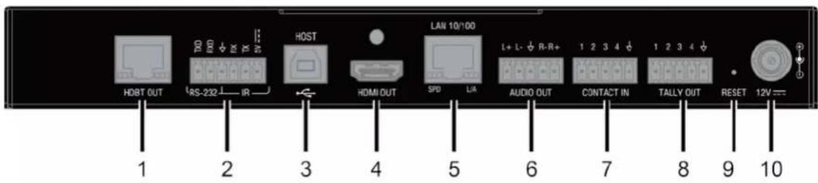
| No. | Name | Description |
| 1 | HDBT OUT | Connect to an HDBT receiver via a Cat 5e/6/7 cable. The port mirrors to HDMI OUT. |
| 2 | RS-232 & IR Connector | Connect to a RS232-enabled device, an IR device. |
| 3 | HOST | Connect to the USB Host device, such as a PC. |
| 4 | HDMI OUT | Connect to an HDMI display. |
| 5 | LAN 10/100 | Connect to an Ethernet device. |
| 6 | AUDIO OUT | Connect to an audio receiver for HDMI audio de-embedding output. |
| 7 | CONTACT IN | Connect pins 1-4 and ↓ to a remote controller for switching among VGA and HDMI inputs.1: Select VGA IN 1.2: Select HDMI IN 2.3: Select HDMI IN 3.4: Select HDMI IN 4.↓: Connect to Ground. |
| 8 | TALLY OUT | Connect pins 1-4 and ↓ to a status display device such as LEDs to indicate which source is currently selected.1: Positive signal means VGA IN is selected.2: Positive signal means HDMI IN 2 is selected.3: Positive signal means HDMI IN 3 is selected.4: Positive signal means HDMI IN 4 is selected.↓: Connect to Ground. |
| 9 | RESET | When VPX-1401 is powered on, use a pointed stylus to hold down the RESET button for three or more seconds, and then release it, it will reboot and restore to its factory defaults. |
| 10 | 12V | Connect to the power adapter provided. |
Pinout Information
The following figures show the pinouts of the phoenix connectors.
RS232&IR
Connects to the RS232 and IR devices with the 6-pole, 3.5mm captive screw connectors.

Audio IN/OUT
Connect to audio device with the 3-pole, 3.5mm captive screw connector.

Installation and Wiring
Warning: Before installation, ensure the device is disconnected from the power source.
Installation
- Attach the installation bracket to the enclosure using the four screws provided.
- The bracket is attached to the enclosure as shown.

natural_image
Line drawing of a server rack with ventilation slots and two connectors (no text or symbols)- Repeat steps 1-2 for the other side of the unit.
- Attach the brackets to a surface or suitable location with user supplied screws.
Wiring
Warning:
• Before wiring, disconnect the power from all devices.
- Connect and disconnect the cables with care.
- Connect the video source
Connect the VGA and HDMI sources (such as PC, Blu-ray player, Apple TV, 4K media player, etc) to the VGA IN and HDMI IN ports of the VPX-1401.
- Connect HDMI OUT
Connect an HDMI display device (such as TV, projector, LED/LCD display) to the HDMI OUT of the VPX-1401.
- Connect AUDIO OUT
Connect an audio receiver (e.g. an amplifier) to the AUDIO OUT of the VPX-1401.
- Connect HDBT OUT
Connect HDBT OUT of VPX-1401 to HDBT IN of an HDBT receiver with a Cat 5e/6/6a/7 cable.
- Connections for additional control options:
• LAN control (NetLinx/Telnet/Web UI): Connect a Local Area Network to the LAN port of the VPX-1401.
- Input source switching control: Connect a keypad and LEDs to CONTACT IN and TALLY OUT ports for input switching and tally indication.
• USB control: Connect a USB host to the VPX-1401, and USB devices to the HDBT receiver for remote KVM control. - RS232 pass-through: Connect an RS232 server device (or client device) to the RS232 port of the VPX-1401, and an RS232 client device (or server device) to the RS232 port of the remote receiver for bidirectional RS232 pass-through.
-
IR pass-through: Connect an IR emitter (or IR receiver) to the IR connector of the VPX-1401, and an IR receiver (or IR emitter) to the IR connector of the HDBT receiver for bi-directional IR pass-through.
-
Connect the power adapter provided to the VPX-1401.
One-way PoE enables the VPX-1401 to power the remote HDBT DSC receiver along a single Cat X cable. No additional power adapter is required at the receiver.
- Power on all attached devices.
When all connections are made and power is ON, check if all LED indicators on the VPX-1401 are normal to ensure the installation is successful. For LED indication, please refer to the Panel Description section.

flowchart
graph TD
    subgraph_ARM["ARM"]
        PC1["PC"] -->|VGA| ARM1["VM1"]
        PC2["PC"] -->|HDMI| ARM2["VM2"]
        PC3["PC"] -->|HDMI| ARM3["VM3"]
        ARM1 -->|L+ L- R+| ARM4["VM4"]
        ARM2 -->|HDMI In 2| ARM5["VM5"]
        ARM3 -->|HDMI In 3| ARM6["VM6"]
        ARM4 -->|L+ L- R+| ARM7["VM7"]
        ARM5 -->|HDMI In 4| ARM8["VM8"]
        ARM6 -->|HDMI Out| ARM9["VM9"]
        ARM7 -->|L+ L- R+| ARM10["VM10"]
        ARM8 -->|L+ L- R+| ARM11["VM11"]
        ARM9 -->|L+ L- R+| ARM12["VM12"]
        ARM10 -->|L+ L- R+| ARM13["VM13"]
        ARM11 -->|L+ L- R+| ARM14["VM14"]
        ARM12 -->|L+ L- R+| ARM15["VM15"]
        ARM13 -->|L+ L- R+| ARM16["VM16"]
        ARM14 -->|L+ L- R+| ARM17["VM17"]
    end

    subgraph_ARM_Rear["ARM"]
        PC2["PC"] -->|HDBT| ARM8
        ARM3 -->|HDBT DSC Receiver| ARM9
        ARM4 -->|HDMI| ARM10
        ARM5 -->|USB| ARM11
        ARM6 -->|USB| ARM12
        ARM7 -->|Audio Out| ARM13
        ARM8 -->|LAN 10/100| ARM14
        ARM9 -->|LAN 10/100| ARM15
        ARM10 -->|LAN Control| ARM16
        ARM11 -->|Ethernet Switch| ARM17
    end

    subgraph_ARM_Rear_Rear["ARM"]
        PC3["PC"] -->|Display| ARM9
        ARM4 -->|Keyboard Mouse| ARM10
        ARM5 -->|Control Signal Feedback| ARM11
        ARM6 -->|Source Selection Status Feedback| ARM12
        ARM7 -->|Control Signal Feedback| ARM13
        ARM8 -->|Control Signal Feedback| ARM14
        ARM9 -->|Control Signal Feedback| ARM15
        ARM10 -->|Control Signal Feedback| ARM16
        ARM11 -->|Control Signal Feedback| ARM17
        ARM12 -->|Control Signal Feedback| ARM18
        ARM13 -->|Control Signal Feedback| ARM19
        ARM14 -->|Control Signal Feedback| ARM20
        ARM15 -->|Control Signal Feedback| ARM21
        ARM16 -->|Control Signal Feedback| ARM22
        ARM17 -->|Control Signal Feedback| ARM23
        ARM18 -->|Control Signal Feedback| ARM24
        ARM19 -->|Control Signal Feedback| ARM25
        ARM20 -->|Control Signal Feedback| ARM26
        ARM21 -->|Control Signal Feedback| ARM27
        ARM22 -->|Control Signal Feedback| ARM28
        ARM23 -->|Control Signal Feedback| ARM29
        ARM24 -->|Control Signal Feedback| ARM30
        ARM25 -->|Control Signal Feedback| ARM31
        ARM26 -->|Control Signal Feedback| ARM32
        ARM27 -->|Control Signal Feedback| ARM33
        ARM28 -->|Control Signal Feedback| ARM34
        ARM29 -->|Control Signal Feedback| ARM35
        ARM30 -->|Control Signal Feedback| ARM36
        ARM31 -->|Control Signal Feedback| ARM37
        ARM32 -->|Control Signal Feedback| ARM38
        ARM33 -->|Control Signal Feedback| ARM39
        ARM34 -->|Control Signal Feedback| ARM40
        ARM35 -->|Control Signal Feedback| ARM41
        ARM36 -->|Control Signal Feedback| ARM42
        ARM37 -->|Control Signal Feedback| ARM43
        ARM38 -->|Control Signal Feedback| ARM44
        ARM39 -->|Control Signal Feedback| ARM45
        ARM40 -->|Control Signal Feedback| ARM46
        ARM41 -->|Control Signal Feedback| ARM47
        ARM42 -->|Control Signal Feedback| ARM48
        ARM43 -->|Control Signal Feedback| ARM49
        ARM44 -->|Control Signal Feedback| ARM50
        ARM45 -->|Control Signal Feedback| ARM51
        ARM46 -->|Control Signal Feedback| ARM52
        ARM47 -->|Control Signal Feedback| ARM53
        ARM48 -->|Control Signal Feedback| ARM54
        ARM49 -->|Control Signal Feedback| ARM55
        ARM50 -->|Control Signal Feedback| ARM56
        ARM51 -->|Control Signal Feedback| ARM57
        ARM52 -->|Control Signal Feedback| ARM58
        ARM53 -->|Control Signal Feedback| ARM59
        ARM54 -->|Control Signal Feedback| ARM60
        ARM55 -->|Control Signal Feedback| ARM61
        ARM56 -->|Control Signal Feedback| ARM62
        ARM57 -->|Control Signal Feedback| ARM63
        ARM58 -->|Control Signal Feedback| ARM64
        ARM59 -->|Control Signal Feedback| ARM65
        ARM60 -->|Control Signal Feedback| ARM66
        ARM61 -->|Control Signal Feedback| ARM67
        ARM62 -->|Control Signal Feedback| ARM68
        ARM63 -->|Control Signal Feedback| ARM69
        ARM64 -->|Control Signal Feedback| ARM70
    end

    subgraph_Front_Panel["ARM"]
        PC1 & PC2 & PC3 & PC4 & PC5 & PC6 & PC7 & PC8 & PC9 & PC10 & PC11 & PC12 & PC13 & PC14 & PC15 & PC16 & PC17 & PC18 & PC19 & PC20 & PC21 & PC22 & PC23 & PC24 & PC25 & PC26 & PC27 & PC28 & PC29 & PC30 & PC31 & PC32 & PC33 & PC34 & PC35 & PC36 & PC37 & PC38 & PC39 & PC40 & PC41 & PC42 & PC43 & PC44 & PC45 & PC46 & PC47 & PC48 & PC49 & PC50 & PC51 & PC52 & PC53 & PC54 & PC55 & PC56 & PC57 & PC58 & PC59 & PC60 & PC61 & PC62 & PC63 & PC64 & PC65 & PC66 & PC67 & PC68 & PC69 & PC70 & PC71 & PC72 & PC73 & PC74 & PC75 & PC76 & PC77 & PC78 & PC79 & PC80 & PC81 & PC82 & PC83 & PC84 & PC85 & PC86 & PC87 & PC88 & PC89 & PC90 & PC91 & PC92 & PC93 & PC94 & PC95 & PC96 & PC97 & PC98 & PC99 |
    end

    subgraph_Rear_Panel["ARM"]
        FrontPanel["Front Panel"] --> FrontPanel_AHX["ARM"]
    end

    subgraph_Rear_Rear["ARM"]
        RearPanel_AHX_                             | FrontPanel_AHX_ |
    end

    note right of FrontPanel_AHX_ to FrontPanel_Rear_Rear_Rear_Rear_Rear_Rear_Rear_Rear_Rear_Rear_Rear_Rear_Rear_Rear_Rear_Rear_Rear_Rear_Rear_Rear_Rear_Rear_Rear_Rear_Rear_Rear_Rear_Rear_Rear_Rear_Rear_Rear_Rear_Rear_Rear_Rear_Rear_Rear_Rear_Rear_Rear_Rear_Rear_Rear_Rear_Rear_Rear_Rear_Rear_Rear_Rears_          AHX_          AHX_DI           AHX_IN_             AHX_IN_             AHX_IN_             AHX_IN_             AHX_IN_             AHX_IN_             AHX_IN_             AHX_IN_             AHX_IN_             AHX_IN_             AHX_IN_             AHX_IN_             AHX_IN_             AHX_IN_             AHX_IN_             AHX_IN_             AHX_IN_             AHX_IN_             AHX_IN_             AHX_IN_             AHX_IN_            AHX_DI          AHX_IN_             AHX_IN_             AHX_IN_             AHX_IN_             AHX_IN_             AHX_IN_             AHX_IN_             AHX_IN_             AHX_IN_             AHX_IN_             AHX_IN_             AHX_IN_             AHX_IN_             AHX_IN_             AHX_IN_             AHX_IN_             AHX_IN_             AHX_IN_             AHX_IN_             AHX_IN_              AHX_DI          AHX_IN_             AHX_IN_             AHX_IN_             AHX_IN_             AHX_IN_             AHX_IN_             AHX_IN_             AHX_IN_             AHX_IN_             AHX_IN_             AHX_IN_             AHX_IN_             AHX_IN_             AHX_IN_             AHX_IN_             AHX_IN_             AHX_IN_             AHX_IN_             AHX_IN_            AHX_DI           AHX_IN           AHX_IN           AHX_IN           AHX_IN           AHX_IN           AHX_IN           AHX_IN           AHX_IN           AHX_IN           AHX_IN           AHX_IN           AHX_IN           AHX_IN           AHX_IN           AHX_IN           AHX_IN           AHX_IN           AHX_IN           AHX_IN           AHX_IN           AHX_IN           AHX_IN           AHX_IN           AHX_IN           AHX_IN           AHX_OUT         / / / / / / / / / / / / / / / / / / / / / / / / / / / / / / / / / / / / / / / / / / / / / / / / / / / / / / / / / / / / / / / / / / / / / / / / / / / / / / / / / / / / / / / / / / / / /
OSD
The VPX-1401 supports OSD (On Screen Display) to display its IP address. Follow these steps to initiate OSD:
- Press and Hold the front panel buttons Input 1 and Input 2 for at least 3 seconds.
- The IP address of the VPX-1401 will display at the upper right of the connected display's screen for about 15s and then disappear.

Input Source Switching
VPX-1401 supports Auto and Manual Switching among the VGA and HDMI inputs.
Auto Switching
- When multiple sources are inserted, and power is ON for all devices, the input will be switched to the active source with the highest priority.
- Priority: VGA IN 1 > HDMI IN 2 > HDMI IN 3 > HDMI IN 4
- When a new source is inserted, the input will be switched to it automatically, following the Last-In-First-Out rule.
- When the currently selected source is removed, the input will first be switched to the most recently selected port. If the port has no active source, the input will be switched to the active source with the highest priority.
Note:
- When in Auto Switching, Input Select buttons do not function. To use input select buttons, disable Auto Switching.
• The Auto Switching function is enabled by default once all devices are powered on.
• You can enable or disenable Auto Switching through command setting or WEB UI on NetLinx.
Manual Switching
If you want to select a specific input port using input selection buttons:
- Disable Auto Switching through command setting or WEB UI on NetLinx.
- Press the appropriate Input Select Button to select a desired input port. When an inactive port is selected, the VPX-1401 will output no signal.

IR Operation
The IR pass-through function allows emote control of the source from the display location or the display from the source location.
Control the Source
To control the source from the display location:
- Connect an IR emitter to IR port of the VPX-1401;
- Connect a broadband IR receiver to the IR IN port of an HDBT receiver.
When the connections are completed, the source can be controlled at the display location through a source remote.

RS232 Operation
The RS232 port of the VPX-1401 can be used for bi-directional RS232 signal pass-through between VPX-1401 and an HDBT receiver. To set up RS232 pass-through:
- Connect an RS232 Server (or Client) Device to the RS232 port of the VPX-1401 with an RS232 cable (See Pinout Information Section for RS232 wiring);
- Connect an RS232 Client (or Server) Device to the RS232 port of an HDBT receiver with an RS232 cable.
- Connect HDBT OUT of the VPX-1401 to HDBT IN of the HDBT receiver with a Cat 5e/6/7 cable.
When the connections are complete, an RS232 signal can be passed through bi-directionally between two RS232 devices.

NetLinx Control
Controlling the VPX-1401 through NetLinx Studio.
Before launching NetLinx Studio, connect the VPX-1401, PC, control system (e.g. NX-3200) to the same network.
Note: IDs and IP addresses in the following illustrations are examples. Check the Online Tree in NetLinx Studio to find the correct addresses for your device.
Device Number and Ports
Each VPX-1401 has its own Device Number (which is assigned when the unit is bound to a Control System) and the following ports.
Port 1: VGA IN 1 (AUDIO IN 1); HDMI OUT; HDBT OUT; AUDIO OUT
Port 2: HDMI IN 2
Port 3: HDMI IN 3
Port 4: HDMI IN 4
Port 5-8: Unused
Port 9: RS-232
Port 10: HOST
Port 11: IR
Port 12-21: Unused
Port 22: CONTACT IN
Port 23: TALLY OUT
In NetLinx Studio's Online Tree, the VPX-1401 module displays its ports.
![System 3 Devices [192.160.20.200] 06000 - NX-3200 Masters (v1.4.06) 05001 - NX-3200 (v1.1.42) Dynamic/Virtual Devices 32001 - NSX Application (v4.4.1.1626) 32002 - VFX-1401 (2.2) Device Number Port - 1 Port - 2 Port - 3 Port - 4 Port - 5 Port - 6 Port - 7 Port - 8 Port - 9 Port - 10 Port - 11 Port - 12 Port - 13 Port - 14 Port - 15 Port - 16 Port - 17 Port - 18 Port - 19 Port - 20 Port - 21 Port - 22 Port - 23 Ports on VFX-1401](/content/2026/05/994125/images/4354e40572c1193c61a9d539c331caf41a13c3fd89ab9bcbc64d67c764e6e3b5.jpg)
Send command to control a device
Click "Diagnostics" on the menu bar, select "Control a Device".

A window will display as follows, type the Device number, Port number, System and command respectively, and click "Send To Device". (For API commands, see the Section API Command Set.)

Telnet Control
Launch Telnet Window
To launch Telnet Window,
- Right click the Device Number in NetLinx Studio's Online Tree, select "TELNET Window" – "Launch TELENT Window via NetLinx Studio" (or "Launch TELENT Window via User Defined Program").
![Netline Studio File Edit View Print Build Diagnostics Debug Tools Settings Window Help Workspace for Systems 3 Devices [156.160.20.20] 10000 - MX-200 Metizo (v1.4.8) 10001 - MX-300 (v1.4.8) Dynamic/Virtual Devices 32001 - HRC ExpLinear WINNE - 798-1401 Port - 1 Port - 2 Port - 3 Port - 4 Port - 5 Port - 6 Port - 7 Port - 8 Port - 9 Port - 10 Port - 11 Port - 12 Port - 13 Port - 14 Port - 15 Port - 16 Port - 17 Port - 18 Port - 19 Port - 20 Port - 21 Port - 22 Port - 23 Port - 24 Port - 25 Port - 26 Port - 27 Port - 28 Port - 29 Port - 30 Port - 31 Port - 32 Port - 33 Port - 34 Port - 35 Port - 36 Port - 37 Port - 38 Port - 39 Port - 40 Port - 41 Port - 42 Port - 43 Port - 44 Port - 45 Port - 46 Port - 47 Port - 48 Port - 49 Port - 50 Port - 51 Port - 52 Port - 53 Port - 54 Port - 55 Port - 56 Port - 57 Port - 58 Port - 59 Port - 60 Port - 61 Port - 62 Port - 63 Port - 64 Port - 65 Port - 66 Port - 67 Port - 68 Port - 69 Port - 70 Port - 71 Port - 72 Port - 73 Port - 74 Port - 75 Port - 76 Port - 77 Port - 78 Port - 79 Port - 80 Port - 81 Port - 82 Port - 83 Port - 84 Port - 85 Port - 86 Port - 87 Port - 88 Port - 89 Port - 90 Port - 91 Port - 92 Port - 93 Port - 94 Port - 95 Port - 96 Port - 97 Port - 98 Port - 99 Port - 100 Refresh System Online Tree Refresh Network Online Tree Show Only Port Counts on Refresh Show BOP Systems during Refresh Network Show Device Properties Check Port Status Firmware Transfer... Bulk Firmware Transfers... Online Tree Reporting... Refresh Device Mapping Device Addressing... Network Device Addressing... Network Bind/Unid Device... Send Specify Mode Command Refresh User Manager Web Control Page TELNET Window Expand Tree Expand to Device Level Collapse Tree Preferences... (1) (0) (1) (2) ClipEvent: Online: S2001:16:13 (1) (0) (1) ClipEvent: Online: S2002:17:3 (1) (0) (1) ClipEvent: Online: S2003:18:13 (1) (0) (1) ClipEvent: Online: S2004:19:3 (1) (0) (1) ClipEvent: Online: S2005:20:13 (1) (0) (1) ClipEvent: Online: S2006:22:3 (1) (0) (1) ClipEvent: Online: S2007:23:3 (1) (0) (1) ClipEvent: Online: S2008:24:3 (1) (0) (1) ClipEvent: Online: S2009:25:3 (1) (0) (1) ClipEvent: Online: S2010:26:3 (1) (0) (1) ClipEvent: Online: S2011:27:3 (1) (0) (1) ClipEvent: Online: S2012:28:3 (1) (0) (1) ClipEvent: Online: S2013:29:3 (1) (0) (1) ClipEvent: Online: S2014:30:3 (1) (0) (1) ClipEvent: Online: S2015:31:3 (1) (0) (1) ClipEvent: Online: S2016:32:3 (1) (0) (1) ClipEvent: Online: S2017:33:3 (1) (0) (1) ClipEvent: Online: S2018:34:3 (1) (0) (1) ClipEvent: Online: S2019:35:3 (1) (0) (1) ClipEvent: Online: S2020:36:3 Launch TELNET Window via NetLine Studio Launch TELNET Window via User Defined Program Find All Files / File Transfer Status / Notifications / Default Push Inactie: 192.668.20.20-1.78](/content/2026/05/994125/images/fc5f5ff9e8fed39dae8e55b580bc75246e664a9f8a5a2cb1003613012f3df9f2.jpg)
The Telnet window opens.
![NetLine Studio - 192.168.2011 File Edit View Build Build Diagnostics Debug Tools Settings Window Help Workspace Bar Systems 3 Devices [192.168.20.200] 00000 - WX-1200 Master (v1.4.36) 05001 - WX-1200 (v1.1.42) Dynamic/Virtual Devices 32001 - RXX Application (v4.6.1.1628) SOP - VFX-1401 [1.3] Ports - 1 Ports - 2 Ports - 3 Ports - 4 Ports - 5 Ports - 6 Ports - 7 Ports - 8 Ports - 9 Ports - 10 Ports - 11 Ports - 12 Ports - 13 Ports - 14 Ports - 15 Ports - 16 Ports - 17 Ports - 18 Ports - 19 Ports - 20 Porto 1 4 M Dimler Master(s) Devens Ports Line 17 2018-08-06 (12v06:17): ClpEvent::Online 12002:16:3 Line 18 2018-08-06 (12v06:17): ClpEvent::Online 12002:17:3 Line 19 2018-08-06 (12v06:17): ClpEvent::Online 12002:18:3 Line 20 2018-08-06 (12v06:17): ClpEvent::Online 12002:19:3 Line 21 2018-08-06 (12v06:17): ClpEvent::Online 12002:20:3 Line 22 2018-08-06 (12v06:17): ClpEvent::Online 12002:21:3 Line 23 2018-08-06 (12v06:17): ClpEvent::Online 12002:22:3 Line 24 2018-08-06 (12v06:17): ClpEvent::Online 12002:23:3 Line 25 2018-08-06 (12v06:17): Resending to 32001 count = 4 (latency=4) CldTimeout=4@ DevTimeout=5004A Line 26 2018-08-06 (12v06:17): Resending to 32001 count = 5 (latency=4) CldTimeout=500 DevTimeout=5004A Line 27 2018-08-06 (12v06:17): ConnectionManager got unsolicited Ping responses from device 32002 of system 3 (IP 19) Line 28 2018-08-06 (12v06:17): ConnectionManager got unsolicited Ping responses from device 32002 of system 3 (IP 19) Output Bar Name / Load In Pits / Load B Pits / For Summary Status / Notifications / Diagnostics Ready Win Use Push Inactive 92.168.20.200.1379 Ln 1Cat 1](/content/2026/05/994125/images/982bbbf75a4a944d114beadcc11f750af9fc6998b05bd38f8767d847217d17ba.jpg)
- At the prompt ( > ), type the Telnet command and press Enter.
* Selecting "Launch TELENT Window via User Defined Program", may require enabling Telnet by completing the following:
(1) go to Start/Control Panel/Programs and Features;
(2) on the left, select "Turn Windows features on or off";
(3) select the check-boxes Telnet Client and Telnet Server, and click OK.

Web UI Control
To configure and control the device on the Web, right click the Device Number in the Online Tree Tab, choose "Web Control Page" – "Launch Web Control Page via NetLinx Studio".
![NetLine Studio File Edit View Project Build Diagnostics Debug Tools Settings Window Help Workspace Bar System 3 Devices [192.168.20.200] 00000 - XX-3200 Master (v1.4.06) 05001 - XX-3200 (v1.1.42) Dynamic/Virtual Devices 12001 - HEX Appliance 12002 - VEX-1401 (7) Port - 1 Port - 2 Port - 3 Port - 4 Port - 5 Port - 6 Port - 7 Port - 8 Port - 9 Port - 10 Port - 11 Port - 12 Port - 13 Port - 14 Port - 15 Port - 16 Port - 17 Port - 18 Port - 19 Master(s) Devices Ports 1 4 56 Display Workspace Online Tree Refresh System Online Tree Refresh Network Online Tree Show Only Port Counts on Refresh Show NDP Systems during Refresh Network Show Device Properties Check Port Status Firmware Transfer... Bulk Firmware Transfers... Online Tree Reporting... Refresh Device Mappings Device Addressing... Network Device Addressing... Network Bind/Unbind Device... Send Identify Mode Command Reboot the Master Web Control Page TELNET Window Expand Tree Expand to Device Level Collapse Tree Preferences... Launch Web Control Page via NetLine Studio Launch Web Control Page via Default Browser Find Kit Files Fire Transfer Status Notifications Drag Push-Inactive 192.168.23.200.1319](/content/2026/05/994125/images/27fce0f89724ba4d5d8045392e7f0be08cc6300689419ff5d4c9dab2eb02d0a0.jpg)
Web UI Control
The Web UI designed for the VPX-1401 allows basic controls and advanced settings of the device. The Web UI page can be accessed through NetLinx Studio.
To access the VPX-1401 Web UI:
- Connect your PC and the LAN port of the VPX-1401 to the same local area network.
- In NetLinx Studio's Online Tree, select "Web Control Page" – "Launch Web Control Page via Default Browser" (or select "Launch Web Control Page via NetLinx Studio").
The following page will pop up. Enter the default password "admin" and click "Login".
VPX-1401 Control

The main screen displays as follows.

The Web UI page consists of header bar and navigation bar for basic and advanced settings, including Auto Switch, HDCP, EDID, Display, Resolution, Network, System, etc.
Header Bar
The header bar consists of logo, the following five buttons and version information.

: Refresh button, click to refresh the Web UI to the latest setting.

Factory Default button, click to reset the device to factory default settings.
Steps to reset the device to factory default settings:
- Click "Factory Default" button.
- Click "OK" to proceed.

A successful reset will restore all the device settings to their factory defaults and the device will reboot automatically. Allow at least 2 minutes for the reboot to complete.

bot button, click to reboot the device.
Steps to reboot the device:
- Click "Reboot" button.
- Click "OK" to proceed. Then the device will reboot immediately.


Update status button, click to view the device's firmware upgrade status.

Logout button, click to logout from the Web UI.

Displays the device's firmware version information.
Navigation Bar
The navigation bar includes the following tabs: AutoSwitch, Key Lock, HDCP, EDID, Display, Relay, Audio, Resolution, Logo, Network and System.
Auto Switch
Auto Switch allows switching among multiple inputs without using the buttons on the front panel.

• ON: Click to enable Auto Switch (default setting).
• OFF: Click to disable Auto Switch.
Key Lock
Key Lock allows locking of the buttons on the VPX-1401 to prevent accidental or unwanted switching.
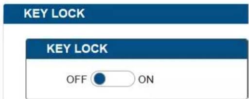
• ON: Click to enable Key Lock.
• OFF: Click to disable Key Lock (default setting).
HDCP
HDCP Support allows enabling or disabling HDCP compatibility of each input and HDMI output.
HDCP SUPPORT
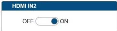
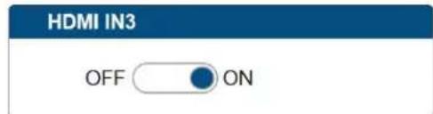


• ON: Click to enable HDCP compatibility for the corresponding input, which will transmit HDCP protected content (default setting).
• OFF: Click to disable HDCP compatibility for the corresponding input, which will transmit non-HDCP protected content.
For HDMI Out:
- FOLLOW: Select to follow the output display's HDCP compatibility for the HDMI Out, which will transmit content with the same HDCP compatibility as that of the output display (default setting).
• HDCP 2.2: Select to transmit HDCP 2.2 protected content to the output display.
• HDCP 1.4: Select to transmit HDCP 1.4 protected content to the output display. - NO HDCP: Select to transmit non-HDCP protected content to the output display. (Note: If "NO HDCP" is selected for HDMI OUT, when the HDCP protected signal is being input, the receiver will output no signal.)
• Apply: Click to make the selection to take effect.
EDID
EDID Support allows configuration of the EDID setting of each input.
Locate the target input port and select specific EDID settings from the drop-down menu, then click "Apply" to perform the setting. The default EDID settings for all HDMI input ports are "Copy EDID from output display".
EDID SUPPORT
VGA
1920x1080@60Hz 2CH (Default)
APPLY
HDMI IN2
Copy from output (Default)
APPLY
HDMI IN3
Copy from output (Default)
APPLY
HDMI IN4
Copy from output (Default)
APPLY
Display
DISPLAY
AUTO DISPLAY CONTROL
OFF

ON
DELAY TIME(1-30 min)
2 min
Auto Display Control allows control of CEC-enabled displays connected to the VPX-1401 through HDMI.
• ON: Click to enable the Auto Display Control.
• OFF: Click to disable the Auto Display Control. (Default setting)
- DELAY TIME (1\~30 min): Click the down arrow to set the time for the display to power off automatically when no signal is present. Example: With the time set to 2 minutes, the output display will be powered off automatically when there is no signal input for 2 minutes.
Note: The time range for Auto Display Control is 1-30 minutes.
Audio
AUDIO
Output Volume:

bar
| Value | |---| | 100 |Min/Max:

□ Mute
• Output Volume: Move the slider to set the output audio volume.
• Min/Max: Move the sliders at the left and right sides of the scale to set the minimum and maximum range of the audio volume.
- Mute: Check (or uncheck) to mute (or unmute) the audio.
Resolution
OUTPUT RESOLUTION
OUTPUT RESOLUTION SETTING
AUTO

MANUAL
1920x1080@60
APPLY
- AUTO: Click to set the output resolution to Auto mode (default setting). The output resolution may vary based on the connected display's native resolution.
- MANUAL: Click to set the output resolution to Manual mode. In Manual mode, click the down arrow to select a specific output resolution as required.
- APPLY: Click to set the output resolution to the desired setting.
Logo

Logo section allows display content configuration for the display screen when there's no signal output to the display.
- BLACK COLOR/LOGO:
1) BLACK: Select to set the display screen as black when there's no signal output to the display.
2) LOGO: Select to set the display to show a logo picture when there's no signal output to the display.
- LOGO TRANSITION:
1) FIX IN CENTER: Select to set the logo picture to be shown in the display screen's center when there's no signal output to the display. (Default setting)
2) DRAG TOP LEFT: Select to set the logo picture to shuttle slowly between the center and the top left of the display screen when there's no signal output to the display.
3) DRAG TOP RIGHT: Select to set the logo picture to shuttle slowly between the center and the top right of the display screen when there's no signal output to the display.
4) DRAG BOTTOM LEFT: Select to set the logo picture to shuttle slowly between the center and the bottom left of the display screen when there's no signal output to the display.
5) DRAG BOTTOM RIGHT: Select to set the logo picture to shuttle slowly between the center and the bottom right of the display screen when there's no signal output to the display.
- Logo Setup
1) CHOOSE FILE: Click to upload a logo file to the switcher from your local computer.
2) SAVE: Click to perform the logo file uploading.
Note:
• The logo file should be in .png format with size not larger than 1280x720, 60KB.
- When the logo is loaded to the device successfully, the device will reboot immediately.
Network
NETWORK
DEVICE IP MODE

DHCP

STATIC
DEVICE IP ADDRESS
192.168.20.101
SUBNET MASK
255.255.255.0
DEFAULT GATEWAY
192.168.20.1
MAC ADDRESS
10:52:50:50:21:0b
IP HOSTNAME
AMX-VPX-1401-50210B
DNS 1
192.168.20.1
DNS 2
0.0.0.0
APPLY
NOTE: LAN MODULE WILL AUTOMATICALLY REBOOT AFTER CHANGING NETWORK SETTING.
Device IP Mode:
- DHCP: When enabled, the IP address of the switcher will be assigned automatically by the connected DHCP server.
- Static: When the switcher fails to obtain or detect an IP address from the network to which it is connected, select "Static" to set up the IP address manually.
• APPLY: Click to set the network setting.
Note: Allow 2-3 minutes for the device's LAN module to reboot and reconnect after the network setting is changed.
System
SYSTEM
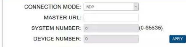
ICSP PARAMETER
LOGIN PASSWORD

TELNET/SSH ACCESS
TELNET ACCOUNT

SSH ACCOUNT

UPLOAD CERTIFICATE

The system section is used to configure the ICSP Parameter, login password, Telnet/SSH account and upload certificate.
- ICSP PARAMETER:
• CONNECTION MODE: includes four options: NDP, Auto IP, URL/TCP, URL/UDP. The default setting is NDP.
• CONTROLLER URL: Input the connected controller's URL.
- SYSTEM NUMBER : Use the Online Tree to determine the system number. By default, it is disabled to be configured.
- DEVICE NUMBER : Use the Online Tree to determine it. By default, it is disabled to be configured.
- LOGIN PASSWORD:
LOGIN PASSWORD: Login Password can be changed. The default Login Password is admin.
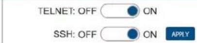
- TELNET/SSH ACCESS
TELNET/SSH ACCESS is used to enable or disable Telnet/SSH capability. The default setting is ON.
Note: Reboot the device for the setting change to take effect.
- TELNET/SSH ACCOUNT
TELNET/SSH ACCOUNT is used to configure the user name and password of the account.
• TELNET ACCOUNT
The default user name and password are null.
- SSH ACCOUNT
The default user name is admin, the default password is password. Note: Reboot the device for the SSH ACCOUNT setting change to take effect.
• APPLY: Click to choose each of the settings.
-
Upload Certificate
-
Password: Enter the password of the certificate uploaded.
- Private Key (.pem): Click "CHOOSE FILE" to browse for the private key in .pem format of the https certificate in your local computer.
- Certificate (.pem): Click "CHOOSE FILE" to browse for the https certificate in .pem format in your local computer.
- Upload: Click to upload the https certificate and its private key to the device.
Note: When certificate upload is completed, the certificate module will reboot automatically.
Firmware Upgrade
The VPX-1401 uses KIT files for firmware upgrade.
Before Starting
- Verify that you have the latest version of NetLinx Studio on your PC.
- Download the latest firmware (KIT) file to your PC. (Place KIT files on a local drive for the fastest throughput.)
-
Verify the following:
a) Verify that an Ethernet/RJ-45 cable is connected from the VPX-1401 to the same network as the control system. b) Verify the VPX-1401 unit is powered ON. -
Launch NetLinx Studio and open the Online Tree.
-
Bind the device to the integrated Controller: select and right-click the VPX-1401; from the context sensitive menu, select Network Bind/Unbind Device (be sure the check box is selected); click OK.
![Bind/Unbind Device Device to Bind/Unbind [00000:00000] VTK-140L v8.6 192.168.20.53 [88.1b:32.89:71:9c] Master Binding (check or uncheck) System IP Address MAC Address [ 2] 192.168.20.200 00:60:9f:9e:2b:98 OK Cancel](/content/2026/05/994125/images/3d9be9483fcbc583e1b28256663d85abfea4bfd2398072e3418378a1d86f6cab.jpg)
Transferring KIT Files
- In NetLinx Studio, choose Tools > Firmware Transfers > Send to NetLinx Device to open the "Send to NetLinx Studio" dialog.

- Click to navigate to the target directory. The selected directory path is displayed in the Location text box. KIT files in the target directory display under FileName.
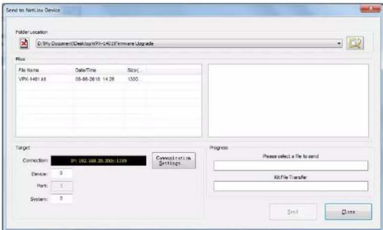
- Select the appropriate KIT file from the File Name list.


- IMPORTANT SAFETY INSTRUCTIONS
- COPYRIGHT NOTICE
- LIABILITY NOTICE
- AMX WARRANTY AND RETURN POLICY
- ESD WARNING
- FCC AND CANADA EMC COMPLIANCE INFORMATION:
- EU COMPLIANCE INFORMATION:
- WEEE NOTICE:
- Table of Contents
- Overview
- Features
- Package Contents
- Transmission Distance
- Panel Description
- Pinout Information
- RS232&IR
- Audio IN/OUT
- Installation and Wiring
- Installation
- Wiring
- Warning:
- OSD
- Input Source Switching
- Auto Switching
- Note:
- Manual Switching
- IR Operation
- Control the Source
- RS232 Operation
- NetLinx Control
- Device Number and Ports
- Send command to control a device
- Telnet Control
- Launch Telnet Window
- Web UI Control
- Header Bar
- Navigation Bar
- Auto Switch
- Key Lock
- HDCP
- HDCP SUPPORT
- For HDMI Out:
- EDID
- EDID SUPPORT
- VGA
- HDMI IN2
- HDMI IN3
- HDMI IN4
- Display
- AUTO DISPLAY CONTROL
- Audio
- Resolution
- OUTPUT RESOLUTION
- OUTPUT RESOLUTION SETTING
- Logo
- Network
- DEVICE IP MODE
- DEVICE IP ADDRESS
- SUBNET MASK
- DEFAULT GATEWAY
- MAC ADDRESS
- IP HOSTNAME
- DNS 1
- DNS 2
- System
- Firmware Upgrade
- Before Starting
- Transferring KIT Files
- Troubleshooting
- API Command Set
- NetLinx Commands
Brand : AMX
Model : VPX-1401
Category : Commutateur audiovisuel