CBS-52H-15 - Coffee maker Fetco - Free user manual and instructions
Find the device manual for free CBS-52H-15 Fetco in PDF.


| Product Type | Coffee Brewer |
| Brand | Fetco |
| Model | CBS-52H-15 |
| Dimensions (W x D x H) | approximately 17.5 x 20.5 x 28 inches |
| Weight | approximately 65 lbs |
| Power Supply | 120 V, 60 Hz, 15 A |
| Brewing Capacity | up to 2.2 gallons per hour |
| Water Tank Material | Stainless steel |
| Heating Element | 1500 W immersion heater |
| Controls | Digital timer and thermostat |
| Brewing Method | Pour-over or automatic drip |
| Safety Features | Automatic shut-off, boil-dry protection |
| Cleaning | Daily rinse and periodic decalcifying |
| Spare Parts | Available: brew basket, carafe, gaskets |
| Repairability | Modular design for easy servicing |
| Warranty | 1 year limited warranty |
Frequently Asked Questions - CBS-52H-15 Fetco
User questions about CBS-52H-15 Fetco
0 question about this device. Answer the ones you know or ask your own.
Ask a new question about this device
Download the instructions for your Coffee maker in PDF format for free! Find your manual CBS-52H-15 - Fetco and take your electronic device back in hand. On this page are published all the documents necessary for the use of your device. CBS-52H-15 by Fetco.
USER MANUAL CBS-52H-15 Fetco
CBS-5000 Series Coffee Brewers
Models:
natural_image
Exterior view of a modern industrial machine (no visible text or symbols)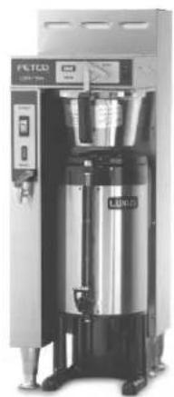
natural_image
Industrial equipment setup with stainless steel and black control panel (no visible text or symbols)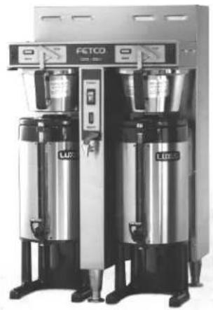
natural_image
Exterior view of a modern industrial water treatment unit with two identical funnels and control panel (no visible text or symbols)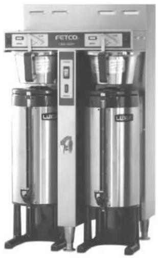
natural_image
Exterior view of two large stainless steel coffee machines (FETCO and LEXA) with control panel and side-mounted buttons (no visible text or symbols on main body)
Driven To Pioneer Innovation™
Table of Contents
| Contact Information | 2 |
| Introduction | 2 |
| Product Description/Features | 2 |
| Specifications | 2 |
| Dimensions & Utility Connections | 4 |
| Installation | 6 |
Operating Procedures 8
Service....9
Brewer Parts 14
Troubleshooting....22
FETCO® and LUXUS® are trademarks or trade names of Food Equipment Technologies Company.
Contact Information
FETCO®
Food Equipment Technologies Company
600 Rose Road
Lake Zurich • IL • 60047-0429 • USA
Internet: www.fetco.com
Phone: (800) 338-2699 (US & Canada)
(847) 719-3000
Fax: (847) 719-3001
Email: sales@fetco.com
techsupport@fetco.com
Introduction
This manual applies only to CBS-5000 Series brewers manufactured with solid state relays (SSR) in the heating circuit. Earlier versions utilized mercury relays for heating. Refer to User's Guide # P004 for mercury relay versions.
The first digit of the serial number can be used to identify the version of a particular unit:
Serial number begins with 6 - SSR version.
Serial number begins with 0 or 1 - mercury relay version.
Product Description/Features
CBS-51H10 - Single 1.0 Gallon Coffee Brewer CBS-51H15 - Single 1.5 Gallon Coffee Brewer
• Thermal, portable, beverage dispensers
- Stainless steel, gourmet size brew baskets
- Brew basket double safety locks
- Open type, leak free dispense system
- Fully automatic, with electronic temperature control
- Two level tank drain system
• Total serviceability from the front
* Can be added at any time.
CBS-52H15 - Twin 1.5 Gallon Coffee Brewer CBS-52H20 - Twin 2.0 Gallon Coffee Brewer
Optional Features:
• Half batch brewing capability*
- Iced tea brewing capability*
• Color stainless steel finish
- Export voltage
• 3.0 liter airpots, with stands,
Note: Throughout this manual, all references to CBS-51H and CBS-52H brewers apply to all models, unless otherwise indicated.
Specifications
Brew Volume: CBS-51H10
Full Batch 1 gal. (3.8 lit.)
Half Batch 12 gal. (1.9 lit.)
CBS-51H15 & 52H15
1 ½ gal. (5.7 lit.)
^3/_4 gal. (2.8 lit.)
CBS-52H20 Temperature:
2 gal. (7.6 lit.)
1 gal. (3.8 lit.)
205°F inside water tank (at sea level)
195^ ± 5^ at sprayhead
Brew Time: CBS-51H10
Full Batch 2 34 - 3 min.
Half Batch 1 12 min.
(Allow an extra 2-4 minutes for coffee to finish dripping)
CBS-51H15 & 52H15
4 - 4 12 min.
2 - 2 14 min.
CBS-52H20
5 12 - 6 min.
2 3/4 - 3 min.
Bypass Range: 0 to 33%
(factory set at 0% unless specified)
(Not available on CBS-51H10)
Coffee Filter Size: CBS-51H10
13" X 5"
CBS-51H15, 52H15, & 52H20
15" X 5 ½ " - standard
13" X 5" - optional half batch
Water Requirements: 20-75 psig
12 gpm (CBS-51H)
1 ¼ gpm (CBS-52H)
Weights and Capacities
| Brewer Model | Weight (empty) | Water tank Capacity & Weight. | Weight (filled) | Dispenser Weight, ea. | Dispenser Filled, ea.. | Total Weight Brewer & Dispensers, Filled | |
| CBS-51H10 | 42 lbs. | 3.0 gal. | 25 lbs. | 67 lbs. | 7.0 lbs. | 15.4 lbs. | 82.4 lbs. |
| CBS-51H15 | 55 lbs. | 3.7 gal. | 31 lbs. | 86 lbs. | 8.5 lbs. | 21 lbs. | 107 lbs. |
| CBS-52H15 | 82 lbs. 7.6 | gal. 63 lbs. | 145 lbs. 8.5 | lbs. 21 lbs. | 187 lbs. | ||
| CBS-52H20 | 87 lbs. | 7.6 gal. | 63 lbs. | 150 lbs. | 10 lbs. | 26.6 lbs. | 203.2 lbs. |
Electrical Configuration and Brewing Efficiency
CBS-51H10
1.0 gallon
| Electrical Heater Config. Code | Voltage Maximum Configuration | Batches per Hour (max 13) | KW | Amp draw | ||||
| Connection | Phase | Wires | Cold Water | Hot Water | ||||
| C50016 | 1 X 1800 watt | 120 | 1 ph. | 2 + ground | 1.9 | 15.8 | 4.5 | 10.3 |
| C50026 | 2 X 1800 watt | 120/208 | 1 ph. | 3 + ground | 3.1 | 13.5 | 6.7 | 13.0 |
| 120/220 | 1 ph. | 3 + ground | 3.4 | 14.7 | 7.8 | 13.0 | ||
| 120/240 | 1 ph. | 3 + ground | 4.1 | 15.5 | 8.9 | 13.0 | ||
| Electrical Config. Code | Heater Configuration | Voltage Connection | Phase | Wires | KW | Maximum Amp draw | Batches per Hour (max 11) | |
| Cold Water | Hot Water | |||||||
| C51016 | 1 X 1800 watt | 120 | 1 ph. | 2 + ground | 1.9 | 15.5 | 3.0 | 6.8 |
| C51026 | 1 X 3000 watt | 120/208 | 1 ph. | 3 + ground | 2.3 | 11.2 | 3.7 | 8.6 |
| 120/220 | 1 ph. | 3 + ground | 2.6 | 11.8 | 4.3 | 10.0 | ||
| 120/240 | 1 ph. | 3 + ground | 3.1 | 12.9 | 5.0 | 11.0 | ||
| C51036 | 1 X 4000 watt | 120/208 | 1 ph. | 3 + ground | 3.1 | 14.8 | 5.0 | 11.0 |
| 120/220 | 1 ph. | 3 + ground | 3.5 | 15.7 | 5.8 | 11.0 | ||
| 120/240 | 1 ph. | 3 + ground | 4.1 | 17.1 | 6.6 | 11.0 | ||
| C51046 | 2 X 3000 watt | 120/208 | 1 ph. | 3 + ground | 4.6 | 22.0 | 7.4 | 11.0 |
| 120/220 | 1 ph. | 3 + ground | 5.1 | 23.3 | 8.6 | 11.0 | ||
| 120/240 | 1 ph. | 3 + ground | 6.1 | 25.4 | 9.9 | 11.0 | ||
| C51056 | 2 X 4000 watt | 120/208* | 1 ph. | 3 + ground | 6.1 | 29.3 | 9.9 | 11.0 |
*(-5) version is rated for 208 volts maximum
CBS-52H15
1.5 gallons
| Electrical Config. Code | Heater Configuration | Voltage Connection | Phase | Wires | KW | Maximum Amp draw | Batches per Hour (max 22) | |
| Cold Water | Hot Water | |||||||
| C52016 | 2 X 3000 watt | 120/208 | 1 ph. | 3 + ground | 4.6 | 22.0 | 7.4 | 17.2 |
| 120/220 | 1 ph. | 3 + ground | 5.1 | 23.3 | 8.6 | 19.9 | ||
| 120/240 | 1 ph. | 3 + ground | 6.1 | 25.4 | 9.9 | 22.0 | ||
| C52026 | 2 X 4000 watt | 120/208 | 1 ph. | 3 + ground | 6.1 | 29.3 | 9.9 | 22.0 |
| 120/220 | 1 ph. | 3 + ground | 6.8 | 30.9 | 11.5 | 22.0 | ||
| 120/240 | 1 ph. | 3 + ground | 8.1 | 33.8 | 13.2 | 22.0 | ||
| C52036 | 3 X 3000 watt | 120/208 | 3 ph. | 4 + ground | 7.0 | 19.4 | 11.2 | 22.0 |
| 120/220 | 3 ph. | 4 + ground | 7.8 | 20.5 | 12.9 | 22.0 | ||
| 120/240 | 3 ph. | 4 + ground | 9.1 | 22.4 | 14.9 | 22.0 | ||
| C52046 | 3 X 4000 watt | 120/208 | 3 ph. | 4 + ground | 9.2 | 25.6 | 14.9 | 22.0 |
| 120/220 | 3 ph. | 4 + ground | 10.3 | 27.1 | 17.3 | 22.0 | ||
| 120/240 | 3 ph. | 4 + ground | 12.1 | 29.6 | 19.8 | 22.0 | ||
| C52186 | 3 X 4000 watt | 480 | 3 ph. | 3 + ground | 12.1 | 14.8 | 19.8 | 22.0 |
| C52986 | STEAM maximum steam demand: 40 lbs./hour steam pressure: 10 – 15 PSI | |||||||
CBS-52H20
2.0 gallons
| Electrical Config. Code | Heater Configuration | Voltage Connection | Phase | Wires | KW | Maximum Amp draw | Batches per Hour (max 18) | |
| Cold Water | Hot Water | |||||||
| C53016 | 2 X 3000 watt | 120/208 | 1 ph. | 3 + ground | 4.6 | 22.0 | 5.6 | 12.9 |
| 120/220 | 1 ph. | 3 + ground | 5.1 | 23.3 | 6.5 | 14.9 | ||
| 120/240 | 1 ph. | 3 + ground | 6.1 | 25.4 | 7.4 | 17.2 | ||
| C53026 | 2 X 4000 watt | 120/208 | 1 ph. | 3 + ground | 6.1 | 29.3 | 7.4 | 17.2 |
| 120/220 | 1 ph. | 3 + ground | 6.8 | 30.9 | 8.6 | 18.0 | ||
| 120/240 | 1 ph. | 3 + ground | 8.1 | 33.8 | 9.9 | 18.0 | ||
| C53036 | 3 X 3000 watt | 120/208 | 3 ph. | 4 + ground | 7.0 | 19.4 | 8.4 | 18.0 |
| 120/220 | 3 ph. | 4 + ground | 7.8 | 20.5 | 9.7 | 18.0 | ||
| 120/240 | 3 ph. | 4 + ground | 9.1 | 22.4 | 11.2 | 18.0 | ||
| C53046 | 3 X 4000 watt | 120/208 | 3 ph. | 4 + ground | 9.2 | 25.6 | 11.2 | 18.0 |
| 120/220 | 3 ph. | 4 + ground | 10.3 | 27.1 | 12.9 | 18.0 | ||
| 120/240 | 3 ph. | 4 + ground | 12.1 | 29.6 | 14.9 | 18.0 | ||
| C53186 | 3 X 4000 watt | 480 | 3 ph. | 3 + ground | 12.1 | 14.8 | 19.8 | 22.0 |
| C53986 | STEAM maximum steam demand: 40 lbs./hour steam pressure: 10 – 15 PSI | |||||||
Dimensions & Utility Connections
CBS-51H10
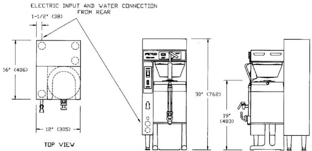
CBS-51H15
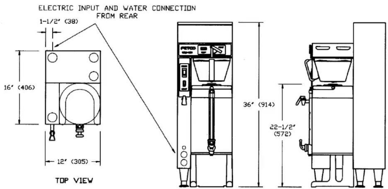
CBS-52H15
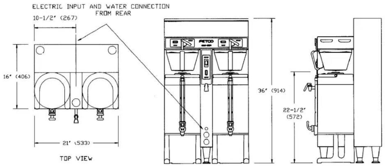
CBS-52H20
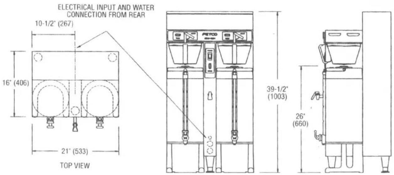
Installation
(For Qualified Service Technicians Only)
Keys To A Successful Installation
If not installed correctly by qualified personnel, the brewer may not operate properly and damage may result.
Damages resulting from improper installation are not covered by the warranty.
Here are the key points to consider before installation:
Electrical:
All FETCO brewers require NEUTRAL. Ground is not an acceptable substitute. Installation without neutral may cause damage to the electronic components.
The power connection to L2 on the terminal block must be at least 105 volts. Less than 105 volts will cause erratic behavior from the brewer.
The power switch has a built-in circuit breaker. To reset it, turn to the "off" position, and then back to the "on" position.
❖ The electrical drawing for the brewer is located on the inside of the lower cover.
Plumbing:
This equipment is to be installed to comply with the applicable federal, state, or local plumbing codes.
The water line must be flushed thoroughly prior to connecting it to the brewer to prevent debris from contaminating the machine.
✿ Verify that the water line will provide at least 12 gallons per minute for the CBS-51H, and 114 gallons per minute for the CBS-52H before connecting it to the brewer.
General:
Utilize only qualified beverage equipment service technicians for installation. A Service Company Directory may be found on our web site, http://www.fetco.com.
Installation Instructions
Brewer Setup
- Review the Dimensions for the unit you are installing. Verify that the brewer will fit in the space intended for it, and that the counter or table will support the total weight of the brewer and dispensers when filled.
-
The brewer's legs are shipped inside the brew baskets. Remove the brew basket(s) and the coffee dispenser(s). Place the brewer on its back and screw in the legs.
-
Place the brewer on the counter or stand.
-
When the brewer is in position, level it front to back and side to side by adjusting the legs.
-
Remove the lower cover to access the water and electrical connections. Knock-outs are provided in the back and base of the brewer body for the connections.

Warning: Legs are to be adjusted for leveling the brewer only. Do not use for height adjustment or extend them higher than necessary.
Water Connection
- Water inlet is a 3/8 inch male flare fitting.
- The brewer can be connected to a cold or hot water line. Cold water is preferred for best coffee flavor, but hot water will allow for faster recovery times.
- Install a water shut off valve near the brewer to facilitate service. If an in-line water filter is used, it should be installed after the water shut off valve and in a position to facilitate filter replacement.
- Flush the water supply line and filter before connecting it to the brewer.
- Verify that the water line will provide at least 12 gallons per minute for the CBS-51H, and 1 14 gallons per minute for the CBS-52H, and that the water pressure is between 20 and 75 psig.
- Use a wrench on the factory fitting when connecting the incoming water line. This will reduce stress on the internal connections and reduce the possibility of leaks developing after the install has been completed.
Electrical Connection
- Verify that the actual voltage at the electrical service connection is compatible with the specifications on the brewer's serial number label. Make sure the electrical service includes neutral.
- The temperature and water tank fill level are pre-set at the factory. There is no need to turn off the heaters during the installation process. The control board disables the heaters until the tank is full of water. The heating process will start automatically when the tank has filled.
- Only 120VAC powered units are shipped from the factory with power cords and plugs attached. For other voltages, a terminal block is provided for connecting the incoming power wires. Consult local codes to determine if a cord and plug can be installed, or if the unit must be hard wired.
- A fused disconnect switch or circuit breaker on the incoming power line must be conveniently located near the brewer, and its location and markings known to the operators.
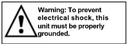
- The body of the brewer must be grounded to a suitable building ground. A ground lug is provided in the brewer next to the power terminal block. Use only 10 gauge copper wire for grounding.
- Electrical connections must be secured in-place within the unit to meet national and local standards.
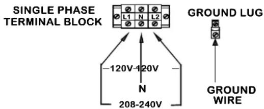
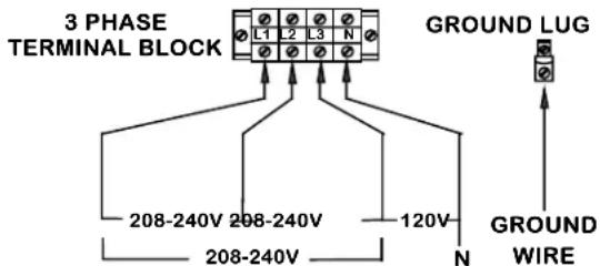
Electrical Configurations – US & Canada
- Finally, connect the incoming power wires to the terminal block in accordance with applicable codes.
Final Setup
- Turn on the incoming water supply line and inspect both inside and outside of the brewer for leaks in all fittings and tubes
- Turn on the incoming power.
- Turn on the brewer's main power switch.
- Within 6 seconds, the hot water tank will begin filling until the probe at the top of the tank senses the water.
- The control board will disable the heaters until the tank is full.
- The brewer will be ready for operation as soon as the ready light comes on to signify that the water tank is up to temperature. The time required to reach brewing temperature will vary according to the electrical configuration ordered.
- Review the Operating Instructions. Brew one full batch (water only) on each side to confirm proper fill levels. The brewer is factory set with water only (no coffee) to dispense the correct amount of water.
- Re-attach the covers after one final inspection for leaks. Look closely in the top of the brewer at the dispense fittings during this inspection.
Operator Training
Review the operating procedures with whoever will be using the brewer. Pay particular attention to the following areas:
- Always pre-heat the dispensers before the first use of each day by filling them half way with hot water, and letting them stand for at least 15 minutes.
- Don't remove the brew basket until it has stopped dripping.
- Make sure the dispenser is empty before brewing into it.
- Show how to attach covers, close, and or secure the thermal dispensers for transporting.
- Show the location and operation of the water shut off valve as well as the circuit breaker for the brewer.
- Steam from the tank will form condensation in the vent tubes. This condensation will drip into and then out of the brew baskets. 1/4 cup discharging overnight is possible. Place an appropriate container under each brew basket when not in use.
- We recommend leaving the power to the brewer on overnight. The water tank is well insulated and will use very little electricity to keep the tank hot. Leaving the brewer in the on position will also avoid delays at the beginning of shifts for the brewer to reach operating temperature.
Operating Procedures
1. Turn brewer on/off switch (E) to the on position
- The power switch will illuminate to indicate that the brewer has power and is operating.
- When the ready light (F) illuminates, the brewer is fully up to temperature. The amount of time required to gain full operating temperature will vary depending on the electrical configuration that was ordered, and the temperature of the incoming water.
2. Pre-heat the dispensers.
This step is very important to the overall success of the brewing operation. FETCO avoids the damaging affects of heat on fresh brewed coffee by using highly insulated dispensers. The dispenser must be pre-heated with hot water from the brewer. This preheating process ensures that the coffee in the first brew starts out hot. Significant heat loss will occur when brewing coffee into a cold dispenser. Preheating is not required for subsequent brews unless the dispenser remains empty for an extended period of time and has cooled down.
- Slide the empty brew basket(s) (D) into their rails and put the empty dispenser(s) in position under the basket for preheating. Select the half batch mode, (A) if you have this option.
- When the ready light illuminates, start a brew cycle by rotating the brew lever (B) to the brew position. This starts clean hot water flowing into the brew basket and then into the dispenser.
- Stop the cycle when each dispenser is approximately 1/2 full by moving the brew lever to the off position. This interrupts the brew cycle and resets the brewer.
- Let the dispensers stand 10-15 minutes, or until use, to allow the heat from the water to be absorbed by the dispensers.
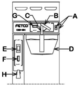
Legend:
A-Full/half batch switch
B-Brew lever
C-Safety bar
D-Brew basket
E-On/off switch
F-Ready light
G-Brew light
H-Hot water faucet
3. Remove the brew baskets from the brewer when you are certain that the flow of hot water has stopped from the bottom of the basket.
- H model brewers will have a safety bar (C) in front of the brew basket to make removing the brew basket a 2-handed operation. This was done to help draw attention to the basket so the operator will notice any residual hot water or coffee.
- Place a paper filter in each basket to be used. Pour into the paper filter the appropriate amount of pre-measured, ground coffee. The amount of coffee used will depend on your personal tastes and the recommendation of your roaster.
- Slide the brew basket back into the rails on the brewer. Insure the latch is outside of the basket.
4. Carefully drain any coffee or preheating water from the dispensers through the faucets before starting a coffee brewing cycle.
- Overflowing of the dispensers may result if the dispensers are not completely empty when the brew cycle begins. Verify by opening the faucet over an appropriate container or drain. The last several cups cannot be seen in the sight gauge tube.
- CAUTION: both the coffee or water may still be hot enough to cause burns, so be careful when draining the dispensers
5. Place the thermal dispenser(s) in position under the brew baskets.
- Ensure that the brew funnel is in place, the dispenser is empty, and the faucet is closed. If you are using TPD-1.5 dispensers, also make sure the vent cap on the sight gauge is open.
- The twist lock cover (TPD-1.5 dispensers) is for transporting the dispenser only. It must be removed before placing the dispenser under the brew basket.
6. Start the brew cycle in the same manner used to start the water used to preheat the dispensers.
- It will not be necessary to interrupt the cycle while brewing coffee. The brewer will return to the stopped and ready status automatically.
- It is normal for the ready light to go out after the start of the brew cycle. On twin brewers, there is enough hot water in the brewer to support a second brew, even if the ready light is off. After brewing on both sides, you must wait for the ready light to come back on.
- The electrical configuration and the electrical power connected to the brewer will determine how long before the ready light comes back on for the next brew.
(Continued on next page)
CAUTION
- Do not remove the brew basket immediately after the brew cycle has finished. Wait until dripping from the bottom of the brew basket has stopped. Carefully remove the brew basket while inspecting the inside of the basket for hot coffee that may have been trapped or has not finished draining.
Service
Warranty
All FETCO brewers come with a limited warranty. All warranty service must be pre-authorized by calling the FETCO Service Department at (800) 338-2699.
Principles of Operation
Fill System
The fill system consists of a liquid level control board, a water level probe at the top of the tank, a fill valve, and a fill tube. As the water rises and touches the probe, continuity is established between the probe tip and the tank body, and the fill valve closes.
When water is dispensed, the water level drops below the probe. After a 5 second delay, the fill valve opens until the water touches the probe again.
The 5 second delay, and the speed that water refills the tank during brewing, results in many short bursts of water. The sound made by these repetitive bursts will let you know the fill system is functioning normally.
The fill system is designed to protect the heaters during both the installation and a loss of the water supply. During initial installation, or whenever the power switch is turned on, voltage will not be supplied to the thermostat until the tank fills and water touches the water level probe.
During operation, when water is dispensed and the water level drops below the probe, a fill signal is sent to the fill valve. If the probe senses no water after 40 seconds, the voltage to the thermostat and the heaters is removed.
Water enters the tank through the fill tube. A hole is drilled in the upper portion of the fill tube to prevent water from being siphoned from the tank. The fill tube extends to the bottom area of the tank. This introduces cold incoming water directly to the heaters and away from the dispense assembly.
The water tank can be drained through a valve located inside the lower compartment of the brewer.
Temperature System:
The temperature system consists of an electronic thermostat, a temperature probe, solid state relays (SSR), and heating elements, and is enabled by the liquid level control board. (See the previous section - Fill Circuit.)
When the water level probe is in contact with water, power is delivered to the thermostat through the liquid level control board. If the temperature probe senses that the water is not hot enough, the thermostat energizes the heating elements through the solid state relay (SSR), the water is heated, and the ready light goes off.
Once the water temperature reaches the set point, the thermostat disengages power to the heaters and the ready light illuminates.
The thermostat is adjusted to 205^ F ± 2^ at the factory. (Slightly lower for high altitude installations.)
Timing System:
The timing system consist of the timer and the dispense latch assembly.
When the brew handle is rotated from the stop to the brew position, it pushes the plunger in the latch coil and closes the micro switch, and the timer starts the timed cycle. It also starts the hot water flowing.
The timer energizes the dispense latch coil, which acts as a magnet, to hold the brew handle in the brew position. It also lights the brew light. The coil remains energized throughout the brew cycle timed sequence.
When the timer finishes its cycle, it removes voltage from the latch coil. The latch coil then releases the brew handle, a spring returns it to the stop position, and the flow of water stops. This return opens the micro switch, stopping voltage from going to the timer. The brew light and the timer are disabled, and wait for the brew handle to engage the next brew cycle.
Dispense System:
The dispense system is completely mechanical. It is one of the areas that makes FETCO's brewer truly unique. (See the illustration in this section.)
When you rotate the brew lever down to brew, the end of the dispense tube is submerged in the hot water tank. It is held in the brew position by the magnetic action of the dispense latch coil.
The brew water travels down the dispense tube to the sprayhead assembly. The flow disc above the spray cutter controls the rate of flow over the coffee. The standard hole in the flow disc is .240", except for the CBS-51H10, which is .219". Other flow discs are available for special situations like high levels of by-pass.
The sprayhead can be assembled incorrectly during cleaning. Refer to the cleaning label on the brewer for proper assembly. The flow disc has the flange down, flat side up. The six triangle spray cutter has the flange up. The eight hole spray cutter used in place of the triangle cutter goes bumps down.
A bypass valve and tube are connected to the sprayhead. This valve directs brew water around the outside edge of the filter paper. The by-pass valve is shipped in the closed position from the factory. Each time the valve is adjusted, the brew volume is affected. Adjustment of the by-pass valve is for flavor only.
When the timer circuit releases the brew latch, the dispense tube pops back above the hot water level. The remaining brew water drains from the dispense system leaving it free of standing water. Steam escaping from the brew tank through this tube inhibits the formation of lime in the brew system.
The dispense system is clean & semi dry for all but the brief time required for the brew cycle. This eliminates any chance of lime build-up affecting the brew cycle.
It is very easy to dislodge the dispense tube seals while servicing the dispense system. If you see it leaking profusely, remove the nut and dispense tube. Reset the seal fully into the recess and carefully insert the dispense tube. Then secure the locknut before you back the tube into position. (See detailed instructions on page 10.)
Mechanical Illustration - Dispense System
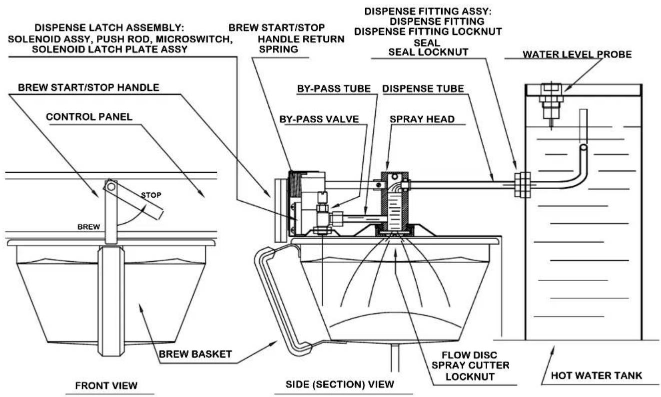
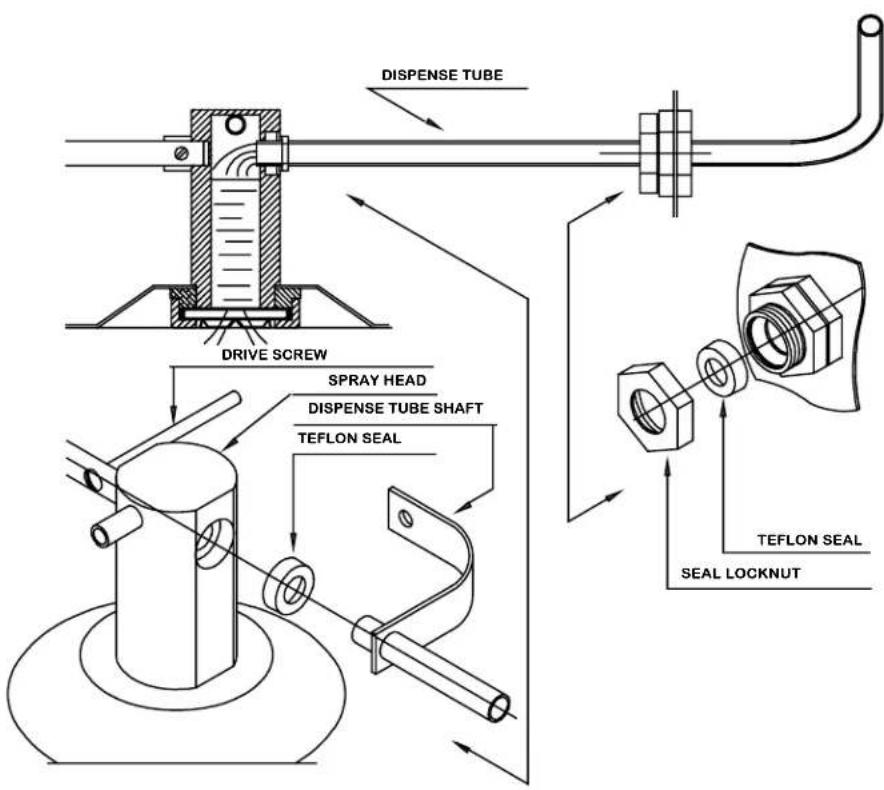
To remove the dispense tube:
-
Unscrew seal locknut and release the drive screw from dispense tube shaft.
-
Turn the dispense tube slightly back and forth, while pushing the tube into the hot water tank until it is free from the sprayhead.
Pull the dispense tube out of the tank. Remember the tube is bent inside the tank. The seal will come out with the tube.
To install the dispense tube:
-
Clean any lime build up off the tube and then slide the seal off. Push the seal carefully into its chamber in the fitting. (spring towards the hot water tank.)
-
Place the seal locknut onto the tube and slide the tube into the seal. Tighten the seal locknut.
-
Work the tube back into the sprayhead seal.
-
Join the dispense tube shaft and the brew handle shaft with the drive screw.
Adjustments
Thermostat Adjustment:
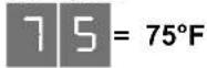
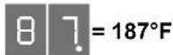
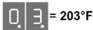
During normal operation, the digital readout displays the last two digits of the actual water temperature. When the adjustment tool is turned, the readout begins flashing to indicate the set point, not the actual temperature. After the tool is released, the readout stops flashing and displays the actual temperature again.
A red LED lights when the power to the thermostat is on. A yellow LED lights when the thermostat is calling for heat.
To adjust, turn the adjustment tool. If no adjustment tool is present, a small flat-head screwdriver may be used. The display will flash, indicating that the display is showing the set point, not the actual temperature.
The dots below the numbers indicate the temp range.
0 dots – less than 100^ F
1 dot - between 100^ and 200^
2 dots - over 200° F
Examples:
Timer Adjustment:
The timer has two independent settings, with three dials for each setting. The first dial in each group sets 100 second increments, the second dial sets 10 second increments, and the third dial sets 1 second increments.
A red LED lights when the power to the timer is on. A yellow LED lights when the timer is running.
A small flat head screwdriver is required to adjust the dials.
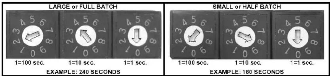
part # K034, digital timer, 100-120 VAC
part # K036, digital timer, 200-240 VAC (export versions only)
Water Level Control Board
The board features a jumper to adjust its' sensitivity for reverse osmosis or other types of ultra-pure water.
The default jumper setting is LO (50K ohms) for normal water. If the brewer tank overfills because of ultrapure water, the jumper should be set to HI (100K ohms).
A red LED lights when the power to the board is on.
A green LED lights when the water level probe detects that the tank is full.
A yellow LED lights when the FILL circuit is energized.
A second yellow LED lights when the HEAT circuit is energized.
Bypass Adjustment: (Not available on CBS-51H10)
The purpose of the bypass valve is to allow a portion of the brewing water to flow between the brew basket and the wire insert, directly into the server, without coming in contact with the coffee grounds. The bypass can be adjusted from 0% to 33% of the total brewing water. Dual brewers (CBS-52H), have separate bypass valves on each side. Unless requested at the time of order, all brewers are shipped with the bypass valves closed (0%). Adjusting the bypass always changes the total brew volume, so the timer setting must always be checked and adjusted.
To adjust the bypass:
- Remove the brewer's upper cover.
- The bypass valve is located above the brew basket, to the right and to the front, as you are facing it.
- Remove the brew basket.
- Place a container under the spray head, and a separate container under the bypass hole.
- Turn the bypass valve clockwise to decrease, and counter-clockwise to increase the bypass amount. A good starting point would be one full turn for each 5% change.
- Brew a full cycle and measure the amount of water in both containers.
- The ratio of the bypass water to the total in both containers is the bypass percentage. example: 12 gal. bypass + 1 gal. from spray head = 1 12 gal. total. Bypass = 33.3%.
• Several adjustments may be necessary until the desired results are achieved.
Brewer Parts
Parts drawings for models CBS-51H10 and CBS-52H20 were not available at the time of publication. Listed below are the major components for these models.
| CBS-51H10 | PART # | DESCRIPTION | |
| K033 DIGITAL THERM | MOSTAT KIT, 100-120VAC | ||
| K035 DIGITAL THERM | MOSTAT KIT, 200-240VAC (EXPORT) | EXPORT ONLY | |
| K034 DIGITAL TIMER | KIT, 100-120VAC | ||
| K036 DIGITAL TIMER | KIT, 200-240VAC | EXPORT ONLY | |
| 108034 ASSEMBLY, BOARD, WATER LEVEL, CONTROL, 100-120 VAC, 50-100K ohm | |||
| 108035 ASSEMBLY, BOARD, WATER LEVEL, CONTROL, 200-240 VAC, 50-100K ohm | EXPORT ONLY | ||
| 57006 VALVE, S-53 1 | 20VAC | ||
| 57017 VALVE, S-53 2 | 40VAC | EXPORT ONLY | |
| 52077 BREAKER,CIRCUIT 120VAC ROCKER SWITCH 6 AMP | |||
| 52076 BREAKER,CIRCUIT 220VAC ROCKER SWITCH 6 AMP | EXPORT ONLY | ||
| 102008 ASSEMBLY, DISPENSE SOLENOID LATCH, 120 VAC | |||
| 102039 ASSEMBLY, DISPENSE SOLENOID LATCH, 220 VAC | EXPORT ONLY | ||
| 58027 LAMP, READY | INDICATOR, GREEN 120VAC | ||
| 58006 LAMP, READY | INDICATOR, GREEN 220VAC | EXPORT ONLY | |
| 58026 LAMP, BREW | 120VAC | ||
| 58004 LAMP, BREW | 220VAC | EXPORT ONLY | |
| 71021 FAUCET HPSC-BR-8 REGULAR HANDLE, (COMPLETE FAUCET) | |||
| 71039 FAUCET, UPPER ASSY. (SUBCOMPONENT OF #71021) | |||
| 71003 FAUCET SEAT CUP (SUBCOMPONENT OF #71021) | |||
| 24008 SEAL, DISPENSE TUBE, 7/16"DIA | |||
| 002049 WELDMENT DISPENSER TUBE | |||
| 85004 SPRING, BREW HANDLE RETURN | |||
| 05017 SPRAY CUTTER FLOW DISK, 0.219 DIA. HOLE | |||
| 05001 SPRAY CUTTER, 6 HOLE | |||
| 31015 LOCKNUT, SPRAY CUTTER | |||
| 102360 SWITCH, SLIDE, FULL/HALF BATCH SELECTOR, W/ HARNESS | |||
| 101010 ASSEMBLY, BREW BASKET, 13 X 5 | |||
| 09001 BREW BASKET WIRE INSERT, 13 X 5 (SUBCOMPONENT OF 101010) | |||
| CBS-52H20 | PART # | DESCRIPTION | |
| K033 DIGITAL THERMOSTAT KIT, 100-120VAC | |||
| K035 DIGITAL THERMOSTAT KIT, 200-240VAC (EXPORT) | EXPORT ONLY | ||
| K034 DIGITAL TIMER KIT, 100-120VAC | |||
| K036 DIGITAL TIMER KIT, 200-240VAC | EXPORT ONLY | ||
| 108034 ASSEMBLY, BOARD, WATER LEVEL, CONTROL, 100-120 VAC, 50-100K ohm | |||
| 108035 ASSEMBLY, BOARD, WATER LEVEL, CONTROL, 200-240 VAC, 50-100K ohm | EXPORT ONLY | ||
| 102323 VALVE, S-45 120VAC | |||
| 57022 VALVE, S-45 240VAC | EXPORT ONLY | ||
| 52077 BREAKER,CIRCUIT 120VAC ROCKER SWITCH 6 AMP | |||
| 52076 BREAKER,CIRCUIT 220VAC ROCKER SWITCH 6 AMP | EXPORT ONLY | ||
| 102008 ASSEMBLY, DISPENSE SOLENOID LATCH, 120 VAC | |||
| 102039 ASSEMBLY, DISPENSE SOLENOID LATCH, 220 VAC | EXPORT ONLY | ||
| 58027 LAMP, READY INDICATOR, GREEN 120VAC | |||
| 58006 LAMP, READY INDICATOR, GREEN 220VAC | EXPORT ONLY | ||
| 58026 LAMP, BREW 120VAC | |||
| 58004 LAMP, BREW 220VAC | EXPORT ONLY | ||
| 71021 FAUCET HPSC-BR-8 REGULAR HANDLE, (COMPLETE FAUCET) | |||
| 71039 FAUCET, UPPER ASSY. (SUBCOMPONENT OF #71021) | |||
| 71003 FAUCET SEAT CUP (SUBCOMPONENT OF #71021) | |||
| 24008 SEAL, DISPENSE TUBE, 7/16"DIA | |||
| 002033 WELDMENT DISPENSERTUBE CBS-50's | |||
| 85004 SPRING, BREW HANDLE RETURN | |||
| 05002 DISK, FLOW, SPRAY CUTTER, .240 DIA | |||
| 05014 SPRAY CUTTER | |||
| 31015 LOCKNUT, SPRAY CUTTER | |||
| 102360 SWITCH, SLIDE, FULL/HALF BATCH SELECTOR, W/ HARNESS | |||
| 101165 ASSEMBLY, BREW BASKET, 16" X 6", DIA HOLE 0.280" (SEE FIG. 5) | |||
Figure 1 – CBS-51H15 Main Assembly
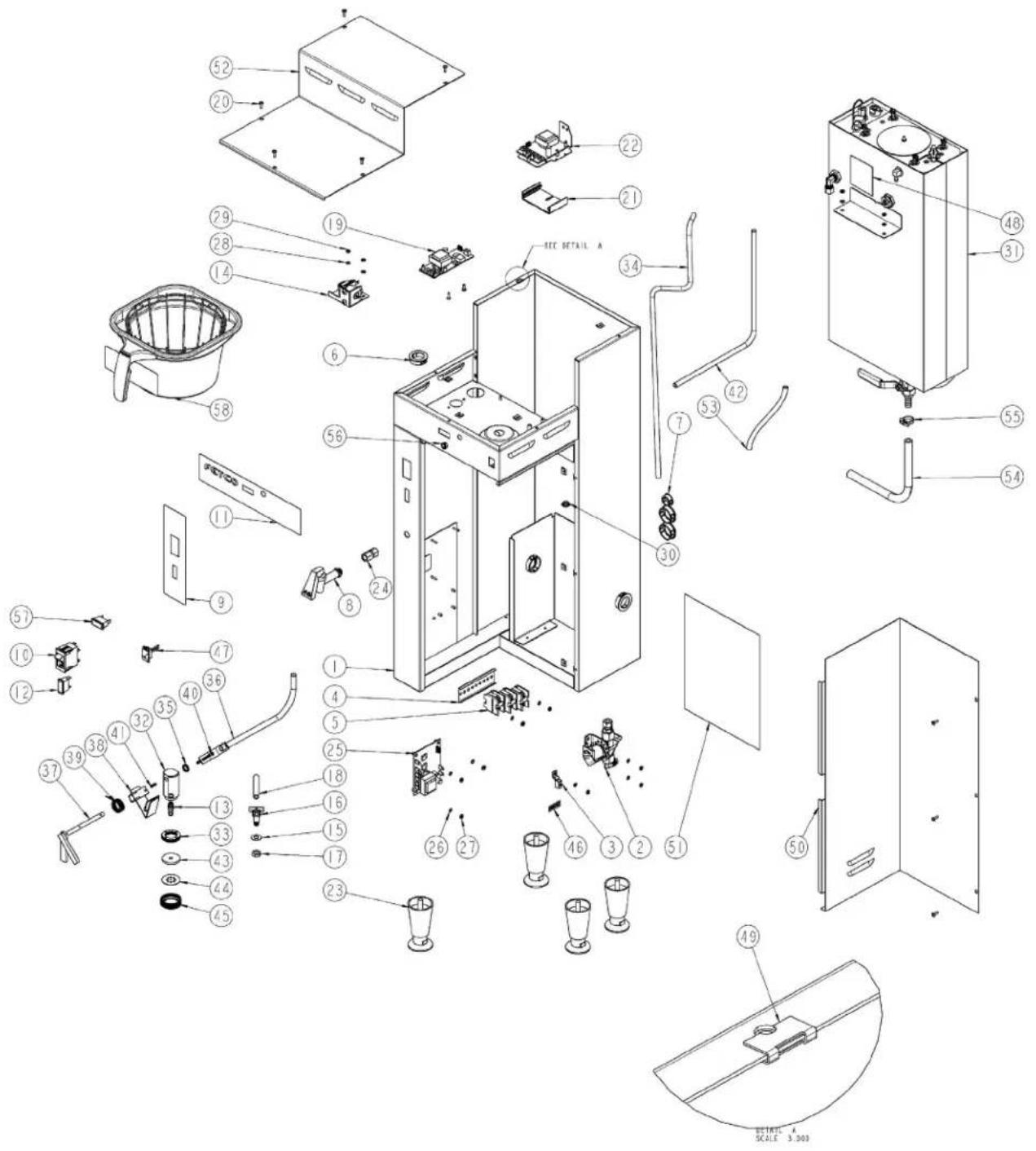
| ITEM # QTY PART # DESCRIPTION | ||||
| 1 | 1 | 001009 | WELDMENT CBS-51H | |
| 2 1 102323 VALVE, S-45 120VAC | ||||
| 2 1 57022 VALVE, S-45 240VAC | EXPORT ONLY | |||
| 3 1 65002 CONNECTOR, COPPER LUG | ||||
| 4 1 52001 TRACK, TERMINAL BLOCK | ||||
| 5 | 3 | 52048 | TERMINAL BLOCK | |
| 6 5 86021 BUSHING, SNAP | 1.375 MTG HOLE | |||
| 7 1 86002 PLUG, DOME, .875 MOUNTING HOLE | ||||
| 8 | 1 71021 FAUCET HPSC-BR-8 REGULAR HANDLE (COMPLETE FAUCET) | |||
| 1 71039 FAUCET, UPPER ASSY. (SUBCOMPONENT OF #8) | ||||
| 1 71003 FAUCET SEAT CUP (SUBCOMPONENT OF #8) | ||||
| 9 1 45014 CBS-52H OVERLAY ARTWORK | ||||
| 10 | 1 52077 BREAKER,CIRCUIT 120VAC ROCKER SWITCH 6 AMP | |||
| 10 | 1 52076 BREAKER,CIRCUIT 220VAC ROCKER SWITCH 6 AMP | EXPORT ONLY | ||
| 11 | 1 | 45016 | NAMEPLATE; OVERLAY | |
| 12 | 1 58027 LAMP, READY INDICATOR, GREEN 120VAC | |||
| 12 | 1 58006 LAMP, READY INDICATOR, GREEN 220VAC | EXPORT ONLY | ||
| 13 | 1 31070 FITTING, HOSE BARB TO MALE PIPE 5/16" | |||
| 14 | 1 102008 ASSEMBLY, DISPENSE SOLENOID LATCH, 120 VAC | |||
| 14 | 1 102039 ASSEMBLY, DISPENSE SOLENOID LATCH, 220 VAC | EXPORT ONLY | ||
| 15 | 1 83041 WASHER, .812"OD X .412"ID, FLAT | |||
| 16 | 1 102028 ASSEMBLY, BYPASS, CBS-60'S, 50'S | |||
| 17 | 1 | 31116 | LOCKNUT 1/8"-27 NPT | |
| 18 | 1 25001 TUBE, BY-PASS SILICONE, 1/4 X 7/16 X 2-7/8" | |||
| 19 | 1 | K033 | DIGITAL THERMOSTAT KIT, 100-120VAC | |
| 19 | 1 | K035 | DIGITAL THERMOSTAT KIT, 200-240VAC (EXPORT) | EXPORT ONLY |
| 20 10 82053 SCREW, # 6-32 X 1/2" TRUSS HD PH | ||||
| 21 | 1 | 002244 | WELDMENT, TIMER PLASTIC TRACK, CBS-60'S, 2"LG | |
| 22 | 1 | K034 | DIGITAL TIMER KIT, 100-120VAC | |
| 22 | 1 | K036 | DIGITAL TIMER KIT, 200-240VAC | EXPORT ONLY |
| 23 | 4 73011 LEG, FLANGE FOOT, 4" HIGH | |||
| 24 | 1 31023 FITTING, COMPR., CONNECTOR, 3/8 TUBE OD X 1/4 FPT | |||
| 25 | 1 | 108034 | ASSEMBLY, BOARD, WATER LEVEL, CONTROL, 100-120 VAC, 50-100K ohm | |
| 25 | 1 | 108035 | ASSEMBLY, BOARD, WATER LEVEL, CONTROL, 200-240 VAC, 50-100K ohm | EXPORT ONLY |
| 26 | 3 83011 WASHER, #6 SCREW SIZE, INTERNAL | |||
| 27 | 3 84001 NUT, HEX, #6-32 MACHINE SCREW | |||
| 28 | 9 83026 WASHER, INTERNAL TOOTH LOCK, #8 SCREW SIZE | |||
| 29 | 9 84002 NUT, HEX, #8-32 MACHINE SCREW | |||
| 30 | 1 | 86013 | PLUG STEEL 7/16" ID, 21/32" HEAD DIAMETER | |
| 31 | 1 | * | ASSEMBLY TANK, CBS-51H-15, SSR | |
| 32 | 1 31068 SPRAY HEAD, 1.5 GAL MACHINES | |||
| 33 | 1 33002 LOCKNUT, SPRAY HEAD | |||
| 34 | 1 32034 TUBE (FILL VALVE TO TANK WATER INLET CONNECTING) | |||
| 35 | 1 24008 SEAL, DISPENSE TUBE, 7/16"DIA | |||
| 36 | 1 002033 WELDMENT DISPENSER TUBE CBS-50's | |||
| 37 | 1 102010 ASSEMBLY, DISPENSE HANDLE | |||
| 38 | 1 102022 ASSEMBLY, DISPENSE LATCH, CBS-50'S | |||
| 39 | 1 85004 SPRING, BREW HANDLE RETURN | |||
| 40 | 1 82018 SCREW, 8-32 X 2-1/4" LG | |||
| 41 | 1 82004 SCREW, 6-32 X 5/8" RND HEAD PHILLIPS | |||
| 42 | 1 32033 TUBE (TANK TO HOT WATER FAUCET CONNECTING) | |||
| 43 | 1 05002 DISK, FLOW, SPRAY CUTTER, .240 DIA | |||
| 44 | 1 | 05014 | SPRAY CUTTER | |
| 45 | 1 31015 LOCKNUT, SPRAY CUTTER | |||
| 46 | 1 | 44004 | LABEL GROUND | |
| 47 | 1 | 102360 | SWITCH, SLIDE, FULL/HALF BATCH SELECTOR, W/ HARNESS | |
| 48 | 1 44024 LABEL, WARNING-HIGH VOLTAGE | |||
| 49 | 8 | 84050 | NUT, CLIP ON (J-NUT), #6-32, 22 - 20 GA., BLACK-PHOSPHATE FINISH | |
| 50 | 1 002023 WELDMENT, LOWER COVER CBS-50'S | |||
| 51 | 1 | * | WIRING DIAGRAM CBS-51H-15 | |
| 52 | 1 01133 COVER, UPPER CBS-51H | |||
| 53 | 1 | 25021 | TUBING, SILICONE (VENT), 1/4"ID X 3/8"OD X 6-1/2"LG | |
| 54 | 1 | 25046 | TUBE, 5/8"OD X 3/8"ID X 15"LG, DRAIN | |
| 55 | 1 86038 CLAMP, HOSE, .670"-.780" DIA RANGE | |||
| 56 | 1 86001 BUSHING, .312 X .500" HEAD DIA. SHORTY | |||
| 57 | 1 58026 LAMP, BREW 120VAC | |||
| 57 | 1 58004 LAMP, BREW 220VAC | EXPORT ONLY | ||
| 58 | 1 | 101165 | ASSEMBLY, BREW BASKET, 16" X 6", DIA HOLE 0.280" (SEE FIG. 5) | |
* For tank assembly and wiring diagram part numbers, call Tech Support at 800-338-2699. Provide the brewer serial number when calling.
Figure 2 – CBS-51H15 Tank Assembly
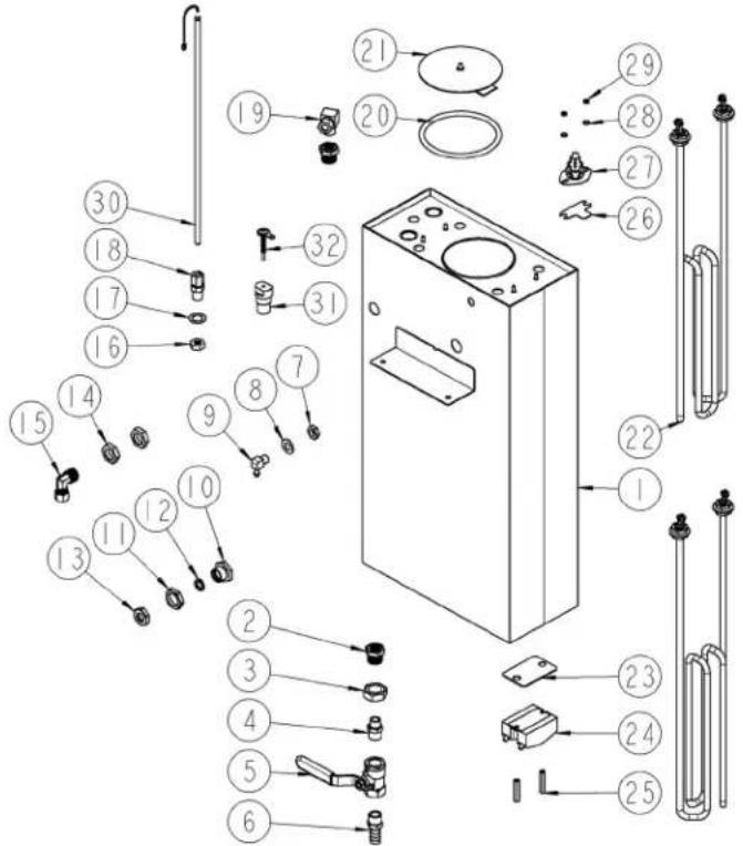
| ITEM # QTY PART # DESCRIPTION |
| 1 1 004072 WELDMENT, TANK, CBS-51H-15, SRR |
| 2 2 31021 BUSHING, 3/4-16 X 1/4 NPSM, HEX HEAD |
| 3 1 84007 NUT, 3/4-16 HEX JAM |
| 4 1 31082 FITTING, HEX NIPPLE, 3/8 MPT X 1/4 MPT |
| 5 1 34004 VALVE, BALL 3/8 FPT X 3/8 FPT |
| 6 1 31054 FITTING, 1/2 HOSE ID X 3/8 MPT |
| 7 1 31116 LOCKNUT 1/8"-27 NPT |
| 8 1 83041 WASHER, .812"OD X .412"ID, FLAT |
| 9 1 31005 FITTING, 90 DEG. ELBOW, 1/4 HOSE ID X 1/8 MPT |
| 10 1 3006 FITTING, TANK, (7/16 DIA DISPENSE TUBE) |
| 11 13007 LOCKNUT, 7/16 STRAIGHT PIPE THREAD |
| 12 1 24008 SEAL, DISPENSE TUBE, 7/16"DIA |
| 13 1 1052 LOCKNUT, 7/16", DISPENSE TUBE SEAL, KEEPER |
| 14 21118 LOCKNUT 3/8"-18 NPT |
| 15 1 1055 FITTING, FILL VALVE INLET |
| 16 1 23249 LOCKNUT 1/4"-18 NPT MODIFIED THREAD |
| 17 13042 WASHER, .875"OD X .562"ID, FLAT |
| 18 1 25098 FITTING, COMPRESSION MALE CONNECTOR |
| 19 1 1027 FITTING, COMPR 90L MALE ELBOW, 3/8 TUBE OD X 1/4 MPT |
| 20 1 24002 O-RING, TANK COVER |
| 21 1 102013 ASSEMBLY, TANK COVER |
| 22 1 or 2 107002 ASSEMBLY, IMMERSION HEATER, 3000W, 240VAC |
| 22 1 or 2 107003 ASSEMBLY, IMMERSION HEATER, 4000W, 240VAC |
| 22 1 or 2 107005 ASSEMBLY, IMMERSION HEATER, 1800W, 120VAC |
| 23 1 03443 ALUMINUM BRACKET FOR SSR |
| 24 1 108071 ASSEMBLY, RELAY, SOLID STATE, 50 A/ 600V |
| 25 2 15013 STANDOFF, 6-32 x1.25 LG.,1/4 HEX WIDTH |
| 26 1 03332 BRACKET 2, ONE SHOT THERMOSTAT |
| 27 13088 THERMOSTAT, SINGLE SHOT, 240V/40A |
| 28 2 83011 WASHER, #6 SCREW SIZE, INTERNAL |
| 29 2 $4045 NUT, HEX 6-32, UNDERSIZED |
| 30 1 K065 ASSEMBLY, DIGITAL TEMP. PROBE, 14.0"LG W/34" CABLE |
| 31 1 21026 HOUSING, WATER LEVEL PROBE 0.140" DIA. |
| 32 1 002010 WELDMENT, WATER LEVEL PROBE, 1.75" LG |
For tank assembly and wiring diagram part numbers, call Tech Support at 800-338-2699. Provide the brewer serial number when calling.
Figure 3 – CBS-52H15 Main Assembly
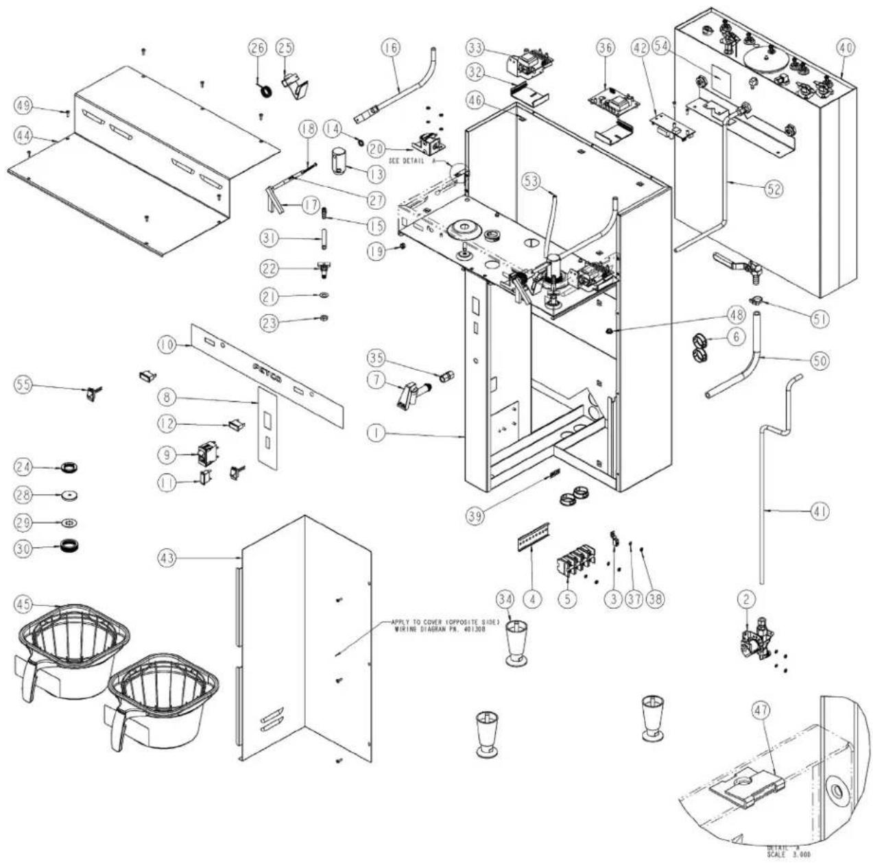
| ITEM # QTY PART # DESCRIPTION | ||||
| 1 | 1 | 001008 | WELDMENT CBS-52H15 | |
| 2 1 102323 VALVE, S-45 120VAC | ||||
| 2 1 57022 VALVE, S-45 240VAC | EXPORT ONLY | |||
| 3 1 65002 CONNECTOR, COPPER LUG | ||||
| 4 1 52001 TRACK, TERMINAL BLOCK | ||||
| 5 | 4 | 52048 | TERMINAL BLOCK | |
| 6 6 86021 BUSHING, SNAP | 1.375 MTG HOLE | |||
| 7 | 1 71021 FAUCET HPSC-BR-8 REGULAR HANDLE (COMPLETE FAUCET) | |||
| 1 71039 FAUCET, UPPER ASSY. (SUBCOMPONENT OF #7) | ||||
| 1 71003 FAUCET SEAT CUP (SUBCOMPONENT OF #7) | ||||
| 8 1 45014 CBS-52H OVERLAY ARTWORK | ||||
| 9 1 52077 BREAKER,CIRCUIT 120VAC ROCKER SWITCH 6 AMP | ||||
| 9 1 52076 BREAKER,CIRCUIT 220VAC ROCKER SWITCH 6 AMP | EXPORT ONLY | |||
| 10 | 1 | 45055 | NAMEPLATE; OVERLAY | |
| 11 1 8027 LAMP, READY INDICATOR, GREEN 120VAC | ||||
| 11 18006 LAMP, READY INDICATOR, GREEN 220VAC | EXPORT ONLY | |||
| 12 2 8026 LAMP, BREW 120VAC | ||||
| 12 28004 LAMP, BREW 220VAC | EXPORT ONLY | |||
| 13 2 1068 SPRAY HEAD, 1.5 GAL MACHINES | ||||
| 14 2 24008 SEAL, DISPENSE TUBE, 7/16"DIA | ||||
| 15 21070 FITTING, HOSE BARB TO MALE PIPE 5/16" | ||||
| 16 2 002033 WELDMENT DISPENSER TUBE CBS-50's | ||||
| 17 2 102010 ASSEMBLY, DISPENSE HANDLE | ||||
| 18 2 2018 SCREW, 8-32 X 2-1/4" LG | ||||
| 19 26001 BUSHING, .312 X .500" HEAD DIA. SHORTY | ||||
| 20 1 102008 ASSEMBLY, DISPENSE SOLENOID LATCH, 120 VAC | ||||
| 20 1 102039 ASSEMBLY, DISPENSE SOLENOID LATCH, 220 VAC | EXPORT ONLY | |||
| 21 2 3041 WASHER, .812"OD X .412"ID, FLAT | ||||
| 22 2 102028 ASSEMBLY, BYPASS, CBS-60'S, 50'S | ||||
| 23 21116 LOCKNUT 1/8"-27 NPT | ||||
| 24 2 3002 LOCKNUT, SPRAY HEAD | ||||
| 25 2 102022 ASSEMBLY, DISPENSE LATCH, CBS-50'S | ||||
| 26 25004 SPRING, BREW HANDLE RETURN | ||||
| 27 2 2004 SCREW, 6-32 X 5/8" RND HEAD PHILLIPS | ||||
| 28 2 05002 DISK, FLOW, SPRAY CUTTER, .240 DIA | ||||
| 29 | 2 | 05014 | SPRAY CUTTER | |
| 30 21015 LOCKNUT, SPRAY CUTTER | ||||
| 31 2 25001 TUBE, BY-PASS SILICONE, 1/4 X 7/16 X 2-7/8" | ||||
| 32 3 002244 WELDMENT, TIMER PLASTIC TRACK, CBS-60'S, 2"LG | ||||
| 33 | 2 | K034 | DIGITAL TIMER KIT, 100-120VAC | |
| 33 2 | K036 DIGITAL TIMER KIT, 200-240VAC | EXPORT ONLY | ||
| 34 3 73011 LEG, FLANGE FOOT, 4" HIGH | ||||
| 35 1 1023 FITTING, COMPR., CONNECTOR, 3/8 TUBE OD X 1/4 FPT | ||||
| 36 | 1 | 108034 | ASSEMBLY, BOARD, WATER LEVEL, CONTROL, 100-120 VAC, 50-100K ohm | |
| 36 1 108035 ASSEMBLY, BOARD, WATER LEVEL, CONTROL, 200-240 VAC, 50-100K ohm | EXPORT ONLY | |||
| 37 11 83026 WASHER, INTERNAL TOOTH LOCK, #8 SCREW SIZE | ||||
| 38 11 84002 NUT, HEX, #8-32 MACHINE SCREW | ||||
| 39 | 1 | 44004 | LABEL GROUND | |
| 40 | 1 | * | ASSEMBLY, TANK CBS-52H-15, SSR | |
| 41 12031 TUBE (FILL VALVE TO TANK WATER INLET CONNECTING) | ||||
| 42 | 1 | K033 | DIGITAL THERMOSTAT KIT, 100-120VAC | |
| 42 1 | K035 DIGITAL THERMOSTAT KIT, 200-240VAC (EXPORT) | EXPORT ONLY | ||
| 43 1 002023 WELDMENT, LOWER COVER CBS-50'S | ||||
| 44 1 01056 COVER, UPPER CBS-52H | ||||
| 45 | 2 | 101165 | ASSEMBLY, BREW BASKET, 16" X 6", DIA HOLE 0.280" (SEE FIG. 5) | |
| 46 | 6 | 84051 | NUT, CLIP ON (J-NUT), #6-32, 18 -16 GA., BLACK-PHOSPHATE FINISH | |
| 47 4 4050 NUT, CLIP ON (J-NUT), #6-32, 22 - 20 GA., BLACK-PHOSPHATE FINISH | ||||
| 48 26013 PLUG STEEL 7/16" ID, 21/32" HEAD DIAMETER | ||||
| 49 12 82053 SCREW, # 6-32 X 1/2" TRUSS HD PH | ||||
| 50 1 25046 TUBE, 5/8"OD X 3/8"ID X 15"LG, DRAIN | ||||
| 51 1 6038 CLAMP, HOSE, .670"-.780" DIA RANGE | ||||
| 52 12032 TUBE (TANK TO HOT WATER FAUCET CONNECTING) | ||||
| 53 | 1 | 25021 | TUBING, SILICONE (VENT), 1/4"ID X 3/8"OD X 6-1/2"LG | |
| 54 1 44024 LABEL, WARNING-HIGH VOLTAGE | ||||
| 55 2 102360 SWITCH, SLIDE, FULL/HALF BATCH SELECTOR, W/ HARNESS | ||||
* For tank assembly and wiring diagram part numbers, call Tech Support at 800-338-2699. Provide the brewer serial number when calling.
Figure 4 – CBS-52H15 Tank Assembly
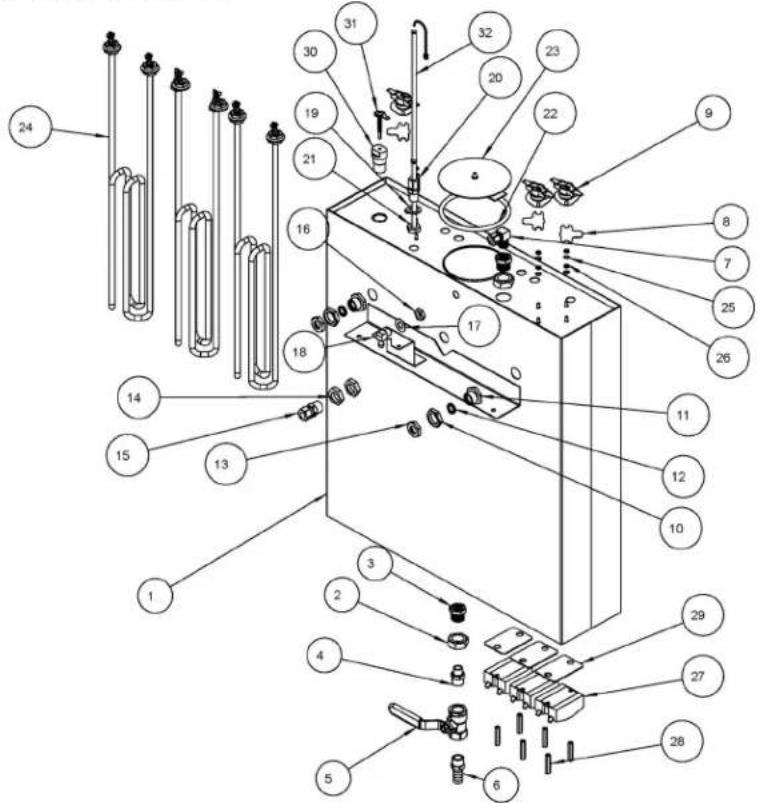
| ITEM # QTY PART # DESCRIPTION | ||
| 1 1 004073 WELDMENT, TANK, CBS-52H-15, SRR | ||
| 2 3 84007 NUT, 3/4-16 HEX JAM | ||
| 3 2 31021 BUSHING, 3/4-16 X 1/4 NPSM, HEX HEAD | ||
| 4 1 31082 FITTING, HEX NIPPLE, 3/8 MPT X 1/4 MPT | ||
| 5 1 34004 VALVE, BALL 3/8 FPT X 3/8 FPT | ||
| 6 1 31054 FITTING, 1/2 HOSE ID X 3/8 MPT | ||
| 7 1 31027 FITTING, COMPRESSION, 90 DEG, MALE ELBOW | ||
| 8 3 03332 BRACKET 2, ONE SHOT THERMOSTAT | ||
| 9 3 53071 THERMOSTAT, SINGLE SHOT, 25A | ||
| 10 2 33007 LOCKNUT, 7/16 STRAIGHT PIPE THREAD | ||
| 11 2 33006 FITTING, TANK, (7/16 DIA DISPENSE TUBE) | ||
| 12 2 24008 SEAL, DISPENSE TUBE, 7/16"DIA | ||
| 13 2 31052 LOCKNUT, 7/16", DISPENSE TUBE SEAL, KEEPER | ||
| 14 2 31118 LOCKNUT 3/8"-18 NPT | ||
| 15 1 31028 FITTING, COMPR. MALE CONNECTOR 3/8 TUBE OD X 3/8 MPT | ||
| 16 1 31116 LOCKNUT 1/8"-27 NPT | ||
| 17 1 83041 WASHER, .812"OD X .412"ID, FLAT | ||
| 18 1 31005 FITTING, 90 DEG. ELBOW, 1/4 HOSE ID X 1/8 MPT | ||
| 19 1 83042 WASHER, .875"OD X .562"ID, FLAT | ||
| 20 1 25098 FITTING, COMPRESSION MALE CONNECTOR | ||
| 21 1 23249 LOCKNUT 1/4"-18 NPT MODIFIED THREAD | ||
| 22 1 24002 O-RING, TANK COVER | ||
| 23 1 102013 ASSEMBLY, TANK COVER | ||
| 24 2 or 3 107002 ASSEMBLY, IMMERSION HEATER, 3000W, 240VAC | ||
| 24 2 or 3 107003 ASSEMBLY, IMMERSION HEATER, 4000W, 240VAC | ||
| 25 6 83011 WASHER, #6 SCREW SIZE, INTERNAL | ||
| 26 6 84045 NUT, HEX 6-32, UNDERSIZED | ||
| 27 3 108071 ASSEMBLY, RELAY, SOLID STATE, 50 A/ 600V | ||
| 28 6 15013 STANDOFF, 6-32 x1.25 LG.,1/4 HEX WIDTH | ||
| 29 3 03443 ALUMINUM BRACKET FOR SSR | ||
| 30 1 21026 HOUSING, WATER LEVEL PROBE 0.140" DIA. | ||
| 31 1 02010 WELDMENT, WATER LEVEL PROBE, 1.75" LG | ||
| 32 1 K065 ASSEMBLY, DIGITAL TEMP. PROBE, 14.0"LG W/34" CABLE |
For tank assembly and wiring diagram part numbers, call Tech Support at 800-338-2699. Provide the brewer serial number when calling.
Figure 5 – Brew Basket Assembly, 16" X 6", Part # 101165
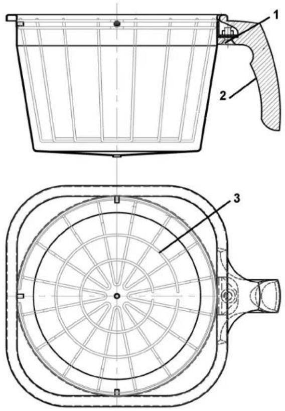
| ITEM | QTY | PART | # DESCRIPTION |
| 1 | 1 | 82096 | HANDLE SCREW |
| 2 | 1 | 23117 | BREW BASKET HANDLE, BLACK(includes magnet) |
| 3 1 9006 WIRE INSERT, 16 X 6 | |||
| NOT SHOWN | 1 | 46011 | WARNING LABEL |
| NOT SHOWN | F001 | PAPER FILTERS, 15" X 5.5"500 PER CASE | |
COLOR BREW BASKET HANDLES
| PART # | DESCRIPTION |
| 23106 | BREW BASKET HANDLE, GREEN |
| 23107 | BREW BASKET HANDLE, ORANGE |
| 23148 | BREW BASKET HANDLE, RED |
Troubleshooting
| Brewing Problem Possible Cause Splution | ||
| Brew handle will not stay downNo power to the brewer | Power switch off. -Turn switch on. | |
| (Brewer lights are not illuminated) | -Make sure the brewer is plugged in.-Check the wall circuit breaker / reset-Turn the brewer power switch off then back on (it has an internal breaker) | |
| Bad timer or dispense latch | assembly.(Brew light does not come on and handle won't stay down) | -Check for voltage reaching the timer from the dispense latch assembly if yes replace timer. If no, replace latch assy. |
| Bad dispense latch assy. | (Brew light does come on and handle won't stay down) | -Replace the dispense latch assembly |
| Bad dispense latch assembly | (brewer buzzes when in brew cycle) | -Replace the dispense latch assembly |
| Brew handle stays down but no water is dispensed | No water reaching the brewer -Make sure the shut off valve is open.-Check water line for kinks; replace line if necessary-Check to see if filter is clogged by changing it. | |
| Short brew levels EVERY BREWWater filter clogged (See details in next sectionSpray head clogged -Clean and or replace (One or Both sides are affected and levels are consistent) | Flow discs in spray heads in upside down | -Reassemble spray heads - bumps on spray cutter face ↓ with flange on flow disc facing ↓ |
| ction) | ||
| the sprayhead | ||
| Timer/s are set too low -Advance timers to proper level. | ||
| Incoming Voltage is too low for timers to function at proper time sequences | -Reset wall circuit breaker as one side may drop out & not flag the breaker.-Call an electrician to find loose connections in the building | |
| Short brew levels SOME BREWSWeak dispense latch assembly(One or Both sides are affected and levels are erratic) | Water filter clogged.(problem is worse during simultaneous brews) | -Replace water filter |
| (usually buzzes during cycle) | -Replace dispense latch assembly. | |
| Water pressure or flow rate is too low or fluctuates too much to support a full brew.(problem is worse in simultaneous brews) | -Make sure brewer has a dedicated water line-Ensure that the shut off valve is open all the way (Never use needle saddle valves)-Increase the diameter of the water line to the brewer and or find stable source. | |
| Brew Time required to fill LUXUS are not the same for both sides | Brewer is not level -With an accurate level, level the brewer front to back and level to right by adjusting the feet. | |
| High brew levels EVERY BREW (overfills but does stop)SOME BREWS | Timer/s are set too high -Adjust timers down to appropriate level | |
| Thermal server not empty | -Empty the server and try again | |
| Brew basket or filter overflows | -Call FETCO Service Dept. to discuss. (800) 338-2699 | |
| Weak CoffeeImproper dose -Measure and confirm correct doseFilter papers -Make sure only one paper is usedCracked dispense tube -See "spray head drips MAJOR", belowLow brew temperature | Spray head missing -Attach spray head assembly. | |
| measure and confirm correct dose | ||
| make sure only one paper is used | ||
| (Temperature inside the hot water tank is set to 205^ F, the metal delivery system drops the temp.) | -Adjust thermostat so the water stream measured at the bottom of the brew basket, 1/3 of the way through the brew cycle, equals 190 degrees + or - 5 degrees | |
| Grounds not saturatedHalf batch used incorrectly -Use smaller "half batch" brew basket-Discountage half batch use-Investigate the need for a smaller brewerWater Softener in use -Move brewer water feed to a non-softened source. | ||
| No bypass EVERY BREW→SOME BREWS→ | Bypass valve closed | -Open bypass valve |
| Flow disc wrong size or missing | -Correct or replace flow disc | |
| Spray head / brew basket drips either side or both MINORCondensation from water tank | Condensation around the sprayhead areadripping through dispense tube | -Wipe sprayhead area after brewing; place an empty container under brew cone when not in use.-Insert an empty brew basket and server under brew heads when not in use |
| Brewing Problem Possible Cause Solution | ||
| Spray head / brew basket drips either side or both MAJOR | Cracked dispense tube/s (This problem starts out minor but gets steadily worse) | -Replace both dispense tubes even if other side is not dripping |
| Fill valve not sealing (Will drip even with power off.) | -See next section - “Brewer won’t stop brewing”, “Bad or stuck fill valve”. | |
| Brewer won’t stop brewing (not same as high brew levels) | Dispense tube cracked -See “sprayhead drops MAJOR” above | |
| Mechanical binding (brew handle stays down / brew light turns off at normal time) | -Re-align the brew handle / brass sprayhead tower / and dispense tube into a straight line by moving brass tower | |
| Water pressure over 75psi -Place a water pressure regulator on the line and reduce to 20-75 psi | ||
| Dispense tube drive screw off. A | 2.5” screw that connects the handle to the dispense tube at the brass sprayhead tower. (handle returns up and brew lamp turns off but brewing continues) | -Ensure that the drive screw is straight (can be straightened by hand while still in the brew handle) and reconnect to the dispense tube. The flange that the drive screw engages MUST be held flat against the brass sprayhead tower, without being able to back out. |
| Water level probe bad or encrusted | with lime. (causes brewer to continue filling hot water tank which will overflow into the brew baskets) | -Clean lime build up on the probe tip and/or tank wall. (Holding the probe wire (green) from the probe end to the body of the brewer should stop the fill if the probe is bad but the liquid level board is good) |
| Bad liquid level control board -Replace the LLC board if grounding the probe end of the (green) probe wire to the body of brewer does not remove the voltage at the fill terminal on the LLC board. | ||
| Coffee tastes too strong | Incorrect dosage -Measure and confirm the correct amount of coffee required | |
| Short brew levels -See “Short brew levels”, above. | ||
| Temperature Problem (brewer only) | Possible Cause Solution | |
| See also LUXUS problems | ||
| Brew water is cold / not hot enough, ready light is OFF.(Before proceeding, make sure water tank refills when water is dispensed. The brewer will not heat unless the tank is full.)Defective liquid level control board. | No power to brewer. -Make sure power switch is on.(No power to thermostat). | -Reset machine circuit breaker.-Check power connection. (plug or hard wire connection).-Check building circuit breaker. (Always reset breaker by switching off, then on.) |
| Bad connections on solid state relay. | (No power to heaters). | -With power on, and water tank full, check LLC board for 120 volts on brown wire and neutral. Replace LLC board if there is no voltage. |
| Defective solid state relay. | (No power to heaters). | -Check input and output voltages on relay. 120 volts on blue wire (input) but no voltage out to heaters indicates a bad relay. |
| Bad heating element/s. | -Check amperage draw on heater wires. 0 amps = bad heater. | |
| Brew water is cold / not hot enough, ready light is ON. | Bad Thermostat(the thermostat believes that it is at set temperature) | -Replace the thermostat and or thermal probe. It's not possible to trouble shoot the probe. |
| Low brew temperature setting on thermostat | -See “Low brew temperature” under “Weak Coffee” section. | |
| Slow to recover temperature(Ready light takes along time to come back on after brewing.) | Brewers with more than one heater can have just one fail | -Check amperage draw on heater wires. 0 amps = bad heater. |
| Hot water tank limed up -Remove access cover to the hot water tank and inspect for lime. Remove the brewer for shop de-liming if build up is thick. | ||
| Boiling | Thermostat set too high for altitude (Denver etc.) | -Reduce temperature setting to 3 degrees below boiling at your altitude |
| Defective thermostat -Replace the thermostat and or thermal probe. It's not possible to trouble shoot the probe. | ||
- CBS-5000 Series Coffee Brewers
- Models:
- Contact Information
- Introduction
- Product Description/Features
- Specifications
- Dimensions & Utility Connections
- Installation
- Keys To A Successful Installation
- Electrical:
- Plumbing:
- General:
- Installation Instructions
- Brewer Setup
- Water Connection
- Electrical Connection
- Final Setup
- Operator Training
- Operating Procedures
- Turn brewer on/off switch (E) to the on position
- Pre-heat the dispensers.
- Legend:
- Remove the brew baskets from the brewer when you are certain that the flow of hot water has stopped from the bottom of the basket.
- Carefully drain any coffee or preheating water from the dispensers through the faucets before starting a coffee brewing cycle.
- Place the thermal dispenser(s) in position under the brew baskets.
- Start the brew cycle in the same manner used to start the water used to preheat the dispensers.
- CAUTION
- Service
- Warranty
- Principles of Operation
- Fill System
- Temperature System:
- Timing System:
- Dispense System:
- To remove the dispense tube:
- To install the dispense tube:
- Adjustments
- Thermostat Adjustment:
- Timer Adjustment:
- Water Level Control Board
- Bypass Adjustment: (Not available on CBS-51H10)
- Brewer Parts
Brand : Fetco
Model : CBS-52H-15
Category : Coffee maker