
AWD-12 - Water dispenser Hatco - Free user manual and instructions
Find the device manual for free AWD-12 Hatco in PDF.


| Product Type | Water Dispenser |
| Brand | Hatco |
| Model | AWD-12 |
| Dimensions (W x D x H) | Approx. 30 x 33 x 50 cm |
| Weight | Approx. 5 kg |
| Power Supply | 120 V / 60 Hz |
| Power Consumption | Heating: 500 W; Cooling: 150 W |
| Temperature Settings | Hot (85-95°C), Cold (5-10°C), Room Temperature |
| Water Tank Capacity | Cold: 3 L; Hot: 1 L |
| Water Source | Bottled or direct connection |
| Faucet Type | Push-lever or paddle handle |
| Safety Features | Child safety lock on hot tap, automatic shutoff, overheat protection |
| Maintenance | Clean water tank and drip tray monthly; descale every 3 months |
| Cleaning | Use mild detergent and soft cloth; avoid abrasive cleaners |
| Spare Parts Available | Yes: drip tray, water tank, heating element, faucet, filters |
| Repairability | Modular design; individual components replaceable by technician |
| Certifications | UL, CE, RoHS |
| Warranty | 1 year limited warranty |
| Usage Instructions | See user manual for initial setup and operation |
Frequently Asked Questions - AWD-12 Hatco
User questions about AWD-12 Hatco
0 question about this device. Answer the ones you know or ask your own.
Ask a new question about this device
Download the instructions for your Water dispenser in PDF format for free! Find your manual AWD-12 - Hatco and take your electronic device back in hand. On this page are published all the documents necessary for the use of your device. AWD-12 by Hatco.
USER MANUAL AWD-12 Hatco
Register Online! (see page 2)

Atmospheric Hot Water Dispenser AWD Series
Installation and Operating Manual
P/N 07.04.356.00

natural_image
Line drawing of a portable industrial water heater with control panel and power outlet (no text or symbols)WARNING
Do not operate this equipment unless you have read and understood the contents of this manual! Failure to follow the instructions contained in this manual may result in serious injury or death. This manual contains important safety information concerning the maintenance, use, and operation of this product. If you're unable to understand the contents of this manual, please bring it to the attention of your supervisor. Keep this manual in a safe location for future reference.
ADVERTENCIA
Important Owner Information ....2
Introduction......2
Important Safety Information....3
Model Description....4
Model Designation....4
Specifications....4
Plug ConfigurationsF 4
Electrical Rating Chart....4
Dimensions....5
Installation....6
General....6
Operation....7
General....7
Dispensing Hot Water....7
Programming the Dispenser....8
Maintenance 9
General....9
CleaningF....9
Draining the Dispenser....9
De-Liming the Dispenser....10
Resetting the High Temperature Safety Switch....11
Troubleshooting Guide ....12
Error CodesF....12
Options and Accessories....13
Limited Warranty....14
Authorized Parts Distributors......Back Cover
IMPORTANT OWNER INFORMATION
Record the model number, serial number (specification label located on the lower side of the unit), voltage, and purchase date Fof Fthe Funit Fin Fthe Fspaces Fbelow. FPlease Fhave Fthis information available when calling Hatco for service assistance.
Model No.F
Serial No.F
VoltageF
Date of PurchaseF
Register your unit!
Completing online warranty registration will prevent delay in obtaining warranty coverage. Access the Hatco website at www.hatcocorp.com, select the Parts & Service pull-down menu, and click on "Warranty Registration".
BusinessF8:00 AMFto 5:00 PM
Hours: Central Standard Time (C.S.T.)
(Summer Hours: June to September –
8:00 AMFto 5:00 PMFC.S.T.
Monday through Thursday
8:00 AMFto 2:30 PMFC.S.T. Friday)
Telephone:F(800) 558-0607; (414) 671-6350
E-mail: partsandservice@hatcocorp.com
Fax: (800) 690-2966 (Parts and Service)
(414) 671-3976 (International)

24 Hour 7 Day Parts and Service Assistance available in the United States and Canada by calling (800) 558-0607.
Additional information can be found by visiting our web site at www.hatcocorp.com.
INTRODUCTION
Hatco Atmospheric Hot Water Dispensers quickly provide 2, 3, or F4 Fquarts F(1.9, F2.8, For F3.8 Fliters) Fof Fhot Fwater Ffor preparation or cleaning. A 12 gallon (45 liter) stainless steel tank provides up to 8 gallons (30 liters) of continuous hot water. The setpoint temperature can be adjusted from 75–195°F (24–91°C), with the factory default setting at 195°F (91°C). The tank can be emptied using the convenient bottom drain.
Hatco FAtmospheric FHot FWater FDispersers Fdesign Ffeatures include Fan Felectronic Ftemperature Fcontroller Fwith Fa Fdigital temperature Fdisplay, FPOWER FON/OFF F(I/O) Fswitch, premeasured dispense buttons, and a manual dispense button for additional water volume options.
Standard Fequipment Fincludes Fa Fstainless Fsteel Fbase, Fa Fred granite Fpowder Fcoated Fbody, F4" F(102 Fmm) Flegs Fand Fa F6' (1829 mm) electrical cord and plug. All electric heating elements are metal sheathed and controlled by a submersed thermistor. The units are protected with a high-temperature limit switch and low-water cutoff.
The Funit Felectrical Fand Fplumbing Fconnections Fare Ffactory assembled and ready for installation.
This Fmanual Fprovides Fthe Finstallation, Fsafety, and Foperating instructions Ffor FAtmospheric FHot FWater FDispersers. FHatco recommends all installation, operating, and safety instructions appearing Fin Fthis Fmanual be Fread Fprior Fto Finstallation For operation of a unit.
Safety information that appears in this manual is identified by the following signal word panels:
WARNING indicates a hazardous situation which, if not avoided, could result in death or serious injury.

CAUTION indicates a hazardous situation which, if not avoided, could result in minor or moderate injury.
NOTICE
NOTICE is used to address practices not related to personal injury.

Read the following important safety information before using this equipment to avoid serious injury or death and to avoid damage to equipment or property.
WARNING
ELECTRIC SHOCK HAZARD:
- LPlug unit into a properly grounded electrical receptacle of the correct voltage, size, and plug configuration. If plug and receptacle do not match, contact a qualified electrician to determine and install the proper voltage and size electrical receptacle.
- LUnit must be installed by qualified, trained installers. Installation Lmust Lconform Lto Lall Llocal Lelectrical Land plumbing codes. Installation by unqualified personnel will Lvoid the Lunit Lwarranty Land Lmay Llead Lto Lelectric shock or Lburn, Las well Las damage to unit Land/or Lits surroundings. Check with local plumbing and electrical inspectors for proper procedures and codes.
- LTurn OFF power switch, unplug power cord, and allow unit Lto Lcool Lbefore Lperforming Lany Lcleaning, adjustments, or maintenance.
- LDO NOT submerge or saturate with water. Unit is not waterproof. Do not operate if unit has been submerged or saturated with water.
- LUnit is not weatherproof. Locate unit indoors where ambient air temperature is a minimum of 70^ (21°C).
- LDo not steam clean or use excessive water on unit.
- LThis unit is not "jet-proof" construction. Do not use jet-clean spray to clean this unit.
•LDo not pull unit by power cord.
- LDiscontinue use if power cord is frayed or worn.
• LDo not attempt to repair or replace a damaged power cord. LThe Lcord Lmust Lbe Lreplaced Lby LHatco, Lan Authorized LHatco LService LAgent, Lor La Lperson Lwith similar qualifications.
- LThis unit must be serviced by qualified personnel only. Service by unqualified personnel may lead to electric shock or burn.
• LUse Lonly LGenuine LHatco LReplacement LParts Lwhen service Lis Lrequired. LFailure Lto Luse LGenuine LHatco Replacement LParts Lwill Lvoid Lall Lwarranties Land Lm subject Loperators Lof Lthe Lequipment Lto Lhazardous electrical voltage, resulting in electrical shock or burn.
Genuine LHatco LReplacement LParts Lare Lspecified Ltd operate safely in the environments in which they are used. Some aftermarket or generic replacement parts do not have the characteristics that will allow them to operate safely in Hatco equipment.
EXPLOSION LHAZARD: LDo not store Lor use gasoline Lor other flammable vapors or liquids in the vicinity of this or any other appliance.
Hatco Corporation is not responsible for the actual food product serving temperature. It is the responsibility of the user to ensure that the food product is held and served at a safe temperature.
This Lunit Lhas Lno L"user-serviceable" Lparts. LIf Lservice required on this unit, contact an Authorized Hatco Service Agent or contact the Hatco Service Department at 800-558-0607 or 414-671-6350; fax 800-690-2966; or International fax 414-671-3976.
WARNING
Make sure all operators have been instructed on the safe and proper use of the unit.
This unit is not intended for use by children or persons with Lreduced Lphysical, Lsensory, Lor Lmental Lcapabilities. Ensure proper supervision of children and keep them away from the unit.
CAUTION
BURN HAZARD:
- LSome exterior surfaces on unit will get hot. Use caution when touching these areas.
- LDrain water may reach temperatures in excess of 200^ (93°C). Use appropriate plumbing materials when installing drain.
Auto-Fill units must be installed with adequate backflow protection and must conform with all federal, state, and local codes.
All water and waste piping and connections shall comply with the International Plumbing Code 2003, International Code Council (ICC), or to the Uniform Plumbing Code 2003, International LAssociation Lof LPlumbing Land LMechanical Officials (IAPMO).
Locate unit at the proper counter height in an area that is convenient for use. The location should be level to prevent the unit or its contents from falling accidentally and strong enough to support the weight of the unit and contents.
NOTICE
Damage to any countertop material caused by heat generated from Hatco equipment is not covered under the Hatco warranty. Contact the manufacturer of the countertop material for application information.
Do not use deionized water. Deionized water will shorten the life of water reservoir and heating element.
Transport unit in upright position. If laid on its side, water must be drained from unit.
Do not overtighten plumbing connections. Overtightening may cause leaks.
Incoming water in excess of 3.0 grains of hardness per gallon L(GPG) (.75 Lgrains of Lhardness Lper liter) Lmust Lbe treated and softened before being supplied to an Atmospheric Hot Water Dispenser. Water containing over 3.0 GPG (.75 GPL) will decrease the efficiency and reduce the operating life of the unit.
Incoming Lwater Lsupply Lmust Lnot Lexceed L140°F L(60°C). Water pressure must be at least 35 psi (241 kPa) and not exceed 80 psi (552 kPa).
Use non-abrasive cleaners on metal Lsurfaces. Abrasive cleaners could scratch the finish of the unit, marring its appearance and making it susceptible to soil accumulation.
Clean Lunit Ldaily Lto Lavoid Lmalfunctions Land Lmaintain sanitary operation.
All Models
Hatco Atmospheric Hot Water Dispensers are equipped with an electronic temperature controller, a digital temperature display, a FPOWER FON/OFF F(I/O) Fswitch, Fpremeasured Fdispensing buttons, and a manual dispense button. The units are protected with a high-temperature limit switch and low-water cut-off.
Atmospheric FHot FWater FDispersers Fdeliver Fpremeasured 2, 3, or 4 quart (1.9, 2.8, 3.8 liter) quantities of hot water at temperatures up to 195°F (91°C). This compact and durable unit Frequres Fminimal counter Fspace Fand Fa Fremovable Fshelf allows access to dispense water into large containers.
Standard Fequipment Fincludes Fa Fstainless Fsteel Fbase, Fa Fred granite powdercoated body, 4" (102 mm) legs, tank drain valve, and a 6' (1829 mm) electrical cord and plug.
A 12 gallon (45 liter) stainless steel tank provides up to 8 gallons (30 liters) of continuous, temperature-controlled water ranging from 75–195°F (24–91°C). The tank is drained easily with a convenient bottom drain fitting.
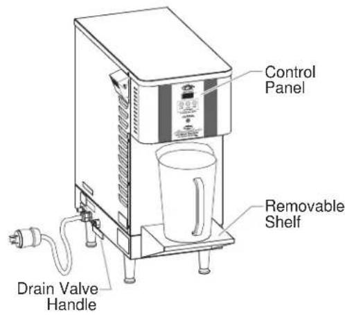
Figure 1. AWD-12 Model
MODEL DESIGNATION

Figure 2. Model Designation
SPECIFICATIONS
Plug Configurations
Units are supplied from the factory with an electrical cord and plug installed. Plugs are supplied according to the applications.
WARNING
ELECTRIC LSHOCK LHAZARD: LPlug Lunit Linto La Lproperly grounded electrical receptacle of the correct voltage, size, and Lplug Lconfiguration. LIf Lplug Land Lreceptacle Ldo Lnot match, Lcontact La Lqualified Lelectrician to determine Land install the proper voltage and size electrical receptacle.
NOTE: Specification label located on the lower side of the unit. See label for serial number and verification of unit electrical information.

NEMA 6-30P
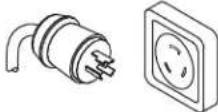
NEMA L6-30P
Figure 3. Plug Configurations
NOTE: Receptacle not supplied by Hatco.
Electrical Rating Chart
| Model | Voltage | Kilowatts | Amps | Plug Configuration | Shipping Weight† |
| AWD-12 | 208 | 5 | 24.0 | NEMA 6-30P* | 80 lbs. (36 kg) |
| 240 | 5 | 20.8 | NEMA 6-30P* | 80 lbs. (36 kg) |
* NEMA L6-30P is optional.
† Unit weight filled with water capacity (12 gallons [45 liters]) is 180 lbs. (82 kg).
Dimensions
| Model | Width (A) | Depth (B) | Height (C) | Footprint Width (D) | Footprint Depth (E) |
| AWD-12 | 13-3/8" (339 mm) | 27-1/2" (698 mm) | 28-1/16" (713 mm) | 10-3/4" (273 mm) | 14-3/4" (375 mm) |
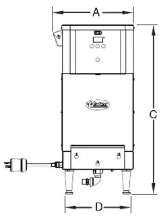

Figure 4. Dimensions
Water Temperature Recovery Table
| Model kW | Degrees of Rise | ||||||||||
| 60°F(33°C) | 70°F(39°C) | 80°F(44°C) | 90°F(50°C) | 100°F(55°C) | 110°F(61°C) | 120°F(66°C) | 130°F(72°C) | 140°F(78°C) | 150°F(83°C) | 160°F(88°C) | |
| AWD-12F5 | 33 gph(125 lph) | 29 gph(110 lph) | 25 gph(95 lph) | 22 gph(83 lph) | 20 gph(75 lph) | 18 gph(68 lph) | 17 gph(64 lph) | 15 gph(57 lph) | 14 gph(53 lph) | 13 gph(49 lph) | 12 gph(45 lph) |
NOTE: gph is gallons per hour; lph is liters per hour.
Cold-Start Heat-up Time
| Model kW | Degrees of Rise | |||
| 60°F(33°C) | 90°F(50°C) | 140°F(78°C) | ||
| AWD-12 | 5F22 MinutesF33 MinutesF52 Minutes | |||
Water Temperature Recovery Time
| Model kW | Degrees of Rise | |||
| 60°F(33°C) | 90°F(50°C) | 140°F(78°C) | ||
| AWD-12 | 5F15 Minutes*F22 Minutes*F35 Minutes* | |||
* Recovery times are after 10 gallons (37 liters) of water have been dispensed.
General
Use Fthe Ffollowing Finformation Fand Fprocedures Fto Finstall Fa Atmospheric Hot Water Dispensers.
WARNING
ELECTRIC SHOCK HAZARD:
- LPlug unit into a properly grounded electrical receptacle of the correct voltage, size, and plug configuration. If plug and receptacle do not match, contact a qualified electrician to determine and install the proper voltage and size electrical receptacle.
- LUnit is Lnot weatherproof. LLocate Lunit Lindoors Lwhere ambient air temperature is a minimum of 70^ (21°C).
CAUTION
Auto-Fill units must be installed with adequate backflow protection and must conform with all federal, state, and local codes.
All water and waste piping and connections shall comply with the International Plumbing Code 2003, International Code Council (ICC), or to the Uniform Plumbing Code 2003, International LAssociation Lof LPlumbing Land LMechanical Officials (IAPMO).
Locate unit at the proper counter height in an area that is convenient for use. The location should be level to prevent the unit or its contents from falling accidentally and strong enough to support the weight of the unit and contents.
- FRemove the unit from the carton.
2.FRemove tape and protective packaging from all surfaces of unit.
NOTE: To prevent delay in obtaining warranty coverage, complete online warranty registration. See the IMPORTANT FOWNER FINFORMATIONFsection for details.
3.FConnect a flexible water supply line to the water inlet on the unit using 1/4" NPT adapter with flare connection (or by using optional 1/4" inlet tubing supplied by Hatco).
NOTE: Water inlet and drain connections must be made with flexible hose.
NOTE: If required, a ball valve or gate valve, line strainer, union(s) and vacuum breaker or other anti-siphon device must be supplied by plumber or installer.
NOTICE
Do not overtighten plumbing connections. Overtightening may cause leaks.
Incoming Lwater Lsupply Lmust Lnot Lexceed L140°F L(60°C) Water pressure must be at least 35 psi (241 kPa) and not exceed 80 psi (552 kPa).
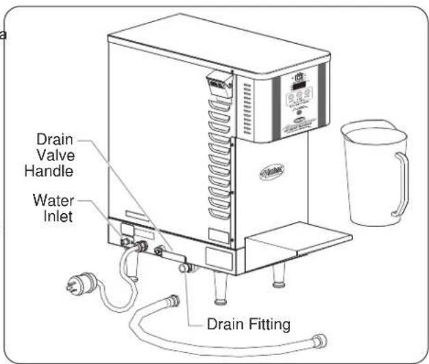
Figure 5: AWD-12 Installation
4.FTighten connections securely.
5.FTurn on water supply and check for leaks.
- A drain fitting is located under the unit for manually draining the dispenser. A male hose connector is included. See MAINTENANCE for draining information.
NOTE: A 3/4" (19 mm) flexible hose may be connected to the heater drain and run to an open sight drain. The drain should not be connected permanently to the sanitary drain system. Check local plumbing code for proper drain installation.
6.FPlace the unit in the desired location.
- Locate the unit in an area where the ambient air temperature is constant and a minimum of 70^ (21°C). Avoid areas that may be subject to active air movements or currents (i.e., near exterior doors, exhaust fans/hoods, air conditioning ducts, etc...).
- FMake sure the unit is at the proper counter height in an area convenient for use.
- FMake sure the countertop is level and strong enough to support the weight of the unit and the water inside.
- Make sure all the feet on the bottom of the unit are positioned securely on the countertop.
NOTICE
Damage Lto Lany Lcountertop Lmaterial Lcaused Lby Lheat generated from Hatco equipment is not covered under the Hatco warranty. Contact the manufacturer of the countertop material for application information.
General
Use the following procedures to operate a Atmospheric Hot Water Dispenser.
WARNING
Read all safety messages in the Important Safety Information section before operating this equipment.
Hatco Corporation is not responsible for the actual food product serving temperature. It is the responsibility of the user to ensure that the food product is held and served at a safe temperature.
Startup
NOTE: Make sure the drain valve handle is in the horizontal (closed) position.
1.FPlug unit into a properly grounded electrical receptacle of the correct voltage, size and plug configuration. See the SPECIFICATIONS section for details.
2.FMove Fthe FPOWER FON/OFF F(I/O)Fswitch Fto Fthe FON F(I) position.
- FThe WATER TEMPERATUREFdisplay Fwill Flight Fup to indicate power is supplied to the unit.
CAUTION
BURN HAZARD: Some exterior surfaces on unit will get hot. Use caution when touching these areas.
3.FThe Funit Fis Fready Fto Fdispense Fwater Fwhen Fthe Fdisplay shows the setpoint water temperature (the factory default setpoint temperature is 195°F [91°C]).
- FThe WATER TEMPERATUREfdisplay Fwill show "E3" while the water begins to fill the tank.
- FThe FWATER FTEMPERATUREFdisplay Fwill Fshow Fthe current water temperature and a red light will glow in the upper left-hand corner of the digital temperature display when the heating elements are energized.
- FThe water Ffills the tank until it is full and the heating elements Fheat Fthe Fwater Funtil Fthe Fwater Ftemperature reaches the setpoint temperature.
NOTE: A temperature setting higher than 195^ F ( 91^ C) will cause nuisance tripping of the high limit switch and is not recommended. If temperature adjustments are required see “Programming The Dispenser.” To reset the high limit switch, see “Resetting The High Temperature Limit Switch.”
Shutdown
1.FMove the POWER ON/OFF (I/O)Fswitch to the OFF (O) position.
- FThe FWATER FTEMPERATUREFdisplay Fwill Fturn Foff Pto indicate power has been shut off to the unit.
Dispensing Hot Water
- FPlace the proper water container for holding hot water on the shelf (or below the dispenser) before dispensing.
NOTE: The shelf can be removed to dispense water into larger containers. To remove the shelf, lift the shelf up and off the mounting screwheads.
2.FPush the appropriate button on the electronic temperature controller to fill a container. Dispensing is controlled by the four dispensing buttons on the front of the unit.
- FThe three VOLUME SELECTIONFbuttons underneath the display dispense at premeasured quantities of 2QT, 3QT, and 4QT as marked.
•F2QT = 2 quarts (1.9 liters)
•F3QT = 3 quarts (2.8 liters)
•F4QT = 4 quarts (3.8 liters)
- FThe red button dispenses and stops water manually.
- Press and hold to dispense water manually. Water will continue to flow until the red button is released.
- Press once after pressing one of the programmed dispense buttons to manually stop dispensing.
NOTE: The dispense amounts can be adjusted if required. See "Programming The Dispenser."
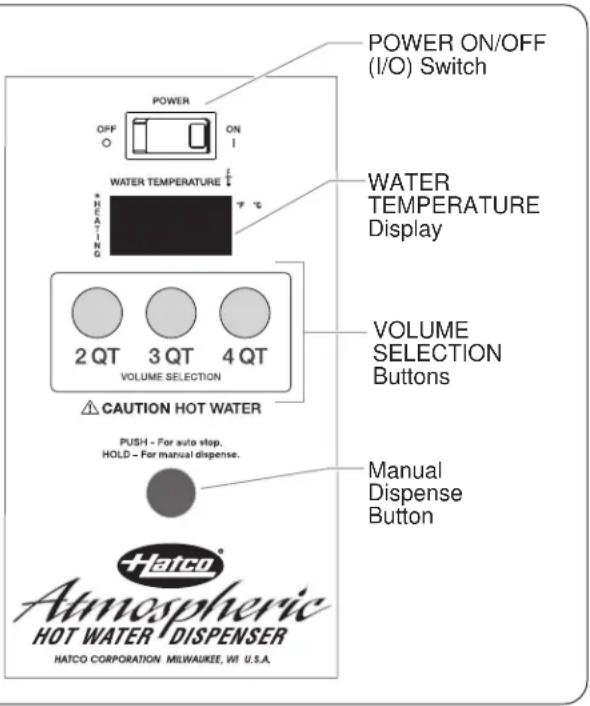
Figure 6. Control Panel
Programming the Dispenser
WARNING
ELECTRIC SHOCK HAZARD: Turn OFF power switch, unplug power cord, and allow unit to cool before performing any cleaning, adjustments, or maintenance.
Dipswitch Panel
A dipswitch panel is located on the back of the control board which Fis Fbehind Fthe Ffront Fpanel Fgraphic Foverlay. FThe Fdip switches have the following functions:
Dipswitch "1" is used to switch between operational mode (RUN) and programming mode (PGM).
Dipswitch "2" is used to change the display from F^ to C^ .
Dipswitch "3" is used to select the type of operation and must be switched to the AWD position for the dispenser to operate.
Dipswitch "4" is not used (can be in either position).
Changing Temperature Display from F° to C°
1.FTurn Fthe FPOWER FON/OFF F(I/O)Fswitch Fto Fthe FOFF F(O) position, and unplug the unit from the electrical receptacle. Cha
2.FRemove the two screws and slide off the top red panel.
3.FMove dipswitch "2" to the C position to change the display from Fahrenheit (F°) to Celsius (C°).
4.FRe-install the top red panel.
5.FPlug the unit into the proper electrical receptacle and turn the POWER ON/OFF (I/O)Fswitch to the ON (I) position.
Changing Temperature Setpoint
1.FTurn Fthe FPOWER FON/OFF F(I/O) Fswitch Fto Fthe FOFF F(O) position and unplug the unit from the electrical receptacle.
2. FRemove the two screws and slide off the top red panel.
3.FMove dipswitch "1" to the PGM position.
4.FPlace the top red panel on unit.
CAUTION
Never operate unit without cover installed.
5.FPlug the unit into the proper electrical receptacle and turn the POWER ON/OFF (I/O)Fswitch to the ONF(I) position.
• FThe display will show (Ftemperature setpoint). This indicates the beginning of the programming sequence.
- FPress the red Fmanual dispense Fbutton Fonce and the display will show the current temperature setpoint.
6.FUse the 2QT and 3QT buttons to adjust the temperature setpoint up or down.
7. FWhen the desired setpoint is shown, press the red manual dispense button to save the change to memory.
NOTE: If no buttons are pressed for a period of 15 seconds, the program will automatically jump to the end of the programming sequence, and the display will read END.
8.FTurn Fthe FPOWER FON/OFF F(I/O)Fswitch Fto Fthe FOFF position and unplug the unit from the electrical receptacle.
9.FRemove the top red panel.
10.FMove dipswitch "1" back to the RUN position.
11.FRe-install the top red panel using the two screws.
12.FPlug the unit into the proper electrical receptacle and turn the POWER ON/OFF (I/O)Fswitch to the ONF(I) position.

Figure 7. Dipswitch Controls
Changing Dispense Time (Water quantity)
Use the following procedure to modify the amount of water the 2QT, 3QT, and/or 4QT buttons dispense.
1.FTurn Fthe FPOWER FON/OFF F(I/O) Fswitch Fto Fthe FOFF F(O) position, and unplug the unit from the electrical receptacle.
2.FRemove the two screws and slide off the top red panel.
3.FMove dipswitch "1" to the PGM position.
4.FPlace the top red panel on unit.
CAUTION
Never operate unit without cover installed.
5.FPlug the unit into the proper electrical receptacle and turn the POWER ON/OFF (I/O)Fswitch to the ONF(I) position.
• FThe display will show FTemperature setpoint). This indicates the beginning of the programming sequence.
6. Press the red manual dispense button to scroll to the desired dispense button to be programmed. The display will identify the VOLUME SELECTIONFbutton by number:
$$ " 1" = 2 Q T \text { VOLUME SELECTION Button } $$
$$ " 2" = 3 Q T V O L U M E S E L E C T I O N B u t t o n $$
$$ " 3" = 4 Q T \text { VOLUME SELECTION Button } $$
7.FPress the red manual dispense button again to display the current dispense time for the specific VOLUME SELECTION Button.
8.FUse the 2QT and 3QT buttons to adjust the dispense time up or down (displayed in seconds by half-second intervals).
9.FWhen the desired dispense time is shown, press the red manual dispense button to save the change to memory and to scroll to the next desired VOLUME SELECTION button.
10.FRepeat step 6 with the next desired dispense button or turn F(O)the POWER ON/OFF (I/O) switch to the OFF (O) position, and unplug the unit from the electrical receptacle.
11.FRemove the top red panel.
12.FMove dipswitch "1" back to the RUN position.
13.FRe-install the top red panel using the two screws.
14.FPlug the unit into the proper electrical receptacle and turn the POWER ON/OFF (I/O)Fswitch to the ONF(I) position.
General
Hatco FAtmospheric FHot FWater FDispersers Fare Fdesigned Fibres recommended that the dispenser be drained prior to moving maximum durability and performance with minimum maintenance. the unit and after performing the "Deliming the Dispenser" procedure.
WARNING
ELECTRIC SHOCK HAZARD:
- LTurn OFF power switch, unplug power cord, and allow unit Lto Lcool Lbefore Lperforming Lany Lcleaning, adjustments, or maintenance.
- LDO NOT submerge or saturate with water. Unit is not waterproof. Do not operate if unit has been submerged or saturated with water.
• LDo not steam clean or use excessive water on unit. - LThis unit is not "jet-proof" construction. Do not use jet-clean spray to clean this unit.
• LUse Lonly LGenuine LHatco LReplacement LParts Lwhen service Lis Lrequired. LFailure Lto Luse LGenuine LHatco Replacement LParts Lwill Lvoid Lall Lwarranties Land Lmay subject Loperators Lof Lthe Lequipment Lto Lhazardous electrical voltage, resulting in electrical shock or burn. Genuine LHatco LReplacement LParts Lare Lspecified Lto operate safely in the environments in which they are used. Some aftermarket or generic replacement parts do not have the characteristics that will allow them to operate safely in Hatco equipment.
This Lunit Lhas Lno L"user-serviceable" Lparts. LIf Lservice required on this unit, contact an Authorized Hatco Service Agent Lor Lcontact Lthe LHatco LService LDepartment Lat 800-558-0607 Lor L414-671-6350; Lfax L800-690-2966; Lor International fax 414-671-3976.
NOTICE
Clean Lunit Ldaily Lto Lavoid Lmalfunctions Land Lmaintain sanitary operation.
Cleaning
To preserve the finish of the Atmospheric Hot Water Dispenser, it is recommended that the exterior surfaces be wiped daily with a clean, damp cloth.
WARNING
Submerging or saturating unit with water will damage the unit and void unit warranty.
NOTICE
Use Lnon-abrasive Lcleaners Land Lcloths Lonly. LAbrasive cleaners and cloths could scratch finish of unit, marring its appearance and making it susceptible to soil accumulation.
- FWipe the exterior surface of the unit with a damp cloth.
2.FStubborn stains Fmay be Fremoved with a good stainless steel Fcleaner For Fa Fnon-abrasive Fcleaner. FHard Fto Freach areas should be cleaned with a small brush and mild soap. - FWipe dry the entire unit using a dry, non-abrasive cloth.
Draining the Dispenser
Flois recommended that the dispenser be drained prior to moving the unit and after performing the "Deliming the Dispenser" procedure.
WARNING
ELECTRIC LSHOCK LHAZARD: LTurn LOFF Lpower Lswitch, unplug Lpower Lcord, Land Lallow Lunit Lto Lcool Lbefore performing any cleaning, adjustments, or maintenance.
1.FShut off the water supply to the unit.
2.FTurn Fthe FPOWER FON/OFF F(I/O) Fswitch Fto Fthe FOFF F(O) position and unplug the unit from the electrical receptacle.
3.FConnect drain hose to the drain fitting on underside of unit.
4.FPlace open end of drain hose in a bucket or open site drain in a manner acceptable to local plumbing codes.
5.FOpen the drain valve by placing the drain handle in the vertical position.
6.FAfter all of the water is drained, place the valve handle in the horizontal position to close the valve.
7.FRemove the drain hose from the drain fitting.

Figure 8. Draining the Water
Deliming the Dispenser
Use the following procedure for periodic cleaning and deliming of the water tank.
NOTE: The lime and mineral content of the supply water will determine how often this procedure must be performed.
NOTE: Perform this procedure when the dispenser will not be used for a period of time, such as the end of the day.
- FMake sure the water tank is full.
2.FTurn Fthe FPOWER FON/OFF (I/O) Fswitch Fto Fthe FOFF F(0) FDrain Fthe Fsolution From Fthe Ftank F(see F"Draining Fthe Dispenser" in this section). position.
3.FDrain 3 gallons (11 liters) of water out of the 12 gallon (45 liter) 8.FRefill Fthe Funit Fwith Fwater Fby Ffollowing Fthe F"Startup" water tank (see "Draining the Dispenser" in this section). procedure in the OPERATION section.
4.FFill the water tank with 3 gallons (11 liters) of off-the-shelf white vinegar (5% vinegar solution) by pouring it slowly into the fill cup on the side of the unit.
Drain Fthe Fsolution Ffrom Fthe Ftank F(see F"Draining Fthe Dispenser" in this section).
8.FRefill Fthe Funit Fwith Fwater Fby Ffollowing Fthe F"Startup" procedure in the OPERATION section. - FDispense water out of the unit until the discharge is clear and all deliming solution has been removed and rinsed.

Figure 9. Deliming the Dispenser
5.FTurn Fthe FPOWER FON/OFF F(I/O) Fswitch Fto Fthe FON F(I) position, Fand Fallow Fthe Funit Fto Frun Fat Fthe Foperating temperature for 1-2 hours.
- FWhile Fthe Finit Fis Fat Foperating Ftemperature, Fdispense 1/2 quart (0.4 liters) of the deliming solution through the dispensing port. This exposes the port to the deliming solution. (Safely discard dispensed solution.)
6.FTurn Fthe FPOWER FON/OFF F(I/O) Fswitch Fto Fthe FOFF F(O) position and allow the deliming solution to remain in the unit for a minimum of 4 hours (preferably, over night.)
NOTE: Steps 7 and 8 may need to be repeated until all deliming solution has been removed.
Resetting the High Temperature Safety Switch
The Atmospheric Water Dispenser is equipped with a manually-resettable Fhigh Flimit Fsafety Fswitch Fthat Fprevents Fthe Fwater temperature from getting dangerously high.
If the water inside the unit exceeds 200^ F ( 93^ C), the safety high Flimit Fswitch Fwill Fshut Fthe Funit Foff. FSetting Fthe Fsetpoint temperature over 195^ F ( 91^ C) will cause nuisance tripping of this safety switch. Hatco does not recommend adjusting the setpoint temperature above 195^ F ( 91^ C).
To reset the safety high limit switch after it activates, follow the following procedure.
1.FTurn Fthe FPOWER FON/OFF F(I/O) Fswitch Fto Fthe FOFF position, unplug the unit from the power source, and allow to cool.
- FThe high limit Fswitch Fcannot be Freset until Fthe water temperature drops below 150°F (66°C).
2. FRemove the front shelf by lifting the shelf up and off of the mounting screwheads.
3.FRemove the front panel.
a.FRemove the six screws that hold the front panel in place.
b.FPull the front panel down and off of the dispenser valve. The rubber grommet should stay attached to the hole in the front panel.
4.FPress the small red button on the high limit safety switch until it clicks. The high limit safety switch is located on the water tank, near the left heating element and the bottom of the tank.
•FThe high limit safety switch is now reset.
5.FReinstall the front panel.
a.FPosition Fthe Ffront Fpanel Fback Finto Fplace. FThe Frubber grommet Fshould Fbe Fpositioned Funder Fthe Fdispenser valve.
b.FAlign Fthe six screw Fholes Fon the Ffront Fpanel with the screw holes on the side panels, and secure in position using the six screws removed in step 3.
6.FReinstall the front shelf.
NOTE: If the high limit safety continues to trip, verify the setpoint is 195^ F ( 91^ C) or lower. If the temperature setpoint is above 195^ F ( 91^ C), adjust the setpoint down to an acceptable level. See “Programming the Dispenser” for adjustment instructions.
NOTE: Contact an Authorized Service Agent if the high limit safety continues to trip and the temperature setpoint is 195°F (91°C) or below.

Figure 10. Resetting the High Temperature Safety Switch
WARNING
This unit must be serviced by qualified personnel only. Service by unqualified personnel may lead to electric shock or burn.
WARNING
ELECTRIC SHOCK HAZARD: Turn OFF power switch, unplug power cord, and allow unit to cool before performing any cleaning, adjustments, or maintenance.
| Symptom Probable Cause Corrective Action | ||
| Unit is not working at all.F | Unit not turned on.FMove FPOWER FON/OFF Fswitch Fto Fthe FON position. | |
| Unit not plugged in.FPlug unit into proper power supply. | ||
| Circuit breaker tripped.FReset circuit breaker. If circuit breaker continues to Ftrip, FContact FAuthorized FService FAgent Fo Hatco for assistance. | ||
| Low-water cut-off activated.FMake sure the unit is supplied with water. | ||
| POWER ON/OFF (I/O) switch is defective.FContact FAuthorized FService FAgent For FHatco Ffor assistance. | ||
| Unit Fdoes Fnot Fdispensed water. | Drain Fvalve Fhandle Fis Fin Fthe Fopen F(vertical) Make sure the drain valve handle is in the closed position. | |
| Water supply is shut off. | Check to make sure the water supply is on. | |
| Dipswitch settings are incorrect. | See “Programming the Dispenser” in the OPERATION section. | |
| High temperature safety switch was activated. | See “Resetting the High Temperature Safety Switch” in the MAINTENANCE section. | |
| Water not hot enough. | Temperature setpoint is set too low. | See the “Changing Temperature Setpoint” procedure in the OPERATION section. |
| Heating element(s) are defective. | Contact Authorized Service Agent or Hatco for assistance. | |
| Incorrect (low) voltage supplied. | Contact Authorized Service Agent or Hatco for assistance. | |
| Water is Fnot Fdispensed at the designated preset amount. | The Funit Fis Fprogrammed Fto Fdispense Fthe improper amount of water. | See the “Changing Dispense Time” procedure in the OPERATION section. |
Error Codes
There are four error codes that may show in the display:
E1: Indicates that the display temperature is out of range or display temperature Fprobe Fis Fmalfunctioning. Contact Authorized Service Agent or Hatco for assistance.
E2: Indicates that the control temperature is out of range or control Ftemperature Fprobe Fis Fmalfunctioning. FContact Authorized Service Agent or Hatco for assistance.
E3: Flindicates that the low water probe has not been satisfied. The heating elements are not yet submersed. Check water supply and water shut-off valve.
H2O: Indicates that the inlet water solenoid has been running continuously for an excessive period of time. Check for problems with the water supply or internal water leak.
Water Filtration System
The water filtration system is available for AWD units as an accessory. The water filtration system helps eliminate sediment buildup inside of the tank leading to a longer life of the unit.
Installing a Water Filtration System
Use the following procedure to install a water filtration system.
NOTE: Before beginning installation, verify that the incoming water pressure is between 50–80 psi (345–552 kPa) and the water temperature is less than 100°F (38°C).
1.FShut off the water supply to the unit.
2.FMove the POWER ON/OFF (I/O) switch to the OFF (O) position, and unplug the unit from the electrical receptacle.
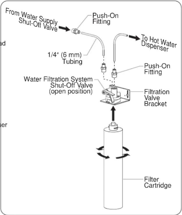
3.FThread Fa Fpush-on Ffitting F(included) Fcoated Fwith Fthread sealant into both the inlet and outlet ports on top of the water filtration valve. Tighten securely.
NOTE: To minimize the effects of restricted flow rate, use the least total amount of 1/4" (6 mm) tubing possible. The total length of tubing from the water supply to the hot water dispenser should not exceed 8' (244 cm). One 10' (305 cm) length of 1/4" (6 mm) tubing is supplied with the water filtration system.
4.FMount the water filtration valve bracket to a solid structure in Fa Fconvenient Flocation Fnear Fthe Fhot Fwater Fdispenser (mounting hardware not supplied).
5.FConnect the water supply to the water filtration valve inlet port using the supplied 1/4" (6 mm) tubing.
NOTE: To identify the inlet port, refer to the arrow on the filtration valve between the ports that indicates the water flow direction through the valve.
a.FCut the 1/4" (6 mm) tubing Fto Fthe appropriate Flength.
Make sure to make clean, straight cuts on the tubing for proper connection to the push-on fittings.
b.FConnect one end of the 1/4" (6 mm) tubing to the water supply shut-off valve and the other to the water filtration valve inlet port. An additional push-on fitting is included for the connection between the water supply shut-off valve and the tubing.

6.FConnect Fthe Fwater Filtration Fvalve Foutlet Fport Fto Fthe Fhot water dispenser using the supplied 1/4" (6 mm) tubing.
a.FCut the 1/4" (6 mm) tubing to the appropriate length. Make sure to make clean, straight cuts on the tubing for proper connection to the push-on fittings.
b.FConnect one end of the 1/4" (6 mm) tubing to the water filtration valve outlet port and the other to the hot water dispenser inlet fitting.
- Install Fthe Fwater Ffilter Fcartridge Funderneath Fthe Fwater filtration valve.
a. FInsert the filter up into the valve.
b.FTwist Fthe Ffilter Fclockwise F1/4 Fturn Funtil Fit Flocks Finto position.
8.FMove both the water supply shut-off valve and the water filtration system shut-off valve to the open position, and check for proper operation/leaks.
flowchart
graph TD
    A["From Water Supply Shut-Off Valve"] --> B["Push-On Fitting"]
    B --> C["To Hot Water Dispenser"]
    D["1/4" (6 mm) Tubing"] --> E["Push-On Fitting"]
    E --> F["Filtration Valve Bracket"]
    G["Water Filtration System Shut-Off Valve (open position)"] --> H["Filtration Valve Bracket"]
    I["Filter Cartridge"] --> J["End"]
Figure 11. Installing a Water Filtration System
NOTE: The water filter cartridge should be replaced after every 15,000 gallons (56,000 liters) of use or at least once per year. Order Hatco P/N 03.05.116.00 for a replacement water filter cartridge.
Locking Plug
A locking NEMA L6-30P plug is available instead of the standard NEMA 6-30 plug (not available for retrofit).
1.LPRODUCT WARRANTY
Hatco Fwarrants Fthe Fproducts Fthat Fit Fmanufactures F(the "Products") Fto Fbe Ffree Ffrom Fdefects Fin Fmaterials Fand workmanship, under normal use and service, for a period of one (1) Fyear Ffrom Fthe Fdate Fof Fpurchase Fwhen Finstalled Fand maintained in accordance with Hatco's written instructions or 18 months from the date of shipment from Hatco. Buyer must establish the Product's purchase date by registering the Product with Hatco or by other means satisfactory to Hatco in its sole discretion.
Hatco warrants the following Product components to be free from defects in materials and workmanship from the date of purchase (subject to the foregoing conditions) for the period(s) of time and on the conditions listed below:
a) LOne (1) Year Parts and Labor PLUS One (1) Additional Year Parts-Only Warranty:
Conveyor Toaster Elements (metal sheathed)
Drawer Warmer Elements (metal sheathed)
Drawer Warmer Drawer Rollers and Slides
Strip Heater Elements (metal sheathed)
Display Warmer Elements (metal sheathed air heating)
Holding Cabinet Elements (metal sheathed air heating)
Heated Well Elements —FHWB Series (metal sheathed)
b) LOne (1) Year Parts and Labor PLUS Four (4) Years Parts-Only Warranty on pro-rated terms that Hatco will explain Lat Buyer's request:
3CS and FR Tanks
c) LOne (1) Year Parts and Labor PLUS Nine (9) Years Parts-Only Warranty on:
Electric Booster Heater Tanks
Gas Booster Heater Tanks
d)LNinety (90) Day Parts-Only Warranty:
Replacement Parts
THE FOREGOING WARRANTIES ARE EXCLUSIVE AND IN LIEU FOF FANY FOTHER FWARRANTY, FEXPRESSED FOR IMPLIED, INCLUDING BUT NOT LIMITED TO ANY IMPLIED WARRANTY OF MERCHANTABILITY OR FITNESS FOR A PARTICULAR FPURPOSE FOR FPATENT FOR FOTHER INTELLECTUAL FPROPERTY FRIGHT FINFRINGEMENT. Without Flimiting Fthe Fgenerality Fof Fthe Fforegoing, FSUCH WARRANTIES DO NOT COVER: Coated incandescent light bulbs, fluorescent lights, heat lamp bulbs, coated halogen light bulbs, halogen heat lamp bulbs, xenon light bulbs, LED light tubes, glass components, and fuses; Product failure in booster tank, fin tube heat exchanger, or other water heating equipment caused Fby Fliming, Fsediment Fbuildup, Fchemical Fattack, For freezing; or Product misuse, tampering or misapplication, improper installation, or application of improper voltage.
2. LLIMITATION OF REMEDIES AND DAMAGES
Hatco's liability and Buyer's exclusive remedy hereunder will be limited solely, at Hatco's option, to repair or replacement using new or refurbished parts or Product by Hatco or a Hatco-authorized service agency (other than where Buyer is located outside of the United States, Canada, United Kingdom, or Australia, in which case Hatco's liability and Buyer's exclusive remedy hereunder will be limited solely to replacement of part under warranty) with respect to any claim made within the applicable warranty period referred to above. Hatco reserves the right to accept or reject any such claim in whole or in part. In the context of this Limited Warranty, "refurbished" means a part For FProduct Fthat Fhas Fbeen Freturned Fto Fits Foriginal specifications by Hatco or a Hatco-authorized service agency. Hatco will not accept the return of any Product without prior written approval from Hatco, and all such approved returns shall be made at Buyer's sole expense. HATCO WILL NOT BE LIABLE, UNDER ANY CIRCUMSTANCES, FOR CONSEQUENTIAL OR INCIDENTAL DAMAGES, INCLUDING BUT NOT LIMITED TO LABOR COSTS OR LOST PROFITS RESULTING FROM THE USE OF OR INABILITY TO USE THE PRODUCTS FOR FFROM FTHE FPRODUCTS FBEING INCORPORATED IN OR BECOMING A COMPONENT OF ANY OTHER PRODUCT OR GOODS.
HATCO AUTHORIZED PARTS DISTRIBUTORS
ALABAMA
Jones McLeod Appl. Svc. BirminghamF205-251-0159
ARIZONA
Service Solutions Group PhoenixF602-234-2443
Byassee Equipment Co. PhoenixF602-252-0402
CALIFORNIA
Industrial Electric Commercial Parts & Service, Inc. Huntington BeachF714-379-7100
Chapman Appl. Service San DiegoF619-298-7106
P & D Appliance Commercial Parts & Service, Inc. S. San FranciscoF650-635-1900
COLORADO
Hawkins Commercial Appliance EnglewoodF303-781-5548
FLORIDA
Whaley Foodservice Repair JacksonvilleF904-725-7800 3Wire Nass Service Co., Inc OrlandoF407-425-2681
B.G.S.I. Pompano BeachF954-971-0456
Comm. Appliance Service TampaF813-663-0313
GEORGIA
TWC Services Mableton 770-438-9797
Heritage Service Group Norcross 866-388-9837 Southeastern Rest. Svc. Norcross 770-446-6177
HAWAII
Burney's Comm. Service, Inc. Honolulu 808-848-1466
Food Equip Parts & Service Honolulu 808-847-4871
ILLINOIS
Parts Town Lombard 708-865-7278 Eichenauer Elec. Service Decatur 217-429-4229 Midwest Elec. Appl. Service Elmhurst 630-279-8000
Cone's Repair Service Moline 309-797-5323
INDIANA
GCS Service IndianapolisF317-545-9655
IOWA
Electric Motor Service Co. Davenport 319-323-1823 Goodwin Tucker Group Des Moines 515-262-9308
KENTUCKY
Service Solutions Group Lexington 859-254-8854 Service Solutions Group Louisville 502-451-5411
LOUISIANA
Chandlers Parts & Service Baton Rouge 225-272-6620
MARYLAND
Electric Motor Service Baltimore 410-467-8080 GCS Service Silver Spring 301-585-7550
MASSACHUSETTS
Ace Service Co., Inc. Needham 781-449-4220
MICHIGAN
Bildons Appliance Service Detroit 248-478-3320 Commercial Kitchen Service Bay City 517-893-4561 Midwest Food Equip. Service Grandville 616-261-2000
MINNESOTA
GCS Service Plymouth 800-345-4221
MISSOURI
General Parts Kansas CityF816-421-5400 Commercial Kitchen Services St. Louis 314-890-0700 Kaemmerlen Parts & Service St. Louis 314-535-2222
NEBRASKA
Anderson Electric Omaha 402-341-1414
NEVADA
Burney's Commercial Las Vegas 702-736-0006 Hi. Tech Commercial Service N. Las Vegas 702-649-4616
NEW JERSEY
Jay Hill Repair FairfieldF973-575-9145
Service Plus Flanders 973-691-6300
NEW YORK
Acme American Repairs, Inc. Brooklyn 718-456-6544 Alpro Service Co. Brooklyn 718-386-2515 Appliance Installation Buffalo 716-884-7425 Duffy's Equipment Services, Inc. Buffalo 800-836-1014 3Wire Northern Plattsburgh 800-634-5005 Duffy's Equipment Services, Inc. Sauquoit 800-836-1014 J.B. Brady, Inc. Syracuse 315-422-9271
NORTH CAROLINA
Authorized Appliance Charlotte 704-377-4501
OHIO
Akron/Canton Comm. Svc. Inc. Akron 330-753-6635 Service Solutions Group Cincinnati 513-772-6600 Commercial Parts and Service Columbus 614-221-0057 Electrical Appl. Repair Service Brooklyn Heights 216-459-8700 E. A. Wichman Co. Toledo 419-385-9121
OKLAHOMA
Hagar Rest. Service, Inc. Oklahoma City 405-235-2184 Krueger, Inc. Oklahoma City 405-528-8883
OREGON
Ron's Service, Inc. Portland 503-624-0890
PENNSYLVANIA
Elmer Schultz Services Philadelphia 215-627-5401 FAST Comm. Appl. Service Philadelphia 215-288-4800 Appliance Installation & Service Pittsburgh 412-809-0244 K & D Service Co. HarrisburgF717-236-9039 Electric Repair Co. Reading 610-376-5444
RHODE ISLAND
Marshall Electric Co. ProvidenceF401-331-1163
SOUTH CAROLINA
Whaley Foodservice Repair W. Columbia 803-791-4420
TENNESSEE
Camp Electric Memphis 901-527-7543
TEXAS
GCS Service Fort Worth 800-433-1804
Armstrong Repair Service Houston 713-666-7100
Cooking Equipment Specialist Mesquite 888-866-9276
Refrigerated Specialist, Inc. Mesquite 888-866-9276
Commercial Kitchen Repair Co. San AntonioF210-735-2811
UTAH
La Monica's Rest. Equip. Service Murray 801-263-3221
VIRGINIA
Daubers Norfolk 757-855-4097
Daubers SpringfieldF703-866-3600
WASHINGTON
3Wire Restaurant Appliance Seattle 800-207-3146
WISCONSIN
A.S.C., Inc. Madison 608-246-3160 A.S.C., Inc. Milwaukee 414-543-6460
CANADA
ALBERTA
Key Food Equipment Service Edmonton 780-438-1690
BRITISH COLUMBIA
Key Food Equipment Service VancouverF604-433-4484
Key Food Equipment Service Victoria 250-920-4888
MANITOBA
Air Rite, Inc. Winnipeg 204-895-2300
NEW BRUNSWICK
EMR Services, Ltd. Moncton 506-855-4228
ONTARIO
R.G. Henderson Ltd. Toronto 416-422-5580
Choquette - CKS, Inc. Ottawa 613-739-8458
QUÉBEC
Choquette - CKS, Inc. Montreal 514-722-2000
Choquette - CKS, Inc. Québec City 418-681-3944
UNITED KINGDOM
Marren Group Northants +44(0)1933 666233
HATCO CORPORATION
P.O. Box 340500
Milwaukee, WI 53234-0500 U.S.A.
(800) 558-0607 (414) 671-6350
Parts and Service Fax (800) 690-2966
International Fax (414) 671-3976
partsandservice@hatcocorp.com
www.hatcocorp.com
Register your unit online!
See IMPORTANT OWNER INFORMATION section for details
- Atmospheric Hot Water Dispenser AWD Series
- Installation and Operating Manual
- WARNING
- ADVERTENCIA
- IMPORTANT OWNER INFORMATION
- Register your unit!
- INTRODUCTION
- ELECTRIC SHOCK HAZARD:
- CAUTION
- BURN HAZARD:
- NOTICE
- All Models
- MODEL DESIGNATION
- SPECIFICATIONS
- Plug Configurations
- General
- Startup
- Shutdown
- Dispensing Hot Water
- Programming the Dispenser
- Dipswitch Panel
- Changing Temperature Display from F° to C°
- Changing Temperature Setpoint
- Never operate unit without cover installed.
- Changing Dispense Time (Water quantity)
- Cleaning
- Draining the Dispenser
- Deliming the Dispenser
- Resetting the High Temperature Safety Switch
- Error Codes
- Water Filtration System
- Installing a Water Filtration System
- Locking Plug
- 1.LPRODUCT WARRANTY
- LLIMITATION OF REMEDIES AND DAMAGES
- HATCO AUTHORIZED PARTS DISTRIBUTORS
- ALABAMA
- ARIZONA
- CALIFORNIA
- COLORADO
- FLORIDA
- GEORGIA
- HAWAII
- ILLINOIS
- INDIANA
- IOWA
- KENTUCKY
- LOUISIANA
- MARYLAND
- MASSACHUSETTS
- MICHIGAN
- MINNESOTA
- MISSOURI
- NEBRASKA
- NEVADA
- NEW JERSEY
- NEW YORK
- NORTH CAROLINA
- OHIO
- OKLAHOMA
- OREGON
- PENNSYLVANIA
- RHODE ISLAND
- SOUTH CAROLINA
- TENNESSEE
- TEXAS
- UTAH
- VIRGINIA
- WASHINGTON
- WISCONSIN
- CANADA
- ALBERTA
- BRITISH COLUMBIA
- MANITOBA
- NEW BRUNSWICK
- ONTARIO
- QUÉBEC
- UNITED KINGDOM
Brand : Hatco
Model : AWD-12
Category : Water dispenser