AJ-86 - Dishwasher Jackson - Free user manual and instructions
Find the device manual for free AJ-86 Jackson in PDF.


| Product Type | Commercial Undercounter Dishwasher |
| Brand | Jackson |
| Model | AJ-86 |
| Dimensions (W x D x H) | 24" x 25.5" x 34.5" |
| Weight | 150 lbs |
| Power Supply | 208-240V, 60Hz, 1 Phase |
| Amperage | 20 A |
| Water Connection | 3/4" NPT, Hot Water Supply |
| Drain Connection | 1 1/2" NPT Gravity Drain |
| Cycle Time | 90 seconds (wash + rinse) |
| Wash Temperature | 140°F - 160°F (60°C - 71°C) |
| Rinse Temperature | 180°F - 195°F (82°C - 90°C) for sanitization |
| Capacity | Racks: 20" x 20", up to 60 racks per hour |
| Control Type | Electromechanical timer |
| Construction | Stainless steel interior and exterior |
| Door Type | Lift-up door with counterweight |
| Safety Features | Door safety switch, high-limit thermostat |
| Maintenance | Daily: clean spray arms, check drain; Weekly: descale, inspect seals |
| Spare Parts | Available from Jackson parts distributors |
| Warranty | 1 year parts and labor |
Frequently Asked Questions - AJ-86 Jackson
User questions about AJ-86 Jackson
0 question about this device. Answer the ones you know or ask your own.
Ask a new question about this device
Download the instructions for your Dishwasher in PDF format for free! Find your manual AJ-86 - Jackson and take your electronic device back in hand. On this page are published all the documents necessary for the use of your device. AJ-86 by Jackson.
USER MANUAL AJ-86 Jackson
AND ASSOCIATED OPTION PACKAGES INCLUDING:
SIDE LOADER D226 EXTERNAL STEAM BOOSTER

Warewashing Systems
Jackson WWS, INC.
P.O. Box 1060
Barbourville, KY. 40906
(606) 523-9795
Fax: (606) 523-9196
www.jacksonwws.com
October 06, 2015
P/N 7610-002-30-93 (Revision K)
MANUFACTURERS WARRANTY
ONE YEAR LIMITED PARTS & LABOR WARRANTY
ALL NEW JACKSON DISHWASHERS ARE WARRANTED TO THE ORIGINAL PURCHASER TO BE FREE FROM DEFECTS IN MATERIAL OR WORKMANSHIP, UNDER NORMAL USE AND OPERATION FOR A PERIOD OF (1) ONE YEAR FROM THE DATE OF PURCHASE, BUT IN NO EVENT TO EXCEED (18) EIGHTEEN MONTHS FROM THE DATE OF SHIPMENT FROM THE FACTORY.
Jackson WWS agrees under this warranty to repair or replace, at its discretion, any original part which fails under normal use due to faulty material or workmanship during the warranty period, providing the equipment has been unaltered, and has been properly installed, maintained and operated in accordance with the applicable factory instruction manual furnished with the machine and the failure is reported to the authorized service agency within the warranty period. This includes the use of factory specified genuine replacement parts, purchased directly from a Jackson authorized parts distributor or service agency. Use of generic replacement parts may create a hazard and void warranty certification.
The labor to repair or replace such failed part will be paid by Jackson WWS, within the continental United States, Hawaii and Canada, during the warranty period provided a Jackson WWS authorized service agency, or those having prior authorization from the factory, performs the service. Any repair work by persons other than a Jackson WWS authorized service agency is the sole responsibility of the customer. Labor coverage is limited to regular hourly rates, overtime premiums and emergency service charges will not be paid by Jackson WWS.
Accessory components not installed by the factory carry a (1) one year parts warranty only. Accessory components such as table limit switches, pressure regulators, pre rinse units, etc. that are shipped with the unit and installed at the site are included. Labor to repair or replace these components is not covered by Jackson WWS.
This warranty is void if failure is a direct result from shipping, handling, fire, water, accident, misuse, acts of god, attempted repair by unauthorized persons, improper installation, if serial number has been removed or altered, or if unit is used for purpose other than it was originally intended.
TRAVEL LIMITATIONS
Jackson WWS limits warranty travel time to (2) two hours and mileage to (100) one hundred miles. Jackson WWS will not pay for travel time and mileage that exceeds this, or any fees such as those for air or boat travel without prior authorization.
WARRANTY REGISTRATION CARD
The warranty registration card supplied with the machine must be returned to Jackson WWS within 30 days to validate the warranty.
REPLACEMENT PARTS WARRANTY
Jackson replacement parts are warranted for a period of 90 days from the date of installation or 180 days from the date of shipment from the factory, which ever occurs first.
PRODUCT CHANGES AND UPDATES
Jackson WWS reserves the right to make changes in design and specification of any equipment as engineering or necessity requires.
THIS IS THE ENTIRE AND ONLY WARRANTY OF JACKSON WWS. JACKSON'S LIABILITY ON ANY CLAIM OF ANY KIND, INCLUDING NEGLIGENCE, WITH RESPECT TO THE GOODS OR SERVICES COVERED HEREUNDER, SHALL IN NO CASE EXCEED THE PRICE OF THE GOODS OR SERVICES OR PART THEREOF WHICH GIVES RISE TO THE CLAIM.
THERE ARE NO WARRANTIES, EXPRESSED OR IMPLIED, INCLUDING FOR FITNESS OR MERCHANTABILITY, THAT ARE NOT SET FORTH HEREIN, OR THAT EXTEND BEYOND THE DURATION HEREOF. UNDER NO CIRCUMSTANCES WILL JACKSON WWS BE LIABLE FOR ANY LOSS OR DAMAGE, DIRECT OR CONSEQUENTIAL, OR FOR THE DAMAGES IN THE NATURE OF PENALTIES, ARISING OUT OF THE USE OR INABILITY TO USE ANY OF ITS PRODUCTS.
ITEMS NOT COVERED
This warranty does not cover cleaning or deliming of the unit or any component such as, but not limited to, wash arms, rinse arms or strainers at anytime. Nor does it cover adjustments such as, but not limited to timer cams, thermostats or doors, beyond 30 days from the date of installation. In addition, the warranty will only cover the replacement of wear items such as curtains, drain balls, door guides or gaskets during the first 30 days after installation. Also, not covered are conditions caused by the use of incorrect (non-Commercial) grade detergents, incorrect water temperature or pressure, or hard water conditions.
STOP!
PARE!
ARRET!
CALL 1-888-800-5672 TO REGISTER THIS PRODUCT! FAILURE TO DO SO WILL VOID THE WARRANTY!
LLAM E AL 1-888-800-5672 PARA REG ISTRAR ESTE PRO DUC TO! AL NO HACERIO LA GARANTIA SERA ANULADA!
S.V.P. APPELER 1-888-800-5672 PO UR ENREG ISTRER C E PRO DUIT, LA GARANTIE SERA ANNULEE PO UR TO UT PRO DUIT NON - ENREG ISTREE
| REVISION | REVISION DATE | MADE BY | APPLICABLE ECN | DETAILS |
| D 04-06 | 05 MAW | 6999, 71937217, 70647212, 72596685, 70966964, 7006 | Updated drawings for limit switch actuators. Changed AJ-86 drain plumbing copper lengths. Added rack rail stabilizer kit. Replaced heater 04540-121-76-93 with 04540-002-29-82. Updated installation instructions. Added 3 instruction sheets for limit switches. Added instruction sheet for curtains. Added AJ-86CGP & AJ-100CGP models. | |
| E 02-02 | 06 MAW 7600,7558 | Added gas exhaust fan schematic, updated electric exhaust fan schematic, updated dimensions pages. Replace Drain Weldment 05700-021-68-28 with 05700-002-51-12. | ||
| F 05-02 | 06 MAW | 7572, 77307634, 77437428, 75717554, 74757463, 74627367, 7789 | Pawl bar for AJ-86 R-L unit with a side loader option. Updated scrap basket drawings. Vent cowl assembly for a hooded side loader. Service instructions for replacing wash/rinse motors. Added prison pawl bar packages. Thermostat replacement kits, updated drain quench assembly, replaced wash thermostat 05930-121-67-72 with 05930-003-13-65. Heater replacement instructions. Updated steam booster schematic. Rinse fill motor assembly. Wash, rinse & PSI decals. Update door assembly numbers.Drain quench kit. | |
| PG, 116 | 04-19-07 | MAW | 7898 | Added 09905-003-32-20 fan load decal. |
| 5 thru 22, 104 | 09-29-2007 MAW N/A | Updated dimensions page. Removed alternate table limit switches. | ||
| G 10-09 | 2009 KJS 8044 | Changed the part from a weldment (05700-021-67-50) to a casting (09515-003-58-12). | ||
| H | 08-12-2013 | RLC | QOF NDB-219 | Updated Manufacturer information. |
| I | 09-15-2014 | KAP | N/A | Updated Jackson Logo |
| J | 02-06-2014 | KAP | N/A | Updated temperatures on pg's 7, 8, 13, 14, 19, and 20. Updated drawing on pg. 39 |
| K | 10-06-2015 | KAP | N/A | Updated rack rail assembly on pg. 97 |

AJ-64CS
AJ = AJ series of rack conveyors
64 = 64" wide machine
86 = 86" wide machine
100 = 100" wide machine
CE = Electrically heated, hot water sanitizing machine
CS = Steam heated, hot water sanitizing machine
CGP = Gas heated, hot water sanitizing machine
Model:
Serial No.:
Installation Date:
Service Rep. Name:
Phone No.:
Jackson WWS, INC. provides technical support for all of the dishmachines detailed in this manual. We strongly recommend that you refer to this manual before making a call to our technical support staff. Please have this manual with you when you call so that our staff can refer you, if necessary, to the proper page. Technical support is available from 8:00 a.m. to 5:00 p.m. (EST), Monday through Friday. Technical support is not available on holidays. Contact technical support toll free at 1-888-800-5672. Please remember that technical support is available for service personnel only.
TABLE OF CONTENTS
SECTION DESCRIPTION PAGE
I. SPECIFICATION INFORMATION
Operating Characteristics 2
Electrical Requirements 3
D226 Steam Booster Parameters 4
AJ-64 Electric - Left to Right 5
AJ-64 Electric - Right to Left 6
AJ-64 Gas - Left to Right 7
AJ-64 Gas - Right to Left 8
AJ-64 Steam - Left to Right 9
AJ-64 Steam - Right to Left 10
AJ-86 Electric - Left to Right 11
AJ-86 Electric - Right to Left 12
AJ-86 Gas - Left to Right 13
AJ-86 Gas - Right to Left 14
AJ-86 Steam - Left to Right 15
AJ-86 Steam - Right to Left 16
AJ-100 Electric - Left to Right 17
AJ-100 Electric - Right to Left 18
AJ-100 Gas - Left to Right 19
AJ-100 Gas - Right to Left 20
AJ-100 Steam - Left to Right 21
AJ-100 Steam - Right to Left 22
Side Loader (Left to Right) Dimensions 23
Side Loader (Right to Left) Dimensions 24
Side Loader (Installed) Dimensions 25
D226 Steam Booster Dimensions 26
D226 Steam Booster Plumbing Line Drawings 27
Typical Electric and Gas Booster Dimensions 28
II. INSTALLATION & OPERATION INSTRUCTIONS
Installation Instructions 30
Deliming Operations 33
Curtain Installation Diagram 34
Side Loader Installation & Operation Instructions 35
D226 Steam Booster Installation & Operation Instructions 36
Gas Conveyor Hose Installation 38
Dishmachine Operating Instructions 40
Detergent Control 42
Striker Plate Limit Switch Installation Instructions 43
III. PREVENTATIVE MAINTENANCE
General Maintenance 45
D226 Maintenance 46
Lubrication Chart for Drive Gear 47
Drive Motor Gear Reducer Preventative Maintenance 48
IV. TROUBLESHOOTING SECTION
Common Problems 50
D226 Common Problems 52
TABLE OF CONTENTS
PARTS
VI. PARTS SECTION
AJ-64 Control Box Assembly 54
AJ-86/AJ-100 Control Box Assembly 56
Motor Overload Chart 58
Heater Box Assembly 59
Heater Assembly 60
Frame Weldments/Front Dress Panels 62
Prewash Plumbing Assembly 63
Incoming Plumbing Assembly 64
Rinse Header Plumbing Assembly (CGP Models) 66
External Electric Booster Option Incoming Plumbing 67
External Electric Booster Option Outlet Plumbing 68
WPRK Plumbing Option 69
3/4" Solenoid Valve & 3/4" NPT Vacuum Breaker Repair Parts Kits 70
Steam Unit Wash Tank Coil Assembly 71
Steam Inlet Plumbing (Left to Right) 72
Steam Inlet Plumbing (Right to Left) 74
Steam Outlet Plumbing (Left to Right) 76
Steam Outlet Plumbing (Right to Left) 77
Gas Coil Assembly (CGP Models) 78
Rinse Booster Tank Assembly (CGP Models) 79
Recirculating Pump Assembly (CGP Models) 80
Hose Connections (CGP Models) 81
AJ-64 Series Drain Plumbing Assemblies 82
AJ-86 & AJ-100 Drain Plumbing Assemblies (Left to Right) 83
AJ-86 & AJ-100 Drain Plumbing Assemblies (Right to Left) 84
Drain Quench Assembly 85
Prewash & Wash Motor Assemblies 86
Prewash & Wash Pump Weldments 87
Prewash & Upper Wash Arm Assemblies 88
Lower Wash Arm Assembly 89
Upper & Lower Power Rinse Arm Assemblies 90
Final Rinse Assembly 91
Drive Assembly 92
Door Assemblies 94
Pawl Bar Roller Bracket 95
AJ-64 & AJ-86 Pawl Bar Assemblies 96
AJ-64 Rack Rail Assembly 97
Miscellaneous Parts & Weldments 98
Manifolds/Strainer Support Weldments 99
Strainers 10
Float Switch Components/Scrap Basket Assembly 10
Curtains/Tub Magnets 10:
Vent Cowl Assembly/Vent Scoop Option 10
Exhaust Fan Control Option/Table Limit Switch Options 104
SIDE LOADER SECTION
Side Loader Track Assembly/Leg Replacements 105
Side LoaderPawl Bar Assemblies 106
Side Loader Vent Cowl Option 107
D226 STEAM BOOSTER SECTION
Control Box Assembly 108
Plumbing Assembly 109
Go*Box Components 111
Rinse Fill Motor Option 112
TABLE OF CONTENTS
ELECTRICAL SCHEMATICS
VII. ELECTRICAL SCHEMATICS
AJ-64CE
208-230 Volt, 60 Hz, 1 Phase Primary Side 114
208-230 Volt, 60 Hz, 1 Phase Secondary Side 115
208-230 Volt, 60 Hz, 3 Phase Primary Side 116
208-230 Volt, 60 Hz, 3 Phase Secondary Side 117
460-575-600 Volt, 60 Hz, 3 Phase Primary Side 118
460-575-600 Volt, 60 Hz, 3 Phase Secondary Side 119
AJ-64CS
208-230 Volt, 60 Hz, 1 Phase Primary Side 120
208-230 Volt, 60 Hz, 1 Phase Secondary Side 121
208-230 Volt, 60 Hz, 3 Phase Primary Side 122
208-230 Volt, 60 Hz, 3 Phase Secondary Side 123
460-575-600 Volt, 60 Hz, 3 Phase Primary Side 124
460-575-600 Volt, 60 Hz, 3 Phase Secondary Side 125
AJ-86CE & AJ-100CE
208-230 Volt, 60 Hz, 1 Phase Primary Side 126
208-230 Volt, 60 Hz, 1 Phase Secondary Side 127
208-230 Volt, 60 Hz, 3 Phase Primary Side 128
208-230 Volt, 60 Hz, 3 Phase Secondary Side 129
460-575-600 Volt, 60 Hz, 3 Phase Primary Side 130
460-575-600 Volt, 60 Hz, 3 Phase Secondary Side 131
AJ-86CS & AJ-100CS
208-230 Volt, 60 Hz, 1 Phase Primary Side 132
208-230 Volt, 60 Hz, 1 Phase Secondary Side 133
208-230 Volt, 60 Hz, 3 Phase Primary Side 134
208-230 Volt, 60 Hz, 3 Phase Secondary Side 135
460-575-600 Volt, 60 Hz, 3 Phase Primary Side 136
460-575-600 Volt, 60 Hz, 3 Phase Secondary Side 137
AJ-86CGP & AJ100CGP
208-230 Volt, 60 Hz, 1 Phase Primary Side 138
208-230 Volt, 60 Hz, 1 Phase Secondary Side 139
208-230 Volt, 60 Hz, 3 Phase Primary Side 140
208-230 Volt, 60 Hz, 3 Phase Secondary Side 141
460-575-600 Volt, 60 Hz, 3 Phase Primary Side 142
460-575-600 Volt, 60 Hz, 3 Phase Secondary Side 143
Exhaust Fan Hook-Up Schematic 144
D226 Steam Booster/Drain Quench/Conveyor Side Loader Schematics 145
VIII. MAINTENANCE & REPAIR CENTERS 146
SECTION 1: SPECIFICATION INFORMATION
SECTION 1: SPECIFICATION INFORMATION OPERATING CHARACTERISTICS
RACKS PER HOUR:
AJ-64-86-100CE/CS/CGP 287
DISHES OR GLASSES PER HOUR:
AJ-64-86-100CE/CS/CGP 7200
PREWASH TANK CAPACITY (GALLONS):
AJ-86CE/CS/CGP 16
AJ-100CE/CS/CGP 16
WASH TANK CAPACITY (GALLONS):
AJ-64-86-100CE/CS/CGP 15.4
POWER RINSE TANK CAPACITY (GALLONS):
AJ-86CE/CS/CGP 15.4
AJ-100CE/CS/CGP 15.4
PREWASH PUMP CAPACITY (GPM):
AJ-86CE/CS/CGP 120
AJ-100CE/CS/CGP 270
WASH PUMP CAPACITY
GALLONS PER MINUTE (ALL MODELS): 270
POWER RINSE PUMP CAPACITY
GALLONS PER MINUTE (ALL MODELS): 270
VENTING REQUIREMENTS (CFM)(100% CAP.):
INPUT END 200
OUTPUT END 400
TOTAL 600
CONVEYOR SPEED (FPM):
AJ-64-86-100CE/CS/CGP MACHINES 8.0
GALLONS PER RACK:
AJ-64-86-100CE/CS/CGP MACHINES .77
WATER TEMPERATURES:
AJ-64-86-100CE/CS/CGP MODELS:
WASH (MINIMUM) 150°F
POWER RINSE (MINIMUM) 160°F
FINAL RINSE (MINIMUM) 180°F
FLOW PRESSURE (PSI) 20 ± 5
FLOWRATE (GPM):
AJ-64-86-100CE/CS/CGP 3.7
STEAM COIL TANK HEAT (CS MODELS ONLY):
| STEAM INLET PRESSURE (PSIG) | 10-20 |
| STEAM CONNECTION NPT | 3/4" |
| CONSUMPTION @ 15 PSIG (lbs/hr): | |
| AJ-64-86-100CS/CSL | 100 |
MOTOR ELECTRICAL CHARACTERISTICS:
DRIVE MOTOR HP 1/4
WASH MOTOR HP 2
POWER RINSE MOTOR HP 2
PREWASH MOTOR HP:
AJ-86 MODELS 1
AJ-100 MODELS 2
NOTE: Typical Electrical Circuit is based upon (1) 125% of the full amperage load of the machine and (2) typical fixed-trip circuit breaker sizes as listed in the NEC 2002 Edition. Local codes may require more stringent protection than what is displayed here. Always verify with your electrical service contractor that your circuit protection is adequate and meets all applicable national and local codes. These numbers are provided in this manual simply for reference and may change without notice at any given time.
SECTION 1: SPECIFICATION INFORMATION
ELECTRICAL REQUIREMENTS
AJ-64CE MODELS
| VOLTS | PH | HZ | TYPICAL TOTAL ELECTRICAL AMPS | CIRCUIT |
| 208 1 60 | 139 A | 175 AMP | ||
| 230 1 60 | 128 A | 175 AMP | ||
| 208 3 60 | 82 A | 110 AMP | ||
| 230 3 60 | 76 A | 100 AMP | ||
| 460 3 60 | 38 A | 50 AMP |
AJ-64CS MODELS
| VOLTS PH HZ AMPS CIRCUIT | ||
| 208 1 | 60 19 A 25 AMP | |
| 230 1 | 60 19 A 25 AMP | |
| 208 3 | 60 13 A 20 AMP | |
| 230 3 | 60 | 13 A 20 AMP |
| 460 3 | 60 7 A 15 AMP | |
AJ-86CE MODELS
| VOLTS | PH | HZ | TYPICAL TOTAL ELECTRICAL AMPS | CIRCUIT |
| 208 1 60 | 145 A | 200 AMP | ||
| 230 1 60 | 134 A | 175 AMP | ||
| 208 3 60 | 86 A | 110 AMP | ||
| 230 3 60 | 79 A | 100 AMP | ||
| 460 3 60 | 39 A | 50 AMP |
AJ-86CGP MODELS
| VOLTS | PH | HZ | AMPS | TYPICAL TOTAL ELECTRICAL CIRCUIT |
| 208 1 | 60 | 26 A | 35 AMP | |
| 230 1 | 60 | 26 A | 35 AMP | |
| 208 3 | 60 | 17 A | 25 AMP | |
| 230 3 | 60 | 17 A | 25 AMP | |
| 460 3 | 60 | 9 A 15 AMP |
AJ-86CS MODELS
| VOLTS | PH | HZ | TOTAL ELECTRICAL AMPS | TYPICAL CIRCUIT |
| 208 1 | 60 25 A | 35 AMP | ||
| 230 1 | 60 25 A | 35 AMP | ||
| 208 3 | 60 16 A | 20 AMP | ||
| 230 3 | 60 | 16 A | 20 AMP | |
| 460 3 | 60 8 A | 15 AMP |
SECTION 1: SPECIFICATION INFORMATION
ELECTRICAL REQUIREMENTS (CONTINUED)/D226 STEAM BOOSTER PARAMETERS
AJ-100CE MODELS
| VOLTS | PH | HZ | TYPICAL TOTAL ELECTRICAL AMPS | CIRCUIT |
| 208 1 60 | 148 A | 200 AMP | ||
| 230 1 60 | 136 A | 175 AMP | ||
| 208 3 60 | 88 A | 110 AMP | ||
| 230 3 60 | 81 A | 110 AMP | ||
| 460 3 60 | 41 A | 60 AMP |
AJ-100CGP MODELS
| VOLTS | PH | HZ | TOTAL ELECTRICAL AMPS | TYPICAL CIRCUIT |
| 208 1 | 60 | 28 A | 35 AMP | |
| 230 1 | 60 | 28 A | 35 AMP | |
| 208 3 | 60 | 19 A | 25 AMP | |
| 230 3 | 60 | 19 A | 25 AMP | |
| 460 3 | 60 | 10 A | 15 AMP |
AJ-100CS MODELS
| VOLTS PH HZ AMPS CIRCUIT | |||
| 208 1 | 60 28 A | 35 AMP | |
| 230 1 | 60 28 A | 35 AMP | |
| 208 3 | 60 18 A | 25 AMP | |
| 230 3 | 60 | 18 A | 25 AMP |
| 460 3 | 60 9 A | 15 AMP | |
NOTE: Always refer to the machine data plate for specific electrical and water requirements. The material provided on this page is for reference only and may be subject to change without notice.
D226 STEAM BOOSTER
| ELECTRICAL REQUIREMENTS: | |
| VOLTAGE (V) | 208-230 |
| FREQUENCY (HZ) | 60 |
| PHASE | SINGLE |
| WATER REQUIREMENTS: | |
| INCOMING WATER TEMPERATURE (MINIMUM) | 110°F |
| FLOW PRESSURE (PSI) | 20±5 |
| STEAM REQUIREMENTS: | |
| INCOMING STEAM PRESSURE (PSIG) | 15-25 |
| HEAT EXCHANGER SPECIFICATIONS:* | |
| TUBESIDE WORKING PRESSURE (PSI) | 125 |
| SHELLSIDE WORKING PRESSURE (PSI) | 125 |
| TUBESIDE HYDROSTATIC TEST PRESSURE (PSI) | 250 |
| SHELLSIDE HYDROSTATIC TEST PRESSURE (PSI) | 188 |
| MAXIMUM OPERATING TEMPERATURE | 295°F |
| MAXIMUM SHELLSIDE STEAM PRESSURE (PSI) | 125 |
* - Indicates typical design criteria but is subject to change without notice. For more information, contact you authorized Jackson service representative.
WATER OUTLET SAFETY VALVE
SET PRESSURE (PSI): 125
STEAM RELIEF VALVE SET PRESSURE (PSI): 50
![Left to Right Legend to Drawing A - Machine water inlet 3/4" NPT, 180°F Hi-temp, 140°F Low-temp minimum B - Electrical connection C - Drain connection 1-1/2" NPT D - Vent collar - Optional E - Vent cowl standard Note: All vertical dimensions are +/- 1/2" from floor due to adjustable bullet feet. Recommended Table Fabrication Rack Rail Table Rack Rail Height Above Dishtable 1/4" [6mm] - 5/16" [8mm] Tub Use Silicone Sealer Between Table and Lip of Machine to Prevent Leakage Note: Tub Will Accept a Table Flange Up to 24 7/8" [632 mm] Floor Sink Or Drain With 3" [76 mm] Minimum Drain Line 21" [533 mm] 3/4" [19 mm] Table Turndown Flange 3/4" Max 65½ [1665mm] 4" (102 mm) wide x 16" (406 mm) long cutout in Vent Cowl/Splash Shield. Shipped with Cover Plate. 75½ [1915mm] 4 [102mm] 62½ [1588mm] 60¼ [1530mm] 10" High Table Backsplash 14 [354mm] Minimum Drive Unit C 6½ [165mm] 32¾ [833mm] 29 [737mm] 10 [254mm] 5 [127mm] 8 [204mm] Scrap Trough Overall 4" 72 [1829mm] 80 [2032mm] 75½ [1915mm] 64 [1626mm] Table to Table 80 [2032mm] 4" (102 mm) wide x 16" (406 mm) long cutout in Vent Cowl/Splash Shield. Shipped with Cover Plate. Front View C 8½ [218mm] 5 [127mm]](/content/2026/05/993820/images/808b6245e9ab45a9f61af5f0547c2ef4aac6d58821b7c9128f66fd1a6633f3f1.jpg)
SECTION 1: SPECIFICATION INFORMATION
AJ-64 ELECTRIC - RIGHT TO LEFT
Right to Left
![Legend to Drawing A - Machine water inlet 3/4" NPT, 180°F Hi-temp, 140°F Low-temp minimum B - Electrical connection C - Drain connection 1-1/2" NPT D - Vent collar - Optional E - Vent cowl standard Note: All vertical dimensions are +/- 1/2" from floor due to adjustable bullet feet. Recommended Table Fabrication Rack Rail Table Use Silicone Sealer Between Table and Lip of Machine to Prevent Leakage Tub Note: Tub Will Accept a Table Flange Up to 24 7/8" (632 mm) Floor Sink Or Drain With 3" (76 mm) Minimum Drain Line 21" (533 mm) 3/4" (19 mm) Table Turndown Flange 3/4" Max 25 [635mm] 21 [533mm] 12 [307mm] 65½ [1665mm] 65½ [1665mm] 4" (102 mm) wide x 16" (406 mm) long cutout in Vent Cowl/Splash Shield. Shipped with Cover Plate. 75½ [1915mm] 4 [102mm] 62½ [1588mm] 60½ [1528mm] Drive Unit Drive Unit C 29 [737mm] 10 [254mm] 6½ [165mm] 32¾ [833mm] 34 [864mm] 5 [127mm] 8 [204mm] 80 [2032mm] Overall 4" (102 mm) wide x 16" (406 mm) long cutout in Vent Cowl/Splash Shield. Shipped with Cover Plate. Left Side Front View Right Side](/content/2026/05/993820/images/d2c4a34e42e1342253597fa66634401f3558868d5f2ee8413ebd584ac5062b71.jpg)
![Left to Right Recommended Table Fabrication Note: Tub Will Accept a Table Flange Up to 24 7/8" (632 mm) Rack Rail Table Use Silicone Sealer Between Table and Lip of Machine to Prevent Leakage 3/4" (19 mm) Table Turndown Flange 3/4" Max 21" (533 mm) 14 [357mm] 6 [154mm] 1½ [35mm] 30 [763mm] 8³/4 [222mm] 11¼ [298mm] 14¾ [375mm] 20¾ [527mm] F - 3/4" NPT 180°F Water Inlet for wash tank fill, final rinse, & tank heating. From gas booster heater. Interconnecting hose provided by manufacturer. G - 3/4" NPT 140°F Water inlet for gas booster heater. H - 3/4" NPT 180°F Water Outlet connection to line on dishmachine. Connection hose provided by manufacturer. J - 3/4" NPT Gas Connection K - 4" OD Vent pipe connection. Flue to be installed to meet local codes by installing contractor. Note: All vertical dimensions are +/- 1/2" from floor due to adjustable bullet feet. 84 [2134mm] With Doors Open 66½ [1692mm] 1 [25mm] A ½ [15mm] Rear of Machine Drive Unit Front View 35 [891mm] 24½ [622mm] 8 [203mm] 7 [178mm] D E 31¼ [795mm] 26½ [673mm] 36 [914mm] 6 [152mm] H G J K C Drive Unit 6½ [165mm] 32¾ [833mm] 6½ [165mm] 5 [127mm] Right Side C 8½ [218mm] Left Side Front View](/content/2026/05/993820/images/66be357a9b94969d60a7e156354ce56a6be07eba0bded3ec5436028455ef713a.jpg)
Right to Left
Legend to Drawing
A - Machine water inlet 3/4" NPT.1180FF 140°F
Hi-temp, 140^ F Low-temp minimum
B - Electrical connection
C - Drain connection 1.410" NBT
D - Brain connection 1-1
D - Vent collar - Optional
E - Vent cowl standard
F - 3/4" NPT 180°F Water Inlet for wash tank
fill, final rinse, & tank heating. From gas booster heater. Interconnecting hose
provided by manufacturer.
- 3/4" NPT 140°F Water inlet for
gas booster heater.
H - 3/4" NPT 180°F Water Outlet
connection to line on dishmachine.
Connection nose provided by manufacturer
J - 3/4" NPT Gas Connection
4" OD Vent pipe connection. Flue to
be installed to meet local codes by
installing contractor.
Note: All vertical dimensions are +/- 1/2" from
floor due to adjustable bullet feet.
84 [2134mm] With Doors Open
![84 [2134mm] With Doors Open 66½ [1692mm] 1 [25mm] A ½ [15mm] Rear of Machine Drive Unit](/content/2026/05/993820/images/a7e952f83649a02c8a40bca495105411428e0a7c78cd66d7d785a193ee62a088.jpg)
![66½ [1692mm] 1 [25mm] A ½ [15mm] Rear of Machine Drive Unit 75½ [1915mm] 62½ [1588mm] 4 [102mm] 60¼ [1530mm] 31¼ [794mm] 26½ [672mm] 36 [914mm] H G J K 6½ [163mm] 29 [737mm] 10 [254mm] 35 [891mm] 16 [407mm] Drive Unit C 6½ [165mm] 32¾ [833mm] 34 [864mm] 5 [127mm] 24½ [622mm] 8 [203mm] B 7 [178mm] D E 25 [635mm] Dish Clearance 25 [635mm] 21 [533mm] 12 [307mm] 65½ [1665mm] Left Side Front View Right Side](/content/2026/05/993820/images/8b99f46c59041d954c7df8d35e977d45e252a74ee1e6df1442df49a946982f34.jpg)
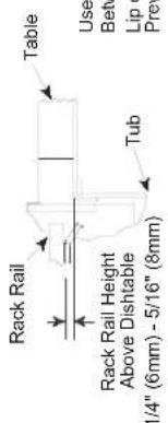
Recommended Table Fabrication
(五) 2017年
[Non-Text]
[Non-Text]
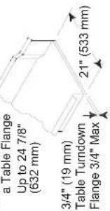
Note: Tub Will Accept
Use Silicone Sealer
Between Table and
Lip of Machine to Prevent Leakage
tion
Note: Tub Will Accept a Table Flange
Up to 24 7/8" (632 mm)
Use Silicone Sealer
Between Table and
Lip of Machine to
Prevent Leakage
3/4" (19 mm)
Table Turndown
Flange 3/4" Max
21" (533 mm)
Recommended Table Fabrication
![8³/4 [222mm] 11³/4 [298mm] 30 [763mm] 14 [357mm] 7¹/4 [185mm] 1¹/4 [35mm] 6 [152mm] -14³/4 [375mm] -20³/4 [527mm] H G J K A B 64 [1626mm] Table to Table 72 [1829mm] 80 [2032mm] Overall Floor Sink Or Drain With 3" (76 mm) Minimum Drain Line 21 [535mm] 25 [637mm] 8 [204mm] 4" (102 mm) wide x 16" (406 mm) long cutout in Vent Cowl/Splash Shield. Shipped with Cover Plate.](/content/2026/05/993820/images/0d3621f01d1a91781e7634fd62a8734c1d32b8642a288e36a9ffc2d490bc0831.jpg)
SECTION 1: SPECIFICATION INFORMATION
![Right to Left Legend A - Machine water inlet 3/4" NPT 180°F Hi-temp,140°F Low-temp minimum B - Electrical connection C - Drain connection 1-1/2" NPT D - Vent collar - Optional E - Vent cowl standard F - 3/4" NPT Steam connection G - 3/4" NPT Condensate return H - Steam electrical connection J - 1" NPT Steam connection K - 3/4" Condensate connection L - 3/4" NPT Incoming 110°F water connection M - 3/4" NPT 180°F water to dishmachine. Recommended Table Fabrication Note: Tub Will Accept a Table Flange Up to 24 7/8" (632 mm) 3/4" (19 mm) Table Turndown Flange 3/4" Max 21" (533 mm) 6 1/4 [159mm] 38 [966mm] 11 1/4 [285mm] K F M H L J L 6 1/4 [218mm] 5 3/4 [148mm] 4 1/4 [110mm] 13 1/2 [345mm] 23 3/4 [604mm] A B 64 [1626mm] Table to Table 72 [1829mm] 80 [2032mm] Overall Floor Sink Or Drain With 3" (76 mm) Minimum Drain Line 84 [2134mm] With Doors Open 66 1/2 [1692mm] 1 [25mm] A 1/2 [15mm] Rear of Machine Drive Unit 75 1/2 [1915mm] 62 1/2 [1588mm] 60 1/4 [1530mm] 4 [102mm] 35 [891mm] 24 1/2 [622mm] 8 [203mm] B 7 [178mm] D E 25 [635mm] Dish Clearance 65 1/2 [1665mm] 6 1/2 [162mm] 11 1/2 [295mm] 15 3/4 [400mm] 16 1/2 [417mm] 4" (102 mm) wide x 16" (406 mm) long cutout in Vent Cowl/Splash Shield. Shipped with Cover Plate. Drive Unit 6 1/2 [165mm] 32 3/4 [833mm] 5 [127mm] C 8 1/2 [218mm] Front View Left Side Right Side](/content/2026/05/993820/images/1c3b9ffcb7da3a601d258060f1a7ed279d631a87b40c863128527a72e00b388c.jpg)
![Recommended Table Fabrication Note: Tub Will Accept a Table Flange Up to 24 7/8" [632 mm] 3/4" [19 mm] Table Turndown Flange 3/4" Max 21" [533 mm] 16¹ [415mm] 16³ [425mm] F G Prewash Plan View Section with Cold Water Thermostat Rack Rail Height Above Dishtable 1/4" [6mm] - 5/16" [8mm] Tub Use Silicone Sealer Between Table and Lip of Machine to Prevent Leakage 14 [355mm] Minimum 21 [533mm] 25 [635mm] Scrap Trough 4" (102 mm) wide x 16" (406 mm) long cutout in Vent Cowl/Splash Shield. Shipped with Cover Plate. 8 [203mm] A 64 [1626mm]22 [559mm] Base Unit Prewash 86 [2184mm] Table to Table 94 [2388mm] 102 [2591mm] Overall Floor Sink Or Drain With 3" (76 mm) Minimum Drain Line 84 [2134mm] With Doors Open 66¹ [1692mm] 1 [25mm] F G A 65½ [1666mm] ½ [15mm] Rear of Machine Drive Unit 6 [152mm] Left Side Front View C 32³ [833mm] 10³ [260mm] 6 [152mm] 29 [737mm] 10 [254mm] 6 [152mm] 25 [635mm] 21 [533mm] 12 [307mm] 65½ [1665mm] 34 [864mm] C 8² [218mm] Right Side](/content/2026/05/993820/images/70291a92f90c01386dfad08b97d0c4529b3f400869fa9a91469582601a1759df.jpg)
SECTION 1: SPECIFICATION INFORMATION
AJ-86 GAS - LEFT TO RIGHT
Left to Right
![Legend A - Machine water inlet 3/4" NPT,110°F - 140°F Hi-temp,140°F Low-temp minimum B - Electrical connection C - Drain connection 1-1/2" NPT D - Vent collar - Optional E - Vent cowl standard F - 3/4" NPT 180°F Water Inlet for wash tank fill, final rinse, & tank heating. From gas booster heater. Interconnecting hose provided by manufacturer. G - 3/4" NPT 140°F Water inlet for gas booster heater. H - 3/4" NPT 180°F Water Outlet connection to line on dishmachine. Connection hose provided by manufacturer. J - 3/4" NPT Gas Connection K - 4" OD Vent pipe connection. Flue to be installed to meet local codes by installing contractor. L - Prewash water inlet 3/4" NPT 110°F-140°F M - Cold water thermostat plumbing connection 3/4" NPT - Optional Note: All vertical dimensions are +/- 1/2" from floor due to adjustable bullet feet. Recommended Table Fabrication Rack Rail Rack Rail Height Above Dishtable 1/4" [6mm] - 5/16" [8mm] Table Use Silicone Sealer Between Table and Lip of Machine to Prevent Leakage Note: Tub Will Accept a Table Flange Up to 24 7/8" [632 mm] 3/4" [19 mm] Table Turndown Flange 3/4" Max 21" [533 mm] 14 [355mm] Minimum 14 [357mm] 6 [154mm] 1½ [35mm] 7½ [185mm] 30 [763mm] 8³ [222mm] 11¾ [298mm] 14½ [375mm] 20³ [527mm] 21 [533mm] 25 [635mm] 22 [559mm] Prewash Base Unit 41 [1040mm] 86 [2184mm] Table to Table 94 [2388mm] Floor Sink Or Drain With 3" (76 mm) Minimum Drain Line Scrap Trough 4" (102 mm) wide x 16" (406 mm) long cutout in Vent Cowl/Splash Shield. Shipped with Cover Plate. Overall 84 [2134mm] With Doors Open 66½ [1692mm] A L M B 65½ [1666mm] 75½ [1918mm] 4 [102mm] L A B 2½ [61mm] 62½ [1590mm] 10" High Table Backsplash Drive Unit Scrap Trough 14 [356mm] Minimum 32¾ [833mm] 5½ [140mm] C 6 [152mm] 29 [737mm] 10 [254mm] 6 [152mm] Left Side Front View Right Side B 25 [635mm] 21 [533mm] 12 [307mm] 1 [25mm] A 25 [635mm] Dish Clearance 36 [914mm] 6 [152mm] H G J K C 8½ [218mm]](/content/2026/05/993820/images/6c2d9568e938edaf75af5c0ba5f7f47b8cf162ba5b6e6202c1e35368a663cd76.jpg)
Left to Right
![Legend A - Machine water inlet 3/4" NPT, 180°F Hi-temp,140°F Low-temp minimum B - Electrical connection C - Drain connection 1-1/2" NPT D - Vent collar - Optional E - Vent cowl standard F - 3/4" NPT 180°F Water Inlet for wash tank fill, final rinse, & tank heating. From gas booster heater. Interconnecting hose provided by manufacturer. G - 3/4" NPT 140°F Water inlet for gas booster heater. H - 3/4" NPT 180°F Water Outlet connection to line on dishmachine. Connection hose provided by manufacturer. J - 3/4" NPT Gas Connection K - 4" OD Vent pipe connection. Flue to be installed to meet local codes by installing contractor. L - Prewash water inlet 3/4" NPT 110°F-140°F M - Cold water thermostat plumbing connection 3/4" NPT - Optional Note: All vertical dimensions are +/- 1/2" from floor due to adjustable bullet feet. Recommended Table Fabrication Rack Rail Height Above Dishtable 1/4" [6mm] - 5/16" [8mm] Table Use Silicone Sealer Between Table and Lip of Machine to Prevent Leakage Note: Tub Will Accept a Table Flange Up to 24 7/8" [632 mm] 3/4" [19 mm] Table Turndown Flange 3/4" Max 21" [533 mm] 14 [355mm] Minimum 14 [357mm] 6 [154mm] 1½ [35mm] 7¼ [185mm] 30 [763mm] 8³ [222mm] 11½ [298mm] 14½ [375mm] 20³ [527mm] F H G J K Floor Sink Or Drain With 3" (76 mm) Minimum Drain Line Scrap Trough 4" (102 mm) wide x 16" (406 mm) long cutout in Vent Cowl/Splash Shield. Shipped with Cover Plate. Prewash 86 [2184mm] Table to Table 94 [2388mm] 102 [2591mm] Overall 84 [2134mm] With Doors Open 66½ [1692mm] A L M B 65½ [1666mm] 75½ [1918mm] L M B 4 [102mm] L A B 2½ [61mm] 62½ [1590mm] Drive Unit Rear of Machine Drive Unit 6 [152mm] 10 [254mm] 6 [152mm] 14 [356mm] Minimum 32¾ [833mm] C 5½ [140mm] 29 [737mm] 6½ [165mm] 25 [635mm] 21 [533mm] 12 [307mm] 1 [25mm] A B D E E 31½ [795mm] 26½ [673mm] 36 [914mm] H G J K Dish Clearance 34 [864mm] C 8½ [218mm] Left Side Front View Right Side](/content/2026/05/993820/images/255e5b646d715117320f7c4bd487c6ad95f2597d7de64f7d7a45bdfa3a27ce42.jpg)
SECTION 1: SPECIFICATION INFORMATION
AJ-86 GAS - RIGHT TO LEFT
Right to Left
![Legend to Drawing A - Machine water inlet 3/4" NPT, 110°F - 140°F Hi-temp, 140°F Low-lemp minimum B - Electrical connection C - Drain connection 1-1/2" NPT D - Vent collar - Optional E - Vent cowl standard F - 3/4" NPT 180°F Water Inlet for wash tank fill, final rinse, & tank heating. From gas booster heater. Interconnecting hose provided by manufacturer. G - 3/4" NPT 140°F Water inlet for gas booster heater. H - 3/4" NPT 180°F Water Outlet connection to line on dishmachine. Connection hose provided by manufacturer. J - 3/4" NPT Gas Connection K - 4" OD Vent pipe connection. Flue to be installed to meet local codes by installing contractor. L - Prewash water inlet 3/4" NPT 110°F-140°F M - Cold water thermostat plumbing connection 3/4" NPT - Optional Note: All vertical dimensions are +/- 1/2" from floor due to adjustable bullet feet. Recommended Table Fabrication Rack Rail Rack Rail Height Above Dishtable 1/4" [6mm] - 5/16" [8mm] Table Use Silicone Sealer Between Table and Lip of Machine to Prevent Leakage Note: Tub Will Accept a Table Flange Up to 24 7/8" [632 mm] 3/4" [19 mm] Table Turndown Flange 3/4" Max 21" [533 mm] Prewash Plan View Section with Cold Water Thermostat 8³ [222mm] 11³ [298mm] 30 [763mm] 14 [357mm] 7¹ [185mm] 6 [152mm] 14³ [375mm] 20³ [527mm] H G J K 4" (102 mm) wide x 16" (406 mm) long cutout in Vent Cowl/Splash Shield. Shipped with Cover Plate. A B 64 [1626mm] Base Unit 22 [557mm] Prewash Floor Sink Or Drain With 3" (76 mm) Minimum Drain Line 102 [2589mm] Overall 8 [204mm] 21 [535mm] 25 [637mm] 8 [204mm] 64 [1626mm] Base Unit 22 [557mm] Prewash Floor Sink Or Drain With 3" (76 mm) Minimum Drain Line 75² [1919mm] 8 [203mm] 4 [102mm] 47 [1194mm] 43 [1092mm] 62² [1590mm] 60² [1530mm] A B L 24 [610mm] 23² [599mm] 31½ [797mm] 26½ [673mm] 6 [155mm] 36 [914mm] H G J K Drive Unit 6² [165mm] 6² [165mm] 53³ [1365mm] C 10 [254mm] 10½ [261mm] 6 [152mm] 34 [864mm] B 25 [635mm] 21 [533mm] 12 [307mm] 65½ [1665mm] Right Side C 8² [217mm] Left Side 66½ [1692mm] 1 [25mm] 3 [79mm] A L M Rear of Machine Drive Unit](/content/2026/05/993820/images/c5bc1864c0071a932e5eac7ab78db5941253bfdb226875415e9bec9d21fd8b35.jpg)
SECTION 1: SPECIFICATION INFORMATION
SECTION 1: SPECIFICATION INFORMATION
SECTION 1: SPECIFICATION INFORMATION
SECTION 1: SPECIFICATION INFORMATION
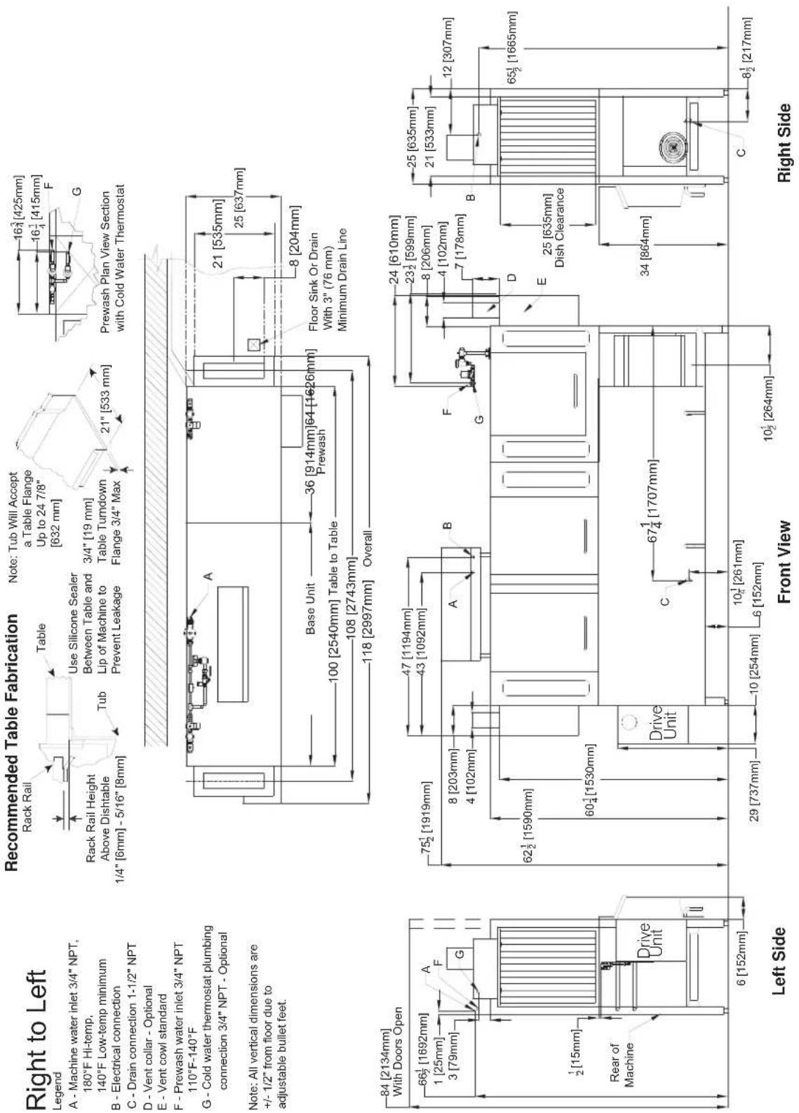
Prewash Plan View Section with Cold Water Thermostat
Right to Left Legend
A - Machine water inlet 3/4" NPT,
180°F Hi-temp,
140°F Low-temp minimum
B - Electrical connection
C - Drain connection 1-1/2" NPT
D - Vent collar - Optional
E - Vent cowl standard
F - Prewash water inlet 3/4" NPT
110°F-140°F
Cold water thermostat plumbing
connection 3/4" NPT - Optional
Note: All vertical dimensions are
+/- 1/2" from floor due to
adjustable bullet feet.
SECTION 1: SPECIFICATION INFORMATION
AJ-100 GAS - LEFT TO RIGHT
![Recommended Table Fabrication Note: Tub Will Accept a Table Flange Up to 24 7/8" [632 mm] 16³/4 [425mm] 16³/4 [415mm] L M Prewash Plan View Section with Cold Water Thermostat 30 [763mm] 14 [357mm] 6 [154mm] 1¼ [35mm] 8³/4 [222mm] 11³/4 [298mm] 14³/4 [375mm] 20³/4 [527mm] G - 3/4" NPT 180°F Water Inlet for wash tank fill, final rinse, & tank heating. From gas booster heater. Interconnecting hose provided by manufacturer. G - 3/4" NPT 140°F Water inlet for gas booster heater. H - 3/4" NPT 180°F Water Outlet connection to line on dishmachine. Connection hose provided by manufacturer. J - 3/4" NPT Gas Connection K - 4" OD Vent pipe connection. Flue to be installed to meet local codes by installing contractor. L - Prewash water inlet 3/4" NPT 110°F-140°F M - Cold water thermostat plumbing connection 3/4" NPT - Optional Note: All vertical dimensions are +/- 1/2" from floor due to adjustable bullet feet. 84 [2134mm] With Doors Open 66½ [1692mm] 65½ [1666mm] 1 [25mm] A ½ [15mm] Rear of Machine Drive Unit 6 [152mm] Left Side Front View C 32³/4 [833mm] 29 [737mm] 10 [254mm] 6 [152mm] 10½ [267mm] 6 [165mm] Right Side 25 [635mm] 21 [533mm] 12 [307mm] 65½ [1665mm] 34 [864mm] C 8½ [218mm]](/content/2026/05/993820/images/a35e2369ebe9b88fe21436fab52707cc81217b1988ad796007652a4ddc0ce41b.jpg)
SECTION 1: SPECIFICATION INFORMATION
AJ-100 GAS - RIGHT TO LEFT
Right to Left

![8³ [222mm] 11³ [298mm] 30 [763mm] 14 [357mm] 7¹ [185mm] 1¹ [35mm] 6 [152mm] 8 [203mm] 14³ [375mm] 20³ [527mm] H G J K from 4" (102 mm) wide x 16" (406 mm) long cutout in Vent Cowl/Splash 64 [1626mm] Base Unit 36 [914mm] Prewash 100 [2540mm] Table to Table 108 [2743mm] 118 [2997mm] Overall Floor Sink Or Drain With 3" (76 mm) Minimum Drain Line 21 [535mm] 25 [637mm] 8 [204mm]](/content/2026/05/993820/images/15fd58b6081b9f0ea2c8dfe8c91ba6b3fee7e66905c2a8a6a7ea5b7f199941de.jpg)
![84 [2134mm] With Doors Open 66½ [1692mm] 1 [25mm] 3 [79mm] A L M Rear of Machine ½ [15mm] Drive Unit 6 [152mm] Left Side 75½ [1919mm] 62½ [1590mm] 8 [203mm] 4 [102mm] 60½ [1530mm] 31½ [797mm] 26½ [673mm] 36 [914mm] 6 [152mm] H G J K Drive Unit 6½ [165mm] 67¼ [1707mm] 10 [254mm] 10¼ [261mm] 6 [152mm] Front View 62½ [152mm] 47 [1194mm] 43 [1092mm] A B L M D E 25 [635mm] 21 [533mm] 24 [610mm] 23½ [599mm] 8 [206mm] 4 [102mm] 7 [178mm] B D E 25 [635mm] Dish Clearance 34 [864mm] Right Side C 8½ [218mm]](/content/2026/05/993820/images/b020ff2224667e611b8cb5533d67debff1007f00ff086d32d7a83075d620cd78.jpg)
A - Machine water inlet 3/4" NPT, 110°F - 140°F Hi-temp, 140°F Low-temp minimum
B - Electrical connection C - Drain connection 1-1/2" NPT
D - Vent collar - Optional
E - vent cowl standard F - 3/4" NPT 180°F Water Inlet for wash tank fill, final rinse, & tank heating. From gas booster heater. Interconnecting hose provided by manufacturer. G - 3/4" NPT 140°F Water inlet for
gas booster heater. H - 3/4" NPT 180°F Water Outlet connection to line on dishmachine. Connection hose provided by manufacturer.
J - 3/4" NPT Gas Connection K - 4" OD Vent pipe connection. Flue to be installed to meet local codes by installing contractor. L - Prewash water inlet 3/4" NPT 110°F-140°F M - Cold water thermostat plumbing connection 3/4" NPT - Optional
Note: All vertical dimensions are +/- 1/2" from floor due to adjustable bullet feet.
84 [2134mm] With Doors Op
![66½ [1692mm] 1 [25mm] 3 [79mm] A L M ½ [15mm] Rear of Machine Drive Unit U 6 [152mm]](/content/2026/05/993820/images/be67d4fa0ee3f024eadeb38b9ad668f6b14fc9321bd131e76c5d7c8e29309fce.jpg)
![Left to Right Recommended Table Fabrication Legend A - Machine water inlet 3/4" NPT 180°F Hi-temp,140°F Low-temp minimum B - Electrical connection C - Drain connection 1-1/2" NPT D - Vent collar - Optional E - Vent cowl standard F - 3/4" NPT Steam connection G - 3/4" NPT Condensate return H - Steam electrical connection J - 1" NPT Steam connection K - 3/4" Condensate connection L - 3/4" NPT Incoming 110°F water connection M - 3/4" NPT 180°F water to dishmachine. N - Prewash water inlet 3/4" NPT 110°F-140°F O - Cold water thermostat plumbing connection 3/4" NPT - Optional Note: All vertical dimensions are +/- 1/2" from floor due to adjustable bullet feet. Recommended Table Fabrication Note: Tub Will Accept a Table Flange Up to 24 7/8" [632 mm] 3/4" [19 mm] Table Tumdown Flange 3/4" Max 21" [533 mm] Prewash Plan View Section with Cold Water Thermostat 16½ [425mm] 16½ [415mm] N O 21 [533mm] 25 [635mm] 8 [203mm] Scrap Trough 4" (102 mm) wide x 16" (406 mm) long cutout in Vent Cowl/Splash Shield. Shipped with Cover Plate. 36 [914mm] 64 [1626mm] Base Unit 100 [2540mm] Table to Table 108 [2743mm] Overall Floor Sink Or Drain With 3" (76 mm) Minimum Drain Line 84 [2134mm] With Doors Open 66½ [1692mm] 65½ [1666mm] 1 [25mm] N A ½ [15mm] Rear of Machine Drive Unit 6 [152mm] 75½ [1918mm] 62½ [1590mm] 60½ [1529mm] 10° High Table Backsplash Drive Unit 29 [737mm] 10 [254mm] 6 [152mm] 10½ [264mm] 14 [356mm] Minimum 10½ [260mm] 6 [152mm] 10³ [833mm] 32½ [833mm] 10 [255mm] G C F L H J M 17½ [442mm] 43 [1092mm] 6½ [162mm] 11½ [295mm] 15¾ [400mm] 16½ [417mm] Right Side 8½ [218mm]](/content/2026/05/993820/images/6d8678490ce4651e33753ff31d00e87be56596563be0626c60407573e511a422.jpg)
SECTION 1: SPECIFICATION INFORMATION
SECTION 1: SPECIFICATION INFORMATION
SIDE LOADER (RIGHT TO LEFT) DIMENSIONS
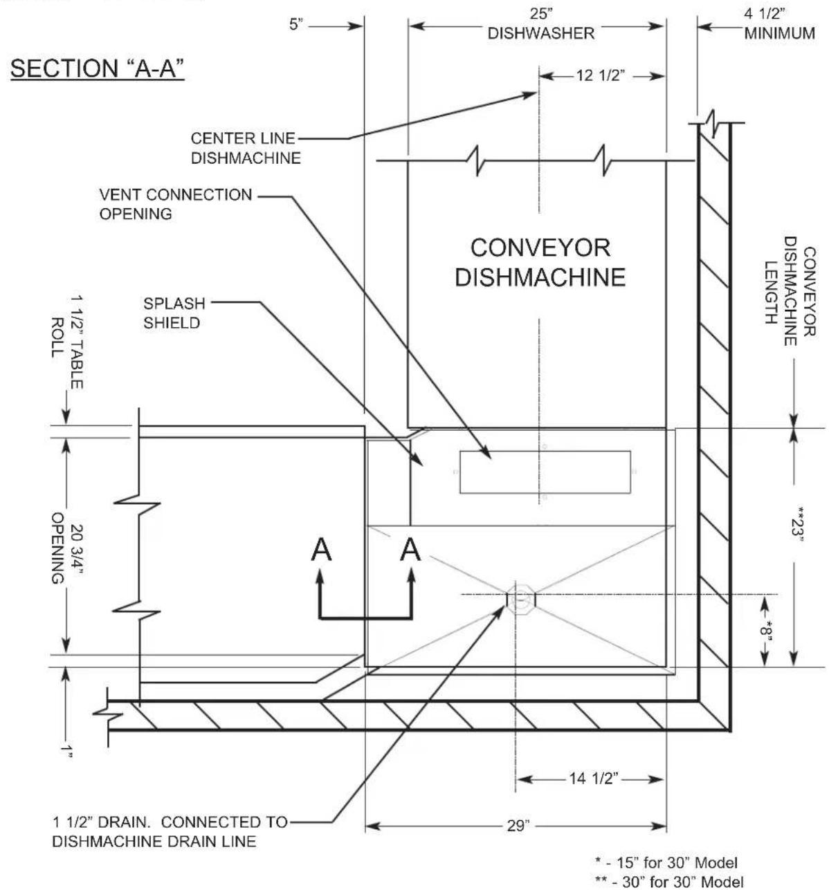
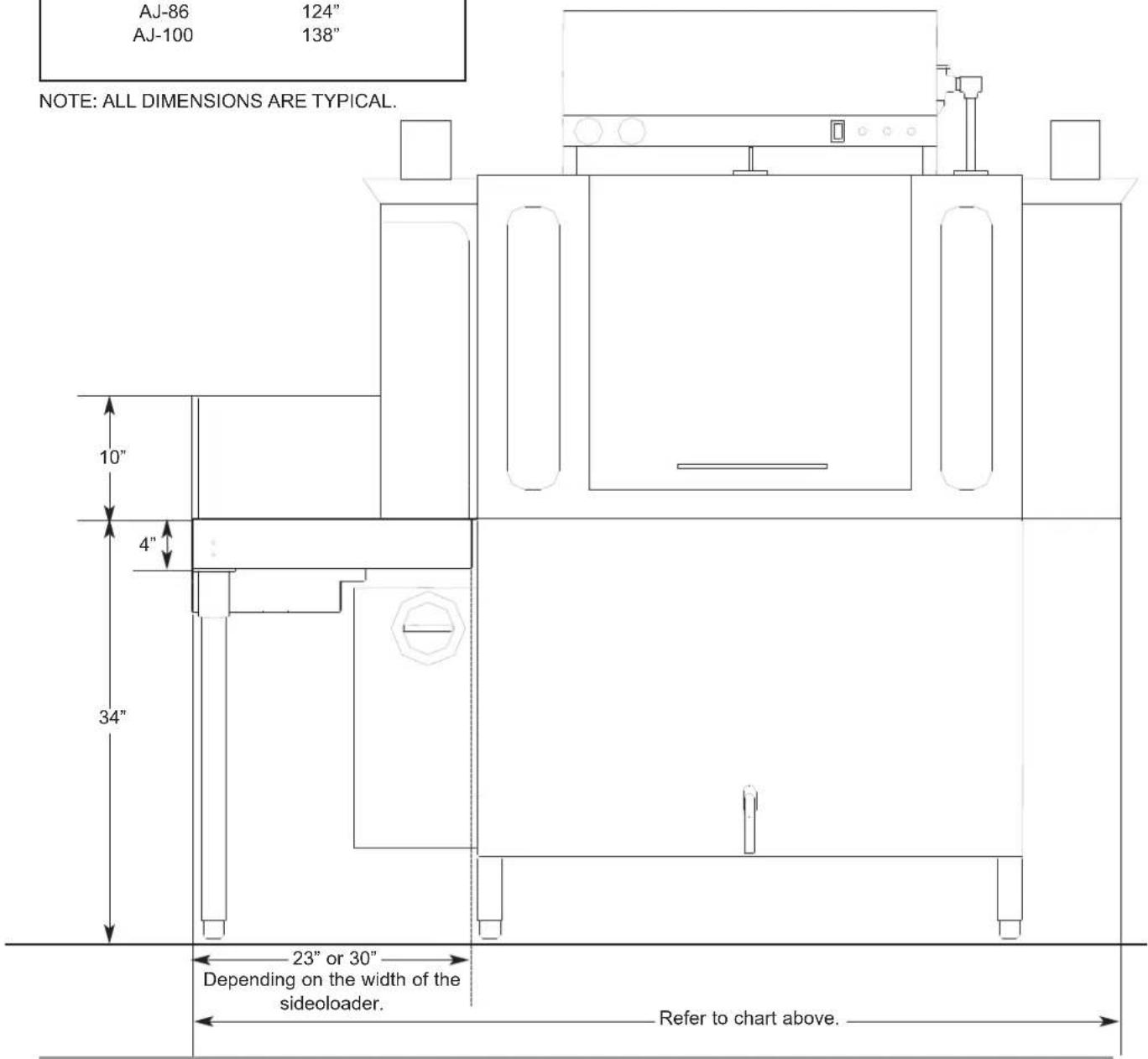
SECTION 1: SPECIFICATION INFORMATION SIDE LOADER INSTALLATION DIMENSIONS
| 23” SIDE LOADER DIMENSIONS | |
| MODEL | DIMENSIONS |
| AJ-64 | 95" |
| AJ-86 | 117" |
| AJ-100 | 131" |
| 30” SIDE LOADER DIMENSIONS | |
| MODEL | DIMENSIONS |
| AJ-64 | 102" |
| AJ-86 | 124" |
| AJ-100 | 138" |
NOTE: ALL DIMENSIONS ARE TYPICAL.
(Left to Right installation shown for reference.)
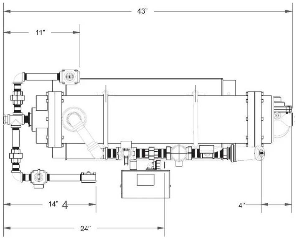
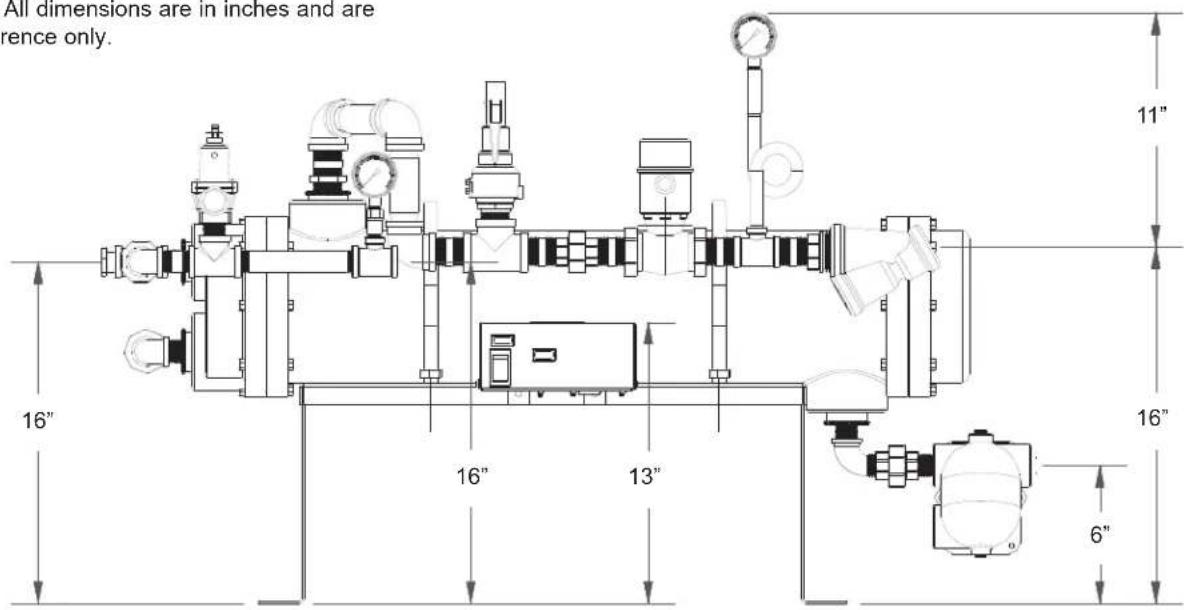
SECTION 1: SPECIFICATION INFORMATION D226 STEAM BOOSTER DIMENSIONS
NOTE: All dimensions are in inches and are for reference only.
SECTION 1: SPECIFICATION INFORMATION
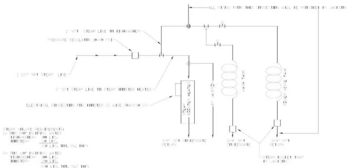
D226 STEAM BOOSTER PLUMBING LINE DRAWINGS
flowchart
graph TD
    A["1/2" NFT STEAM LINE"] --> B["Pressure Regulation 0-20 PS"]
    B --> C["2" NFT STEAM LINE TO STEAM HODSTER HEATER"]
    C --> D["ELECTRICAL CONNECTION FOR HODSTER (2 WIRE 200-250 V)"]
    D --> E["3/4" NET COMPENSATE RETURN"]
    E --> F["2/4" NET INLEVATE"]
    F --> G["3/4" NET RETURN"]
    G --> H["STEAM SWITCH TRAP BY SWITCH"]
    I["ALL FEING FROM THIS CONNECTION WILL BE PRODUCED BY JACKSON"] --> J["Ground"]
    K["STEAM VOLTAGE PARAMETERS"] --> L["1- FOR 100° FEOD RATE WATER\nEARTH/ASHER- 200 LFS,\nHOTU-TE- 100 LFS,\n2.0 LFS, 10L, 6.5 LFS"]
    L --> M["2- FOR 20° INCOATING WATER\nEARTH/ASHER- 200 LFS,\nHOTU-TE- 100 LFS,\n2.0 LFS, 10L, 6.5 LFS"]
PLINTER TO CONNECT ALL CONENSATE RETURNS TO OTHER FROM OR TO CONENSATE RETURN LINE
Steam Booster Piping - Double Tank Machine
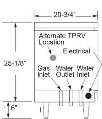
SECTION 1: SPECIFICATION INFORMATION TYPICAL ELECTRIC AND GAS BOOSTER DIMENSIONS
Electric Booster Dimensions (Typical)
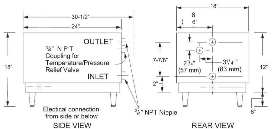
LEFT SIDE VIEW
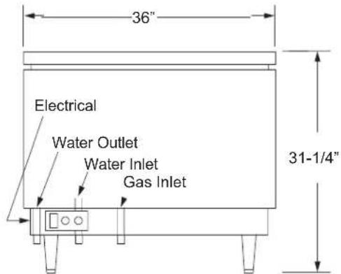
FRONT VIEW
Gas Booster Dimensions (Typical)
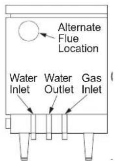
RIGHT SIDE VIEW

REAR VIEW
SECTION 2: INSTALLATION/OPERATION INSTRUCTIONS
SECTION 2: INSTALLATION/OPERATION INSTRUCTIONS
INSTALLATION INSTRUCTIONS

NOTE: THE INSTRUCTIONS PROVIDED HEREIN, UNLESS OTHERWISE SPECIFIED ARE FOR THE DISHMA-CHINES ONLY. THERE ARE SEPARATE DIRECTIONS FOR THE GAS BOOSTER.
VISUAL INSPECTION: Before installing the unit, check the container and machine for damage. A damaged container is an indicator that there may be some damage to the machine. If there is damage to both the container and machine, do not throw away the container. The dishmachine has been inspected and packed at the factory and is expected to arrive to you in new, undamaged condition. However, rough handling by carriers or others may result in damage to the unit while in transit. If such a situation occurs, do not return the unit to Jackson; instead, contact the carrier and ask them to send a representative to the site to inspect the damage to the unit and to complete an inspection report. You must contact the carrier within 48 hours of receiving the machine. Also, contact the dealer through which you purchased the unit.
UNPACKING THE DISH MACHINE: The machine should be unboxed and removed from shipping pallet prior to being installed. Open the front door and remove all of the packing materials. Once unpacked, ensure that there are no missing parts from the machine. This may not be obvious at first. If it is discovered that an item is missing, contact Jackson immediately.
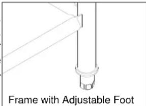
LEVEL THE DISH MACHINE: The dish machine is designed to operate while being level. This is important to prevent any damage to the machine during operation and to ensure the best results when washing ware. The unit comes with adjustable bullet feet, which can be turned using a pair of channel locks or by hand if the unit can be raised safely. Ensure that the unit is level from side to side and from front to back before making any connections. You will be able to adjust the overall height of the unit by turning the bullet feet from between 75-1/2" to 76-1/2".
PLUMBING THE DISH MACHINE: All plumbing connections must comply with all applicable local, state, and national plumbing codes. The plumber is responsible for ensuring that the incoming water line is thoroughly flushed prior to connecting it to any component of the dishmachine. It is necessary to remove all foreign debris from the water line that may potentially get trapped in the valves or cause an obstruction. Any valves that are fouled as a result of foreign matter left in the water line, and any expenses resulting from this fouling, are not the responsibility of the manufacturer.
Water hardness should be a maximum of 6 grains per gallon. Harder water should be treated prior to using the machine. Iron in the water supply can cause staining. A filter designed to remove iron from the supply water is highly recommended for supplies in excess of 0.1 ppm (parts per million).
CONNECTING THE DRAIN LINE: The drain for the models covered in this manual are gravity discharge drains. All piping from the machine to the drain must be a minimum 1 1/2" NPT and should not be reduced. There must also be an air gap between the machine drain line and the floor sink or drain. If a grease trap is required by code, it should have a flow capacity of 30 gallons per minute.
WATER SUPPLY CONNECTION: Ensure that you have read the section entitled "PLUMBING THE DISH MACHINE" above before proceeding. It is also recommended that a pressure regulator (not supplied) be installed in the incoming water line. The supply water temperature must meet the minimum requirements listed on the machine data plate. Install the water supply line (3/4" pipe size minimum) to the dishmachine line strainer. It is recommended that a water shut-off valve be installed in the water line between the main supply and the machine to allow access for service. The water supply line is to be capable of 25 PSI "flow" pressure at the recommended temperature indicated on the data plate.
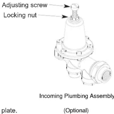
If the water level is too low or too high, check the incoming water pressure. It should be 20 ± 5 PSI. Too high of pressure results in too much water; too low of pressure results in too little water. To adjust the regulator, loosen the nut at the top, this will allow you to screw or unscrew the adjustment. With a screwdriver, turn the adjuster clockwise to increase pressure or counter clockwise to decrease it.
Do not confuse static pressure with flow pressure. Static pressure is the line pressure in a “no flow” condition (all valves and services are closed). Flow pressure is the pressure in the fill line when the fill valve is opened during the cycle.
It is also recommended that a shock absorber (not supplied) be installed in the incoming water line. This prevents line hammer (hydraulic shock), induced by the solenoid valve as it operates, from causing damage to the equipment.
SECTION 2: INSTALLATION/OPERATION INSTRUCTIONS INSTALLATION INSTRUCTIONS (CONTINUED)
STEAM LINE CONNECTIONS: Some machines covered in this manual are designed to use low pressure steam as a source of heat for wash tank water. The machines come with lines by which outside source steam needs to be connected. Connect all incoming steam lines in accordance with the steam booster manufacturer's instructions. Ensure that all applicable codes and regulations are adhered to. See machine data plate for information concerning steam flow pressure.
GAS CONNECTIONS: Some machines covered in this manual are designed to use gas as an outside source of heat for wash tank water. The machines come with connections by which an outside source needs to be connected. Connect all incoming gas lines in accordance with the gas booster manufacturer's instructions. Ensure that all applicable codes and regulations are adhered to.
PLUMBING CHECK: Slowly turn on the water supply to the machine after the incoming fill line and the drain line have been installed. Check for any leaks and repair as required. All leaks must be repaired prior to placing the machine in operation.
ELECTRICAL POWER CONNECTION: Electrical and grounding connections must comply with the applicable portions of the National Electrical Code ANSI/NFPA 70 (latest edition) and/or other electrical codes.
Disconnect electrical power supply and place a tag at the disconnect switch to indicate that you are working on the circuit.
The dishmachine data plate is located on the right side and to the front of the machine. Refer to the data plate for machine operating requirements, machine voltage, total amperage load and serial number.
To install the incoming power lines, open the control box. Install conduit into the pre-punched holes in the back of the control box. Route power wires and connect to power block and grounding lug. Install the service wires (L1, L2, and L3 (3 phase only)) to the appropriate terminals as they are marked on the terminal block. Install the grounding wire into the lug provided. Tighten the connections. It is recommended that "DE-OX" or another similar anti-oxidation agent be used on all power connections.
VOLTAGE CHECK: Ensure that the power switch is in the OFF position and apply power to the dishmachine. Check the incoming power at the terminal block and ensure it corresponds to the voltage listed on the data plate. If not, contact a qualified service agency to examine the problem. Do not run the dishmachine if the voltage is too high or too low. Shut off the service breaker and mark it as being for the dishmachine. Advise all proper personnel of any problems and of the location of the service breaker. Replace the control box cover and tighten down the screws.
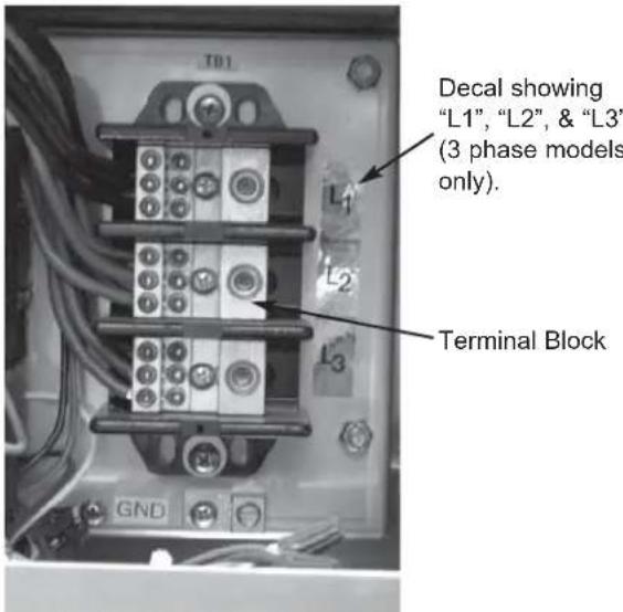
Incoming Power Connection
VENTILATION OF DISH MACHINE: The dishmachine should be located with provisions for venting into an adequate exhaust hood or ventilation system. This is essential to permit efficient removal of the condensation exhaust. Ensure that the exhaust system is acceptable in accordance with all applicable codes and standards.
NOTE: Any damage that is caused by steam or moisture due to improper ventilation is NOT covered under the warranty.
This units covered in this manual have the following exhaust requirements:
Load End: 200 CFM
Unload End: 400 CFM
The exhaust system must be sized to handle this volume for the dishmachine to operate as it was designed to.
SECTION 2: INSTALLATION/OPERATION INSTRUCTIONS
INSTALLATION INSTRUCTIONS (CONTINUED)
ELECTRIC HEAT: The thermostats for the machines covered in this manual are factory set. They should not be adjusted except by an authorized service agent.
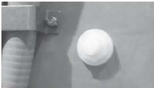
CHEMICAL FEEDER EQUIPMENT: Detergent may be introduced into the unit through the removal of the bulkhead plug in the rear of the tub and replacing it with the third party detergent injection fitting. Remove the bulkhead plug in the side of the tub to install the detergent concentration probe.
For more information concerning detergent concerns, please refer to the page entitled "Detergent Control".
natural_image
Close-up of a white spherical object with a textured surface and a small metallic bracket (no text or symbols visible)Detergent Connection Point (Machine rear view)
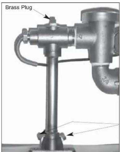
The 1/8" brass plugs on the incoming plumbing rinse injector may be removed to install rinse aid injection fittings.
Brass Plugs
natural_image
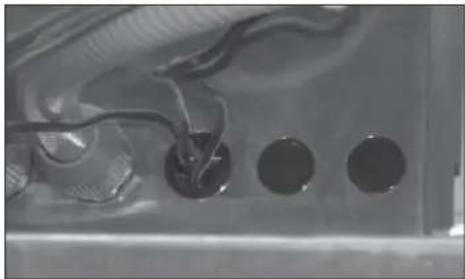
Close-up of a mechanical component with four circular holes and wiring (no visible text or symbols)All wires for the chemical injectors should be routed through one of the extra openings in the back of the control box.
natural_image
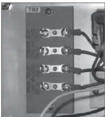
Close-up of an electronic control panel with four leads and wiring (no visible text or symbols)Connection Points
Terminals in the control box marked "CVS" provide a constant voltage signal whenever the drive motor is operating.
Terminals in the control box marked "DET" provide a voltage signal whenever the wash motor is operating.
SECTION 2: INSTALLATION/OPERATION INSTRUCTIONS
DELIMING OPERATIONS
DELIMING OPERATIONS: In order to maintain the dishmachine at its optimum performance level, it will be required to remove lime and corrosion deposits on a frequent basis. A deliming solution should be available from your detergent supplier. Read and follow all instructions on the label of the deliming solution.
To proceed with the deliming operation, fill the dishmachine and add the correct amount of deliming solution as recommended by the deliming solution manufacturer. The water capacity of the various tanks of the dishmachine can be verified on the specification sheet(s) of this manual.
Perform the following operations to deline the dishmachine:
- Turn the AUTOMATIC/DELIME switch on the back of the control box to the DELIME position.
- Disconnect or turn off all chemical feeder pumps.
- Close all doors (after adding the delimming solution).
- Run the machine for the recommended period of time.
- Turn the unit off and open the doors.
- Wait five minutes, then inspect the inside of the machine. If the machine is not delimited, run another time cycle as per the deliming solution's instructions.
- When clean, drain and re-fill the machine.
- Run in MANUAL for 10 minutes to remove residual deliming solution.
- Drain and re-fill the machine.
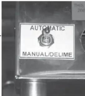
Delime Switch
This equipment is not recommend for use with deionized water or other aggressive fluids. Use of deionized water or other aggressive fluids will result in corrosion and failure of materials and components. Use of deionized water or other aggressive fluids will void the manufacturer's warranty.
SECTION 2: INSTALLATION/OPERATION INSTRUCTIONS
CURTAIN INSTALLATION DIAGRAMS
Please refer to the chart for placement of the curtains.
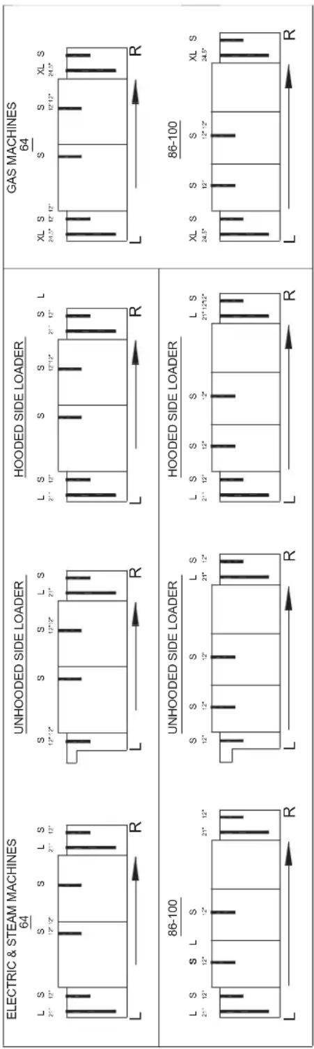
SECTION 2: INSTALLATION/OPERATION INSTRUCTIONS SIDE LOADER INSTALLATION & OPERATION INSTRUCTIONS
This accessory assists in the delivery of a full dish rack from the break down (scrapping) table to the dishmachine. It will convert the direction of travel 90°. Since the Side Loader is shipped mounted on the conveyor dishwasher there is no additional installation required for this option. As it is operated mechanically by the dishwasher it does not require any plumbing or electrical connections.
This Side Loader does not require or add any additional electrical or mechanical devices to the unit which could create operational or maintenance problems. As designed the drive mechanism is powered by the conveyor drive motor on the dishmachine. An extension on the pawl bar provides the drive to push the racks into the unit.
PREPARATION: Before proceeding with the start-up of the unit, verify that the Side Loader pan strainer is installed.
WARE PREPARATION: Proper preparation of ware will help ensure good results and less re-washes. If not done properly, ware may not come out clean and the efficiency of the dishmachine will be reduced. It is important to remember that a dishmachine is not a garbage disposal and that simply throwing unscraped dishes into the machine simply defeats the purpose altogether of washing the ware. Scraps should be removed from ware prior to being loaded into a rack. Pre-rinsing and pre-soaking are good ideas, especially for silverware and casserole dishes. Place cups and glasses upside down in racks so that they do not hold water during the cycle. The dishmachine is meant not only to clean, but to sanitize as well, to destroy all of the bacteria that could be harmful to human beings. In order to do this, ware must be properly prepared prior to being placed in the machine.
WASHING A RACK OF WARE: Once a rack is fully loaded it should be positioned against the front of the dish table. The rack should then be moved into the Side Loader until it activates the actuator switch. Once the machine is started, it should pull the rack through the machine and push it out the unload end. Once a rack has started through, you may put another rack in.
OPERATIONAL INSPECTION: Based upon usage, the pan strainer may become clogged with soil and debris as the workday progresses. Operators should regularly inspect the pan strainer to ensure it has not become clogged. If the strainer does become clogged, it will reduce the washing capability of the machine. Instruct operators to clean out the pan strainer at regular intervals or as required by work load.
SHUTDOWN AND CLEANING: At the end of the workday, remove the pan strainer and clean as required. Wipe out the inside of the Side Loader and then reinsert the strainer.
SECTION 2: INSTALLATION/OPERATION INSTRUCTIONS
D226 STEAM BOOSTER INSTALLATION & OPERATION INSTRUCTIONS
CONCEALED DAMAGE OR MISSING PARTS:

IMPORTANT: FOR YOUR PROTECTION, PLEASE READ AND OBSERVE THE FOLLOWING:
This steam booster has been thoroughly inspected and carefully packed before leaving our warehouse.
Concealed loss or damage means loss or damage which does not become apparent until the booster has been unpacked. The contents may be damaged in transit due to rough handling even though the carton may not show external damage.
If it is found that the shipment has concealed damage, PLEASE DO NOT RETURN IT TO JACKSON, but notify the carrier (within 48 hours) asking them to send their agent to fill out an inspection report. Save the cartons so he may inspect them and be sure to note in the report any black marks, creases, tears, crushed corners or any other marks indicating rough handling. Also, notify your JACKSON dealer immediately.
If it is discovered that there are missing parts, please notify your JACKSON dealer immediately.
EQUIPMENT MOUNTING:
Your booster should come pre-assembled and will require that it be permanently mounted in place. The platform has pre-punched holes to allow for mounting to the installation floor. NOTE: The D226 Booster must be properly mounted and level before being used. Once the platform is secure to the floor, attach the water and steam lines in accordance with local and national codes.
PLUMBING:
NOTE: ALL CONNECTIONS MUST COMPLY WITH ALL APPLICABLE LOCAL, STATE AND NATIONAL PLUMBING CODES.
The plumber is responsible for ensuring that the water line is THOROUGHLY FLUSHED BEFORE connecting it to any manual or solenoid valve. It is necessary to remove all foreign matter such as chips (resulting from cutting or threading pipes), pipe joint compound or, if soldered fittings are used, bits of solder or cuttings from the lines. This debris, if not removed, may lodge in the valves and render them inoperative.
The D226 Booster is designed to take incoming water from a minimum temperature of 110^ F to approximately 180^ F for use in the final rinse of your Jackson dishmachine. In order to do this, water is supplied to the booster and is heated by tubes carrying 15-25 PSIG flow steam. Heat is transferred from the steam into the water, raising the temperature.
Install condensate drains in accordance with applicable codes.
The D226 Booster is designed to operate at a water flow rate of 20 ± 5 PSI. The assembly comes with a water pressure regulator, which is preset at the factory. However, adjustment may be required so ensure that you verify the flow pressure before beginning operations. See the instructions regarding adjustment and maintenance of the water pressure regulator for more information.

WARNING: The D226 Booster is designed to heat water to a minimum of 180^ F and is extremely hot during operations. Advise personnel of the dangers associated with touching booster components as burns or severe injury can occur.

This equipment is not recommend for use with deionized water or other aggressive fluids. Use of deionized water or other aggressive fluids will result in corrosion and failure of materials and components. Use of deionized water or other aggressive fluids will void the manufacturer's warranty.
SECTION 2: INSTALLATION/OPERATION INSTRUCTIONS
D226 STEAM BOOSTER INSTALLATION & OPERATION INSTRUCTIONS (CONTINUED)
ELECTRICAL:

WARNING: Electrical and grounding connections must comply with applicable portions of the National Electrical Code ANSI / NFPA 70 (latest edition) and/or other electrical codes.Disconnect electrical power supply and place a tag or lock
at the disconnect switch to indicate that you are working on the circuit.
To connect the incoming power, run the conduit for power wires through the open hole in the back of the control box. Connect the power wires to the terminal block as it is labeled (L1 and L2). Run the ground wire to the grounding lug marked "GND". Tight connections and conduit nuts and close the control box by putting the cover on and securing with the 10-32 screws.
OPERATION:

WARNING: The heat exchanger used in the D226 Booster system is a pressure vessel with very precise operating parameters. Safety equipment such as valves should never be tampered with or disabled. These devices are meant to act the equipment and the operator from harm, damage and death.
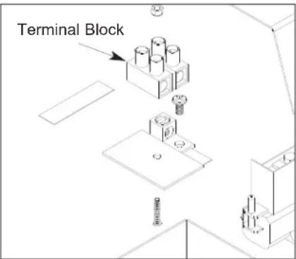
D226 Conrtol Box
- Ensure that water, steam and any condensate drains are connected to the booster.
- Start the water flow first, open the condensate drains and then begin steam flow.
- On the control box, press the power switch and put it in the ON position. The power light should illuminate.
The unit should run normally now.

WARNING: Do not shock the system by applying the steam before the water. This can cause damage to the booster.
The following explanation describes the operation of the D226 Booster.
NOTE: This explanation assumes that water and steam have been connected to the machine.
- When the power switch (S1) is placed in the ON position, power is provided to both the power light (E1) and the thermostat (TS1).
- The thermostat (TS1) will close when the water falls below the minimum setpoint, energizing the steam solenoid light (E2) and the steam solenoid (FS1).
- The steam solenoid (FS1) will remain open, allowing steam into the booster, until the water temperature reaches the desired temperature. At that point, the thermostat (TS1) will open, de-energizing the steam solenoid (FS1) and the steam solenoid light (E2).
IMPORTANT: Please remember that all of the components in the control box are under line voltage (208-240 volts). Under no circumstance is the control box cover to be removed or opened during normal operations!

SHUTDOWN (FOR SERVICE ONLY):

WARNING: The D226 Booster is designed to heat water to a minimum of 180^ F and is extremely hot during operations. Advise personnel of the dangers associated with touching booster components as burns or severe injury can occur.
- Turn the power switch to the OFF position. The power light should extinguish.
- Secure steam flow to the unit.
- Secure water flow.
- Close the condensate drains as required by procedure and/or code.
- Do not attempt to clean, wipe down or perform any maintenance on the booster until it has been given a generous amount of time to cool down.
SECTION 2: INSTALLATION/OPERATION INSTRUCTIONS
GAS CONVEYOR HOSE INSTALLATION
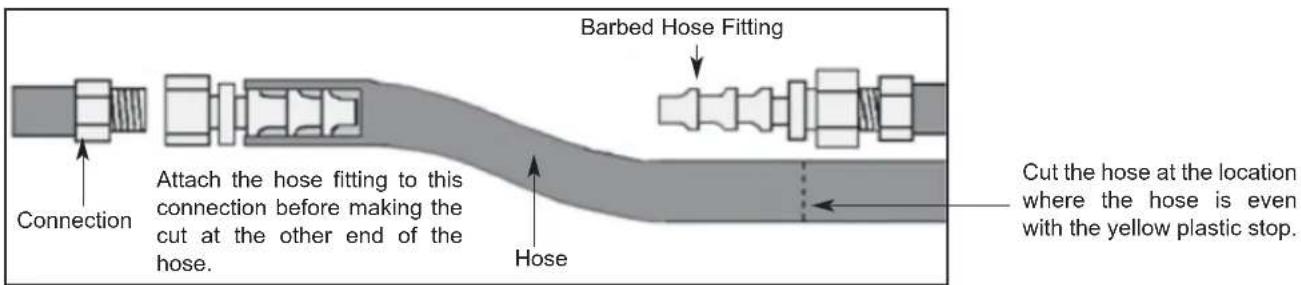
Due to the fact that each customer may have different requirements for the orientation of the gas booster heater relative to the main dishmachine, the hose lengths that connect the two units must be customized during each installation. The appropriate 3/4" hosing, fittings and gaskets have been provided.
To prevent incorrect measurements of the hose, it is recommended to place one barbed hose fitting into the end of the uncut length of hose coil and attach that fitting to an appropriate connection. Run the hose to the corresponding connection on the other unit before cutting the hose. Use a barbed hose fitting that is screwed into the second connection on the other unit before cutting the hose. Use a barbed hose fitting that is screwed onto the second connection to gauge the correct distance. Ensure a smooth "flow" of hose without any sharp turns or kinks.
To aid in pushing the barbed hose fitting into the hose, place the fitting on a hard surface (i.e. the floor) with the barbed end of the fitting pointing upward and push the hose down onto the fitting. A small amount of lubricant (i.e. petroleum jelly) may aid in this process.
SECTION 2: INSTALLATION/OPERATION INSTRUCTIONS
GAS CONVEYOR HOSE INSTALLATION (CONTINUED)
TYPICAL RECIRCULATING WATER HOOK-UP FOR ALL GAS HEATED CONVEYORS
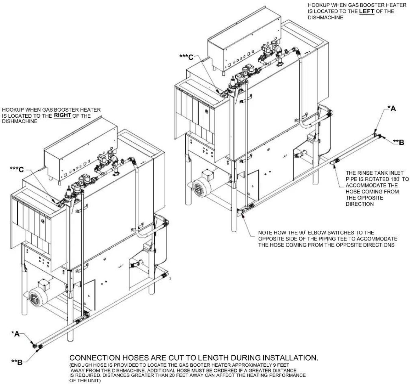
* HOSES MARKED A IN THE ABOVE ILLUSTRATIONS CONNECT TO THE INLET WATER CONNECTION OF THE GAS BOOSTER HEATER
** HOSES MARKED B IN THE ABOVE ILLUSTRATIONS CONNECT TO THE OUTLET WATER CONNECTION OF THE GAS BOOSTER HEATER
*** ITEMS MARKED C ARE THE INCOMING PLUMBING CONNECTIONS TO MACHINE THAT SHOULD BE 110 - 140 DEGREES
SECTION 2: INSTALLATION/OPERATION INSTRUCTIONS DISHMACHINE OPERATING INSTRUCTIONS
PREPARATION: Before proceeding with the start-up of the unit, verify the following:
- Close door(s) on dishmachine.
- Close the drain valve(s).
POWER UP (ELECTRICALLY-HEATED MODELS): To energize the unit, turn on the power at the service breaker. The voltage should have been previously verified as being correct. If not, the voltage will have to be verified.
POWER UP (STEAM-HEATED MODELS): To energize the unit, turn on the power at the service breaker. The voltage should have been previously verified as being correct. If not, the voltage will have to be verified. Ensure that the steam service is connected and that steam is flowing to the machine. Without steam, the water will not reach the required minimum temperatures that the machine is designed to operate at.
POWER UP (GAS-HEATED MODELS): To energize the unit, turn on the power at the service breaker. The voltage should have been previously verified as being correct. If not, the voltage will have to be verified. Ensure that the gas service is connected and that gas is flowing to the machine. Without gas, the water will not reach the required minimum temperatures that the machine is designed to operate at.
FILLING THE WASH TUB: Ensure that the delime switch is in the NORMAL position, and place the power switch into the ON position. The machine should fill automatically and shut off when the appropriate level is reached (just below the pan strainer). The wash tub must be completely filled before operating the wash pump to prevent damage to the component. Once the wash tub is filled, the unit is ready for operation.

Machines equipped with prewash sections should not be run without water in those sections. This can cause damage to components.
WARE PREPARATION: Proper preparation of ware will help ensure good results and less re-washes. If not done properly, ware may not come out clean and the efficiency of the dishmachine will be reduced. It is important to remember that a dishmachine is not a garbage disposal and that simply throwing unscraped dishes into the machine simply defeats the purpose altogether of washing the ware. Scraps should be removed from ware prior to being loaded into a rack. Pre-rinsing and pre-soaking are good ideas, especially for silverware and casserole dishes. Place cups and glasses upside down in racks so that they do not hold water during the cycle. The dishmachine is meant not only to clean, but to sanitize as well, to destroy all of the bacteria that could be harmful to human beings. In order to do this, ware must be properly prepared prior to being placed in the machine.
DAILY MACHINE PREPARATION: Refer to the section entitled "PREPARATION" at the top of this page and follow the instructions there. Afterwards, check that all of the chemical levels are correct and/or that there is plenty of detergent available for the expected workload.
WASHING A RACK OF WARE: To wash a rack, simply slide a rack of soiled ware into the load end of the machine. Once the machine is started, it should pull the rack through the machine and push it out the unload end. Once a rack has started through, you may put another rack in.
OPERATIONAL INSPECTION: Based upon usage, the pan strainers may become clogged with soil and debris as the work-day progresses. Operators should regularly inspect the pan strainers to ensure they have not become clogged. If the strainers do, they will reduce the washing capability of the machine. Instruct operators to clean out the pan strainers at regular intervals or as required by work load.
NOTE: On units equipped with prewash sections (AJ-86 and AJ-100), operators should also take the time to inspect the pre-wash section strainers and clean them as required by workload.
SHUTDOWN AND CLEANING (ELECTRICALLY-HEATED MODELS): At the end of the workday, place the power switch in the OFF position and open the door(s). Open the drain valves and allow the machine to drain completely. Remove the pawl bar assembly (clean as required). Remove the pan strainers and, if equipped, the prewash strainers, run off sheets and scrap basket strainer. Remove the wash and, if equipped, the prewash arms and verify that the nozzles and arms are free from obstructions. Flush the arms with fresh water. Remove the pump suction strainers and clean out as required. Remove the rinse tray assembly and clean. Remove the curtains and scrub with a mild detergent and warm water. Wipe out the inside of the unit and then reassemble with the components previously removed.
SECTION 2: INSTALLATION/OPERATION INSTRUCTIONS DISHMACHINE OPERATION INSTRUCTIONS (CONTINUED)
SHUTDOWN AND CLEANING (STEAM-HEATED MODELS): At the end of the workday, place the power switch in the OFF position, secure the flow of steam to the machine and open the door(s). Open the drain valves and allow the machine to drain completely. Remove the pawl bar assembly (clean as required). Remove the pan strainers and, if equipped, the prewash strainers, run off sheets and scrap basket strainer. Remove the wash and, if equipped, the prewash arms and verify that the nozzles and arms are free from obstructions. Flush the arms with fresh water. Remove the pump suction strainers and clean out as required. Remove the rinse tray assembly and clean. Remove the curtains and scrub with a mild detergent and warm water. Wipe out the inside of the unit and then reassemble with the components previously removed.
SHUTDOWN AND CLEANING (GAS-HEATED MODELS): At the end of the work day, shut down the gas booster in accordance with manufacturer's instructions. Place the power switch in the OFF position, secure the flow to the machine and open the door(s). Open the drain valves and allow the machine to drain completely. Remove the pawl bar assembly (clean as required). Remove the pan strainers and, if equipped, the prewash strainers, run off sheets and scrap basket strainer. Remove the wash and, if equipped, the prewash arms and verify that the nozzles and arms are free from obstructions. Flush the arms with fresh water. Remove the pump suction strainers and clean out as required. Remove the rinse tray assembly and clean. Remove the curtains and scrub with a mild detergent and warm water. Wipe out the inside of the unit and then reassemble with the components previously removed.
SECTION 2: INSTALLATION/OPERATION INSTRUCTIONS DETERGENT CONTROL
Detergent usage and water hardness are two factors that contribute greatly to how efficiently your dishmachine will operate. Using detergent in the proper amount can become, in time, a source of substantial savings. A qualified water treatment specialist can tell you what is needed for maximum efficiency from your detergent, but you should still know some basics so you'll understand what they are talking about.
First, you must understand that hard water greatly effects the performance of the dishmachine. Water hardness is the amount of dissolved calcium and magnesium in the water supply. The more dissolved solids in the water, the greater the water hardness. Hard water works against detergent, thereby causing the amount of detergent required for washing to increase. As you use more detergent, your costs for operating the dishmachine will increase and the results will decrease. The solids in hard water also may build-up as a scale on wash and rinse heaters, decreasing their ability to heat water. Water temperature is important in removing soil and sanitizing dishes. If the water cannot get hot enough, your results may not be satisfactory. This is why Jackson recommends that if you have installed the machine in an area with hard water, that you also install some type of water treatment equipment to help remove the dissolved solids from the water before it gets to the dishmachine.
Second, hard water may have you adding drying agents to your operating cycle to prevent spotting, when the real problem is deposited solids on your ware. As the water evaporates off of the ware, the solids will be left behind to form the spotting and no amount of drying agent will prevent this. Again, using treated water will undoubtedly reduce the occurrences of this problem.
Third, treated water may not be suitable for use in other areas of your operation. For instance, coffee made with soft water may have an acid or bitter flavor. It may only be feasible to install a small treatment unit for the water going into the dishmachine itself. Discuss this option with your qualified water treatment specialist.
Even after the water hardness problems have been solved, there still must be proper training of dishmachine operators in how much detergent is to be used per cycle. Talk with your water treatment specialist and detergent vendor and come up with a complete training program for operators. Using too much detergent has as detrimental effects as using too little. The proper amount of detergent must be used for job. It is important to remember that certain menu items may require extra detergent by their nature and personnel need to be made aware of this. Experience in using the dishmachine under a variety of conditions, along with good training in the operation of the machine, can go a long way in ensuring your dishmachine operates as efficiently as possible.
Certain dishmachine models require that chemicals be provided for proper operation and sanitization. Some models even require the installation of third-party chemical feeders to introduce those chemicals to the machine. Jackson does not recommend or endorse any brand name of chemicals or chemical dispensing equipment. Contact your local chemical distributor for questions concerning these subjects.
Some dishmachines come equipped with integral solid detergent dispensers. These dispensers are designed to accommodate detergents in a certain sized container. If you have such a unit, remember to explain this to your chemical distributor upon first contacting them.
As explained before, water temperature is an important factor in ensuring that your dishmachine functions properly. The data plate located on each unit details what the minimum temperatures must be for either the incoming water supply, the wash tank and the rinse tank, depending on what model of dishmachine you have installed. These temperatures may also be followed by temperatures that Jackson recommends to ensure the highest performance from you dishmachine. However, if the minimum requirements are not met, the chances are your dishes will not be clean or sanitized. Remember, a dish can look clean, but it may not be sanitized. Instruct your dishmachine operators to observe the required temperatures and to report when they fall below the minimum allowed. A loss of temperature can indicate a much larger problem such as a failed heater or it could also indicate that the hot water heater for your operation is not up to capacity and a larger one may need to be installed.
There are several factors to consider when installing your dishmachine to ensure that you get the best possible results from it and that it operates at peak efficiency for many years. Discuss your concerns with your local chemical distributor and water treatment specialist before there is a problem.
SECTION 2: INSTALLATION/OPERATION INSTRUCTIONS
STRIKER PLATE LIMIT SWITCH INSTALLATION INSTRUCTIONS
Installation Instructions:
- Wiring: The switch is wired common and normally open because of the hinge design. By interrupting the line in series with the door switches, the dishmachine ceases to operate. Refer to the machine schematic for details on how to wire the switch.
- Parts of the table switch are mounted in the dishtable, at the end of the table and under the table. See the drawing(s) for the relationship of the switch to the table.
- Move the limit switch as far down on the two slots as possible and see that the limit switch is straight on the base plate. This might require adjustment of the nut on the connector for the limit switch.
- Then adjust the inside and the outside connector nuts for the connector box so that it lines up even with the limit switch and the base plate.
- Tighten down the nuts for the seal so that they are tight.
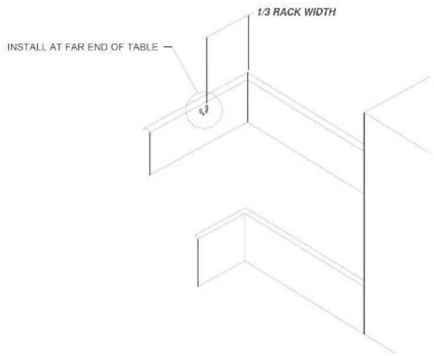
- If you have any difficulty you might have to adjust the connectors to the seal, screwing in or screwing out until the installation is straight on the table and the limit switch is actuated correctly by the rack.
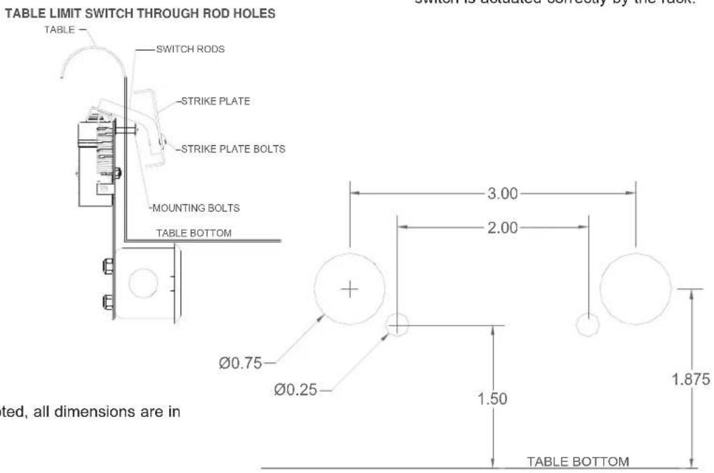
Unless noted, all dimensions are in inches.
SECTION 3: PREVENTATIVE MAINTENANCE
SECTION 3: PREVENTATIVE MAINTENANCE PREVENTATIVE MAINTENANCE
The dishmachines covered in this manual are designed to operate with a minimum of interaction with the operator. However, this does not mean that some items will not wear out in time. Jackson highly recommends that any maintenance and repairs not specifically discussed in this manual should be performed by QUALIFIED SERVICE PERSONNEL ONLY. Performing maintenance on your dishmachine may void your warranty if it is still in effect, so if you have a question or concern, do not hesitate to contact Jackson.
There are many things that operators can do to prevent catastrophic damage to the dishmachine. One of the major causes of component failure has to do with prescrapping procedures. A dishmachine is not a garbage disposal; any large pieces of material that are put into the machine shall remain in the machine until they are either broken up (after spreading out on your ware!) or physically removed. Strainers are installed to help catch debris, but they do no good of they are clogged. Have operators regularly inspect the pan strainers to ensure (1) that they are free of soil and debris and (2) they are laying flat in the tub.
When cleaning out strainers, do NOT beat them on waste cans. The strainers are made of metal and can be forgiving; but once severe damage is done, it is next to impossible for the strainer to work in the way it was designed to. Wipe out strainers with a rag and rinse under a faucet if necessary. For stubborn debris, a toothpick should be able to dislodge any obstructions from the perforations. Always ensure that strainers are placed back in the machine before operation and that they lay flat in the tub.
You may wish to also refer to the page entitled “Detergent Control” in order to learn more about how your water hardness will effect the performance of your machine. Hard water makes dishmachines work harder and decreases efficiency.
Again, it is important to remind operators that trying to perform corrective maintenance on the dishmachine could lead to larger problems or even cause harm to the operator. If a problem is discovered; secure the dishmachine using proper shut down procedures as listed in this manual and contact Jackson.
Some problems, however, may having nothing to do with the machine itself and no amount of preventative maintenance is going to help. A common problem has to do with temperatures being too low. Verify that the water temperatures coming to your dishmachine match the requirements listed on the machine data plate. There can be a variety of reasons why your water temperature could be too low and you should discuss it with Jackson to determine what can be done.
By following the operating and cleaning instructions in this manual, you should get the most efficient results from your machine. As a reminder, here are some steps to take to ensure that you are using the dishmachine the way it was designed to work:
- Ensure that the water temperatures match those listed on the machine data plate.
- Ensure that all strainers are in place before operating the machine.
- Ensure that all wash and/or rinse arms are secure in the machine before operating.
- Ensure that drains are closed/sealed before operating.
- Remove as much soil from dishes by hand as possible before loading into racks.
- Do not overfill racks.
- Ensure that glasses are placed upside down in the rack.
- Ensure that all chemicals being injected to machine have been verified as being at the correct concentrations.
- Clean out the machine at the end of every workday as per the instructions in the manual.
- Always contact Jackson whenever a serious problem arises.
- Follow all safety procedures, whether listed in this manual or put forth by local, state or national codes/regulations.
SECTION 3: PREVENTATIVE MAINTENANCE D226 MAINTENANCE
WARNING: Maintenance should only be performed by authorized service personnel in order to ensure safe and effective workmanship, while minimizing danger to operating personnel. The D226 Steam Booster is designed to operate at temperatures capable of causing burns to personnel. Always allow the unit to cool down to an acceptable temperature prior to performing any maintenance.
Very little maintenance is required to be performed on the D226 Booster. So long as the steam and water used with the unit have the proper filtration and are operated at the correct temperature and pressures, then you should expect many years of reliable service out of your system.
MAINTENANCE OF THE WATER PRESSURE REGULATOR:
Incoming water pressure can be regulated by adjusting the water pressure regulator on the system. In order to adjust pressure, loosen the top nut on the regulator. This will allow you to turn the adjusting screw. Turn the adjusting screw clockwise to increase pressure and counter-clockwise to decrease. Pressure can be read on the pressure gauge located on the water outlet side of the heat exchanger. Once the desired pressure is achieved, tighten the top nut to ensure that the adjustment cannot be accidentally changed.
The water pressure regulator has an internal strainer that can be removed through the bottom hexagonal plug. This may need to be periodically checked depending on the water quality. It is important that the water supply to the water pressure regulator be secured prior to trying to clean the strainer.
MAINTENANCE OF THE RELIEF VALVES, SAFETY VALVES AND THERMOSTAT:
These components are shipped from the factory preset and should not be tampered with. None of these components are considered adjustable and no attempt should be made to do so. If a component does not appear to be working properly, then it should be replaced immediately by an authorized service representative.
SECTION 3: PREVENTATIVE MAINTENANCE
LUBRICATION CHART FOR DRIVE GEAR
Note: The maintenance procedures detailed here are manufacturer's instructions for the WINSMITH brand of gear reducer that is installed on the rack conveyors covered in this manual.
Ambient Temperature -30 - 15°F 16 - 50°F 51 - 95°F 51 - 95°F 96 - 131°F 96 - 131°F
Final Stage Worm Speed ^1 up to 2000 FPM up to 2000 FPM up to 450 FPM above 450 FPM up to 450 FPM above 450 FPM
ISO Viscosity Grade 220 460 680 460 680 460
AGMA Lubricant No. 5S #7 Compounded #8 Compounded #7 Compounded 8S 7S
| Mobil | SHC 630 | 600W Super Cylinder | Extra Hecla Super | 600W Super Cylinder | SHC 636 | SHC 634 |
| American Lubricants | SHC-90W | AGMA #7 Gear Oil | AGMA #8 Gear Oil | AGMA #7 Gear Oil | N/A | N/A |
| Castrol | Tribol 800/220 | Tribol 1105-7C | Tribol 1105-8C | Tribol 1105-7C | Tribol 800/680 | Tribol 800/460 |
| Chevron | Tegra 220 | Cylinder Oil W460 | Cylinder Oil W680 | Cylinder Oil W460 | Tegra 680 | Tegra 460 |
| Conoco | Syncon R & O 220 | Inca Oil 460 | Inca Oil 680 | Inca Oil 460 | N/A | Syncon R & O 460 |
| Exxon (Esso) | Teresstic SHP220 | Spartan EP 460 | Spartan EP 680 | Spartan EP 460 | Teresstic SHP 680 | Teresstic SHP 460 |
| Fiske Brothers | SPO-MG | SPO-277 | SPO-288 | SPO-277 | N/A | N/A |
| Shell | Omala RL 220 | Valvata J 460 | Valvata J 680 | Valvata J 460 | Omala RL 680 | Omala RL 460 |
| Texaco | Pinnacle 220 | Vanguard 460 | Vanguard 680 | Vanguard 460 | Pinnacle 680 | Pinnacle 460 |
(1) The sliding velocity in feet per minute (FPM) for standard ratios is determined by multiplying the speed of the worm in RPM by the factor from the table below. For selecting proper lubricant, use the speed of the worm in the final stage (input RPM divided by the first stage ratio).
SECTION 3: PREVENTATIVE MAINTENANCE DRIVE MOTOR GEAR REDUCER PREVENTATIVE MAINTENANCE
Note: The maintenance procedures detailed here are manufacturer's instructions for the WINSMITH brand of gear reducer that is installed on the rack conveyors covered in this manual.
Lubrication & Maintenance:
Factory filling - WINSMITH speed reducers are oil filled at the factory to the proper level for the standard mounting position that you will find it in on the unit. The oil level should be checked and adjusted (if necessary) prior to operation, using the oil level plug provided and while the unit is oriented in its operating position.
Ambient temperature - If the operating ambient temperature is other than 51 - 95°F, then refer to the lubrication chart and refill the unit with the correct grade based on actual ambient temperature and operating speed. See “Oil changing” below for additional information.
Oil changing - When changing the oil for any reason, it should be remembered that oils of various types may not be compatible. Therefore, when changing to a different oil, it is recommended that the housing be completely drained and thoroughly flushed with a light flushing oil prior to refilling with the appropriate lubricant. The oil level should be rechecked after a short period of operation and adjusted, if necessary. When changing double reduction models, each housing should be drained and filled independently, even though there may be a common level.
Initial oil change: The new oil in a speed reducer should be changed at the end of 250 hours of operation. This is equivalent to 30 days of peration for 8 hours per day; 15 days of operation for 16 hours per day, or 10 days of operation for 24 hours per day.
Subsequent oil changes: Under normal conditions, after the initial oil change, the oil should be changed after every 2500 hours of operation, or every 6 months, whichever occurs first. Under severe conditions (rapid temperature changes, moist, dirty or corrosive environment) it may be necessary to mchange oil at intervals of one to three months. Periodic examination of oil samples taken from the unit will help establish the appropriate interval.
Synthetic oils: Synthetic lubricants can be advantageous over mineral oils in that they generally are more stable, have a much longer life, and operate over a wider temperature range. These oils are appropriate for any application but are especially useful when units are subjected to low start-up temperatures or high operating temperatures. However, continuous operation above 225^ F may cause damage to seals or other components. It is recommended that the initial oil be changed or filtered after the first 1500 hours of operation to remove metal particles that accumulate during break-in. Subsequent oil changes should be made after 5000 hours operation if units are operating in a clean environment. This can be extended to 10,000 hours if using new reformulated Mobil SHC lubricants (orange in color) and the lubricant remains free of contamination over this period. See comments under “Subsequent oil changes” for discussion of severe ambient conditions.
Long term storage or infrequent operation: If a speed reducer is to stand idle for an extended period of time, either prior to installation or during use, it is recommended that the unit be filled completely with oil to protect interior parts from rust and corrosion due to internal condensation. Be sure to drain the oil to the proper level before placing the speed reducer in service.
Grease fittings: Some units are equipped with grease fittings to lubricate bearings not adequately lubricated by the oil splash. These fittings must be lubricated every 3 - 6 months depending on operating conditions. bearing greases must be compatible with the type of gear lubricant being used (i.e. mineral, synthetic, food grade, etc.). For mineral oils, use a high quality lithium base NLGOI #2 bearing grease. For synthetic oils, use a synthetic bearing grease such as Mobil Synthetic Universal grease, Mobilith SHC 100 or a suitable equivalent. For food grade lubricants, use Chevron FM grease, NGLI 2, or equivalent.
Low Input speeds (under 1600 RPM): When input speeds are less than 1600 RPM, grease fittings will be required to lubricate any bearings not partially covered by the normal oil level.
Oil temperature: Speed reducers in normal operation can generate temperatures up to 200^ F depending on the type of reducer and the severity of the application 9 loading, duration of service, ambient temperatures). Excessive oil temperatures may be the result of several factors including overloading, overfilling, underfilling or inadequate cooling.
Nominal Ratio
Size 5 7.5 10 15 20 25 30 40 50 60 80 100
Lubricant selections are provided by the lubricant manufacturer based on AGMA recommended viscosity grades. Viscosity grades are based on Lubrication Standard ANSI/AGMA 9005-D94.
SECTION 4: TROUBLESHOOTING SECTION
SECTION 4: TROUBLESHOOTING COMMON PROBLEMS

WARNING: Inspection, testing and repair of electrical equipment should be performed only by qualified service personnel. Certain procedures in this section require electrical tests or measurements while power is applied to the machine. Exercise extreme caution at all times. If test points are not easily accessible, disconnect power, attach
test equipment and reapply power to test. When replacing electrical parts, disconnect power at source circuit breaker.
Problem: Nothing on dishmachine operates. The power switch is ON and the power indicator light is OFF.
- Machine is not wired correctly to incoming power source. Have an electrician verify wiring.
- Machine circuit breaker is tripped. Reset the circuit breaker. If it trips again, contact an electrician to verify the machine amp draw.
- Service breaker is tripped. Reset the service breaker. If it trips again, contact an electrician to verify the machine amp draw.
Problem: Machine will not fill. The power switch is ON and the power indicator light is ON.
- No water supply to machine. Verify that water lines have been connected to the machine.
- Dishmachine doors are not closed. Close doors completely.
- Incoming water solenoid valve damaged/faulty. Verify that the valve is operating. If not, replace.
- Tank floats faulty. Verify the wiring of the floats. Verify that no debris is jamming the floats. Replace if necessary.
Problem: Machine fills, but fill is weak.
- Low incoming water pressure. Verify that incoming water pressure during fill is 20 ± 5 PSI.
- Incoming water solenoid is clogged. Verify that debris is not entrapped in valve. If so, remove debris.
Problem: Low wash tank temperature.
- Low incoming water temperature. Verify that the incoming water temperature matches what is indicated on the machine data plate.
- Heater not energizing. Verify that the wash tank heater is operating. If not, replace.
- Low incoming voltage. Have an electrician verify that the power coming to the machine is the same as indicated on the data plate.
Problem: Low wash arm pressure, poor spray pattern.
- Clogged wash arm nozzles. Verify that nozzles are not clogged with debris. If so, remove debris.
- Clogged wash tank or wash pump strainers. Clean out strainers if necessary.
- Worn wash pump impeller. Verify status of impeller, replace if necessary.
Problem: Low prewash arm pressure, poor spray pattern.
- Clogged prewash arm nozzles. Verify that nozzles are not clogged with debris. If so, remove debris.
- Clogged prewash tank or prewash pump strainers. Clean out strainers if necessary.
- Worn prewash pump impeller. Verify status of impeller, replace if necessary.
Problem: Inadequate rinse.
- Low incoming water pressure. Verify that incoming water pressure during fill is 20 ±5 PSI.
- Incoming water solenoid is clogged. Verify that debris is not entrapped in valve. If so, remove debris.
Problem: Pawl bar moves with no load, but does not move when loaded.
- Clutch on drive assembly is out of adjustment. Adjust as required.
SECTION 4: TROUBLESHOOTING COMMON PROBLEMS
Problem: Pawl bar does not move.
- Failed or broken overload spring. Replace spring if necessary.
- No power to the drive motor/failed drive motor. Verify power and wiring connections to the motor. If necessary, replace the motor.
- Pawl bar not properly installed. Verify that the pawl bar is installed correctly.
Problem: Racks go through the machine, but results are poor.
- Verify that detergent is being dispensed into the machine at the appropriate quantities for the water volume. If not, get detergent to appropriate level and review results of washing ware.
- Clogged strainers/scrap basket. Clean out strainers and scrap basket and replace.
- Ware not being properly prescrapped. Review paragraph entitled "Ware Preparation" in Operating Instructions.
- Wash or rinse arms missing end plugs or caps. Verify and replace as required.
- Low tank heat.
- Inadequate rinse.
- Incorrect voltage coming to the machine. Verify that the voltage matches that on the machine data plate.
- Wash pump cavitation due to low water level. Verify that the drains are shut and that the water level is correct.
Problem: Spotting of silverware, glasses and dishes.
- Incorrect final rinse temperature. Verify that the rinse water temperature matches that which is listed on the machine data plate.
- Clogged wash and/or rinse nozzles and arms. Remove the arms and verify that they and their nozzles are from debris.
- Excessively hard water. Install a water softener to reduce hardness.
- Loss of water pressure due to clogged/obstructed wash pump. Turn the power off to the machine at the source. Drain the wash tank of water and verify that the pump intake is free from debris.
- Improper scrapping procedures. Review the paragraph entitled "Ware Preparation" in Operating Instructions.
- incorrect detergent/chemical concentrations. Verify that the detergent/chemical concentrations are correct for the associated water volume.
TORQUE SETTINGS
When replacing components either in the control box or the heater box area, the manufacturer has suggestions on how much to torque the screws and nuts used in securing items to the machine. Refer to the table below for the torque specifications:
ITEMS
TORQUE SPEC
Relays 16 In/lbs
Heater Contactor 35 In/lbs
Heater Nuts 16 In/lbs
Terminal Block 50 In/lbs
SECTION 4: TROUBLESHOOTING
D226 TROUBLESHOOTING SECTION

WARNING: Inspection, testing and repair of electrical equipment should be performed only by qualified service personnel. Certain procedures in this section require electrical tests or measurements while power is applied to the machine. Exercise extreme caution at all times. If test points are not easily accessible, disconnect power, attach
test equipment and reapply power to test. When replacing electrical parts, disconnect power at source circuit breaker.
Problem: Power light does not illuminate.
- Power not connected to the unit through the control box. Open the control box cover and verify that incoming power lines are connected and light.
- Service breaker tripped or open. Verify that the breaker is closed.
- Power switch connections could be loose. Ensure that the connections are of sound quality.
- Power switch is faulty. Replace the power switch.
- Power light is faulty. Replace the light.
Problem: Water pressure is too low.
- Water pressure regulator is out of adjustment. Follow the instructions provided in the maintenance section and adjust so that the flow pressure is 20 ± 5 PSI.
- Water pressure regulator internal strainer is clogged. Clean in accordance with the instructions provided in the maintenance section.
- Water pressure regulator is faulty. Replace the regulator.
- Water pressure gauge is faulty or the cut off from the system. Verify that the test cock valve under the gauge is open to allow for the sensing of line pressure. Replace gauge if necessary.
- Heat exchanger is clogged. Replace the heat exchanger.
Problem: Solenoid valve is not opening/shutting.
- Power not connected to the unit through the control box. Open the control box cover and verify that incoming power lines are connected and light.
- Service breaker tripped or open. Verify that the breaker is closed.
- Power switch connections could be loose. Ensure that the connections are of sound quality.
- Power switch is faulty. Replace the power switch.
- Thermostat is faulty. Replace the thermostat.
- Solenoid wires are loose or broken. Verify that the electrical connections are of sound quality.
- Faulty solenoid coil. Replace the solenoid.
Problem: Outlet water temperature too low.
- Power not connected to the unit through the control box. Open the control box cover and verify that incoming power lines are connected and light.
- Service breaker tripped or open. Verify that the breaker is closed.
- Power switch connections could be loose. Ensure that the connections are of sound quality.
- Power switch is faulty. Replace the power switch.
- Thermostat is faulty. Replace the thermostat.
- Solenoid wires are loose or broken. Verify that the electrical connections are of sound quality.
- Faulty solenoid coil. Replace the solenoid.
- Steam flow pressure is too low for the unit. Verify that the steam flow is 15-25 PSIG.
- Water flow pressure is too high. Follow the instructions provided in the maintenance section and adjust so that the flow pressure is 20 ± 5 PSI.
- Heat exchanger is clogged. Replace the heat exchanger.
- Insufficient volume of steam to unit. Check the line size and flow pressure.
SECTION 5: PARTS SECTION
SECTION 5: PARTS SECTION
AJ-64 CONTROL BOX ASSEMBLY
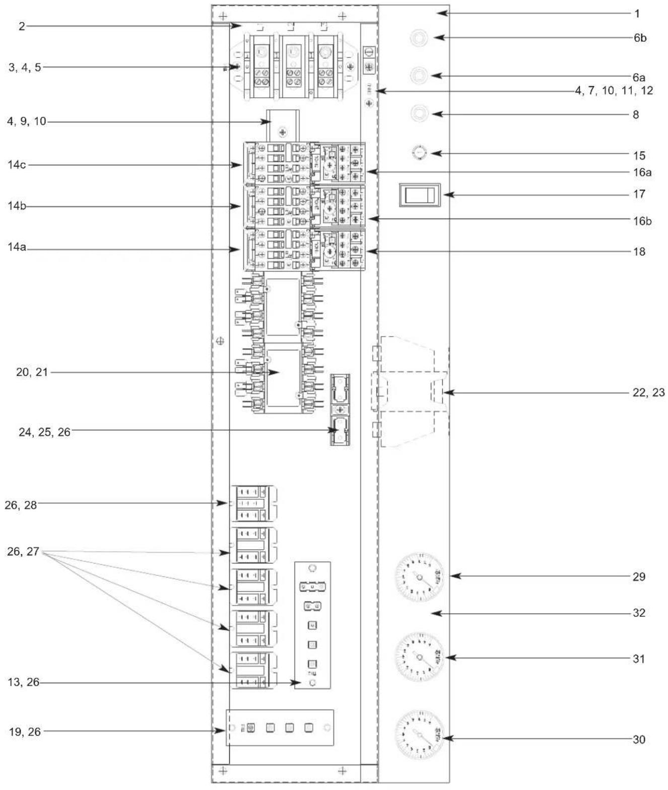
SECTION 5: PARTS SECTION
AJ-64 CONTROL BOX ASSEMBLY (CONTINUED)
ITEM QTY DESCRIPTION Mfg. No.
1 1 Electrical Box Weldment 05700-041-88-50
2 1 Decal, L1-L2-L3 09905-101-12-66
3 1 Terminal Block 05940-011-48-27
4 6 Lockwasher, #10 05311-273-02-00
5 2 Screw, 10-32 x 3/4" Long Phillips Trusshead 05305-011-62-17
6a 1 Light, Amber (Wash Heater Overload) (Not used on steam or gas models) 05945-111-44-44
6b 1 Light, Amber (Rinse Heater Overload) (Not used on steam or gas models) 05945-111-44-44
7 1 Wire Lug, 2 AWG to 14 AWG 05940-200-76-00
8 1 Light, Red (Power) 05945-111-44-45
9 1 Din Rail
10 3 Screw, 10-32 x 1/2" Long Phillips Trusshead 05305-011-39-36
11 1 Washer, Flat, 1/4"
12 1 Decal, Ground
13 1 Terminal Board
14a 1 Drive Motor Contactor
14b 1 Wash Pump Motor Contactor 05945-111-68-38
14c 1 Recirculating Rinse Pump Motor Contactor
15 1 Circuit Breaker (208 & 230 volt models only)
16a 1 Recirculating Rinse Pump Motor Overload (See motor overloads chart)
16b 1 Wash Pump Motor Overload (See motor overloads chart)
17 1 Switch, ON/FILL & OFF/DRAIN
18 1 Drive Motor Overload (See motor overloads chart)
19 1 Terminal Board
20 2 Heater Contactor (Not available on steam or gas models)
21 2 Screw, 10-32 x 3/8" Long Phillips Trusshead 05305-173-12-00
22 1 Transformer
23 4 Locknut, 10-24 with Nylon Insert
24 1 Fuse Holder (460 volt models only)
25 1 Fuse (460 volt models only)
26 12 Screw, 6-32 x 3/8" Long Phillipshead
27 4 Control Relay, 2 Pole
28 1 Relay, 3 Pole
29 1 Rinse Thermometer
Decal, Rinse 180°F
30 1 Wash Thermometer
Decal, Wash 150°F
31 1 Power Rinse Thermometer
Decal, Power Rinse 160°F
32 1 Decal, Gauge
05700-021-72-75
05311-174-01-00
09905-011-86-86
05940-002-78-97
05945-111-68-38
05945-111-68-38
05925-011-68-34
N/A
N/A
05930-011-49-55
N/A
05940-021-89-41
05945-002-24-70
05950-011-68-35
05310-373-01-00
05920-011-72-89
05920-011-72-88
05305-171-02-00
05945-111-35-19
05945-111-72-51
06685-111-68-49
09905-002-97-62
06685-111-87-13
09905-002-97-61
06685-111-87-13
09905-003-01-31
09905-021-82-65
Items not shown:
| Grommet, 1/2" OD x 3/8" ID | 05325-011-46-73 |
| Bushing, Heyco SB100 | 05975-210-09-00 |
| Plug, Heyco 2700 G-875 | 05975-011-47-81 |
| Control Box Cover | 05700-031-66-88 |
| Control Box Cover Hinge Weldment | 05700-021-68-57 |
| Control Hinge Rod | 05700-011-68-58 |
| MANUAL/DELIME Switch (Located on rear of control box) | 05930-301-22-18 |
| MANUAL/DELIME Decal | 09905-011-74-61 |
| Copper Conductors Only Decal | 09905-011-47-35 |
| Control Box Leg | 05700-011-71-47 |
SECTION 5: PARTS SECTION
AJ-86 & AJ-100 CONTROL BOX ASSEMBLY
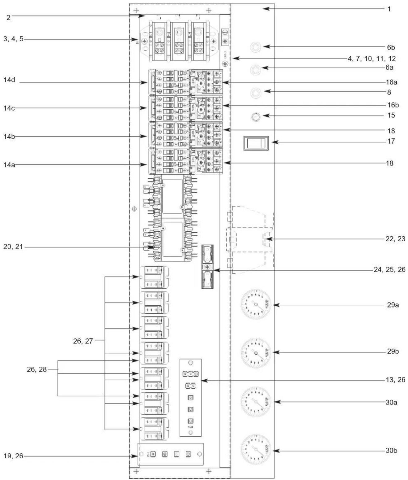
SECTION 5: PARTS SECTION
AJ-86 & AJ-100 CONTROL BOX ASSEMBLY (CONTINUED)
ITEM QTY DESCRIPTION Mfg. No.
1 1 Electrical Box Weldment 05700-041-88-50
2 1 Decal, L1-L2-L3 09905-101-12-66
3 1 Terminal Block 05940-011-48-27
4 6 Lockwasher, #10 05311-273-02-00
5 2 Screw, 10-32 x 3/4" Long Phillips Trusshead 05305-011-62-17
6a 1 Light, Amber (Wash Heater Overload) (Not used on steam or gas models) 05945-111-44-44
6b 1 Light, Amber (Rinse Heater Overload) (Not used on steam or gas models) 05945-111-44-44
7 1 Wire Lug, 2 AWG to 14 AWG 05940-200-76-00
8 1 Light, Red (Power) 05945-111-44-45
9 1 Din Rail 05700-021-94-96
10 3 Screw, 10-32 x 1/2" Long Phillips Trusshead 05305-011-39-36
11 1 Washer, Flat, 1/4" 05311-174-01-00
12 1 Decal, Ground 09905-011-86-86
13 1 Terminal Board 05940-002-78-97 14a 1 Drive Motor Contactor 05945-111-68-38
14b 1 Wash Pump Motor Contactor 05945-111-68-38
14c 1 Recirculating Rinse Pump Motor Contactor 05945-111-68-38
14d 1 Prewash Pump Motor Contactor 05945-111-68-38
15 1 Circuit Breaker (208 & 230 volt models only)
16a 1 Recirculating Rinse Pump Motor Overload (See motor overloads chart)
16b 1 Wash Pump Motor Overload (See motor overloads chart)
17 1 Switch, ON/FILL & OFF/DRAIN 05930-011-49-55
18 1 Drive Motor Overload (See motor overloads chart) N/A
19 1 Terminal Board 05940-021-89-41 20 2 Heater Contactor (Not available on seam models) 05945-002-24-70
21 2 Screw, 10-32 x 3/8" Long Phillips Trusshead 05305-173-12-00
22 1 Transformer 05950-011-68-35
23 4 Locknut, 10-24 with Nylon Insert 05310-373-01-00
24 1 Fuse Holder (460 volt models only) 05920-011-72-89
25 1 Fuse (460 volt models only) 05920-011-72-88 26 12 Screw, 6-32 x 3/8" Long Phillipshead 05305-171-02-00
27 7 Control Relay, 2 Pole (5 for Gas models, 1 not shown) 05945-111-35-19
28 3 Relay, 3 Pole (Gas models only) 05945-111-72-51
29a 1 Rinse Thermometer, 96" (L-R & R-L models) 06685-111-68-49 Decal, Rinse 180°F 09905-002-97-62
29b 1 Power Rinse Thermometer, 96" (L-R models) 06685-111-68-49 29b 1 Power Rinse Thermometer, 120" (R-L models) 06685-111-87-13 Decal, Power Rinse 160°F 09905-003-01-31
30a 1 Wash Thermometer, 120" (L-R models) 06685-111-87-13 30a 1 Wash Thermometer, 96" (R-L models) 06685-111-68-49 Decal, Wash 150°F 09905-002-97-61
30b 1 Prewash Thermometer, 120" (L-R & R-L models) 06685-111-87-13
31 1 Power Rinse Thermometer 06685-111-87-13 Decal, Power Rinse 160°F 09905-003-01-31 32 1 Decal, Gauge 09905-021-82-65
Items not shown:
| Grommet, 1/2” OD x 3/8” ID | 05325-011-46-73 |
| Bushing, Heyco SB100 | 05975-210-09-00 |
| Plug, Heyco 2700 G-875 | 05975-011-47-81 |
| Control Box Cover | 05700-031-66-88 |
| Control Box Cover Hinge Weldment | 05700-021-68-57 |
| Control Hinge Rod | 05700-011-68-58 |
| MANUAL/DELIME Switch (Located on rear of control box) | 05930-301-22-18 |
| MANUAL/DELIME Decal | 09905-011-74-61 |
| Copper Conductors Only Decal | 09905-011-47-35 |
| Control Box Leg | 05700-011-71-47 |
SECTION 5: PARTS SECTION MOTOR OVERLOADS
AJ-64 SERIES MOTOR OVERLOAD CHART:
208-230V/60 HZ/1 PHASE 208-230V/60 HZ/3 PHASE 460V/60 HZ/3 PHASE
Drive Motor Not Applicable 05945-111-68-39 05945-111-69-12
PreWash Motor Not Applicable Not Applicable Not Applicable
Wash Motor Not Applicable 05945-111-68-40 05945-111-68-41
Power Rinse Motor Not Applicable 05945-111-68-40 05945-111-68-41
AJ-86 SERIES MOTOR OVERLOAD CHART:
208-230V/60 HZ/1 PHASE 208-230V/60 HZ/3 PHASE 460V/60 HZ/3 PHASE
Drive Motor Not Applicable 05945-111-68-39 05945-111-69-12
PreWash Motor Not Applicable 05945-111-68-41 05945-111-69-13
Wash Motor Not Applicable 05945-111-68-40 05945-111-68-41
Power Rinse Motor Not Applicable 05945-111-68-40 05945-111-68-41
AJ-100 SERIES MOTOR OVERLOAD CHART:
208-230V/60 HZ/1 PHASE 208-230V/60 HZ/3 PHASE 460V/60 HZ/3 PHASE
Drive Motor Not Applicable 05945-111-68-39 05945-111-69-12
PreWash Motor Not Applicable 05945-111-68-40 05945-111-68-41
Wash Motor Not Applicable 05945-111-68-40 05945-111-68-41
Power Rinse Motor Not Applicable 05945-111-68-40 05945-111-68-41
SECTION 5: PARTS SECTION HEATER BOX ASSEMBLY
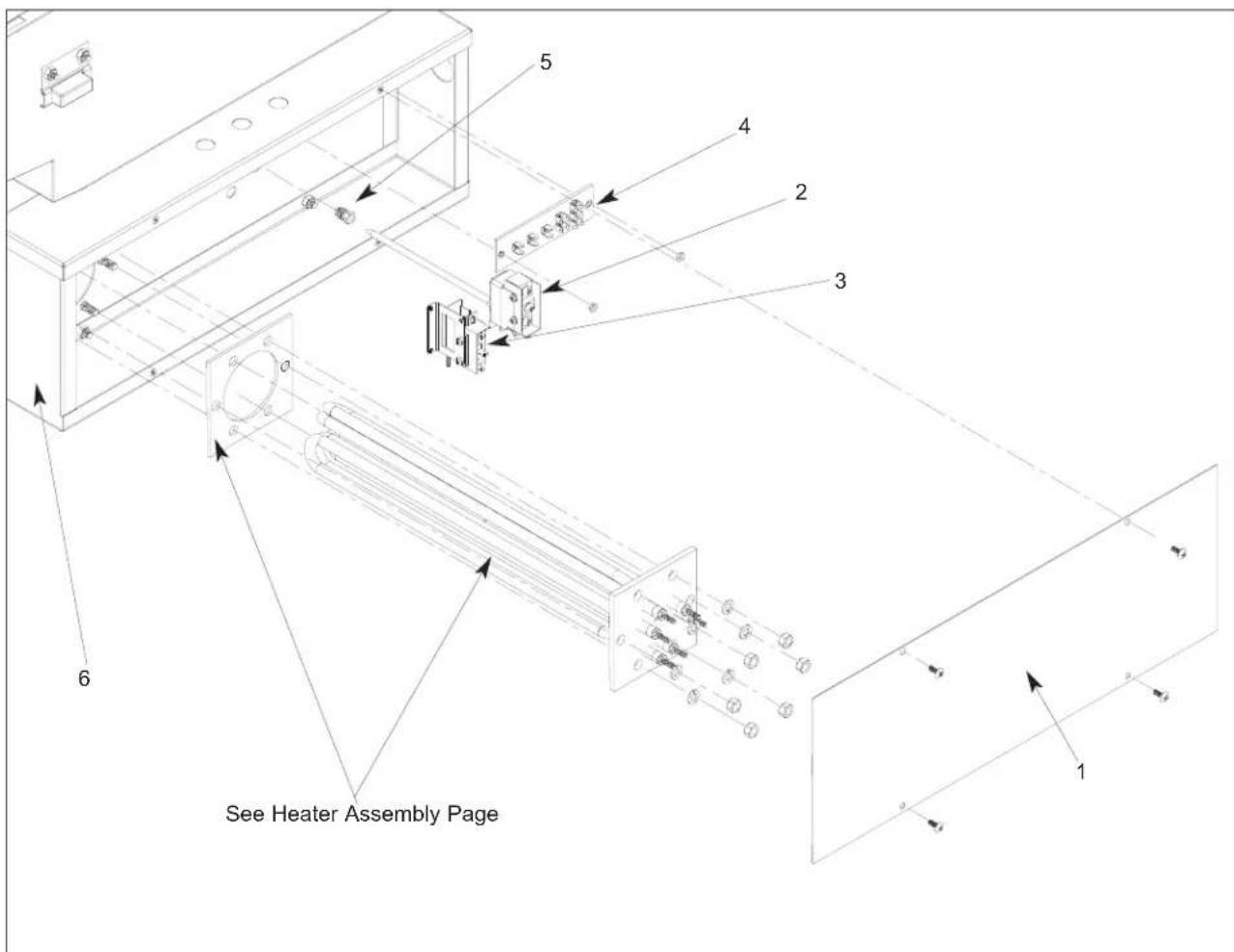
ITEM QTY DESCRIPTION Mfg. No.
1 1 Heater Box Cover 05700-031-81-61
2 1 Kit, Thermostat, Wash Regulating (Electrically Heated) 06401-003-18-20
2 1 Kit, Thermostat, Wash Regulating (Steam Heated) 06401-003-18-21
3 1 Thermostat, High Limit 05930-011-49-43
4 1 Terminal Board 05940-002-78-97
5 1 Fitting, 1/4", Imperial Brass 05310-924-02-05
6 1 Heater Box Weldment 05700-002-41-18
SECTION 5: PARTS SECTION
HEATER ASSEMBLY
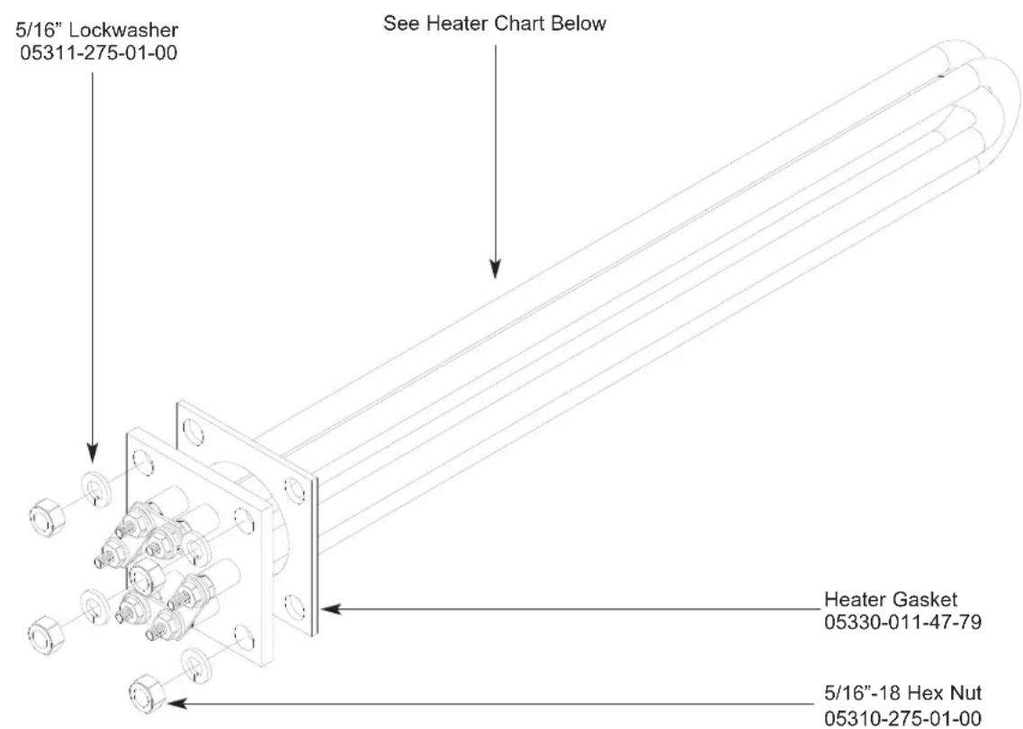
Heater Chart
| Model | Volts | Phase | KW | Part Number |
| All* 208 1 10 06401-003-12-94 | ||||
| 230 1 | 10 06401-003-12-95 | |||
| 208 3 | 10 06401-003-12-94 | |||
| 230 3 | 10 06401-003-12-95 | |||
| 460 3 | 10 06401-003-12-96 | |||
Heater Chart
Model KW 208V Models 230V Models 460V Models
All* 15 04540-121-68-45 04540-121-68-46 04540-121-68-47
* - "CS" & "CGP" models do not use electric heaters in the wash tank or power rinse tank.
SERVICE NOTE: When replacing the tub heaters, it is HIGHLY recommended that you also change out the gasket as well. Once installed, gaskets become compressed and are subjected to extreme temperature changes. Replacing the gasket with a new one when replacing the heater may prevent future leaks.
SERVICE NOTE: The nuts used to secure the heater to the tub should be torqued to 16 in-lbs. After tightening, the unit should be allowed to heat up and operate normally for approximately 30 minutes. Secure power to the machine and check the nuts once more to ensure that they are torqued to 16 in-lbs.
SECTION 5: PARTS SECTION HEATER ASSEMBLY (CONTINUED)
The wash tank heater system is electrically connected in the circuit so that they are dependent upon the dishwasher being properly filled with and maintaining a safe water level, two thermostats (mounted in the heater box behind the dress panel), float switch (mounted in the wash tank), and the heater relay (mounted in control box) with the heater being activated by the thermostats.
Once the dishwasher has been filled to the correct level, the heater should operate automatically. Should the tank heat be too high, too low or no indication of temperatures at all, the following checkout should be made.
Note: The following checkout should be made by either a qualified service person or electrician.
A- Checkout of the heater system
1- If the temperature is too high, adjust thermostat using instructions on the page entitled "Thermostats".
2- If temperature is too low, adjust thermostat as above, then:
a - Turn off power to machine by placing customer's circuit breaker in the "OFF" position. Turn off machine circuit breaker located on right side of control box.
b - Remove cover from control box on top of dishwasher.
c - Make sure water temperature is below 140°F.(preferably about 130°F.).
d - Turn on both circuit breakers. Observe heater relay (R1) while the power switch is turned "ON" and "OFF". If relay contacts move in and out, the heater relay is operating correctly: if not proceed to "C".
B- If heater relay (R1) closes:
1 - Check power supply at incoming terminal board L1, L2 & L3. It should be the same voltage as indicated on the machine data plate.
2 - Check power at connections on heater relay (R1). The voltage should agree with the voltage on the machine data plate. If not, check wires for breaks or bad connections.
3 - Check power at terminals of heater which should agree with the data plate. If not check wires for breaks or bad connections.
4 - Temperatures should rise as explained in "C-1", and amperage may be checked according to those instructions. Replace any defective elements.
C - If heater relay (R1) does not close.
1 - There is an insulated movable insulated movable bar on relay across the top. With an insulated probe, depress this bar and observe the thermometer: the temperature should rise noticeably in a minute or two. If it moves slowly, it would indicate that the element is faulty. If it moves constantly higher at a good rate, elements should be good.
Note: A check with an amp probe at heater relay (R1) terminals should be made to verify the amp draw on each leg. This should be appropriate for the voltage and phase indicated on the data plate
HEATER PROTECTION & AUTOMATIC FILL
This control is activated when the power switch is turned "ON". The primary function is to automatically energize the wash tank heat circuit. It will also cutoff the wash tank heat circuit should the water be accidentally drained from the machine with the power switch still "ON". The power switch should always be turned-off before draining the unit.
This water level control consists of two (2) floats that operate when the power switch is turned on and works in conjunction with the thermostats and heater relays.
When the power switch is turned "ON" water starts to enter the dishmachine. When it reaches the proper level the normally open contacts in the water level float switch close activating the heating circuit for tank heat.
If the water level below the correct level while power is still on, the float switch will sense the lack of water and de-activate the heater.
SECTION 5: PARTS SECTION
FRAME WELDMENTS/DRESS PANELS
FRAME WELDMENTS
Model Left to Right Part Number Right to Left Part Number
AJ-64's 05700-002-73-00 05700-002-73-00
AJ-86's 05700-041-83-65 05700-041-83-65
AJ-86CGP 05700-041-83-65 05700-041-83-65
AJ-100's 05700-041-91-00 05700-041-91-00
AJ-100CGP 05700-041-91-00 05700-041-91-00
Bullet Feet (4 per model) - order using part number 05340-011-71-74.
FRONT DRESS PANELS
Model Left to Right Part Number Right to Left Part Number
AJ-64's 05700-002-40-41 05700-002-40-41
AJ-86's 05700-031-83-68 05700-041-86-60
AJ-86CGP 05700-002-89-68 05700-041-86-60
AJ-100's 05700-041-94-89 05700-041-91-06
AJ-100CGP 05700-041-94-89 05700-041-91-06
SECTION 5: PARTS SECTION
PREWASH PLUMBING ASSEMBLY
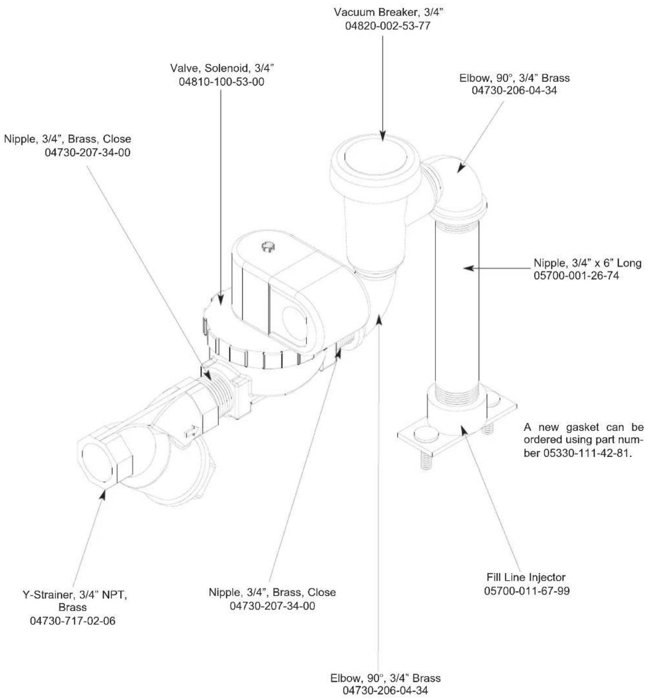
SECTION 5: PARTS SECTION
INCOMING PLUMBING ASSEMBLY (ELECTRIC & GAS HEATED MODELS)
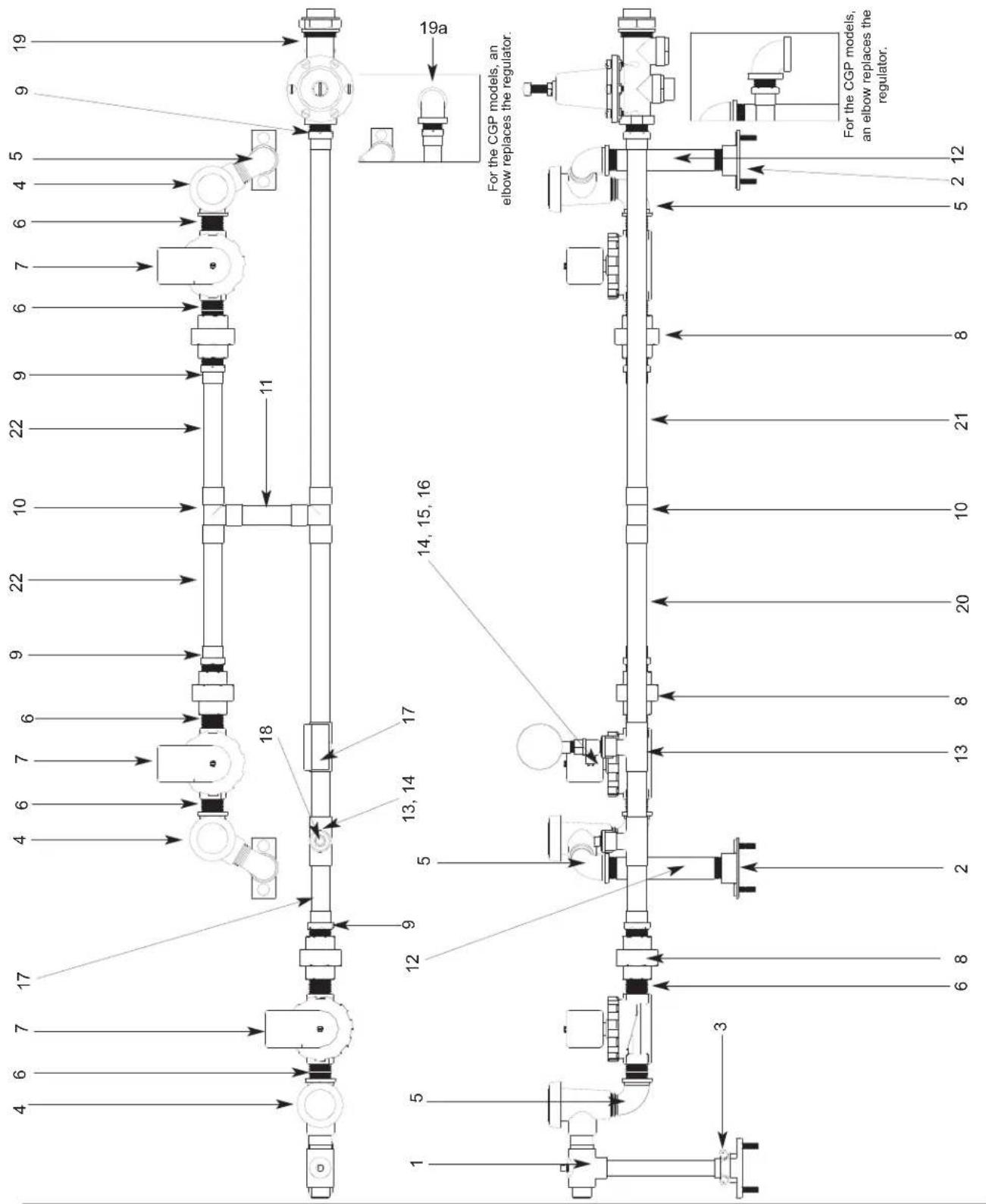
SECTION 5: PARTS SECTION
INCOMING PLUMBING ASSEMBLY(CONTINUED)
ITEM QTY DESCRIPTION Mfg. No.
1 1 Injector, Rinse Weldment (L-R all units) 05700-021-67-98
1 1 Injector, Rinse Weldment (R-L CGP units only) 05700-002-57-87
2 2 Fill Line, Injector 05700-011-67-99
3 3 Plug, 1/8" NPT, Brass 04730-209-07-37
4 3 Vacuum Breaker, 3/4" NPT, Brass 04820-002-53-77
5 5 Elbow, 3/4" NPT, Street, Brass 04730-206-04-34
6 6 Nipple, 3/4" NPT, Close, Brass 04730-207-34-00
7 3 Valve, Solenoid, 3/4" NPT, 110 Volt 04810-100-53-00
8 3 Union, 3/4" NPT, Brass
9 4 Adapter, 3/4" Male
10 2 Tee, Copper, 3/4" CU x CU x CU
11 1 Tube, Copper, 3/4" x 3" Long 05700-000-54-85
12 2 Nipple, 3/4" NPT, Brass, 6" Long 05700-001-26-74
13 2 Tee, Copper, 3/4" x 3/4" x 1/2" 04730-411-03-01
14 2 Adapter, Threaded, 1/4" 04730-401-41-01
15 1 Valve, Ball, Test Cock, 1/4" NPT 04810-011-72-67
16 1 Gauge, 0-100 PSI 06685-111-88-34
1 Decal, 15-25 PSI 09905-002-97-74
17 2 Tube, 3/4" x 2-13/16" Long 05700-011-72-72
18 1 Plug, 1/4" 04730-209-01-00
19 1 Regulator, Pressure, 3/4" NPT (Not used on CGP models) 06685-011-58-22
19a 1 Elbow, 3/4" 90° Brass (Used on CGP models only) 04730-206-13-00
20 1 Tube, 3/4" x 9" Long 05700-000-75-61
21 1 Tube, 3/4" x 16-1/4" Long 05700-011-31-48
22 2 Tube, 3/4" x 5-1/2" Long 05700-002-61-46
SECTION 5: PARTS SECTION
RINSE HEADER PLUMBING ASSEMBLY (CGP MODELS)
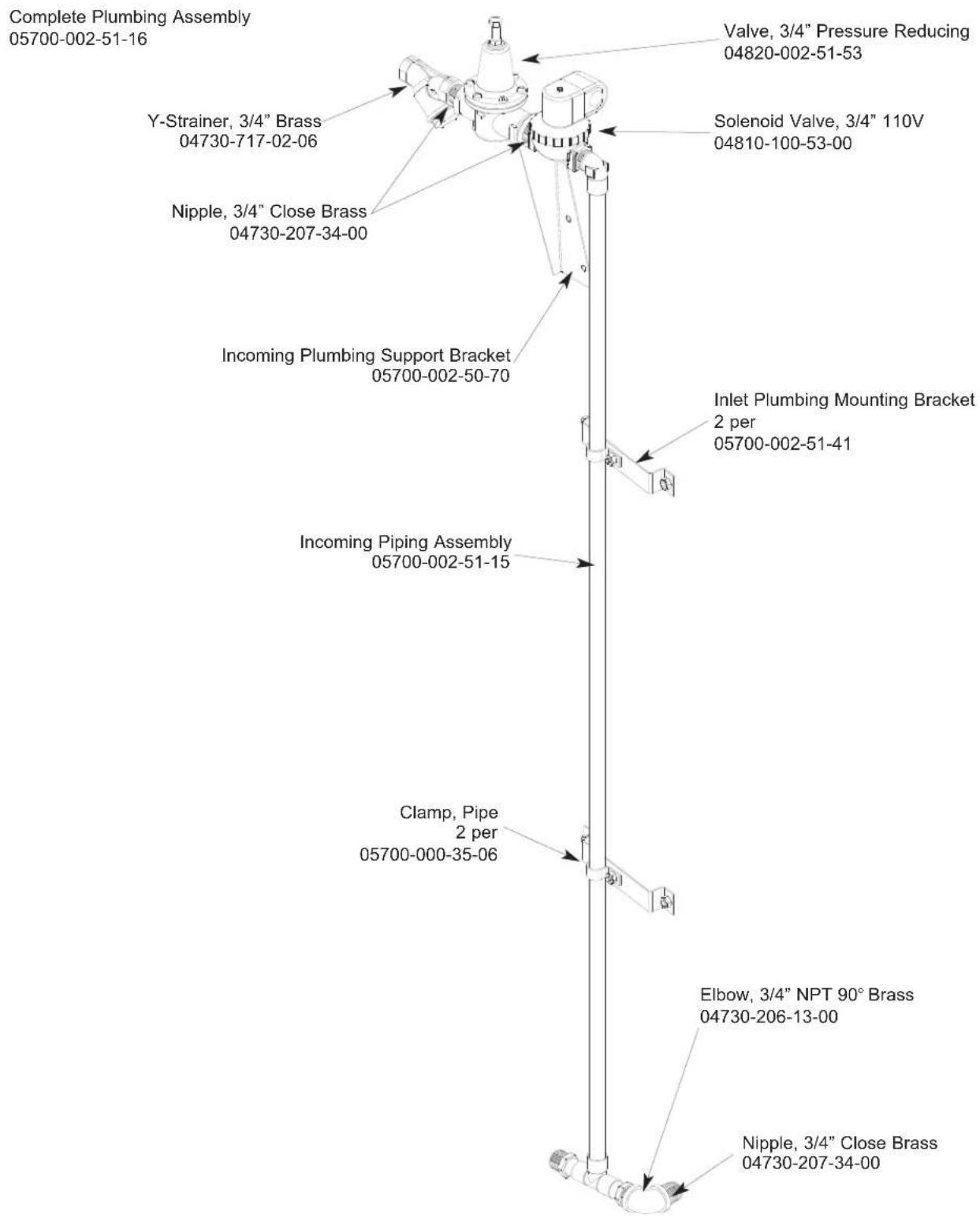
SECTION 5: PARTS SECTION
EXTERNAL ELECTRIC BOOSTER INCOMING PLUMBING ASSEMBLIES
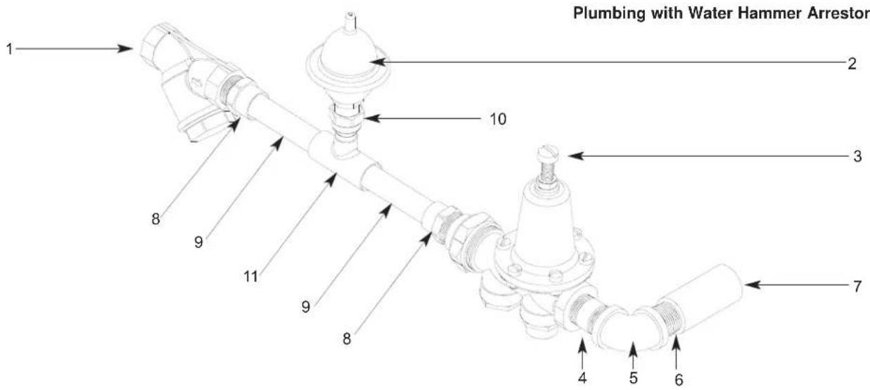
Plumbing without Water Hammer Arrestor
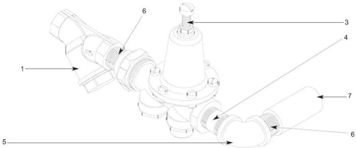
ITEM QTY DESCRIPTION Mfg. No.
1 - Y-Strainer, 3/4" NPT, Brass 04730-717-02-06
2 - Arrestor, Water Hammer, 1/2" NPT 06685-100-05-00
3 - Regulator, Pressure, 3/4" NPT, Brass 06685-011-58-22
4 - Nipple, 3/4" NPT x 2" Long, Brass 04730-207-46-00
5 - Elbow, Brass, 90°, 3/4" 04730-206-13-00
6 - Nipple, 3/4" NPT, Close, Brass 04730-207-34-00
7 - Coupling, 3/4" FNPT x 3/4" FNPT, Brass 04730-011-87-95
8 - Adapter, 3/4" Male 04730-401-11-01
9 - Tube, Copper, 3/4" x 3-7/16" Long
10 - Adapter, 1/2" NPT x Male
11 - Tee, Copper, 3/4" x 3/4" x 1/2"
05700-011-72-70
04730-401-07-01
04730-411-03-01
SECTION 5: PARTS SECTION
EXTERNAL ELECTRIC BOOSTER OPTION OUTLET PLUMBING
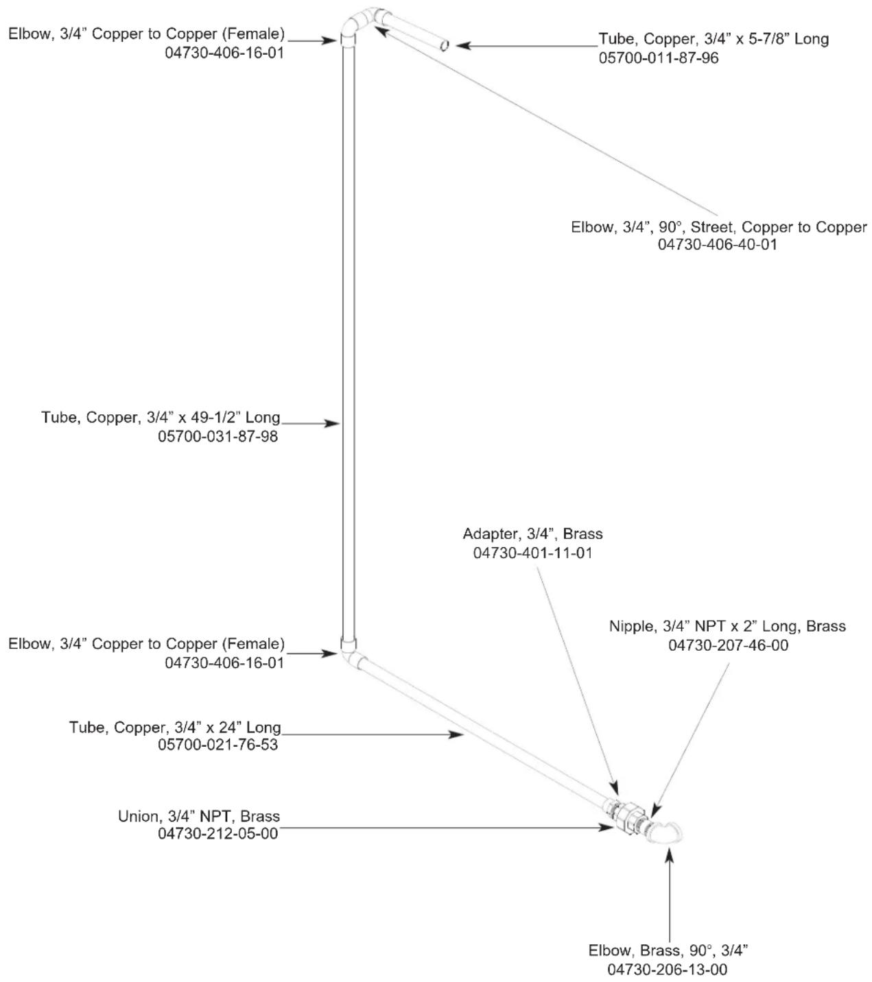
SECTION 5: PARTS SECTION
WATER HAMMER ARRESTOR OPTION/WATER PRESSURE REGULATOR KIT OPTION
WATER HAMMER ARRESTOR OPTION
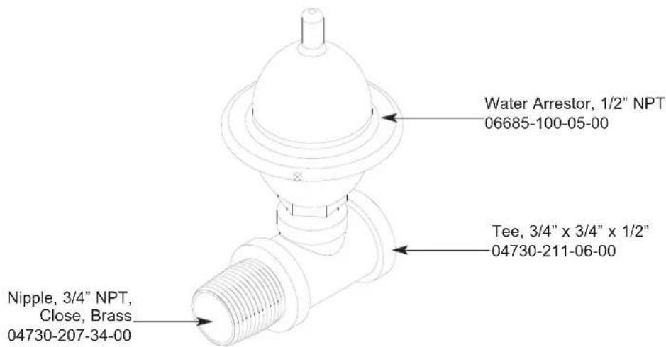
WATER PRESSURE REGULATOR WITH ARRESTOR KIT OPTION
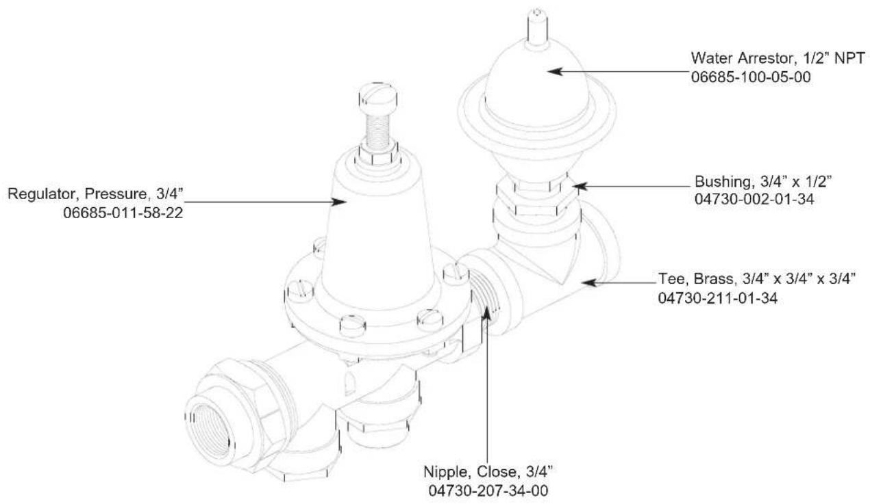
SECTION 5: PARTS SECTION
RINSE SOLENOID VALVE & VACUUM BREAKER REPAIR PARTS KITS
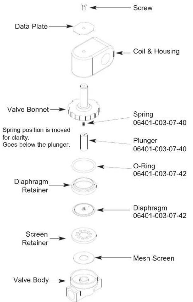
Complete 110 Volt Solenoid Valve Assembly, 3/4"
04810-100-53-00
Coil & Housing only, 3/4"
04810-200-01-18
Possible Problems:
- Pilot port extension #1 clogged. Clean hole.
- Hole #2 Clogged. Pass heated straight pin through hole.
natural_image
Simple diagram with concentric circles and arrows, no text or symbols present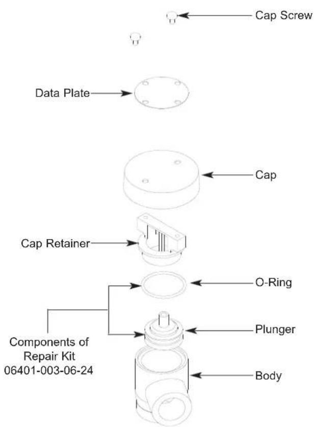
Complete Vacuum Breaker Assembly, 3/4" NPT 04820-002-53-77
DISASSEMBLY - These valves may be taken apart by unscrewing the bonnet and the enclosing tube assembly from the valve body assembly. After unscrewing, carefully lift off the bonnet and enclosing tube assembly. Don't drop the plunger. The o-ring seal and diaphragm cartridge can now be lifted out. Be careful not to damage the machined faces while the valve is apart.
TO REASSEMBLE - Place the diaphragm cartridge in the body with the pilot port extension UP. Hold the plunger with the synthetic seat against the pilot port. Make sure the o-ring is in place, then lower the bonnet and enclosing tube assembly over the plunger. Screw the bonnet assembly snugly down on the body assembly.
SECTION 5: PARTS SECTION
WASH TANK COIL ASSEMBLY
WASH TANK COIL ASSEMBLY
(LEFT TO RIGHT) (05700-041-88-31)
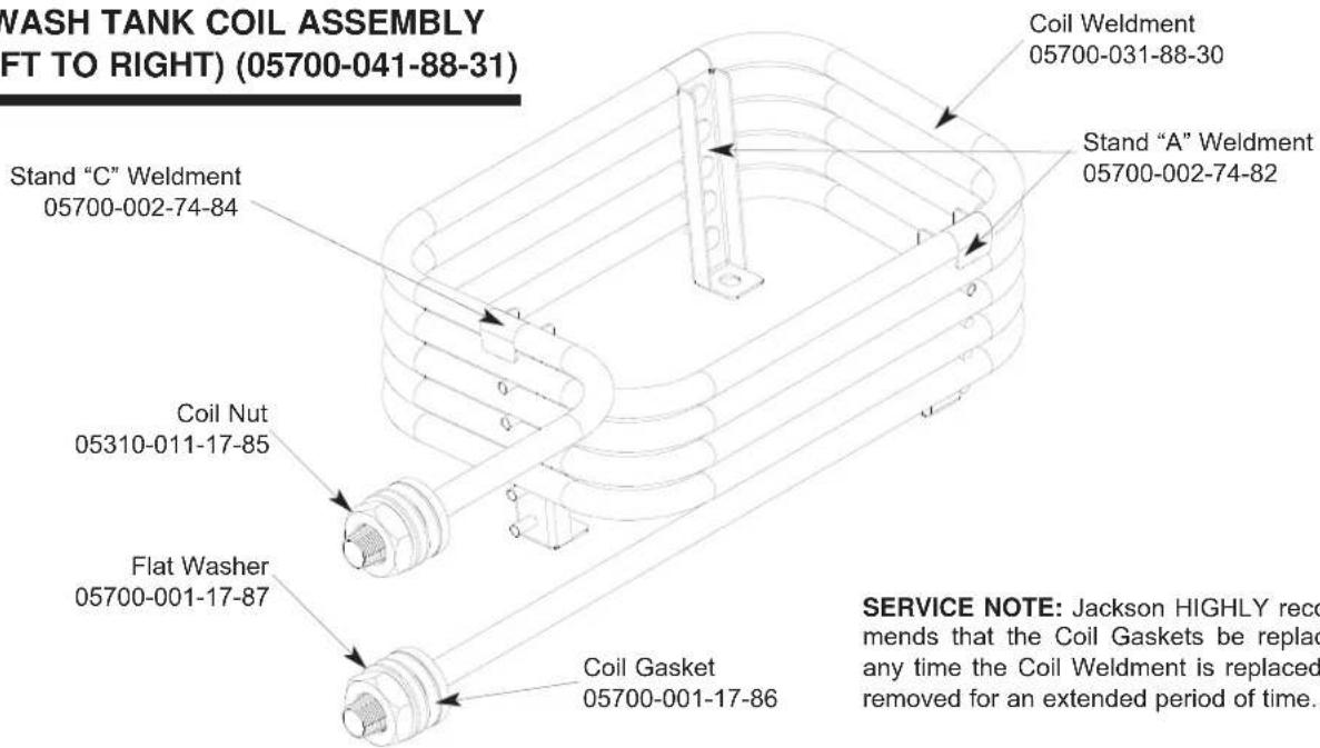
SERVICE NOTE: Jackson HIGHLY recommends that the Coil Gaskets be replaced any time the Coil Weldment is replaced or removed for an extended period of time.
WASH TANK COIL ASSEMBLY
(RIGHT TO LEFT) (05700-002-81-44)
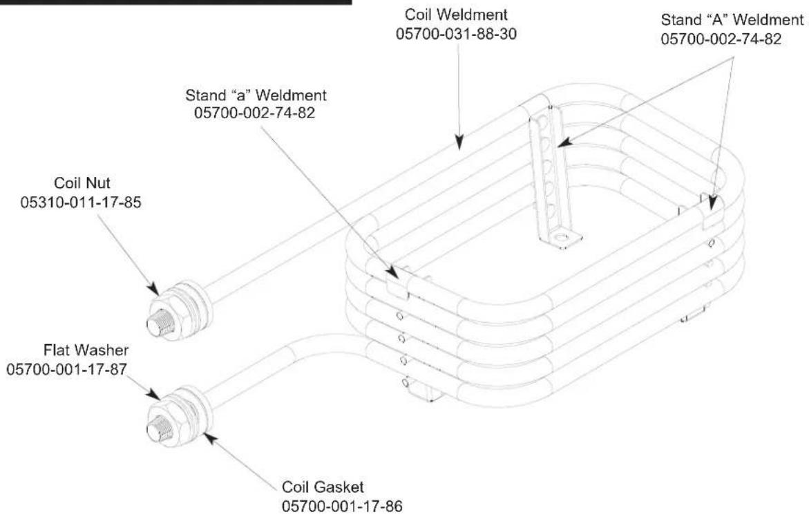
SECTION 5: PARTS SECTION
STEAM INLET PLUMBING ASSEMBLY (LEFT TO RIGHT MODELS)
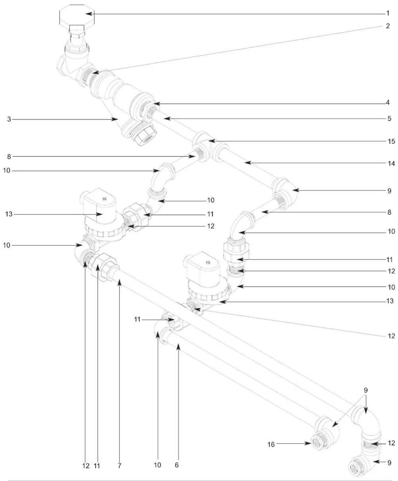
SECTION 5: PARTS SECTION
STEAM INLET PLUMBING ASSEMBLY (LEFT TO RIGHT MODELS) (CONTINUED)
ITEM QTY DESCRIPTION Mfg. No.
1 1 Valve, 1" Gate, Steam 04820-011-87-30
2 1 Nipple, 1" NPT, Close, Black Iron 04730-907-08-34
3 1 Y-Strainer, 1" NPT, Black Iron 04730-217-02-32
4 1 Reducer, 1" to 3/4" 04730-011-95-66
5 1 Nipple, 3/4" NPT x 6" Long, Black Iron 04730-907-01-34
6 1 Nipple, 3/4" NPT x 17" Long, Black Iron 05700-002-74-16
7 1 Nipple, 3/4" NPT x 26-1/2" Long, Black Iron 05700-002-74-17
8 2 Nipple, 3/4" NPT x 2" Long, Black Iron 04730-907-02-34
9 4 Elbow, 90^ , 3/4" NPT, Black Iron 04730-906-10-34
10 6 Elbow, 90°, 3/4" NPT, Street, Black Iron
11 4 Union, 3/4" NPT, Black Iron
12 5 Nipple, Close, 3/4" NPT, Black Iron
13 2 Valve, Solenoid, Steam, 120V, 3/4" NPT
14 1 Nipple, 3/4" NPT x 7" Long, Black Iron 05700-002-74-15
15 1 Tee, 3/4" NPT x 3/4" NPT x 3/4" NPT, Black Iron
16 2 Reducer, 3/4" NPT to 1/2" NPT, Black Iron
04730-011-87-37
04730-912-01-00
04730-907-04-00
04820-011-87-39
04730-002-74-14
04730-911-02-34
SECTION 5: PARTS SECTION
STEAM INLET PLUMBING ASSEMBLY (RIGHT TO LEFT MODELS)
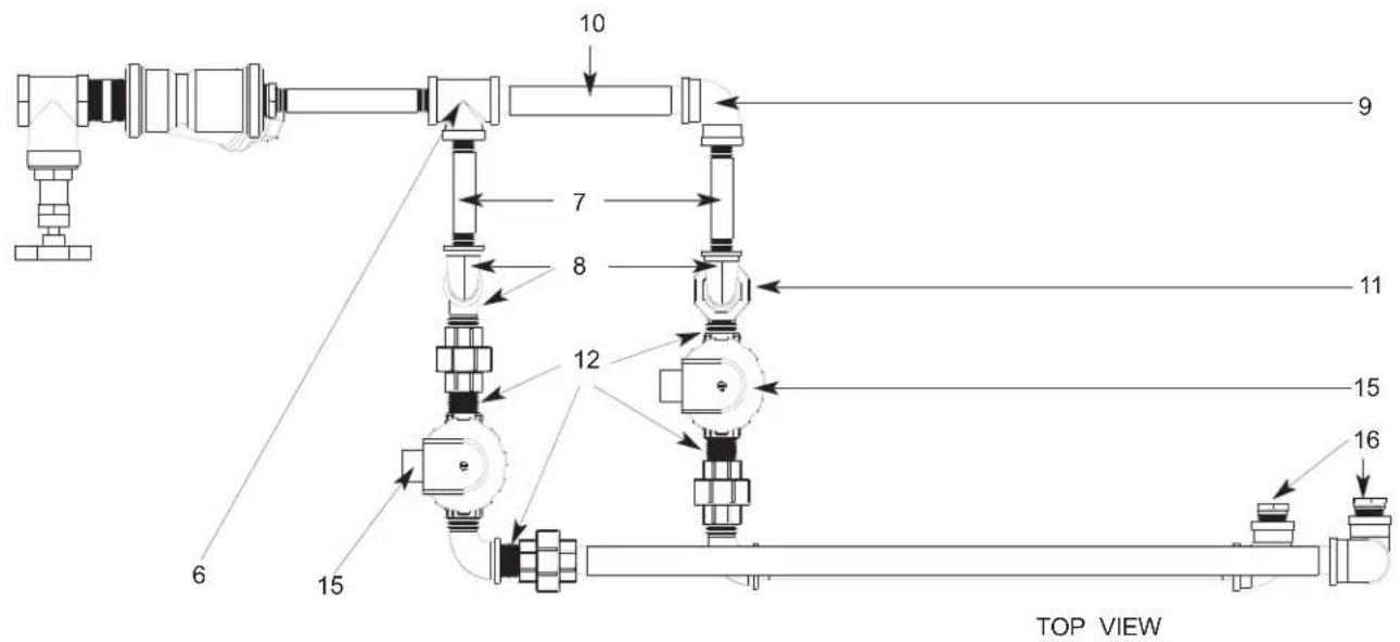
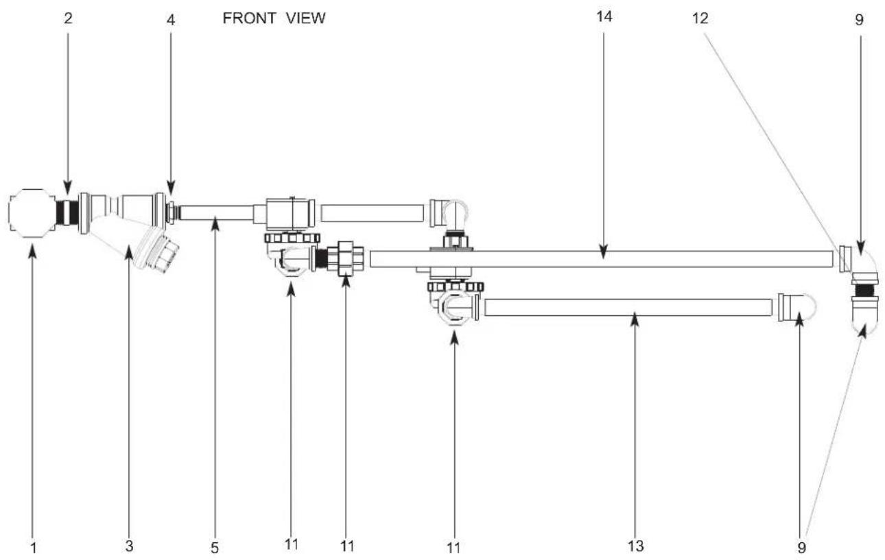
SECTION 5: PARTS SECTION
STEAM INLET PLUMBING ASSEMBLY (RIGHT TO LEFT MODELS)(CONTINUED)
ITEM QTY DESCRIPTION Mfg. No.
1 1 Valve, 1" Gate 04820-011-87-30
2 1 Nipple, 1" NPT, Close, Black Iron 04730-907-08-34
3 1 Y-Strainer, 1" NPT, Black Iron 04730-217-02-32
4 1 Reducer, 1" NPT to 3/4" NPT 04730-011-95-66
5 1 Nipple, 3/4" NPT x 6" Long, Black Iron 04730-907-01-34
6 1 Tee, 3/4" x 3/4" x 3/4", Black Iron 04730-002-74-14
7 2 Nipple, 3/4" NPT x 4" Long, Black Iron 04730-907-02-34
8 6 Elbow, Street, 3/4" NPT, 90°, Black Iron 04730-011-87-37
9 4 Elbow, 3/4" NPT, 90°, Black Iron
10 1 Nipple, 3/4" NPT x 7" Long, Black Iron 05700-002-74-15
11 4 Union, 3/4" NPT, Black Iron
12 5 Nipple, 3/4" NPT, Close, Black Iron
13 1 Nipple, 3/4" NPT x 17" Long, Black Iron
14 1 Nipple, 3/4" NPT x 26-1/2" Long, Black Iron
15 2 Valve, Solenoid, Steam, 3/4" NPT, 120V
16 2 Reducer, 3/4" NPT to 1/2" NPT
04730-906-10-34
04730-912-01-00
04730-907-01-00
05700-002-74-16
05700-002-74-17
04820-011-87-39
04730-911-02-34
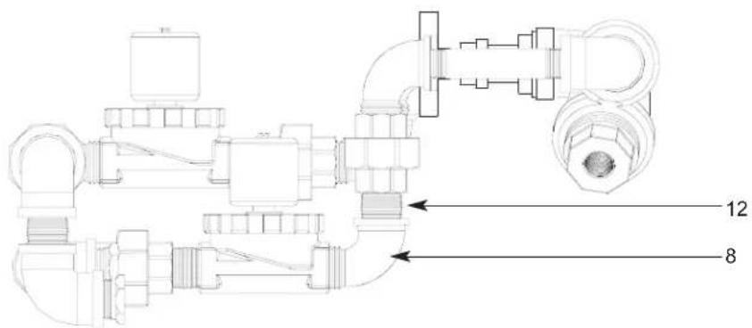
RIGHT SIDE VIEW
SECTION 5: PARTS SECTION
STEAM OUTLET PLUMBING (LEFT TO RIGHT)
TOP PLUMBING
05700-002-81-66
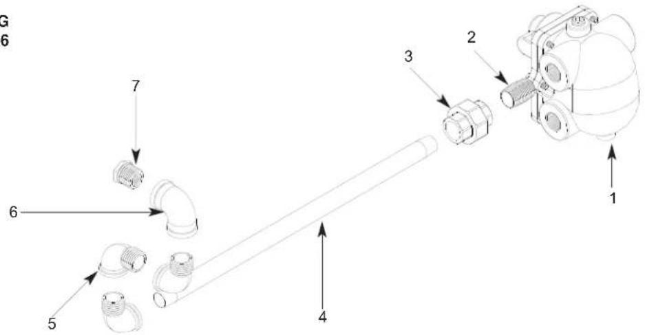
ITEM QTY DESCRIPTION Mfg. No.
1 - Trap, Steam, 3/4" NPT 06680-500-02-77
2 - Nipple, Close, 3/4" NPT, Black Iron 04730-907-01-00
3 - Union, 3/4" NPT, Black Iron 04730-912-01-00
4 - Nipple, 3/4" x 18" Long, Black Iron 05700-002-74-10
5 - Elbow, 90° Street, 3/4" NPT, Black Iron 04730-011-87-37
6 - Elbow, 90°, 3/4" NPT, Black Iron 04730-906-10-34
7 - Reducer, 3/4" NPT to 1/2" NPT Black Iron 04730-911-02-34
8 - Nipple, 3/4" NPT x 26-1/2" Long, Black Iron
04730-911-02-34
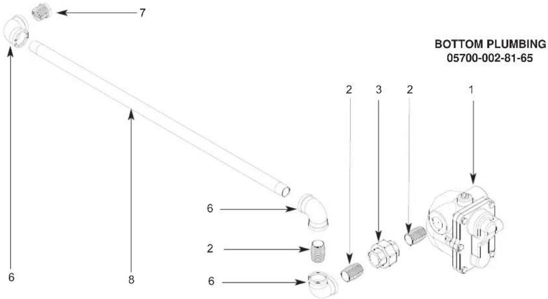
SECTION 5: PARTS SECTION
SECTION 5: PARTS SECTION
AJ-86 GAS COIL ASSEMBLY (CGP MODELS)
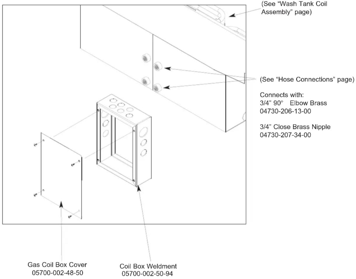
Other items used but not shown.
ITEM QTY DESCRIPTION Mfg. No.
1 1 Thermostat, High Limit 05930-011-49-43
2 1 Gasket 05330-200-02-70
3 1 Terminal Board 05940-002-78-97
4 1 Thermostat Bracket 05700-011-81-64
5 1 Decal, Thermostat Regulating 09905-011-84-31
6 1 Thermostat, Wash Regulating 06401-140-00-32
7 1 Fitting, 1/4", Imperial Brass 05310-924-02-05
SECTION 5: PARTS SECTION
TANK, RINSE BOOSTER (CGP MODELS ONLY)
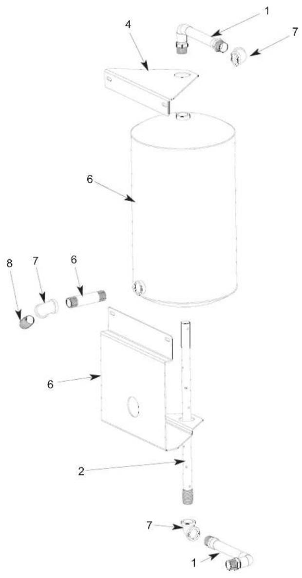
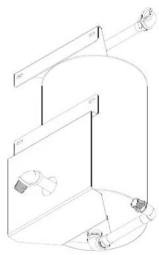
natural_image
Technical line drawing of a cylindrical tank with internal components and a valve, no text or symbols presentBOTTOM ANGLED VIEW
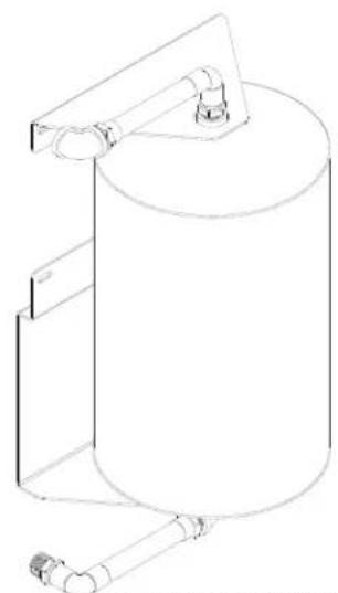
natural_image
Line drawing of a cylindrical tank with attached support structure (no text or symbols)TOP ANGLED VIEW
ITEM QTY DESCRIPTION Mfg. No.
1 2 Plumbing Assembly, Inlet/Discharge, Rinse Tank 05700-002-51-24
2 1 Tube, Dispersion Weldment 05700-002-46-16
3 1 Tank, GP Rinse 05700-002-45-05
4 1 Bracket, Upper Rinse Tank 05700-002-67-13
5 1 Bracket, Lower Rinse Tank 05700-002-67-14
6 1 Nipple, 3/4" NPT x 4" Long 04730-207-05-00
7 3 Elbow, 3/4" NPT, 90° Brass 04730-206-13-00
8 1 Nipple, 3/4" NPT x Closed Brass 04730-207-34-00
SECTION 5: PARTS SECTION
RECIRCULATING PUMP ASSEMBLY (CGP MODELS ONLY)
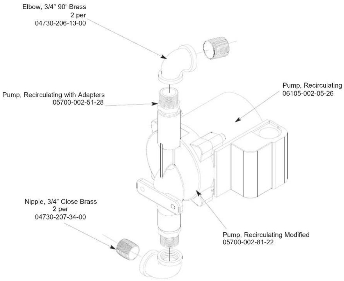
Used only on AJ-86CGP left to right units.
natural_image
Simple line drawing of a rounded rectangle with four vertical oval cutouts at the bottom corners (no text or symbols)Mounting Bracket
05700-002-25-74
Used on AJ-64CGP, AJ-86CGP, AJ-100CGP units right to left units and the AJ-64CGP left to right unit.
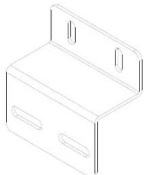
natural_image
Line drawing of a rectangular box with two side slots and a top shelf (no text or symbols)Mounting Bracket
05700-002-23-61
SECTION 5: PARTS SECTION
HOSE CONNECTIONS (CGP MODELS ONLY)
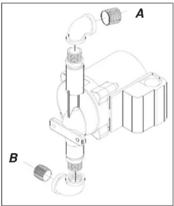
Recirculating Pump Assembly
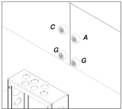
Gas Coil Weldment Rinse Booster Tank
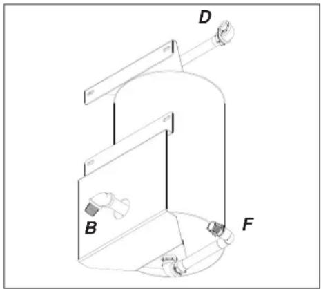
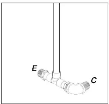
natural_image
Simple line drawing of a pipe fitting with labeled points E and C (no text or symbols beyond labels)Rinse Header Plumbing Assembly
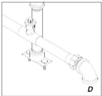
natural_image
Technical line drawing of a pipe fitting with mounting flanges and a central support (no text or symbols)Wash/Fill Plumbing Assembly
HOSE ASSEMBLIES
AJ-86CGP (L-R & R-L)
AJ-100CGP (L-R)
*Each hose assembly includes 2, 3/4" Pushlock Fittings part number 04730-011-94-00.
A - Hose, Recirculating Discharge 05700-002-52-74 05700-002-52-76
B - Hose, Recirculating Pump Suction 05700-002-52-75 05700-002-51-38
C - Hose, Wash Coil Assembly 05700-002-52-76 04720-011-94-10 (66")
D - Hose, Wash/Fill Supply 05700-003-03-97 05700-003-03-99
E - Hose connection to existing gas booster outlet fitting.
F - Hose connection to existing gas booster inlet fitting.
G - Hose, Coil Recirculating 05700-002-17-71 05700-002-17-71
Gas Booster Connection Kit 05700-002-51-73 includes:
18 Feet of 3/4" Hose
4 - 3/4" Push Lock Fittings
SECTION 5: PARTS SECTION
AJ-64 DRAIN PLUMBING ASSEMBLY
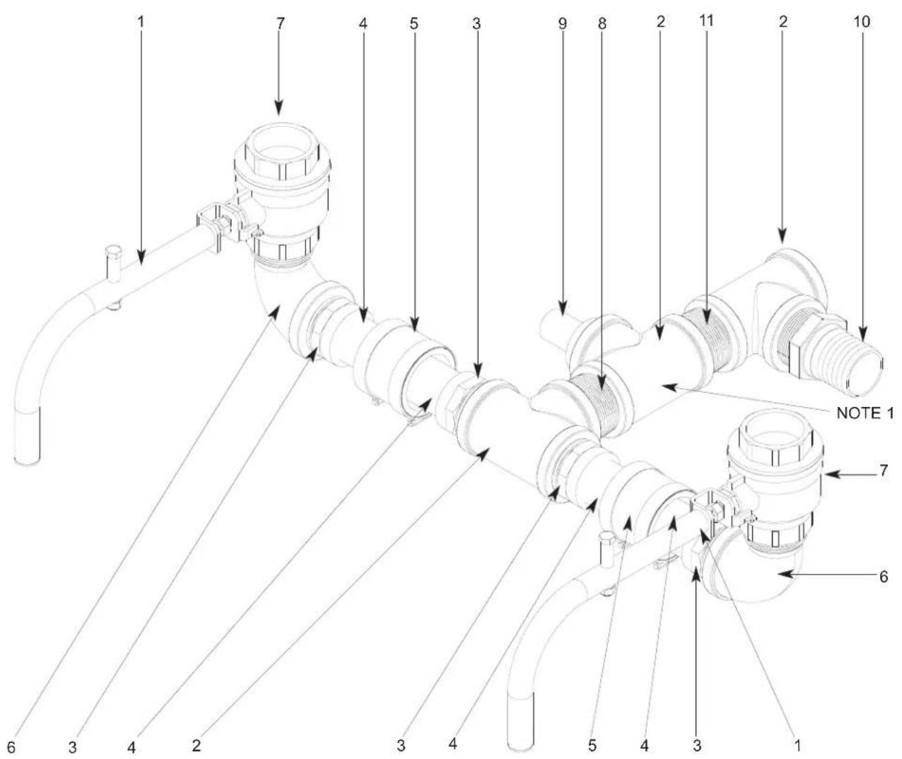
ITEM QTY DESCRIPTION Mfg. No.
1 2 Ball Valve Handle Assembly 05700-021-84-74
1 Spacer (Not Shown) 05700-002-87-05
2 3 Tee, Brass, 1-1/2" x 1-1/2" x 1-1/2" 04730-011-69-93
3 4 Adapter, 1-1/2" 04730-401-25-01
4 4 Tube, Copper, 1-1/2" OD x 2" Long 05700-011-87-16
5 2 Connector, No-Hub, 1-1/2" 04720-604-06-00
6 2 Elbow, 1-1/2", Street, Brass, 90° 04730-206-32-00
7 2 Valve, Ball, 1-1/2" NPT 04820-111-71-46
8 1 Nipple, 1-1/2" NPT, Brass, Close 04730-207-40-00
9 1 Rinse Nipple Weldment
10 1 Fitting, Barbed, 1-1/2" NPT x 1-1/2"
11 1 Nipple, Brass, 1-1/2" x 3" Long
05700-021-84-61
04730-011-69-92
04730-011-87-04
NOTE 1: Component is shown for installation in a Right-to-Left model; component is rotated 180 degrees for Left-to-Right units.
SECTION 5: PARTS SECTION
AJ-86 & AJ-100 DRAIN PLUMBING ASSEMBLY (LEFT TO RIGHT MODELS)
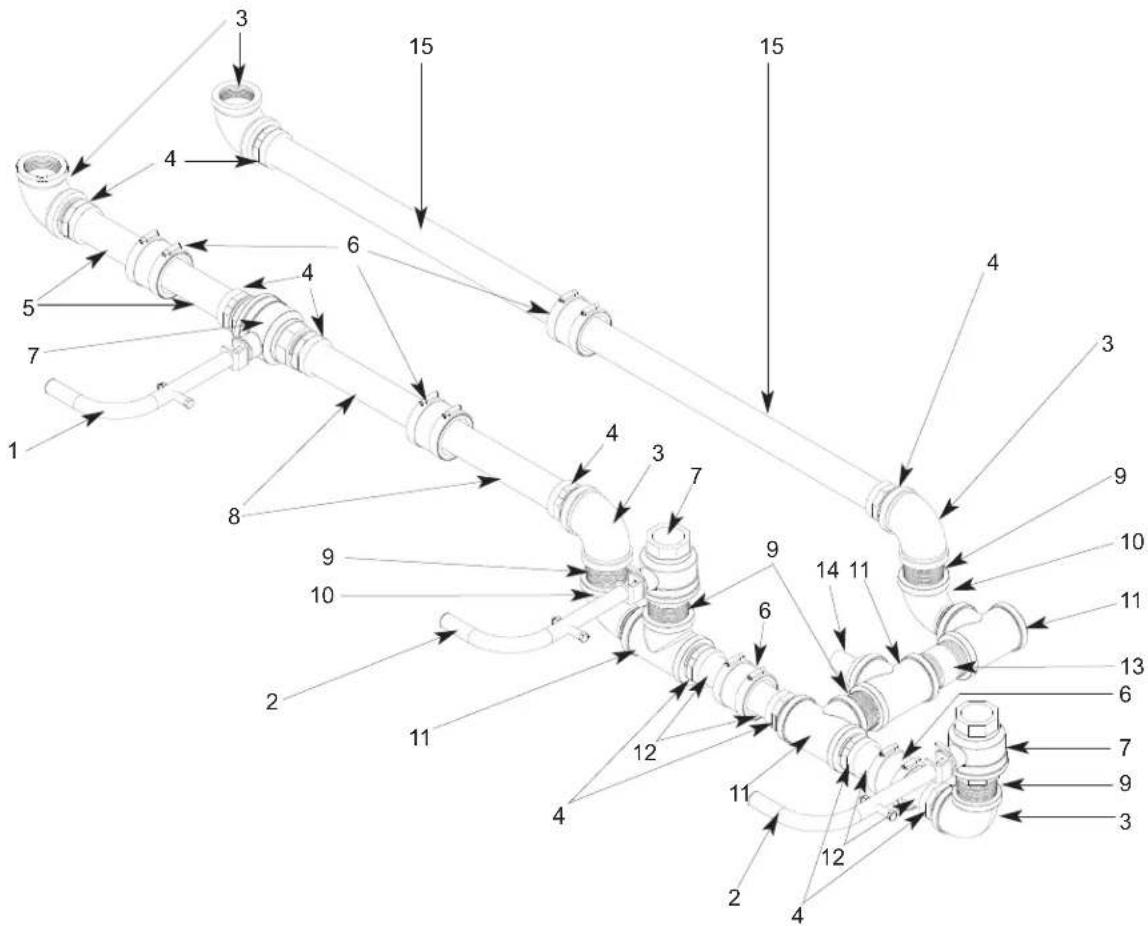
ITEM QTY DESCRIPTION Mfg. No.
1 1 Ball Valve Handle 05700-021-84-74
Spacer (Not Shown) 05700-002-87-05
2 2 Ball Valve Handle 05700-021-83-53
Spacer (Not Shown) 05700-002-87-05
3 5 Elbow, 1-1/2" FNPT, 90° Brass 04730-011-73-77
4 10 Adapter, 1-1/2" 04730-401-25-01
5 2 Tube, Copper, 1-1/2" OD x 4-7/16" Long (AJ-86 Models) 05700-011-84-22
2 Tube, Copper, 1-1/2" OD x 5-1/4" Long (AJ-100 Models) 05700-002-79-12
6 5 Connector, No-H UB, 1-1/2" 04720-604-06-00
7 3 Ball Valve, 1-1/2" 04820-011-71-46
8 2 Tube, Copper, 1-1/2" OD x 7-3/4" Long (AJ-86 Models)
2 Tube, Copper, 1-1/2" OD x 13-3/4" Long (AJ-100 Models)
9 5 Nipple, 1-1/2" NPT, Brass, Close
10 2 Elbow, 1-1/2" NPT, Brass, Street
11 4 Tee, Brass, 1-1/2" NPT
12 4 Tube, Copper, 1-1/2" OD x 2" Long
13 1 Nipple, Brass, 1-1/2" NPT x 3" Long
14 1 Rinse Nipple Weldment
15 2 Tube, Copper, 1-1/2" OD x 20-1/8" Long (AJ-86 Models) 05700-021-84-29
2 Tube, Copper, 1-1/2" OD x 27-1/2" Long (AJ-100 Models)
05700-021-84-24
05700-021-88-17
04730-207-40-00
04730-206-32-00
04730-011-69-93
05700-011-87-16
04730-011-87-04
05700-021-84-61
05700-021-84-28
SECTION 5: PARTS SECTION
AJ-86 & AJ-100 DRAIN PLUMBING ASSEMBLY (RIGHT TO LEFT MODELS)
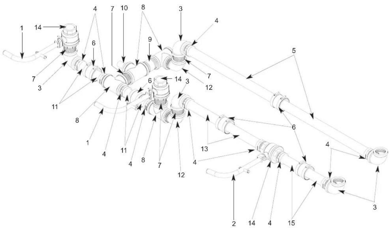
ITEM QTY DESCRIPTION Mfg. No.
1 2 Ball Valve Handle Assembly 05700-021-83-53
Spacer (Not Shown) 05700-002-87-05
2 1 Ball Valve Handle Assembly 05700-021-84-74
Spacer (Not Shown) 05700-002-87-05
3 5 Elbow, 1-1/2" FNPT, 90°, Brass 04730-011-73-77
4 10 Adapter, 1-1/2" NPT 04730-401-25-01
5 2 Tube, 1-1/2" x 20-1/8" Long (AJ-86 Models) 05700-021-84-29
2 Tube, Copper, 1-1/2" x 27-1/2" Long (AJ-100 Models) 05700-021-84-28
6 5 Connector, No Hub, 1-1/2" 04720-604-06-00
7 5 Nipple, 1-1/2" NPT, Brass, Close 04730-207-40-00
8 4 Tee, 1-1/2" NPT x 1-1/2" NPT x 1-1/2" NPT
9 1 Nipple, 1-1/2" NPT x 3 Long, Brass
10 1 Rinse Nipple Weldment
11 4 Tube, Copper, 1-1/2" x 2" Long
12 2 Elbow, 1-1/2" NPT, 90°, Brass, Street
13 2 Tube, Copper, 1-1/2" x 7-3/4" Long (AJ-86 Models)
2 Tube, Copper, 1-1/2" x 13-3/4" Long (AJ-100 Models) 05700-021-88-17
14 3 Valve, Ball, 1-1/2" NPT
15 2 Tube, Copper, 1-1/2" x 4-7/16" Long (AJ-86 Models)
2 Tube, Copper, 1-1/2" x 5-1/4" Long (AJ-100 Models)
04730-011-69-93
04730-011-87-04
05700-021-84-61
05700-011-87-16
04730-206-32-00
05700-021-84-24
04820-011-71-46
05700-011-84-22
05700-002-79-12
SECTION 5: PARTS SECTION
DRAIN VALVE HANDLE ASSEMBLY/DRAIN QUENCH SYSTEM
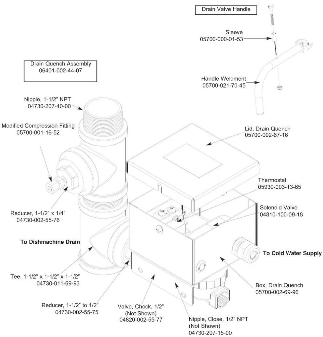
From the existing drain, attach the two additional Tees using the 1-1/2" NPT Close Nipples. Tighten the Reducers into the Tees as shown above. Attach the Modified Compression Fitting into the 1-1/2" to 1/4" Reducer. Position the bulb of the thermostat so that it rests approximately 1/4" from the bottom of the Tee. Tighten the Modified Compression Fitting as required. Attach to the incoming cold water line. Use pipe dope or thread tape as required to prevent any leaks.
SECTION 5: PARTS SECTION
MOTOR ASSEMBLIES
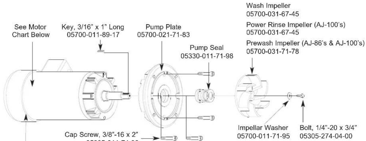
Clamp (Not Shown) 04730-002-32-15
WASH MOTOR CHART
| Volts | Phase Hz | Part Number |
| 208 - 230 | 1 60 06105-021-70-57 | |
| 200 - 230 | 3 60 06105-121-70-58 | |
| 460 | 3 60 06105-121-70-58 |
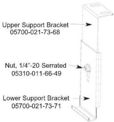

natural_image
Simple circular diagram with four corner dots, no text or symbols presentMotor Mounting Gasket 05330-011-71-62
PREWASH MOTOR CHART
| Model(s) | Volts | Phase | Hz | Part Number |
| AJ-86's 208 1 60 | 06105-121-70-55 | |||
| 230 1 60 06105-121-70-55 | ||||
| 208 3 60 06105-121-70-56 | ||||
| 230 3 60 06105-121-70-56 | ||||
| 460 3 60 06105-121-70-56 | ||||
| AJ-100's 208 1 60 | 06105-121-70-57 | |||
| 230 1 60 06105-121-70-57 | ||||
| 208 3 60 06105-121-70-58 | ||||
| 230 3 60 06105-121-70-58 | ||||
| 460 3 60 06105-121-70-58 |
POWER RINSE MOTOR CHART
| Model(s) | Volts | Phase | Hz | Part Number |
| AJ-100's 208 1 60 | 06105-121-70-57 | |||
| 230 1 60 | 06105-121-70-57 | |||
| 208 3 60 | 06105-121-70-58 | |||
| 230 3 60 | 06105-121-70-58 | |||
| 460 3 60 | 06105-121-70-58 |
SECTION 5: PARTS SECTION PREWASH & WASH PUMP WELDMENT
Prewash Strainer Bracket
05700-021-74-94
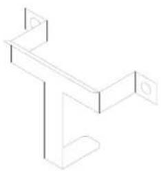
natural_image
Pure 3D line drawing of a Y-shaped mechanical bracket (no text or symbols)Prewash Intake Strainer Weldment
05700-021-74-96
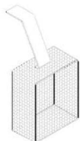
natural_image
Isometric line drawing of a 3D rectangular prism with a protruding rod (no text or symbols)Intake Suction Scoop Weldment
05700-021-87-60
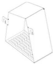
natural_image
Line drawing of a 3D box with internal grid structure (no text or symbols)The pump weldment is secured to the pump plate (through the actual tub wall) using the following fasteners:
Nut, Hex, 3/8"-16 05310-276-01-00
Washer, Flat, 3/8" 05311-176-01-00
Lockwasher, Split, 3/8" 05311-276-01-00
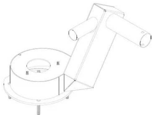
natural_image
Technical line drawing of a mechanical assembly with cylindrical components and mounting feet (no text or symbols)The power rinse pump weldment is a single part. Separate pieces of the weldment are not available for purchase.
Power Rinse Pump Weldment (AJ-100's)
05700-031-81-47
natural_image
Technical line drawing of a mechanical component with flanged ends and a cylindrical shaft (no text or symbols)The prewash pump weldment is a single part. Separate pieces of the weldment are not available for purchase.
Prewash Pump Weldment
AJ-86/AJ-100 Left to Right models: 05700-002-10-62
natural_image
Technical line drawing of a mechanical component with cylindrical and flanged features (no text or symbols)The wash pump weldment is a single part. Separate pieces of the weldment are not available for purchase. The weldment is used for the wash pump in all models covered in this manual. The weldment may be ordered using part number 05700-041-68-88.
natural_image
Pure technical line drawing of a mechanical component with no text, numbers, or symbolsThe prewash pump weldment is a single part. Separate pieces of the weldment are not available for purchase.
Prewash Pump Weldment
AJ-86/AJ-100 Right to Left models: 05700-002-11-96
SECTION 5: PARTS SECTION
PREWASH & UPPER WASH ARM ASSEMBLIES
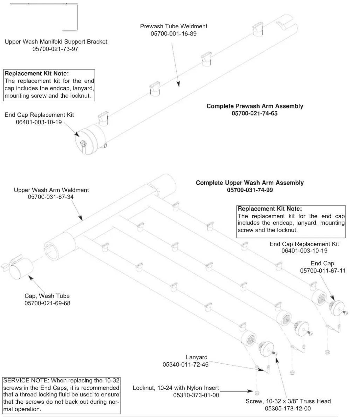
SECTION 5: PARTS SECTION
LOWER WASH ARM ASSEMBLY
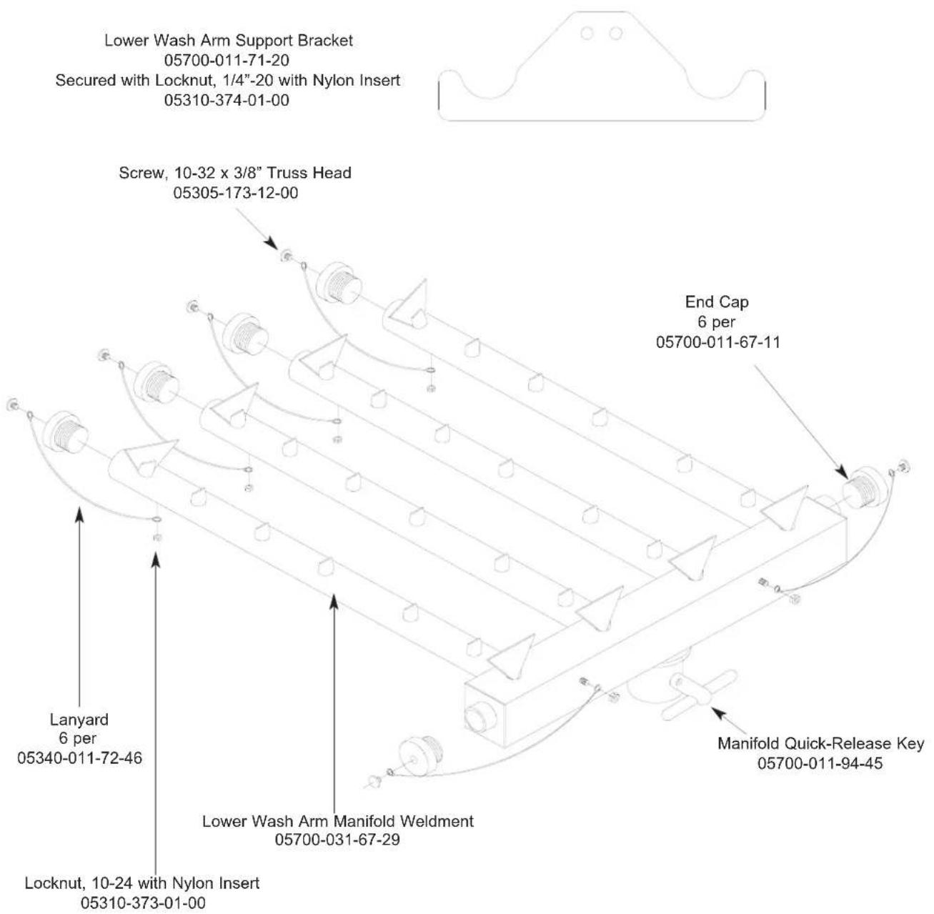
Complete Lower Wash Arm Assembly 05700-031-74-66
SERVICE NOTE: When replacing the 10-32 screws in the End Caps, it is recommended that a thread locking fluid be used to ensure that the screws do not back out during normal operation.
SECTION 5: PARTS SECTION
UPPER & LOWER POWER RINSE ARM ASSEMBLIES
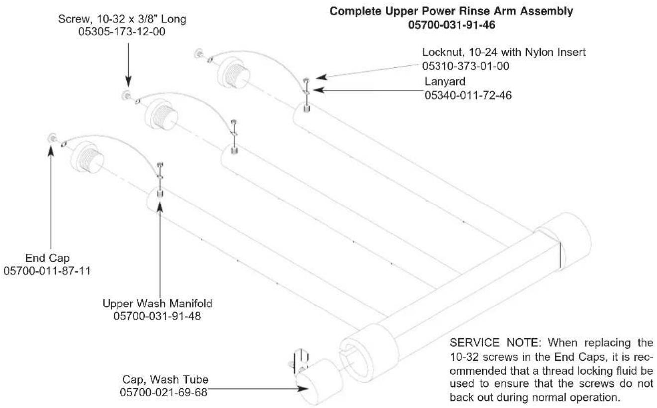
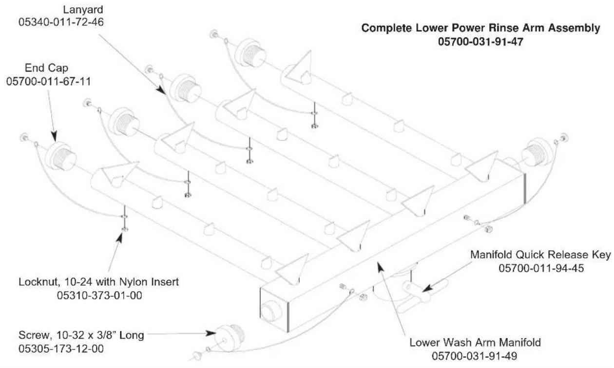
SECTION 5: PARTS SECTION
FINAL RINSE ASSEMBLY
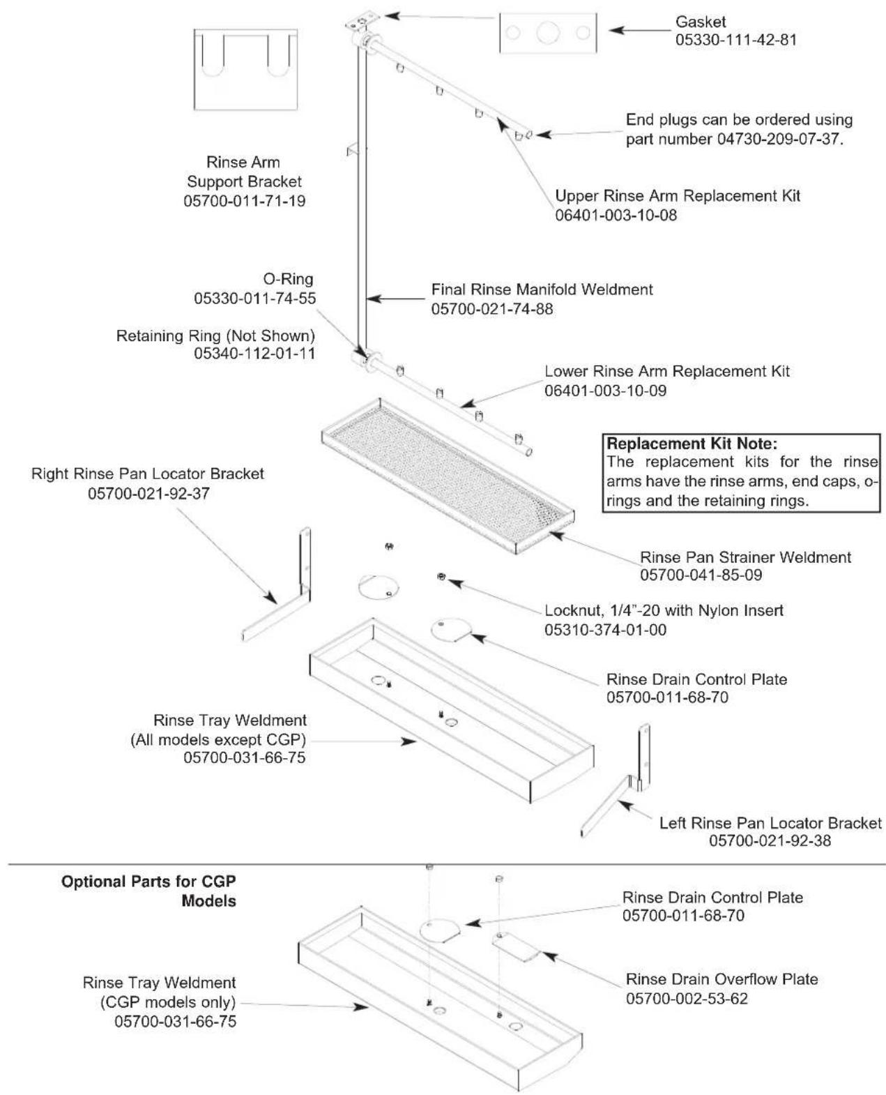
SECTION 5: PARTS SECTION
DRIVE ASSEMBLY
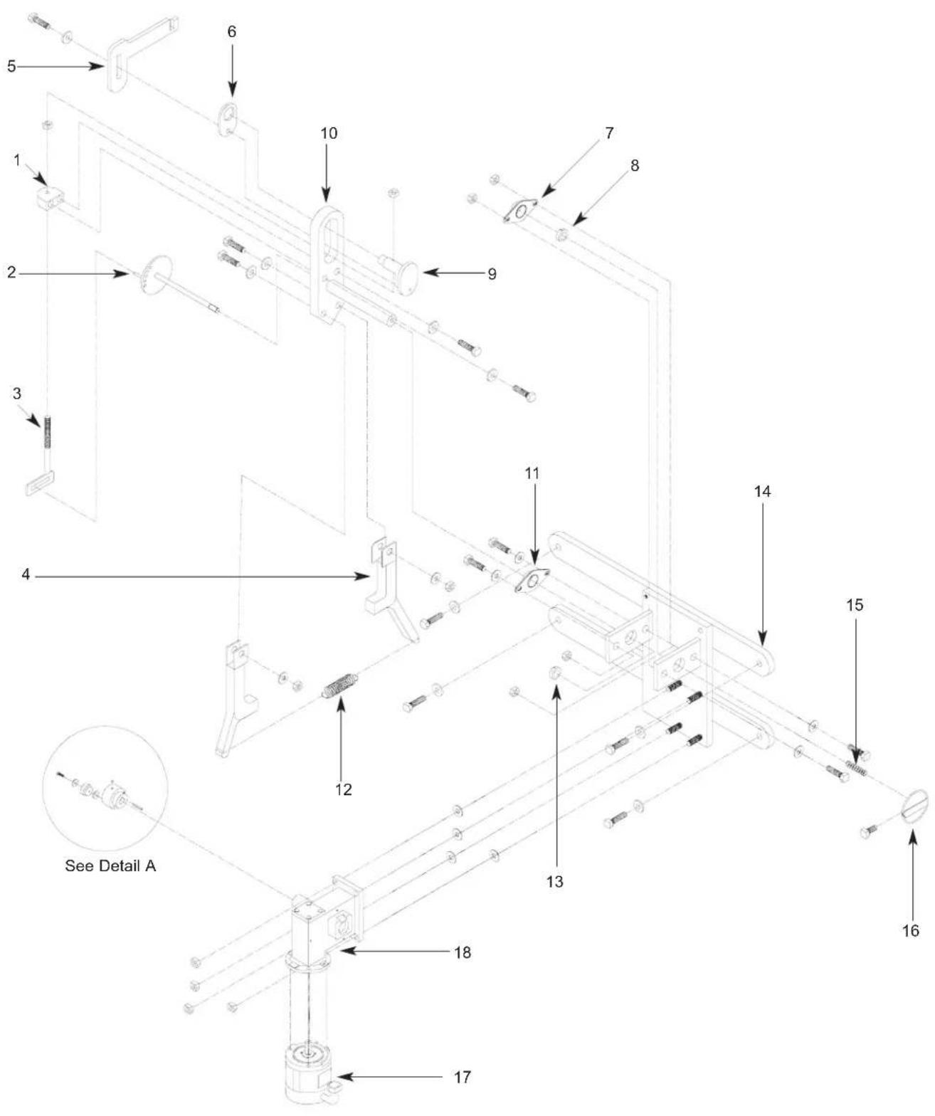
SECTION 5: PARTS SECTION
DRIVE ASSEMBLY (CONTINUED)
ITEM QTY DESCRIPTION Mfg. No.
| 1 | 1 | Drive Plate and Rod Weldment | 05700-021-67-44 |
| Replacement Kit with Expansion Legs | 06401-021-86-80 | ||
| Replacement Kit with Expansion Legs/Adjuster Crank | 06401-011-94-54 | ||
| 2 | 1 | Adjuster Crank Assembly | 05700-021-69-95 |
| 3 | 1 | Sketch Yoke Weldment Replacement Kit | 06401-003-08-48 |
| 4 | 2 | Coupling & Expansion Leg Weldment | 09515-003-58-12 |
| 5 | 1 | Pawl Bar Drive Linkage Casting | 09515-021-87-73 |
| 6 | 1 | Spacer Plate | 05700-011-67-58 |
| 7 | 2 | Pillow Block Replacement Kit | 06401-003-08-50 |
| 8 | 2 | Shaft Collar | 05700-011-89-18 |
| 9 | 1 | Drive Socket | 05700-021-67-39 |
| 10 | 1 | Drive Plate | 05700-021-67-42 |
| 11 | 2 | Pillow Block | 03120-021-71-87 |
| 12 | 1 | Drive Spring | 05315-011-83-51 |
| 13 | 2 | Shaft Collar | 05700-011-89-18 |
| 14 | 1 | Drive Motor Mounting Bracket | 05700-031-73-56 |
| 15 | 1 | Adjuster Spring 05315-011-71-90 | |
| 16 | 1 | Adjusting Handle Weldment | 05700-021-72-28 |
| 17 | 1 | Drive Motor Replacement Kits | |
| 1 | Drive Motor (208-230 Volt, 60 Hz, Single Phase Models) | 06401-003-08-42 | |
| Drive Motor (208-230 Volt, 60 Hz, Three Phase Models) | 06401-003-08-40 | ||
| 18 | 1 | Gear Drive | 06105-011-71-88 |
| 19 | 1 | Roller Bearing | 03120-011-71-81 |
| 20 | 1 | Drive Hub | 05700-011-67-97 |
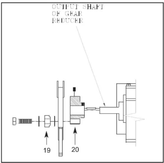
Detail A
natural_image
Pure technical line drawing of a 3D mechanical part with no text, numbers, or symbolsFront Drive Motor Cover
Replacement Kit
06401-003-11-64
natural_image
Pure technical line drawing of a vertical L-shaped structure without any text, numbers, or symbolsRear Drive Motor Cover
Replacement Kit
06401-003-10-18
Replacement Kits Notes:
The replacement kits for the drive motor covers come with the weldments and the mounting hardware.
SECTION 5: PARTS SECTION
DOOR ASSEMBLIES
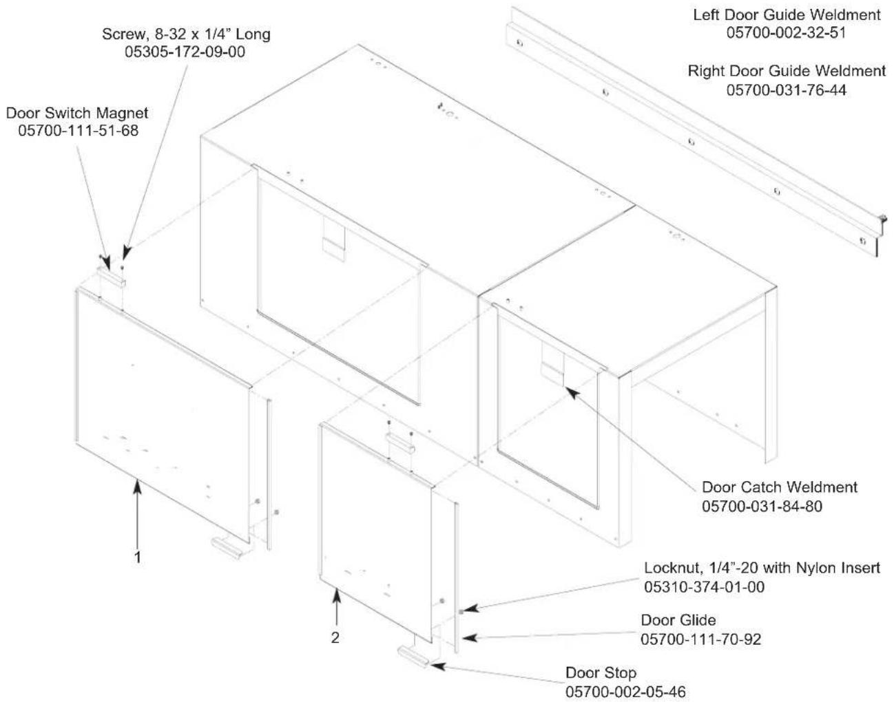

natural_image
Pure horizontal and vertical lines without any text, numbers, or symbolsWash Door Hood Support: 05700-031-84-13 Prewash Door Hood Support: 05700-031-84-14
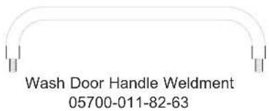
Prewash Door Handle Weldment 05700-011-80-45
ITEM QTY DESCRIPTION Mfg. No.
1 1 Wash Door Weldment 05700-031-83-39
1 1 Wash Door Weldment (No Emboss) 05700-003-13-53
2 1 Prewash Door Weldment (Left to Right Model) 05700-031-95-05
2 1 Prewash Door Weldment (Right to Left Model) 05700-031-95-07
2 1 Prewash Door Weldment - No Emboss (Left to Right Model) 05700-003-13-42
2 1 Prewash Door Weldment - No Emboss (Right to Left Model) 05700-003-13-40
Wash Door Stiffener (Not Shown) 05700-031-83-43
Prewash Door Stiffener (Not Shown) 05700-031-83-57
SECTION 5: PARTS SECTION
PAWL BAR MISCELLANEOUS COMPONENTS
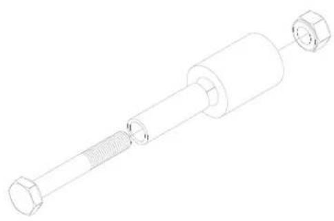
natural_image
Technical line drawing of a mechanical component with threaded shaft and flange (no text or symbols)Pawl Bar Roller Replacement Kit 06401-003-11-80
Replacement Kit Notes:
The replacement kit for the pawl bar roller comes with the roller, roller shaft, hardware and locknut as shown.
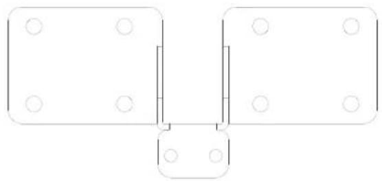
natural_image
Pure technical line drawing of a symmetrical mechanical or architectural component with circular holes, no text or symbols present.Pawl Bar Bracket (without tabs) Weldment 05700-031-92-36
natural_image
Pure technical line drawing of a symmetrical mechanical or architectural component with mounting holes (no text or symbols)Pawl Bar Bracket (with studs) Weldment 05700-031-84-68
natural_image
Simple line drawing of a U-shaped frame with mounting holes (no text or symbols)Pawl Bar Gutter Weldment Replacement Kit 06401-003-09-95
Replacement Kits Notes:
The pawl bar gutter weldment replacement kit contains the weldment, a gasket and the mounting hardware. The guide block kit contains both blocks and a gasket.
natural_image
Simple geometric diagram with a rectangle and vertical line, surrounded by four small circles (no text or symbols)Pawl Bar Gutter Gasket 05330-011-68-55

Top Guide Block
Guide Block Replacement Kit 06401-003-10-15
Bottom Guide Block
natural_image
Pure geometric diagram with nested rectangles and circles, no text or symbols presentService Note: It is highly recommended that when changing out one guide block, that the other be changed out as well, along with the gasket.
SECTION 5: PARTS SECTION
PAWL BAR ASSEMBLIES
| Model | Left to Right | Right to Left | Pawl Bar | |||
| Pawl Bar Weldment | Pawl Bar Weldment | Dogs | Complete Assembly | Prison Package | ||
AJ-64 05700-031-81-03 05700-031-81-03 18 06401-131-81-02 06401-231-81-02
AJ-86 05700-041-83-67 05700-002-81-34 24 06401-131-83-75 (L-R) 06401-331-83-75
06401-231-83-75 (R-L)
AJ-86 N/A 05700-003-13-63 24 N/A (L-R) N/A
With Side Loader 05700-003-13-64 (R-L) N/A
AJ-100 05700-041-91-13 05700-041-91-13 28 06401-141-91-05 06401-241-91-05
PAWL BAR WELDMENT
AJ-86 RIGHT TO LEFT WITH A SIDE LOADER

natural_image
Pure structural diagram of a beam with supports and load, no text or symbols presentSECTION 5: PARTS SECTION RACK RAIL ASSEMBLIES
Left to Right Assembly (AJ-86 Model shown for reference)
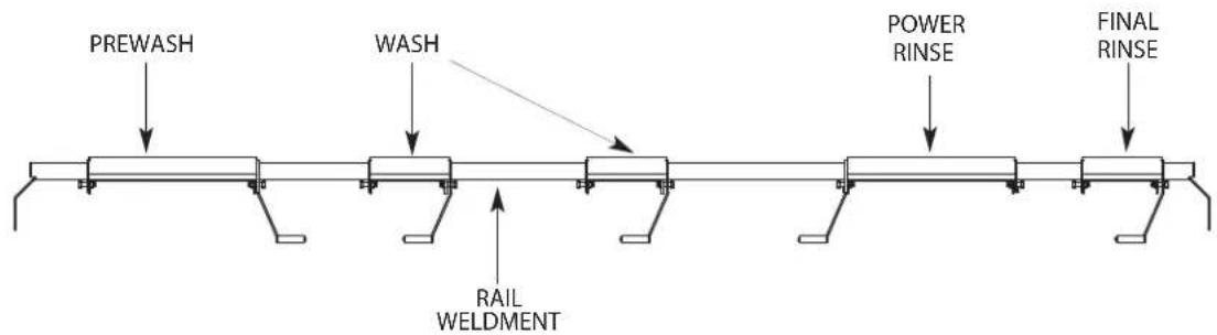
flowchart
graph LR
    A["PREWASH"] --> B["WASH"]
    B --> C["RAIL WELDMENT"]
    C --> D["POWER RINSE"]
    D --> E["FINAL RINSE"]
Right to Left Assembly (AJ-86 Model shown for reference)
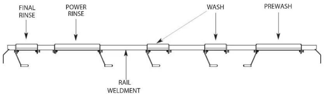
LEFT TO RIGHT:
COMPONENT AJ-64 MODELS AJ-86 MODELS AJ-100 MODELS
Prewash Actuator Not Applicable 05700-021-76-97 05700-021-75-68 Wash Actuator 05700-021-72-39 05700-021-72-39 05700-021-72-39 Power Rinse Actuator 05700-002-91-09 05700-002-91-09 05700-002-91-09 Final Rinse Actuator 05700-021-72-39 05700-021-72-39 05700-021-72-39 Rail Weldment 05700-002-74-57 05700-031-83-96 05700-041-94-91 Complete Assembly 05700-002-74-55 05700-041-83-72 05700-041-94-90
RIGHT TO LEFT:
COMPONENT AJ-64 MODELS AJ-86 MODELS AJ-100 MODELS
Prewash Actuator Not Applicable 05700-021-76-97 05700-021-76-96 Wash Actuator 05700-021-72-39 05700-021-72-39 05700-002-91-10 Power Rinse Actuator 05700-021-72-39 05700-022-91-09 05700-021-72-39 Final Rinse Actuator 05700-021-72-39 05700-021-72-39 05700-021-72-39 Rail Weldment 05700-002-74-58 05700-041-91-21 05700-041-91-03 Complete Assembly 05700-002-74-56 05700-041-91-20 05700-041-91-04
SECTION 5: PARTS SECTION
MISCELLANEOUS PARTS AND WELDMENTS
Plate, Left Water
Directional
05700-021-79-27
Plate, Right Water
Directional
05700-021-79-23

natural_image
Pure geometric lines forming a vertical and horizontal shapes without any text or symbolsRun Off Sheet Weldment 05700-021-71-39
natural_image
Pure geometric diagram with horizontal and vertical lines, no text or symbols presentSplash Shield Weldment 05700-031-85-16
Hole Direction Plate Replacement Kit
06401-003-10-00
Replacement Kit Note:
The kit for the hole direction plate comes with the plate, a new gasket and the mounting hardware.
Pipe Clamp
05700-000-35-05
Rinse Drain Plate Replacement Kit
(CGP Models Only)
06401-003-10-07
natural_image
Simple geometric diagram of a circle with four evenly spaced small circles at the center (no text or symbols)Rinse Drain Plug Replacement Kit 06401-003-10-06
natural_image
Technical line drawing of a flange with bolt holes (no text or symbols)Rinse Drain Weldment Replacement Kit 06401-003-10-05
natural_image
Simple circular diagram with four evenly spaced holes, no text or symbols presentRinse Drain Plate Gasket 05330-011-72-27
Replacement Kits Notes:
The kits for the drain weldments and drain plugs come with the weldments/parts, a new gasket and the mounting hardware.
SECTION 5: PARTS SECTION
MANIFOLDS/STRAINER SUPPORT WELDMENTS
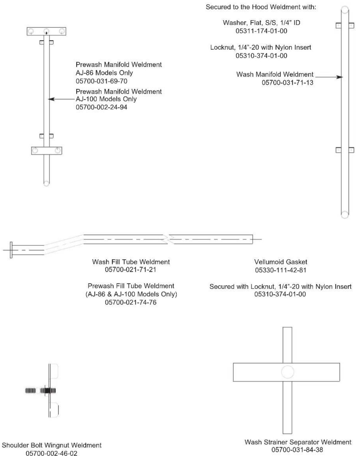
SECTION 5: PARTS SECTION
STRAINERS
natural_image
Pure geometric diagram with dashed and dotted lines, no text or symbols presentFront Strainer Weldment 05700-021-85-10
natural_image
Pure geometric diagram with dashed and solid lines forming a rectangular frame, no text or symbols presentBack Strainer Weldment 05700-021-85-11
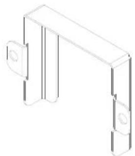
natural_image
Isometric line drawing of a mechanical bracket or support structure (no text or symbols)Overflow Strainer Support 05700-001-96-48
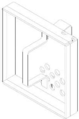
natural_image
Isometric line drawing of a rectangular enclosure with internal compartments and circular cutouts (no text or symbols)Drain Guard Strainer Weldment 05700-002-09-15
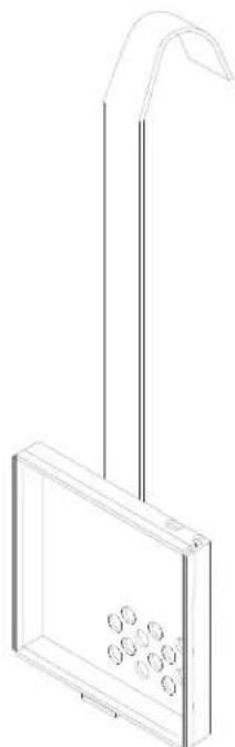
natural_image
Line drawing of a vertical support structure with circular elements inside, no text or symbols presentWash Intake Strainer Weldment (CGP Models) 05700-002-51-52
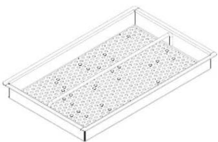
natural_image
Isometric line drawing of a rectangular container with a perforated interior and circular holes (no text or symbols)Tub Strainer Weldment (CGP Models) 05700-002-03-21
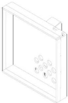
natural_image
Isometric line drawing of a rectangular enclosure with circular indentations on the front panel (no text or symbols)Screen Strainer with Handle Weldment 05700-002-09-04
SECTION 5: PARTS SECTION
FLOAT SWITCH COMPONENTS/SCRAP BASKETS
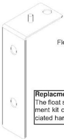
Float Switch Support Bracket Replacement Kit 06401-003-11-77
Replacement Kit Note:
The float switch support bracket replacement kit contains the bracket and associated hardware for mounting.
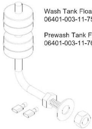
Wash Tank Float Switch Replacement Kit
06401-003-11-75
Prewash Tank Float Switch Replacement Kit 06401-003-11-76
natural_image
Simple diagram with two circles inside a rectangle, no text or symbols presentFloat Switch Cover 05700-021-75-71
Replacement Kit Note:
The float switch replacement kits contain the float switch with associated terminals, the flat washer and the nut.
Service Agent Note:
Remember than when reinstalling the float switch that the flat washer goes inside against the tub wall while the nut is on the outside of the tub.
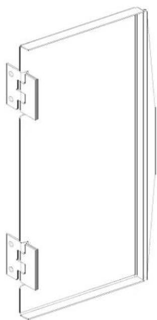
natural_image
Pure technical line drawing of a rectangular frame with two side panels and mounting holes (no text or symbols)Scrap Basket Lid Weldment 05700-002-56-55
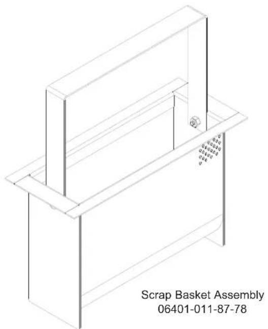
natural_image
Isometric line drawing of a Scrap Basket Assembly (no text or symbols on the diagram itself)SECTION 5: PARTS SECTION
CURTAINS/TUB MAGNETS
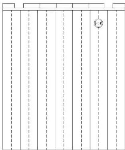
natural_image
Pure architectural floor plan lines without any text, numbers, or symbolsCurtain, 24 1/2" Long x 20-1/2" Wide CGP MODELS ONLY 08415-002-47-37
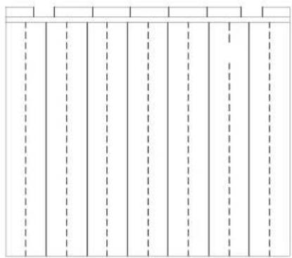
natural_image
Pure geometric lines with dashed vertical and horizontal segments, no text or symbols presentCurtain, 21" Long x 20-1/2" Wide 08415-131-73-45
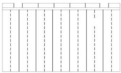
natural_image
Pure geometric pattern of vertical dashed lines and rectangles without any text, numbers, or symbolsCurtain, 12" Long x 20-1/2" Wide 08415-131-73-44

Long Curtain Decal
09905-011-73-84

Short Curtain Decal
09905-011-73-82

Extra Long Curtain Decal
CGP MODELS ONLY
09905-002-52-69

Curtain Hook
05700-011-83-54
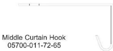
Curtain Rod 05700-021-73-43
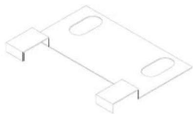
natural_image
Isometric line drawing of a rectangular metal bracket with two side notches (no text or symbols)Limit Switch Bracket 05700-021-71-18
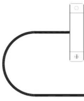
natural_image
Pure electrical circuit lines without any symbolsConveyor Switch Replacement Kit
06401-003-11-79
Replacement Kit Note:
The conveyor switch replacement kit comes with the switch, a terminal and a wire nut.
Service Note:
The cord for the conveyor switch needs to be cut to length in the field and have the pink terminal applied there.
SECTION 5: PARTS SECTION
VENT COWL ASSEMBLY/VENT SCOOP OPTION
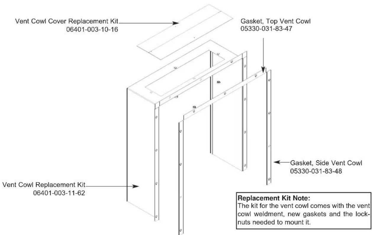
VENT SCOOP OPTION
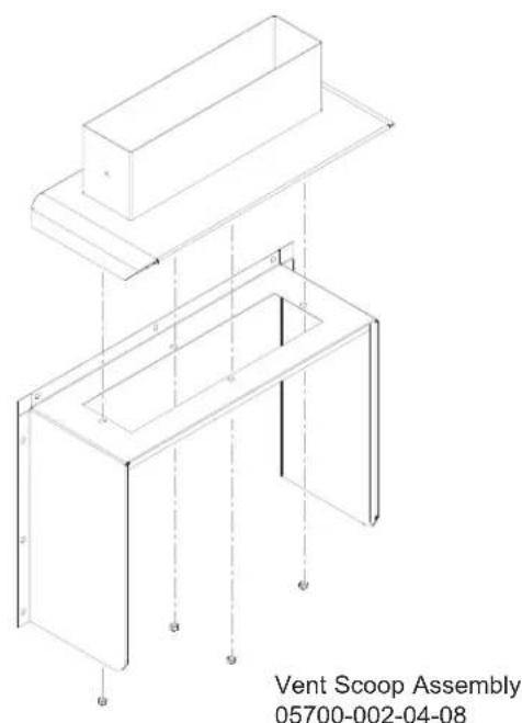
SECTION 5: PARTS SECTION
EXHAUST FAN CONTROL/TABLE LIMIT SWITCH OPTIONS
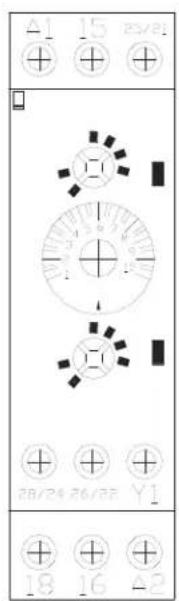
Delay Timer 05945-011-65-44
natural_image
Simple diagram with two empty rounded rectangles on a horizontal line (no text or symbols)2" Din Rail 05700-002-36-09
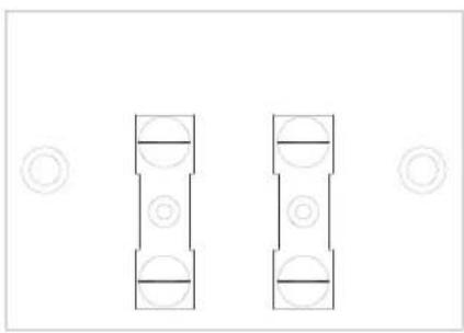
natural_image
Pure diagram of two vertical cylindrical shapes with circular cutouts, no text or symbols presentTerminal Board 05940-011-84-41
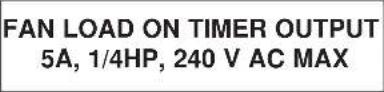
Decal, Fan Load
09905-003-32-20
Kit, Exhaust Fan - Electric & Steam Models
05700-031-90-53
Kit, Exhaust Fan - Gas Models
05700-003-14-59
Limit Switch
05930-002-62-81
Striker Plate Limit Switch
Assembly
05700-002-62-94
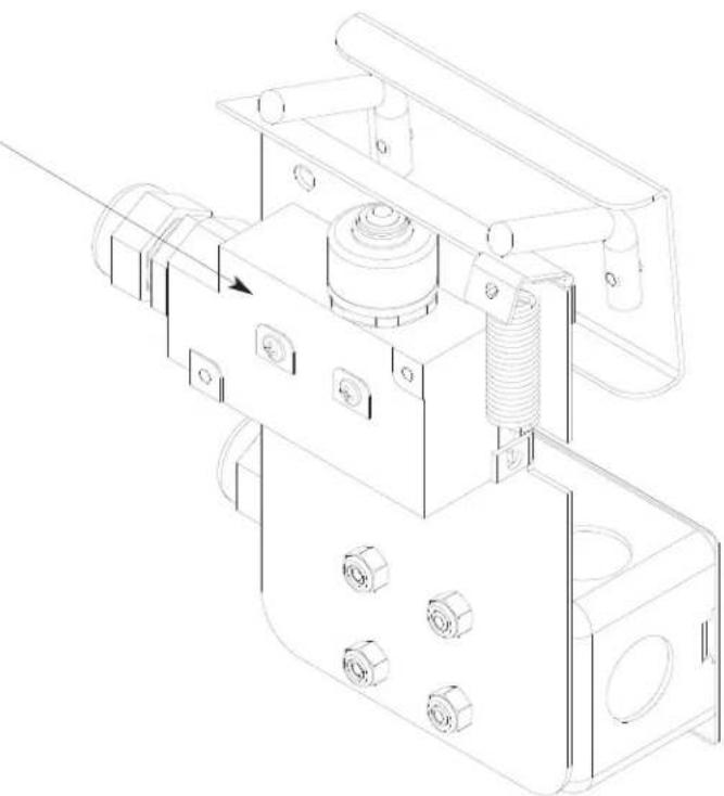
natural_image
Technical line drawing of a mechanical assembly with bolts and a spring (no text or symbols)SECTION 5: PARTS SECTION
SIDE LOADER TRACK ASSEMBLY/LEG REPLACEMENTS/STRAINER
Side loader track assembly (left to right model shown).
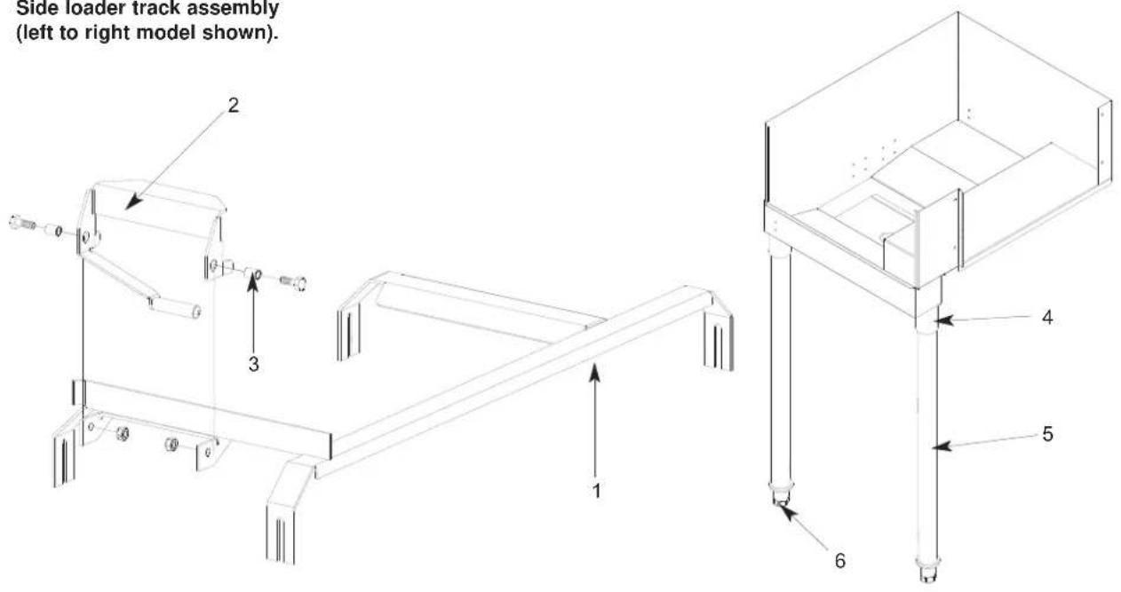
ITEM QTY DESCRIPTION Mfg. No.
1 1 Track Weldment (Left to Right) 24" 05700-031-78-98
1 Track Weldment (Right to Left) 24" 05700-031-95-20
1 Track Weldment (Left to Right) 30" 05700-003-04-57
1 Track Weldment (Right to Left) 30" 05700-003-04-58
2 1 Actuator Switch Replacement Kit 06401-003-10-64
3 2 S p a c e
4 1 Leg Socket Replacement Kit 06401-003-09-79
5 1 Leg Support Replacement Kit 06401-003-09-80
6 1 Bullet Foot 05340-108-01-03
Replacement Kits Notes:
The actuator switch replacement kit comes with the actuator weldment, mounting hardware and (2) spacers.
The leg socket replacement kit has the leg socket, mounting hardware and set screw.
The leg support replacement kit has the leg and the bullet foot included.
05700-011-71-44
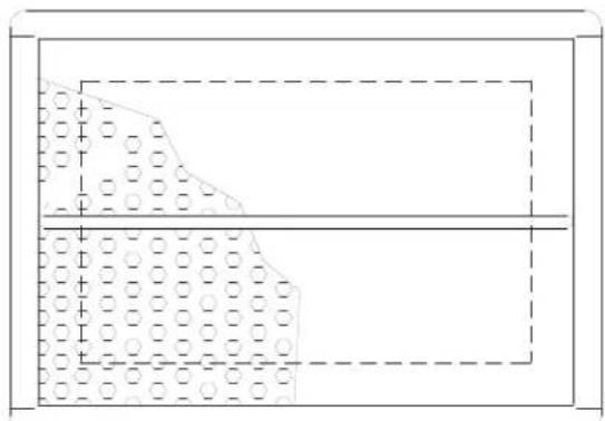
natural_image
Pure technical diagram showing a rectangular structure with internal dotted patterns and dashed lines, no text or symbols present.Front Strainer Weldment 05700-021-85-10
SECTION 5: PARTS SECTION
SIDE LOADER PAWL BAR ASSEMBLIES/PAWL BAR BRACKET/MAGNET
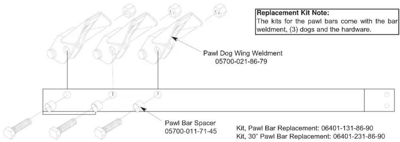
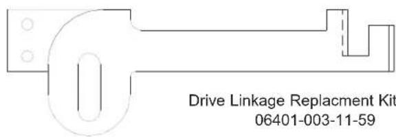
Replacement Kit Note:
The replacement kits for the drive linkages come also with the hardware for mounting them to the pawl bars.

natural_image
Pure mechanical part outline diagram without any text, numbers, or symbolsDrive Linkage Replacement (R-L) 06401-003-11-60
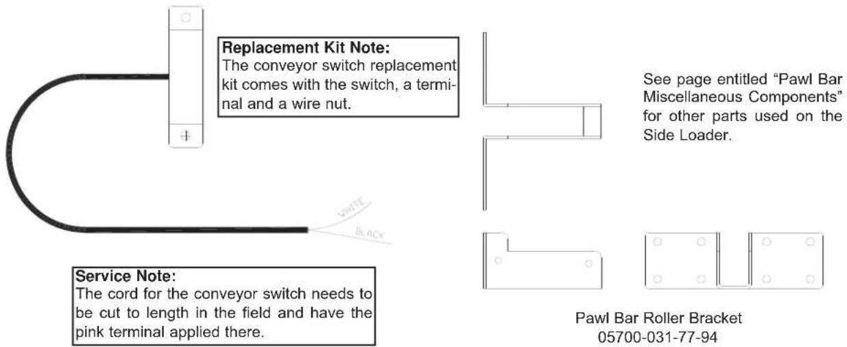
SECTION 5: PARTS SECTION
SIDE LOADER VENT COWL OPTION
Service Note:
One of the side gaskets that come in the kit will need to be cut to length in order to fit properly on the unit when replaced.
Vent Cowl Replacement Kit (Left to Right)
06401-003-11-81
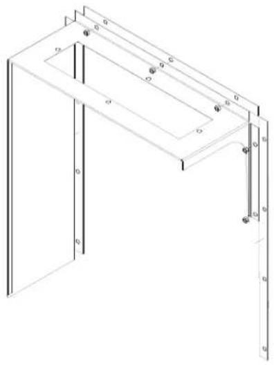
natural_image
Isometric line drawing of a rectangular frame with internal compartments and mounting feet (no text or symbols)Vent Cowl Replacement Kit (Right to Left)
06401-003-11-83
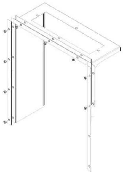
natural_image
Isometric line drawing of a rectangular frame with vertical supports and mounting holes (no text or symbols)Replacement Kit Note:
The replacement kit(s) for the vent cowls come with the cowls, the gaskets and mounting hardware.
Vent Cowl Gasket, Top: 05330-031-83-47
Vent Cowl Gasket, Side: 05330-031-83-48
VENT SCOOP OPTION
Vent Scoop Assembly 05700-002-04-08
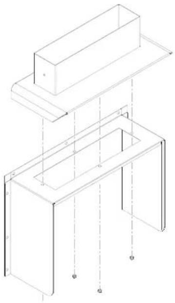
natural_image
Isometric line drawing of a two-tiered structural frame with mounting holes and dashed lines indicating hidden edges (no text or symbols)STANDARD ASSEMBLY
Vent Cowl Cover Replacement Kit 06401-003-10-16
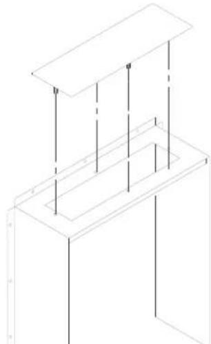
natural_image
Isometric line drawing of a 3D rectangular structure with vertical and horizontal lines, no text or symbols presentVent Cowl Assembly for
Hooded Side Loader Option 05700-003-15-66
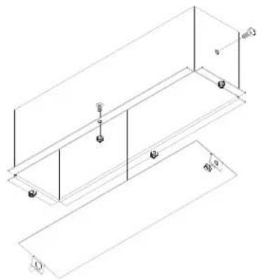
natural_image
Isometric technical drawing of a rectangular enclosure with internal supports and mounting points (no text or symbols)Replacement Kit Note:
The cover kit contains the cover and the hardware for mounting it.
SECTION 5: PARTS SECTION
D226 STEAM BOOSTER CONTROL BOX ASSEMBLY
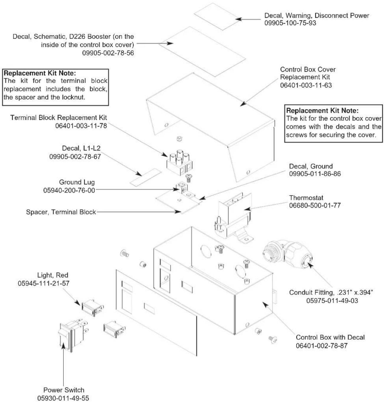
SECTION 5: PARTS SECTION
D226 STEAM BOOSTER PLUMBING ASSEMBLY
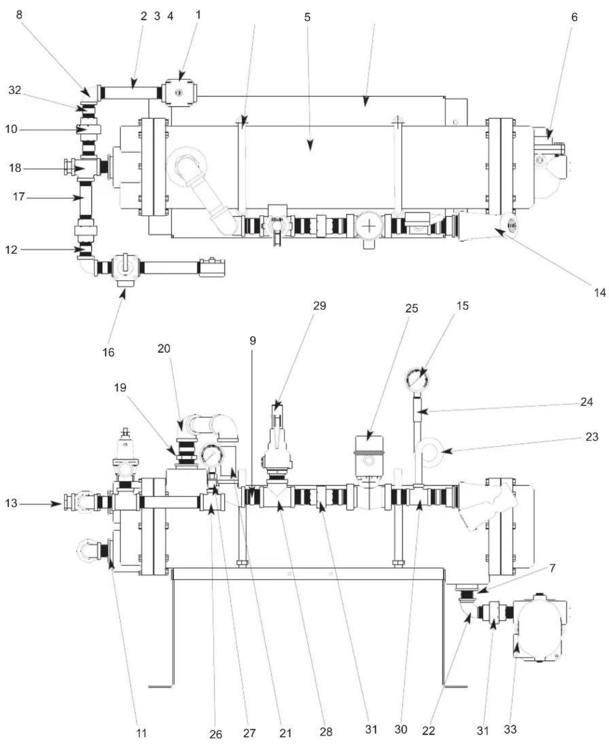
SECTION 5: PARTS SECTION
D226 STEAM BOOSTER PLUMBING ASSEMBLY (CONTINUED)
ITEM QTY DESCRIPTION Mfg. No.
1 1 Water Pressure Regulator, 3/4" 04820-100-01-06
2 2 Nipple, Brass, 3/4" NPT x 6" Long 05700-001-26-74
3 2 U-Bolt, 6", 5/8"-11 Thread 05306-458-01-04
4 1 Platform Weldment 05700-002-78-02
5 1 Heat Exchanger 04420-100-01-05
6 1 Steam Trap, 3/4" 06680-500-02-77
7 1 Bushing, 2" NPT x 3/4" NPT, Black Iron 04730-902-06-34
8 2 Elbow, 3/4" NPT, Brass 04730-206-13-00
9 6 Nipple, 1" NPT, Close, Black Iron 04730-907-08-34
10 2 Union, 3/4" NPT, Brass
11 2 Bushing, 2" NPT x 3/4" NPT, Brass
12 4 Nipple, 3/4" NPT x 1-3/8" Long
13 1 Bushing, Hex 3/4" M x 1/2" F, Brass
14 1 Y-Strainer, 1" NPT, Black Iron
15 2 Pressure Gauge
16 1 Steam Relief Valve
17 2 Nipple, 3/4" NPT x 4" Long, Brass 04730-207-05-00
18 2 Tee, 3/4" NPT x 3/4" NPT x 3/4" NPT, Brass
19 1 Bushing, 2" NPT x 1" NPT, Black Iron
20 3 Elbow, 90°, 1" NPT, Black Iron
21 2 Nipple, 1" NPT x 4" Long, Black Iron
22 1 Elbow, 90°, Street, 3/4" NPT, Black Iron
23 1 Nipple, Pigtail, 1/4" NPT
24 1 Coupling, 1/4" NPT x 1/4" NPT
25 1 Steam Solenoid Valve, 240VA
25 1 Steam Solenoid Valve, 200VA
25 1 Steam Solenoid Valve (ASCO)
26 1 Tee, 3/4" NPT x 3/4" NPT x 1/4" NPT, Brass
27 1 Valve, Test Cock, 1/4" NPT
28 1 Tee, 1" NPT x 1" NPT x 1" NPT, Black Iron
29 1 Valve, Safety Relief 1" NPT
30 1 Tee, 1" NPT x 1" NPT x 1/4" NPT, Black Iron
31 2 Union, 3/4" NPT, Black Iron
32 2 Nipple, 3/4" NPT x 2" Long, Brass 04730-207-46-00
33 2 Nipple, 3/4" NPT, Close, Black Iron
04730-212-05-00
04730-202-18-00
04730-207-34-00
04730-002-56-27
04730-217-02-32
06685-111-88-34
04820-100-07-06
04730-211-01-34
04730-002-94-51
04730-906-03-34
04730-907-09-34
04730-011-87-37
04730-907-14-34
04730-904-01-34
04820-100-29-34
04820-002-93-66
04820-002-90-26
04730-211-04-00
04810-011-72-67
04730-911-01-34
04820-100-01-35
04730-911-01-00
04730-912-01-00
04730-907-01-00
SECTION 5: PARTS SECTION
GO\*BOX COMPONENTS
A GO*BOX is a kit of the most needed parts for a particular model or model family to successfully effect a repair in the first call 90% or more of the time.
The following components may be ordered together using part number 06401-002-14-99.
QTY DESCRIPTION Mfg. No.
1 Drive Motor Contactor 05945-111-68-38
1 Contactor, Wash Heater, 3 ph, 3 pole 05945-002-24-70
1 Contactor, Wash Heater, 1 ph, 4 pole 05945-111-68-37
2 Final Rinse Arm End Cap 05700-011-35-92
1 Float Switch, Dual, Wash & Prewash 06680-121-70-71
1 Gasket, Pawl Bar Gutter 05330-011-68-55
1 Gauge, Pressure 06685-111-88-34
6 Glide, Door Edge 05700-111-70-92
2 Magnet, Door Reed Switch 05930-111-51-68
1 Overload, Drive Motor 05945-111-68-39
2 Switch, Power 05930-011-49-55
2 O Ring, Prewash Manifold 05330-400-12-08
2 O Ring, Wash Manifold 05330-011-74-56
1 Overload, Wash Motor 05945-111-68-40
1 Relay,120v, 3 PDT 05945-111-72-51
1 Relay,120v,50/60Hz 3A Control 05945-111-35-19
1 Repair Kit, 3/4" Vacuum Breaker 04820-001-60-57
4 Roller, Pawl Bar 05700-011-68-16
1 Seal Kit for Wash and Prewash pump 05330-011-71-98
2 Solenoid Valve, Fill & Rinse 04810-100-53-00
2 Switch, Reed, Actuator (NC) 05930-111-68-44
1 Switch, Reed, Door (NO) 05930-111-68-86
1 Thermometer, 48" Capillary 06685-111-68-48
1 Thermometer, 96" Capillary 06685-111-68-49
2 Thermostat, Wash High Limit 05930-121-71-36
2 Thermostat, Wash Regulating 05930-121-67-72
1 Transformer,150VA 05950-011-68-35
1 Valve, Ball 1 1/2" NPT 04820-111-71-46
SECTION 5: PARTS SECTION
RINSE FILL MOTOR OPTION
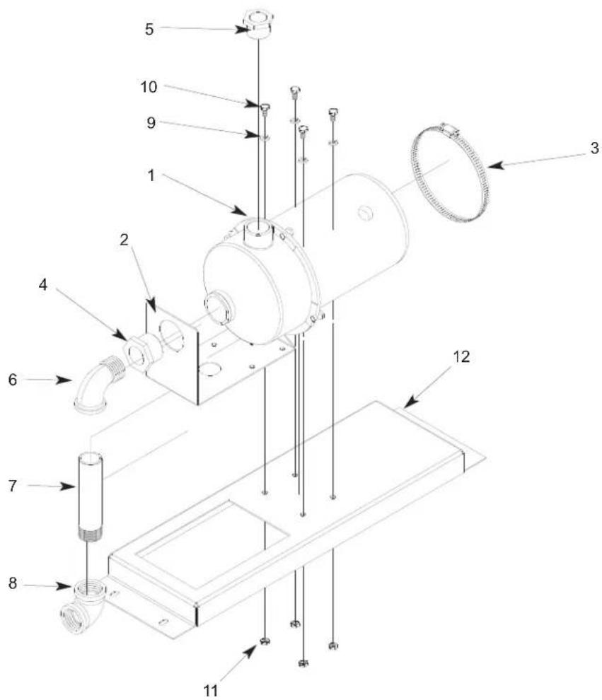
ITEM QTY DESCRIPTION Mfg. No.
1 Rinse Fill Motor Assembly 05700-002-40-25
1 1 Motor 06105-002-72-71
2 1 Bracket, Pump Mounting 05700-002-63-59
3 1 Clamp, Hose 5 5/8" to 6" 04730-011-34-90
4 1 Reducer Bushing, 1 1/4" to 1" 04730-002-73-62
5 1 Reducer Bushing 1" to 3/4" 04730-011-65-14
6 1 Elbow, 90 Deg., 1" Street 04730-002-11-99
7 1 Nipple, 1" NPT x 6" Long Brass 04730-002-12-00
8 1 Elbow, 90 Deg. Brass Female 04730-002-12-55
9 4 Lockwasher, 1/4"
10 4 Bolt, 1/4"-20 x 1/2" Long
11 4 Nut, Hex S/S 1/4"-20
12 1 Rinse Motor Mounting Bracket
05311-274-01-00
05305-274-02-00
05310-274-01-00
05700-002-38-90
SECTION 6: ELECTRICAL SCHEMATICS
SECTION 6: ELECTRICAL SCHEMATICS
AJ-64CE (208-230 VOLT, 60 HZ, SINGLE PHASE) PRIMARY SIDE
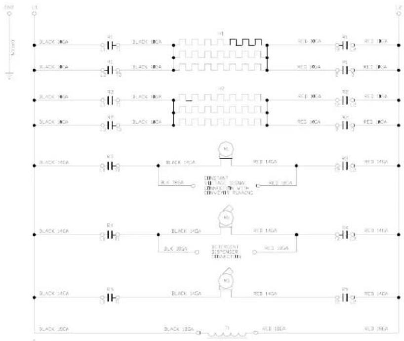
SECTION 6: ELECTRICAL SCHEMATICS
AJ-64CE (208-230 VOLT, 60 HZ, SINGLE PHASE) SECONDARY SIDE
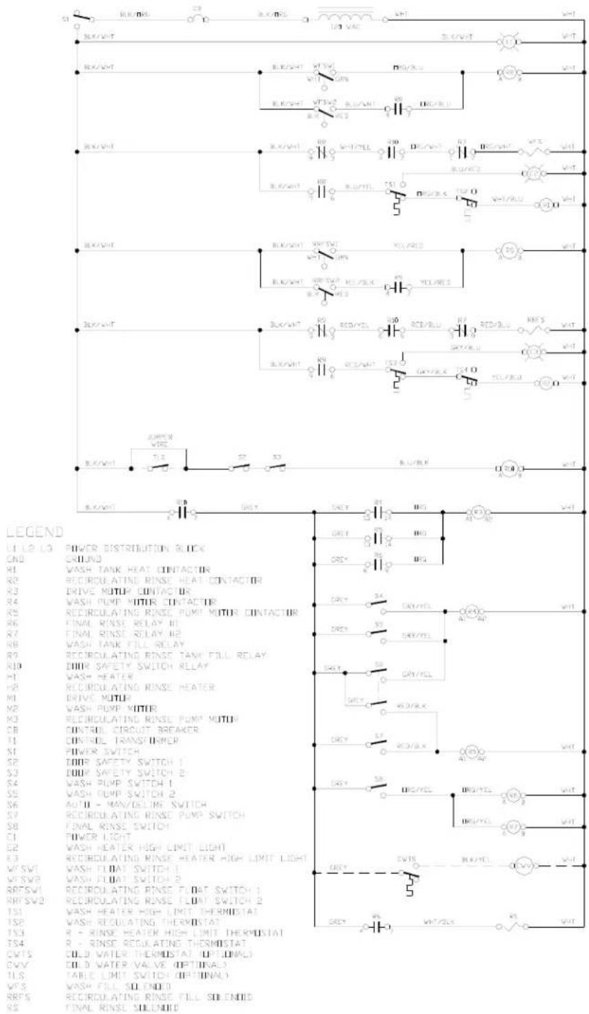
SECTION 6: ELECTRICAL SCHEMATICS
AJ-64CE (208-230 VOLT, 60 HZ, THREE PHASE) PRIMARY SIDE
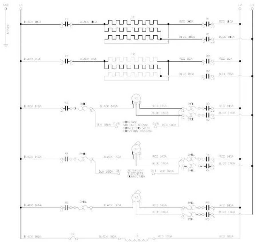
SECTION 6: ELECTRICAL SCHEMATICS
AJ-64CE (208-230 VOLT, 60 HZ, THREE PHASE) SECONDARY SIDE
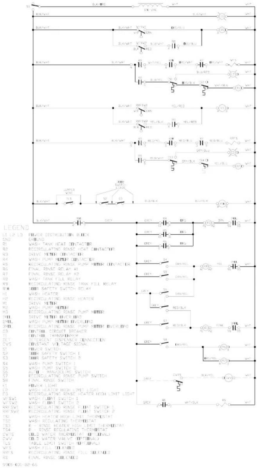
SECTION 6: ELECTRICAL SCHEMATICS
AJ-64CE (460 VOLT, 60 HZ, THREE PHASE) PRIMARY SIDE
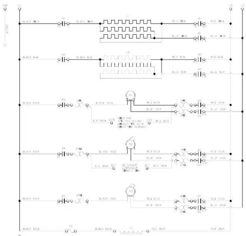
SECTION 6: ELECTRICAL SCHEMATICS
AJ-64CE (460 VOLT, 60 HZ, THREE PHASE) SECONDARY SIDE
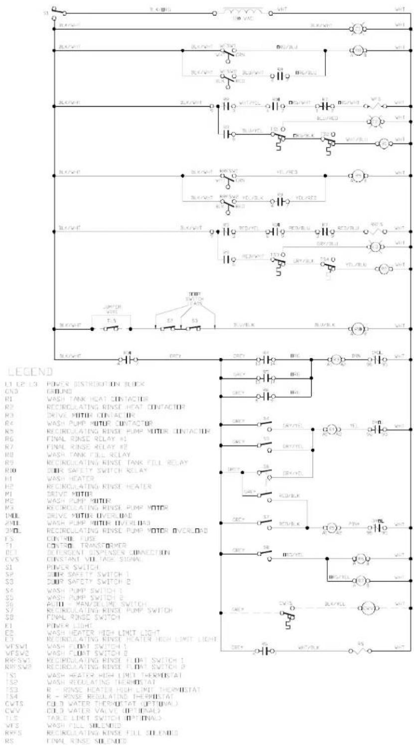
09905-031-95-56
SECTION 6: ELECTRICAL SCHEMATICS
AJ-64CS (208-230 VOLT, 60 HZ, SINGLE PHASE) PRIMARY SIDE
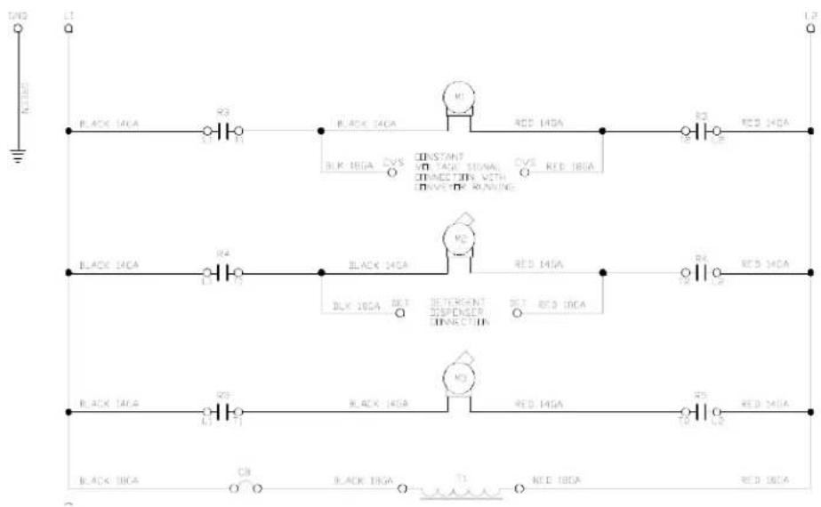
SECTION 6: ELECTRICAL SCHEMATICS
AJ-64CS (208-230 VOLT, 60 HZ, SINGLE PHASE) SECONDARY SIDE
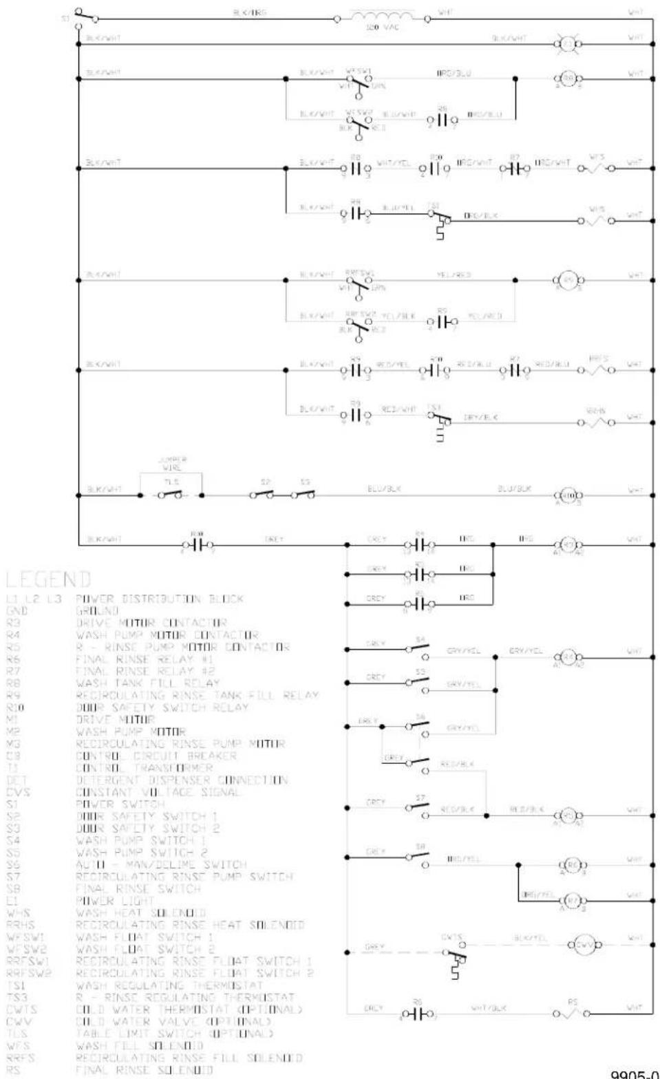
9905-002-55-96a
SECTION 6: ELECTRICAL SCHEMATICS
AJ-64CS (208-230 VOLT, 60 HZ, THREE PHASE) PRIMARY SIDE
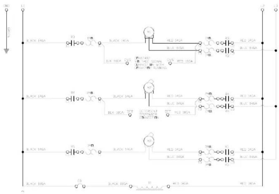
SECTION 6: ELECTRICAL SCHEMATICS
AJ-64CS (208-230 VOLT, 60 HZ, THREE PHASE) SECONDARY SIDE
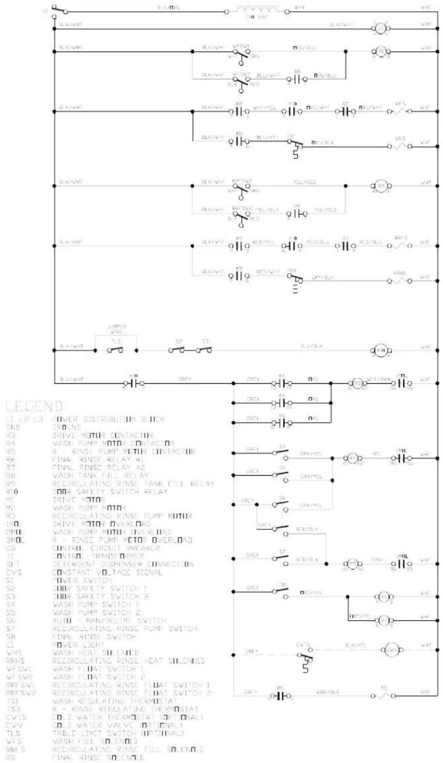
9905-002-17-056
SECTION 6: ELECTRICAL SCHEMATICS
AJ-64CS (460 VOLT, 60 HZ, THREE PHASE) PRIMARY SIDE
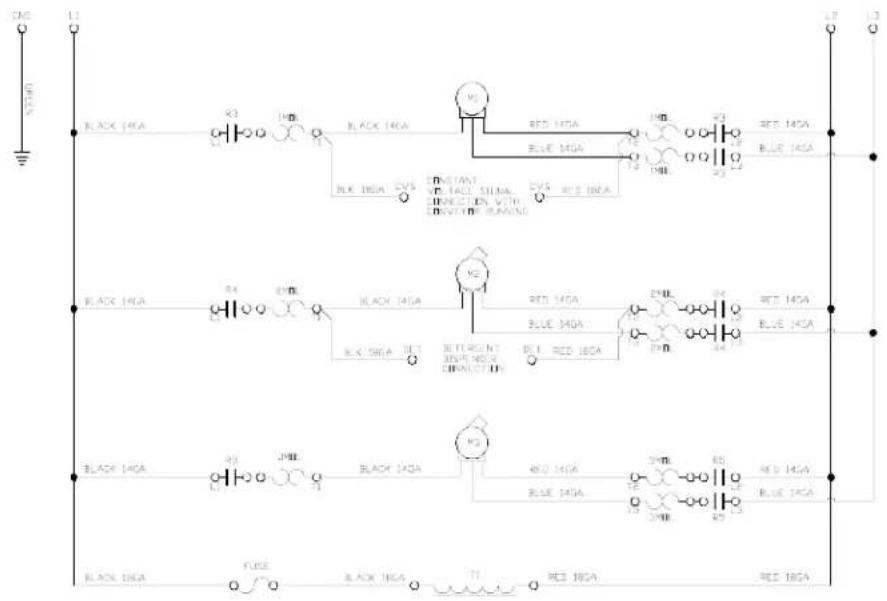
SECTION 6: ELECTRICAL SCHEMATICS
AJ-64CS (460 VOLT, 60 HZ, THREE PHASE) SECONDARY SIDE
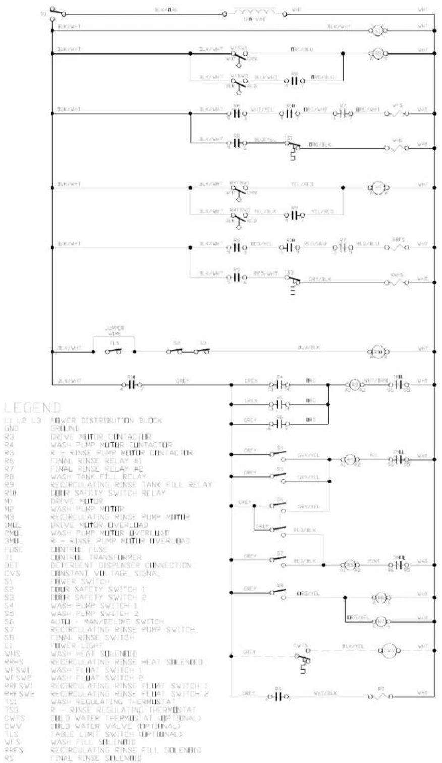
9905-002-53-97a
SECTION 6: ELECTRICAL SCHEMATICS
AJ-86CE & AJ-100CE (208-230 VOLT, 60 HZ, SINGLE PHASE) PRIMARY SIDE
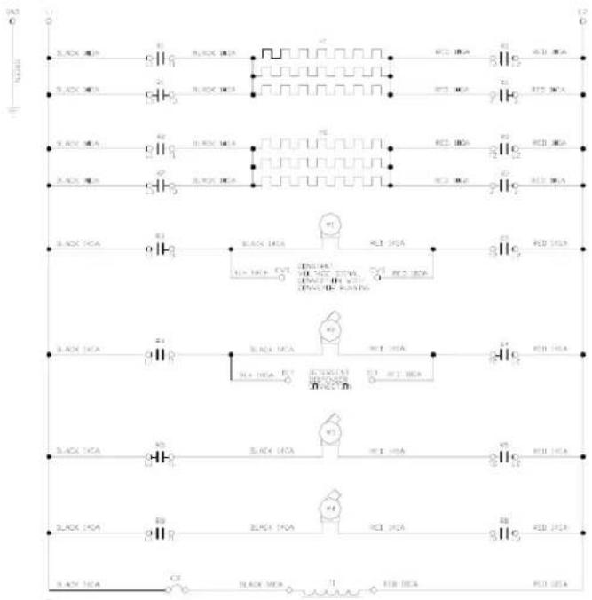
SECTION 6: ELECTRICAL SCHEMATICS
AJ-86CE & AJ-100CE (208-230 VOLT, 60 HZ, SINGLE PHASE) SECONDARY SIDE
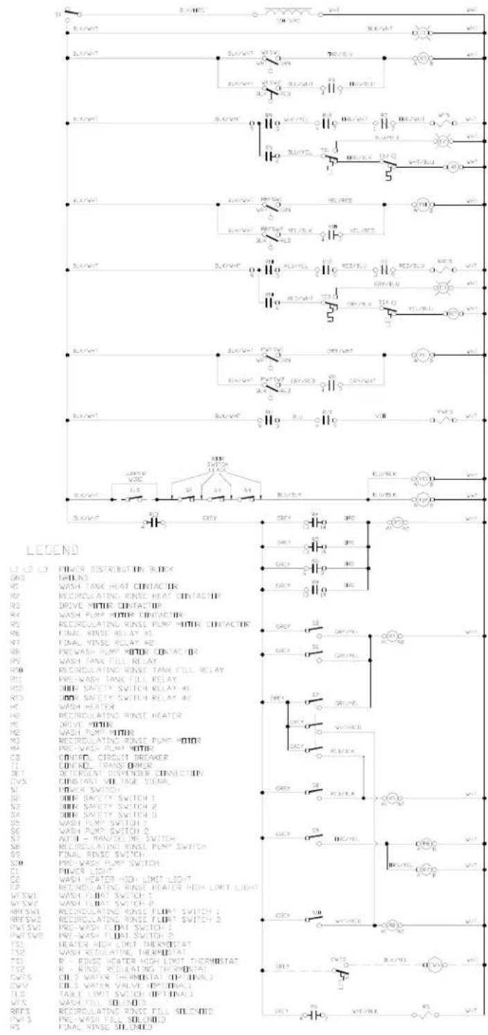
09905-031-80-35
SECTION 6: ELECTRICAL SCHEMATICS
AJ-86CE & AJ-100CE (208-230 VOLT, 60 HZ, THREE PHASE) PRIMARY SIDE
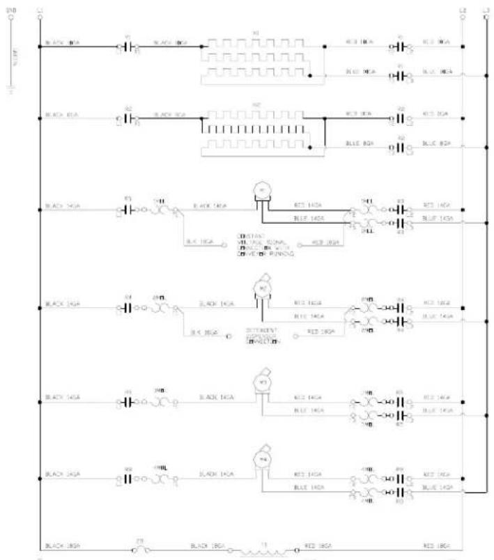
flowchart
graph TD
    A["Black ICA"] --> B["BLT"]
    B --> C["Blue ICA"]
    C --> D["Red ICA"]
    D --> E["Black ICA"]
    E --> F["BLT"]
    F --> G["Blue ICA"]
    G --> H["Red ICA"]
    H --> I["Black ICA"]
    I --> J["BLT"]
    J --> K["Blue ICA"]
    K --> L["Red ICA"]
    L --> M["Black ICA"]
    M --> N["BLT"]
    N --> O["Blue ICA"]
    O --> P["Red ICA"]
    P --> Q["Black ICA"]
    Q --> R["BLT"]
    R --> S["Blue ICA"]
    S --> T["Red ICA"]
    T --> U["Black ICA"]
    U --> V["BLT"]
    V --> W["Blue ICA"]
    W --> X["Red ICA"]
    X --> Y["Black ICA"]
    Y --> Z["BLT"]
    Z --> AA["Blue ICA"]
    AA --> AB["Red ICA"]
SECTION 6: ELECTRICAL SCHEMATICS
AJ-86CE & AJ-100CE (208-230 VOLT, 60 HZ, THREE PHASE) SECONDARY SIDE
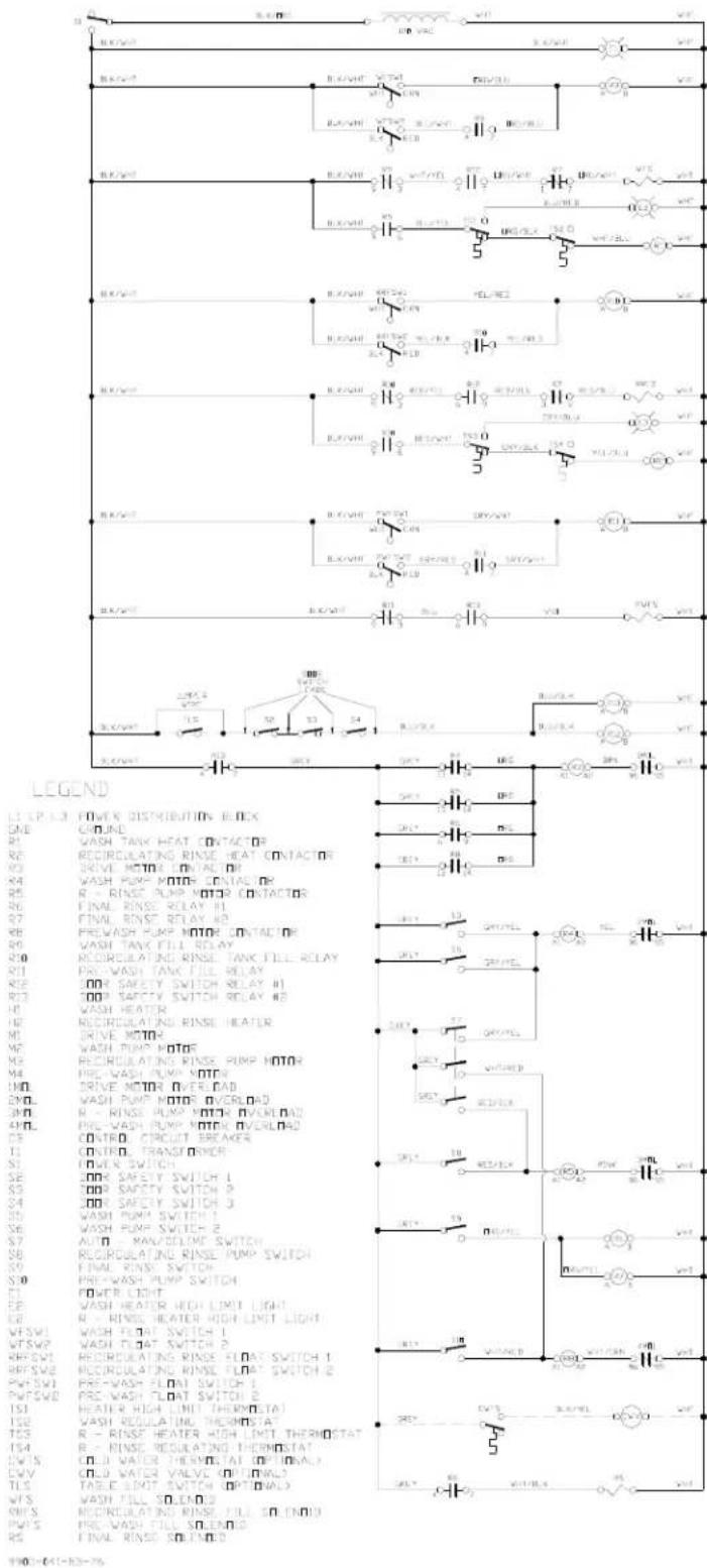
SECTION 6: ELECTRICAL SCHEMATICS
AJ-86CE & AJ-100CE (460 VOLT, 60 HZ, THREE PHASE) PRIMARY SIDE
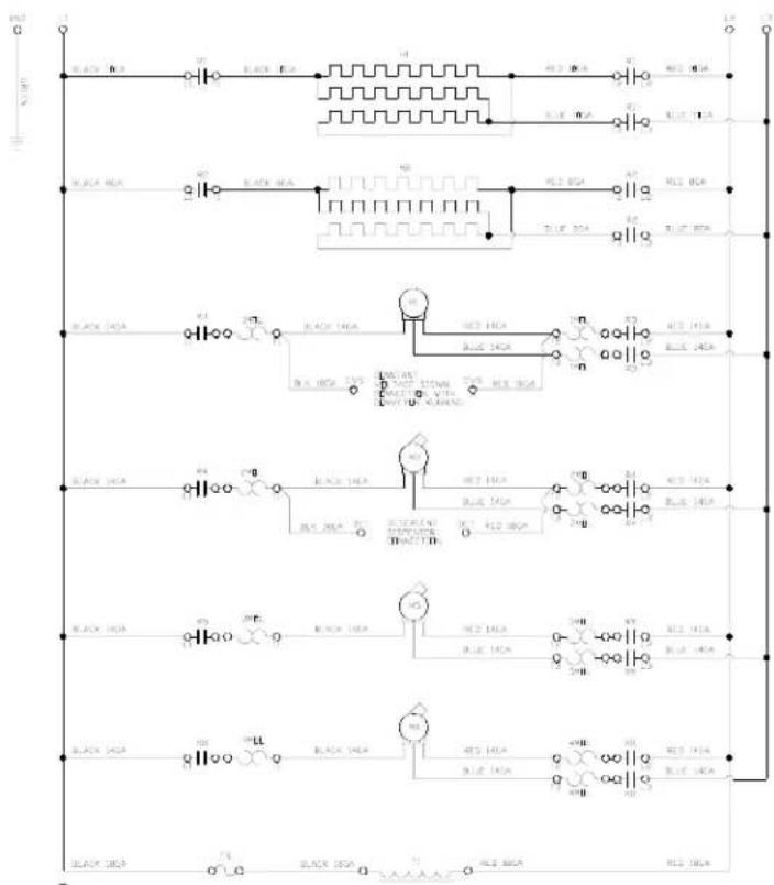
SECTION 6: ELECTRICAL SCHEMATICS
AJ-86CE & AJ-100CE (460 VOLT, 60 HZ, THREE PHASE) SECONDARY SIDE
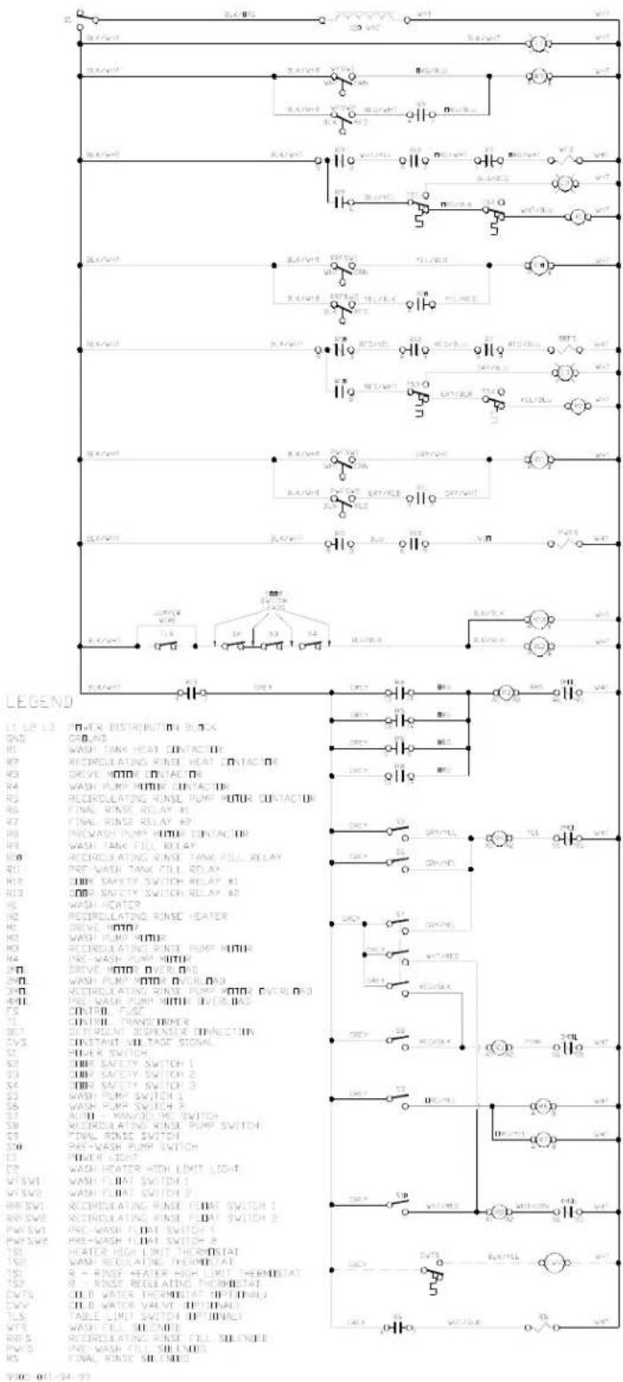
flowchart
graph TD
    A["Power Distribution Block"] --> B["Ground"]
    B --> C["Wash Tank Heat Contact IR"]
    C --> D["Recrepulating Rinse Heat Contact IR"]
    D --> E["Drive MTRI Contact IR"]
    E --> F["Wash Pump MTRI Contact IR"]
    F --> G["Recrepulating Rinse Pump Motor Contact IR"]
    G --> H["Final Rinse Relay IR"]
    H --> I["Final Rinse Relay AP"]
    I --> J["PreWash Pump MTRI Contact IR"]
    J --> K["Wash Tank Fill RELAY"]
    K --> L["Recrepulating Rinse Tank Fill RELAY"]
    L --> M["Pre Wash Tank Fill RELAY"]
    M --> N["DRK Safety Switch RELAY IR"]
    N --> O["DRR Safety Switch RELAY AP"]
    O --> P["Wash Heater"]
    P --> Q["Recrepulating Rinse Heater"]
    Q --> R["Drive MTRI"]
    R --> S["Wash Pump Motor"]
    S --> T["Recrepulating Rinse Pump Motor Overload IR"]
    T --> U["Pre-Wash Pump Motor Overload IR"]
    U --> V["CONTROL SWITCH"]
    V --> W["DRR Safety Switch 1"]
    W --> X["DRR Safety Switch 2"]
    X --> Y["DRR Safety Switch 3"]
    Y --> Z["Wash Pump Switch 1"]
    Z --> AA["Wash Pump Switch 2"]
    AA --> AB["AUDI - Manual ON Switch"]
    AB --> AC["Recrepulating Rinse Pump Switch"]
    AC --> AD["Final Rinse Switch"]
    AD --> AE["PWR-WASH Pump Switch"]
    AE --> AF["Power Light"]
    AF --> AG["Wash Heater High Limit Light"]

    subgraph Legend
        direction TB
        direction LR
        direction CV
        direction CS
        direction DV
        direction DV
        direction DV
        direction DV
        direction DV
        direction DV
        direction DV
        direction DV
        direction DV
        direction DV
        direction DV
        direction DV
        direction DV
        direction DV
        direction DV
        direction DV
        direction DV
        direction DV
        direction DV
        direction DV
        direction DV
        direction DV
        direction DV
        direction DV
        direction DV
        direction GV
        direction GV
        direction GV
        direction GV
        direction GV
        direction GV
        direction GV
        direction GV
        direction GV
        direction GV
        direction GV
        direction GV
        direction GV
        direction GV
        direction GV
        direction GV
        direction GV
        direction GV
        direction GV
        direction GV
        direction GV
        direction GV
        direction GV
        direction GV
        direction GV
        direction SV
        direction SV
        direction SV
        direction SV
        direction SV
        direction SV
        direction SV
        direction SV
        direction SV
        direction SV
        direction SV
        direction SV
        direction SV
        direction SV
        direction SV
        direction SV
        direction SV
        direction SV
        direction SV
        direction SV
        direction SV
        direction SV
        direction SV
        direction SV
        direction SV
        direction SGV
        direction SGV
        direction SGV
        direction SGV
        direction SGV
        direction SGV
        direction SGV
        direction SGV
        direction SGV
        direction SGV
        direction SGV
        direction SGV
        direction SGV
        direction SGV
        direction SGV
        direction SGV
        direction SGV
        direction SGV
        direction SGV
        direction SGV
        direction SGVVGNDGNDGNDGNDGNDGNDGNDGNDGNDGNDGNDGNDGNDGNDGNDGNDGNDGNDGNDGNDGNDGNDGNDGNDGNDGNDGNDGNDGNDGNDGNDGNDGNDGNDGNDGNDGNDGNDGNDGNDGNDGNDGNDGNDGNDGNDGNDGNDGNDGNDGNGDNGDNGDNGDNGDNGDNGDNGDNGDNGDNGDNGDNGDNGDNGDNGDNGDNGDNGDNGDNGDNGDNGDNGDNGDNGDNGDNGDNGDNGDNGDNGDNGDNGDNGDNGDNGDNGDNGDNGDNGDNGDNGDNGDNGDNGDNGDNGDNGDNGDNGDGNDNGLMGLMGLMGLMGLMGLMGLMGLMGLMGLMGLMGLMGLMGLMGLMGLMGLMGLMGLMGLMGLMGLMGLMGLMGLMGLMGLMGLMGLMGLMGLMGLMGLMGLMGLMGLMGLMGLMGLMGLMGLMGLMGLMGLMGLMGLMGLMGLMGLMGLMGLMGNDNGLMGLMGLMGLMGLMGLMGLMGLMGLMGLMGLMGLMGLMGLMGLMGLMGLMGLMGLMGLMGLMGLMGLMGLMGLMGLMGLMGLMGLMGLMGLMGLMGLMGLMGLMGLMGLMGLMGLMGLMGLMGLMGLMGLMGLMGLMGLMGLMMLNHLNHLNHLNHLNHLNHLNHLNHLNHLNHLNHLNHLNHLNHLNHLNHLNHLNHLNHLNHLNHLNHLNHLNHLNHLNHLNHLNHLNHLNHLNHLNHLNHLNHLNHLNHLNHLNHLNHLNHLNHLNHLNHLNHLNHLNHLNHLNHLNHLNHLNRLNHLNHLNHLNHLNHLNHLNHLNHLNHLNHLNHLNHLNHLNHLNHLNHLNHLNHLNHLNHLNHLNHLNHLNHLNHLNHLNHLNHLNHLNHLNHLNHLNHLNHLNHLNHLNHLNHLNHLNHLNHLNHLNHLNHLNHLNHLNHLNHLNHLNBLAAGLNAAGLNAAGLNAAGLNAAGLNAAGLNAAGLNAAGLNAAGLNAAGLNAAGLNAAGLNAAGLNAAGLNAAGLNAAGLNAAGLNAAGLNAAGLNAAGLNAAGLNAAGLNAAGLNAAGLNAAGLNAAGLNAAGLNAAGLNAAGLNAAGLNAAGLNAAGLNAAGLNAAGLNAUGAAGLNAAGLNAAGLNAAGLNAAGLNAAGLNAAGLNAAGLNAAGLNAAGLNAAGLNAAGLNAAGLNAAGLNAAGLNAAGLNAAGLNAAGLNAAGLNAAGLNAAGLNAAGLNAAGLNAAGLNAAGLNAAGLNAAGLNAAGLNAAGLNAAGLNAAGLNAAGLNAAGLMAAGLMAAGLMAAGLMAAGLMAAGLMAAGLMAAGLMAAGLMAAGLMAAGLMAAGLMAAGLMAAGLMAAGLMAAGLMAAGLMAAGLMAAGLMAAGLMAAGLMAAGLMAAGLMAAGLMAAGLMAAGLMAAGLMAAGLMAAGLMAAGLMAAGLMAAGLMAAGLMAAGLMAUGAUGAUGAUGAUGAUGAUGAUGAUGAUGAUGAUGAUGAUGAUGAUGAUGAUGAUGAUGAUGAUGAUGAUGAUGAUGAUGAUGAUGAUGAUGAUGAUGAUGAUGAUGAUGAUGAUGAUGAUGAUGAUGAUGAUGAUGAUGAUGAUGAUGAUGAAUUAUAUAUAUAUAUAUAUAUAUAUAUAUAUAUAUAUAUAUAUAUAUAUAUAUAUAUAUAUAUAUAUAUAUAUAUAUAUAUAUAUAUAUAUAUAUAUAUAUAUAUAUAUAUAUAUAUAUAUAUAUAUAUAUAUAUAUAUAUAUAUAUAUAUAUAUAUAUAUAUAUAUAUAUAUAUAUAUAUAUAUAUAUAUAUAUAAUAAUAAUAAUAAUAAUAAUAAUAAUAAUAAUAAUAAUAAUAAUAAUAAUAAUAAUAAUAAUAAUAAUAAUAAUAAUAAUAAUAAUAAUAAUAAUAAUAAUAAUAAUAAUAAUAAUAAUAAUAAUAAUAAUAAUAAUAAUAAUAAUAAUAAAUAAAUAAAUAAAUAAAUAAAUAAAUAAAUAAAUAAAUAAAUAAAUAAAUAAAUAAAUAAAUAAAUAAAUAAAUAAAUAAAUAAAUAAAUAAAUAAAUAAAUAAAUAAAUAAAUAAAUAAAUAAAUAAAUAAAUAAAUAAAUAAAUAAAUAAAUAAAUAAAUAAAUAAAUAAAUAAAUAAAUAAAAUUUUUUUUUUUUUUUUUUUUUUUUUUUUUUUUUUUUUUUUUUUUUUUUUUUUUUUUUUUUUUUUUUUUUUUUUUUUUUUUUUUUUUUUUUUUUUUUUUUUUUUUUUUUUUUUUUUUUUUUUUUUUUUUUUUUUUUUUUUUUUUUUUUUUUUUUUUUUUUUUUUUUUUUUUUUUUUUUUUUUUUUUUUUUUUUUUUUUUUUuuuuauauauauauauauauauauauauauauauauauauauauauauauauauauauauauauauauauauauauauauauauauauauauauauauauauauauauauauauauauauauauauauauauauauauauauauauauauauauauauaugaauuauuauuauuauuauuauuauuauuauuauuauuauuauuauuauuauuauuauuauuauuauuauuauuauuauuauuauuauuauuauuauuauuauuauuauuauuauuauuauuauuauuauuauuauuauuauuauuauuauuauo uuuuuuuuuuuuuuuuuuuuuuuuuuuuuuuuuuuuuuuuuuuuuuuuuuuuuuuuuuuuuuuuuuuuuuuuuuuuuuuuuuuuuuuuuuuuuuuuuuuuuuuuuuuuuuuuuuuuuuuuuuuuuuuuuuuuuuuuuuuuuuuuuuuuuuuuuuuuuuuuuuuuuuuuuuuuuuuuuuuuuuuuuuuuuuuuuuuuuuuuuu u u u u u u u u u u u u u u u u u u u u u u u u u u u u u u u u u u u u u u u u u u u u u u u u u u u u u u u u u u u u u u u u u u u u u u u u u u u u u u u u u u u u u u u u u u u u u u u u u u u u vssvssvssvssvssvssvssvssvssvssvssvssvssvssvssvssvssvssvssvssvssvssvssvssvssvssvssvssvssvssvssvssvssvssvssvssvssvssvssvssvssvssvssvssvssvssvssvssvssvssvsssvsvsvsvsvsvsvsvsvsvsvsvsvsvsvsvsvsvsvsvsvsvsvsvsvsvsvsvsvsvsvsvsvsvsvsvsvsvsvsvsvsvsvsvsvsvsvsvsvsvsvsvsvsvsvsvsvsvsvsvsvsvsvsvsvsvsvsvsvsvsvsvsvsvsvsvsvsvsvsvsvsvsvsvsvsvsvsvsvsvsvsvsvsvsvsvsvsvsvsvsvauswuswuswuswuswuswuswuswuswuswuswuswuswuswuswuswuswuswuswuswuswuswuswuswuswuswuswuswuswuswuswuswuswuswuswuswuswuswuswuswuswuswuswuswuswuswuswuswuswuswuswsve#sw#sw#sw#sw#sw#sw#sw#sw#sw#sw#sw#sw#sw#sw#sw#sw#sw#sw#sw#sw#sw#sw#sw#sw#sw#sw#sw#sw#sw#sw#sw#sw#sw#sw#sw#sw#sw#sw#sw#sw#sw#sw#sw#sw#sw#sw#sw#sw#sw#sw#Sw#
TS#
TS#
TS#
TS#
TS#
TS#
TS#
TS#
TS#
TS#
TS#
TS#
TS#
TS#
TS#
TS#
TS#
TS#
TS#
TS#
TS#
TS#
TS#
TS#
TS#
TS#
TS#
TS#
TS#
TS#
TS#
TS#
TS#
TS#
TS#
TS#
TS#
TS#
TS#
TS#
TS#
TS#
TS#
TS#
TS#
TS#
TS#
TS#
TS#
TS#
TSS#
TSS#
TSS#
TSS#
TSS#
TSS#
TSS#
TSS#
TSS#
TSS#
TSS#
TSS#
TSS#
TSS#
TSS#
TSS#
TSS#
TSS#
TSS#
TSS#
TSS#
TSS#
TSS#
TSS#
TSS#
TSS#
TSS#
TSS#
TSS#
TSS#
TSS#
TSS#
TSS#
TSS##
TSS##
TSS##
TSS##
TSS##
TSS##
TSS##
TSS##
TSS##
TSS##
TSS##
TSS##
TSS##
TSS##
TSS##
TSS##
TSS##
TSS##
TSS##
TSS##
TSS##
TSS##
TSS##
TSS##
TSS##
TSS##
TSS##
TSS##
TSS##
TSS##
TSS##
TSS##
TSS##
TSS##
SOS##
SOS##
SOS##
SOS##
SOS##
SOS##
SOS##
SOS##
SOS##
SOS##
SOS##
SOS##
SOS##
SOS##
SOS##
SOS##
SOS##
SOS##
SOS##
SOS##
SOS##
SOS##
SOS##
SOS##
SOS##
SOS##
SOS##
SOS##
SOS##
SOS##
SOS##
SOS##
SOS##
SOS#/SOS#/SOS#/SOS#/SOS#/SOS#/SOS#/SOS#/SOS#/SOS#/SOS#/SOS#/SOS#/SOS#/SOS#/SOS#/SOS#/SOS#/SOS#/SOS#/SOS#/SOS#/SOS#/SOS#/SOS#/SOS#/SOS#/SOS#/SOS#/SOS#/SOS#/SOS#/SOS#/SOS#/FUS##FUS##FUS##FUS##FUS##FUS##FUS##FUS##FUS##FUS##FUS##FUS##FUS##FUS##FUS##FUS##FUS##FUS##FUS##FUS##FUS##FUS##FUS##FUS##FUS##FUS##FUS##FUS##FUS##FUS##FUS##FUS##FUS##FUS## FUS##FUS##FUS##FUS##FUS##FUS##FUS##FUS##FUS##FUS##FUS##FUS##FUS##FUS##FUS##FUS##FUS##FUS##FUS##FUS##FUS##FUS##FUS##FUS##FUS##FUS##FUS##FUS##FUS##FUS##FUS##FUS##FUS##F US ## ## ## ## ## ## ## ## ## ## ## ## ## ## ## ## ## ## ## ## ## ## ## ## ## ## ## ## ## ## ## ## ## ## ## ## ## ## ## ## ## ## ## ## ## ## ## ## ## ## ## ## ## ## ## ## ## ## #<nl>
SECTION 6: ELECTRICAL SCHEMATICS
AJ-86CS & AJ-100CS (208-230 VOLT, 60 HZ, SINGLE PHASE) PRIMARY SIDE
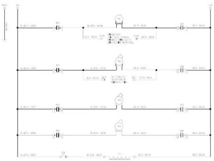
SECTION 6: ELECTRICAL SCHEMATICS
AJ-86CS & AJ-100CS (208-230 VOLT, 60 HZ, SINGLE PHASE) SECONDARY SIDE
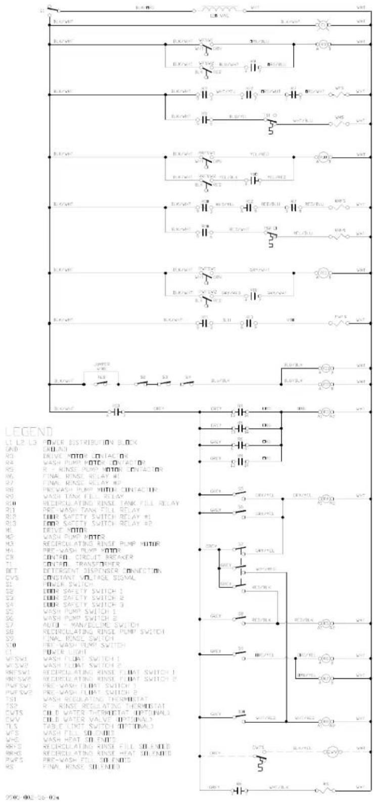
SECTION 6: ELECTRICAL SCHEMATICS
AJ-86CS & AJ-100CS (208-230 VOLT, 60 HZ, THREE PHASE) PRIMARY SIDE
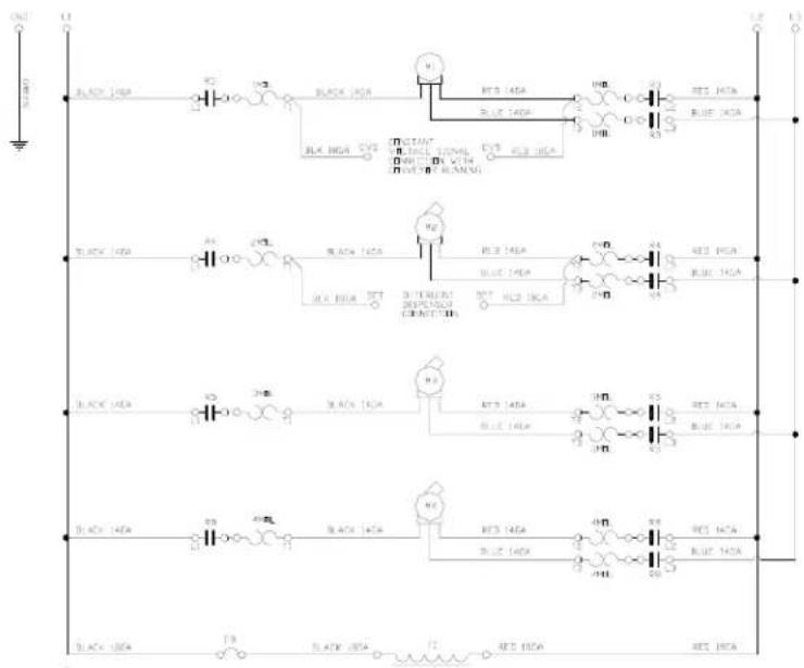
SECTION 6: ELECTRICAL SCHEMATICS
AJ-86CS & AJ-100CS (208-230 VOLT, 60 HZ, THREE PHASE) SECONDARY SIDE
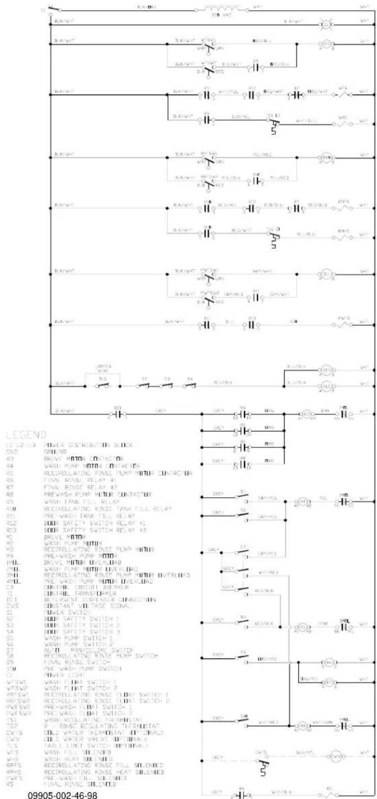
SECTION 6: ELECTRICAL SCHEMATICS
AJ-86CS & AJ-100CS (460 VOLT, 60 HZ, THREE PHASE) PRIMARY SIDE
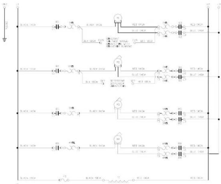
SECTION 6: ELECTRICAL SCHEMATICS
AJ-86CS & AJ-100CS (460 VOLT, 60 HZ, THREE PHASE) SECONDARY SIDE
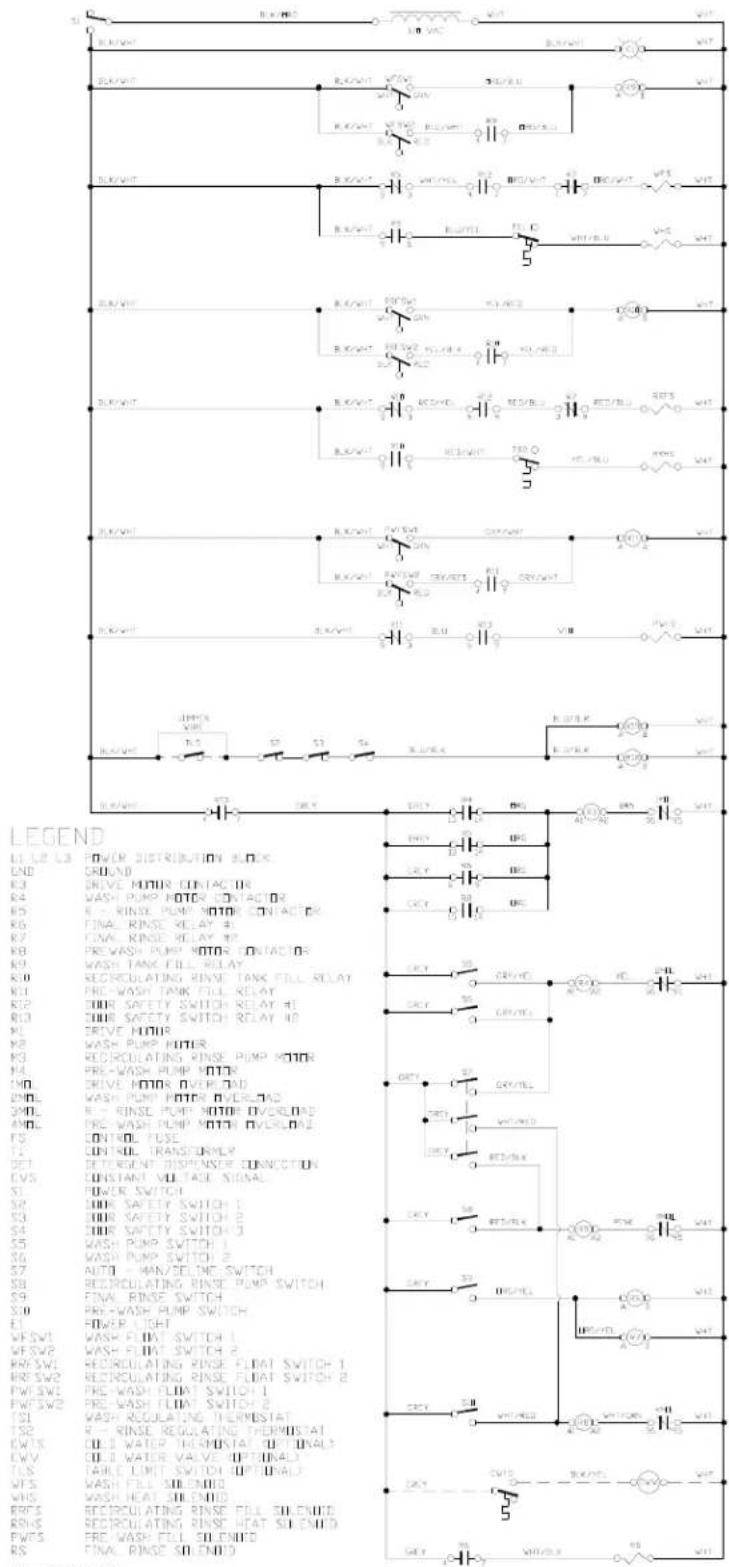
9903-041-93-74n
SECTION 6: ELECTRICAL SCHEMATICS
AJ-86CGP & AJ-100CGP (208-230 VOLTS, 60 HZ, SINGLE PHASE) PRIMARY SIDE
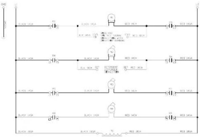
SECTION 6: ELECTRICAL SCHEMATICS
AJ-86CGP & AJ-100CGP (208-230 VOLTS, 60 HZ, SINGLE PHASE) SECONDARY SIDE
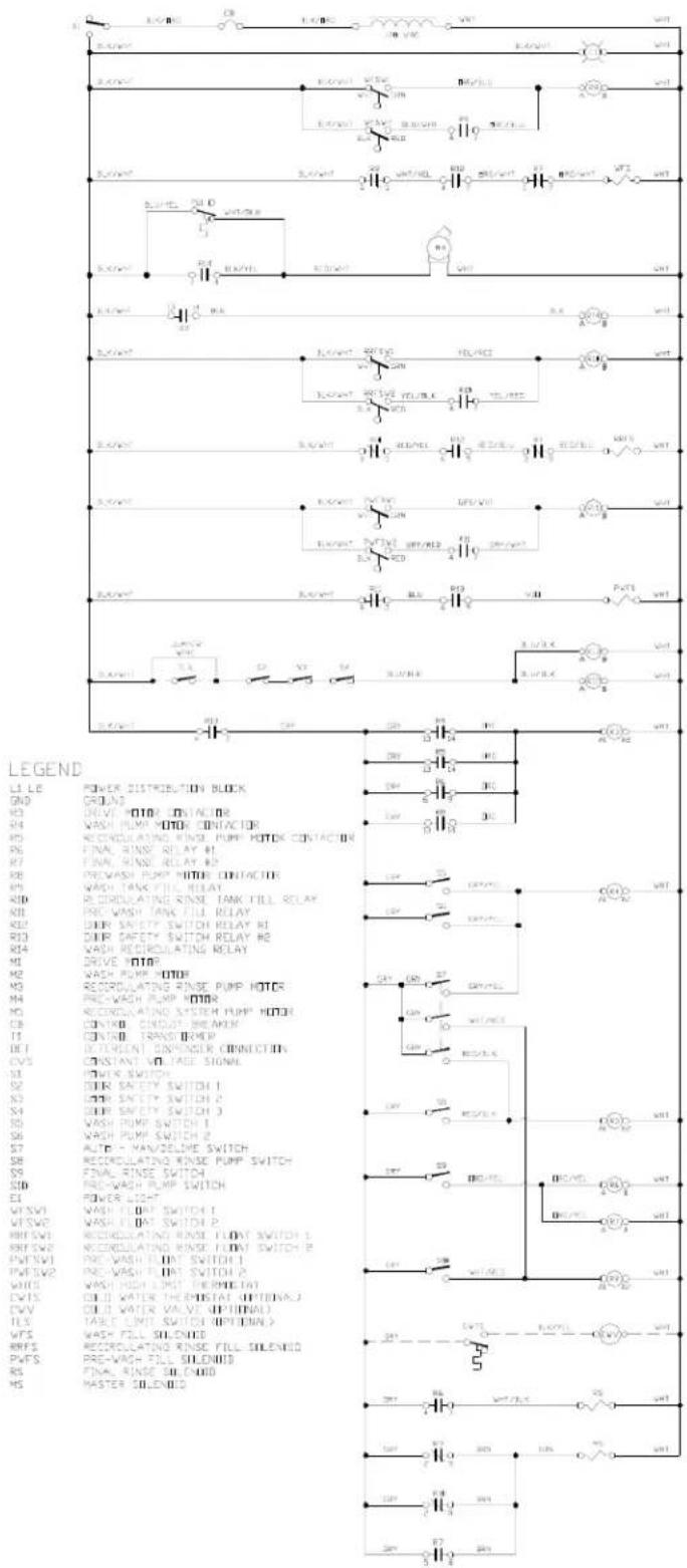
9503-002-60-250
SECTION 6: ELECTRICAL SCHEMATICS
AJ-86CGP & AJ-100CGP (208-230 VOLTS, 60 HZ, THREE PHASE) PRIMARY SIDE
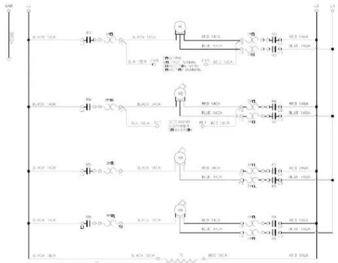
SECTION 6: ELECTRICAL SCHEMATICS
AJ-86CGP & AJ-100CGP (208-230 VOLTS, 60 HZ, THREE PHASE) SECONDARY SIDE
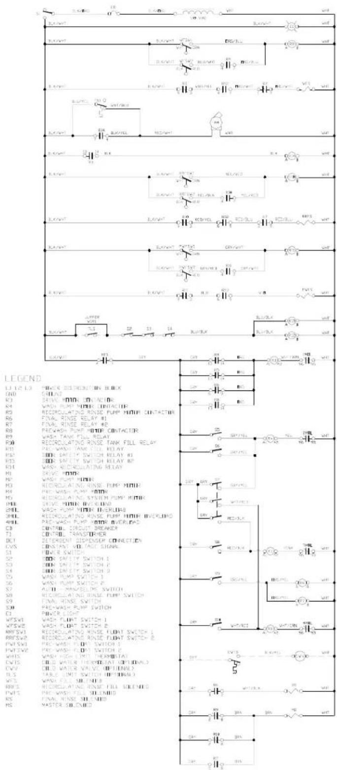
9905-041-86-714
SECTION 6: ELECTRICAL SCHEMATICS
AJ-86CGP & AJ-100CGP (460 VOLTS, 60 HZ, THREE PHASE) PRIMARY SIDE
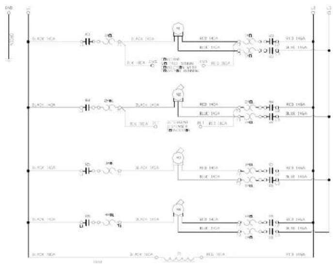
SECTION 6: ELECTRICAL SCHEMATICS
AJ-86CGP & AJ-100CGP (460 VOLTS, 60 HZ, THREE PHASE) SECONDARY SIDE
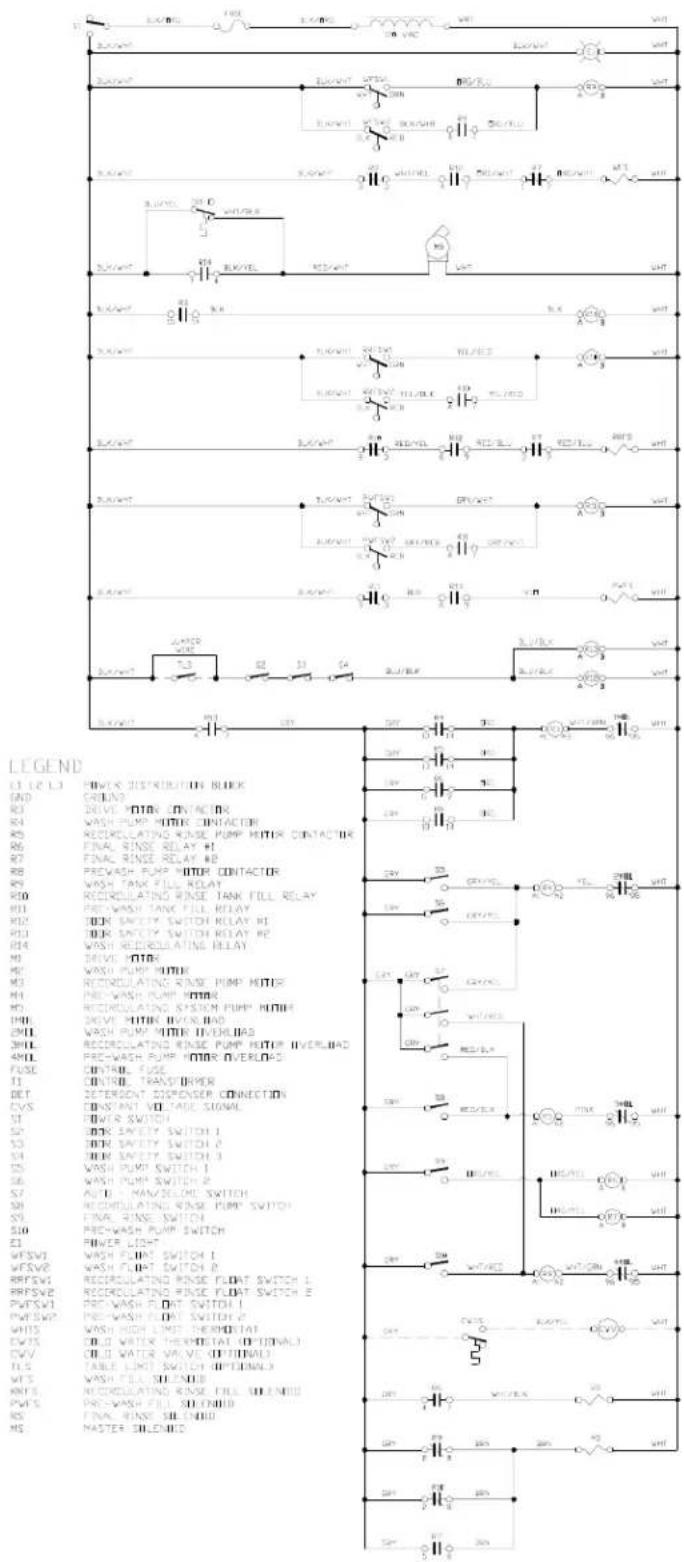
900-002
SECTION 6: ELECTRICAL SCHEMATICS CONVEYOR EXHAUST FAN HOOKUP
CONVEYOR EXHAUST FAN HOOKUP
LEGEND
T TIMER TB TERMINAL BOARD
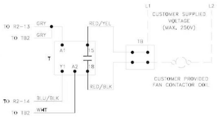
9905-002-55-86b
GAS CONVEYOR EXHAUST FAN HOOKUP
LEGEND
T TIMER TB TERMINAL BOARD
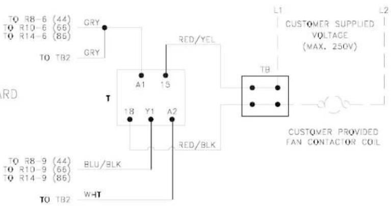
9905-003-14-580
SECTION 6: ELECTRICAL SCHEMATICS
86" & 100" CONVEYORS

SECTION 7: JACKSON MAINTENANCE & REPAIR CENTERS
SECTION 7: JACKSON MAINTENANCE & REPAIR CENTERS
ALABAMA TO FLORIDA
ALABAMA
JONES-McLEOD APPLIANCE SVC
1616 7TH AVE. NORTH BIRMINGHAM, AL 35203
(205) 251-0159
800-821-1150
FAX: (205) 322-1440
service@jones-mcleod.com
JONES-McLEOD APPLIANCE SVC
854 LAKESIDE DRIVE
MOBILE, AL 36693
(251) 666-7278
800-237-9859
FAX: (251) 661-0223
ALASKA
RESTAURANT APPLIANCE SERVICE
7219 ROOSEVELT WAY NE
SEATTLE, WA 98115
(206) 524-8200
800-433-9390
FAX: (206) 525-2890
info@restappl.com
ARIZONA
AUTHORIZED COMMERCIAL FOOD EQMT. SVC
4832 SOUTH 35TH STREET
PHOENIX, AZ 85040
(602) 234-2443
800-824-8875
FAX: (602) 232-5862
acsboss@aol.com
GCS SERVICE INC.
PHOENIX, AZ
(602) 474-4510
800-510-3497
FAX: (602) 470-4511
ARKANSAS
BROMLEY PARTS & SVC
10TH AND RINGO
P.O. BOX 1688
COMMERCIAL APPLIANCE SERVICE, INC.
6507 PACIFIC AVENUE, SUITE 102
STOCKTON, CA 95207
(916) 567-0203
(800) 464-2222
(916) 567-0266 FAX
GCS SERVICE INC.
SAN DIEGO, CA
(858) 549-8411
800-422-7278
FAX: (858) 549-2323
INDUSTRIAL ELECTRIC SVC.
5662 ENGINEER DRIVE
HUNTINGTON BEACH, CA
92649
(714) 379-7100
(800-457-3783
FAX: (714) 379-7109
P & D APPLIANCE SVC
100 SOUTH LINDEN AVE.
S. SAN FRANCISCO, CA 94080
(650) 635-1900
800-424-1414
FAX: (650) 635-1919
pndappl@aol.com
P & D APPLIANCE
4220-C ROSEVILLE ROAD
NORTH HIGHLANDS, CA
95660
(916) 974-2772
800-824-7219
FAX:(916) 974-2774
COMMERCIAL APPLIANCE
SERVICE, INC.
281 LATHROP WAY, #100
METRO APPLIANCE SERVICE
1640 S BROADWAY
DENVER, CO 80210
(303) 778-1126
800-525-3532
FAX: (303) 778-0268
metroappls@aol.com
CONNECTICUT
GCS SERVICE INC.
HARTFORD, CT
(860) 549-5575
800-423-1562
FAX: (860) 527-6355
SUPERIOR KITCHEN SER-
VICE INC.
22 THOMPSON ROAD
WINDSOR, CT 06088
(888) 590-1899
(888) 590-1996 FAX
DELAWARE
FOOD SERVICE EQMT.
2101 PARKWAY SOUTH
BROOMALL, PA 19008
(610) 356-6900
FAX: (610) 356-2038
dancerule@aol.com
GCS SERVICE INC.
PHILADELPHIA, PA
(215)925-6217
800-441-9115
FAX: (215) 925-6208
ELMER SCHULTZ SERVICE
36 BELMONT AVE
WILLMINGTON, DE 19804
(302) 655-8900
800-225-0599
FAX: (302) 656-3673
elmer2@erols.com
EMR SERVICE DIVISION
106 WILLIAMSPORT CIRCLE
SALISBURY, MD 21804
(410) 543-8197
FAX: (410) 548-4038
FLORIDA
COMMERCIAL APPLIANCE SERVICE
8416 LAUREL FAIR CIRCLE
BLDG 6, SUITE 114
TAMPA, FL 33610
(813) 663-0313
800-282-4718
FAX: (813) 663-0212
commercialappliance@world-
net.att.net
GCS SERVICE INC
MIAMI, FL
(305) 621-6666
800-766-8966
FAX: (305) 621-6656
GCS SERVICE INC
ORLANDO, FL
(407) 841-2551
800-338-7322
FAX: (407) 423-8425
NASS PARTS AND SERVICE, INC.
1144 BELVILLE ROAD, UNIT 359
DAYTONA BEACH, FL 32114
(386) 226-2642
(800) 432-2795
(386) 736-7695 FAX
GCS SERVICE INC
TAMPA, FL
(813) 626-6044
800-282-3008
FAX: (813) 621-1174
SECTION 7: JACKSON MAINTENANCE & REPAIR CENTERS
FLORIDA TO MARYLAND
JONES-McLEOD APPLIANCE SVC
854 LAKESIDE DRIVE
MOBILE, AL 36693
(251) 666-7278
800-237-9859
FAX: (251) 661-0223
service@jones-mcleod.com
NASS PARTS AND SERVICE, INC.
1108 SOUTH WOODS AVENUE
ORLANDO, FL 32805
(407) 425-2681
(800) 432-2795
(407) 425-3463 FAX
NASS PARTS AND SERVICE, INC.
1376 HEIDE AVENUE
PALM BAY, FL 32907
(321) 952-2012
(800) 432-2795
(321) 953-0266 FAX
GEORGIA
GCS SERVICE INC
ATLANTA, GA
(770) 452-7322
800-334-3599
FAX: (770) 452-7473
HERITAGE FOODSERVICE GROUP OF ATLANTA
2100 NORCROSS PKWY. SUITE 130
NORCROSS, GA 30071
(770) 368-1465
866-388-9837
FAX: (866) 388-9838
WHALEY FOODSERVICE REPAIRS
109-A OWENS INDUSTRIAL DRIVE
SAVANNAH, GA 31405
(912) 447-0827
888-765-0036
FAX: (912) 447-0826
PIERCE PARTS & SERVICE
2422 ALLEN ROAD
MACON, GA 31216
(478) 781-6003
800-368-2512
FAX: (478) 781-7186
HAWAII
FOOD EQMT. PARTS & SERVICE CO.
300 PUUHALE RD
HONOLULU, HI 96819
(808) 847-4871
FAX: (808) 842-1560
fepsco@hula.net
The Ground Truth image displays a single, solid horizontal line. According to Rule 2 (UNDERSCORE & LINE RULES), this is a stylistic or background line, not a placeholder underscore. Therefore, the OCR result must ignore it and output nothing or only meaningful text. The provided OCR content is "\_\_\_\_", which consists of four underscores. This is an incorrect interpretation of the line as a placeholder, violating the rule that stylistic lines must be ignored. The OCR has hallucinated underscores where none should exist based on the GT's visual context. Hence, the OCR result is inconsistent with the Ground Truth.
RESTAURANT APPLIANCE SVC.
7219 ROOSEVELT WAY NE
SEATTLE, WA 98115
(206) 524-8200
800-433-9390
FAX: (206) 525-2890
info@restappl.com
RON'S SERVICE
703 E 44TH STREET STE 10
GARDEN CITY, ID 83714
(208) 375-4073
FAX: (208) 375-4402
ILLINOIS
CONES REPAIR SVC.
2408 40TH AVE
MOLINE, IL 61265
(309) 797-5323
800-716-7070
FAX: (309)797-3631
jackb@cones.com
EICHENAUER SERVICES INC.
130 S OAKLAND ST.
DECATUR, IL 62522
(217) 429-4229
800-252-5892
FAX: (217) 429-0226
esi@esiquaity.com
GCS SERVICE INC.
ELMHURST, IL
(630) 941-7800
800-942-9689
FAX: (630) 941-6048
GCS SERVICE INC.
ST. LOUIS, MO
(314) 683-7444
800-284-4427
FAX: (314) 638-0135
GENERAL PARTS, INC.
248 JAMES STREET
BENSONVILLE, IL 60106
(630) 595-3300
(800) 880-3604
FAX: (630)595-0006
INDIANA
GCS SERVICE INC.
INDIANAPOLIS, IN
(317) 545-9655
800-727-8710
FAX: (317) 549-6286
B622 LA PAS TRAIL
INDIANAPOLIS, IN 46268
(317) 290-8060
(800) 410-9794
(317) 290-8085 FAX
IOWA
BOWLING GREEN, KY 42101
(270) 783-0012
(877) 907-0012
FAX: (270) 783-0058
CERTIFIED SERVICE CENTER
RAMCO BUSINESS PARK
4283 PRODUCE ROAD
LOUISVILLE, KY 40218
(502) 964-7007
800-637-6350
FAX: (502) 964-7202
cwalker@certifiedsc.com
droenigk@certifiedsc.com
CERTIFIED SERVICE CENTER
1051 GOODWIN DRIVE
LEXINGTON, KY 40505
(606) 254-8854
800-432-9269
FAX: (606) 231-7781
jatkins@certifiedsc.com
GCS SERVICE INC.
LOUISVILLE, KY
(502) 367-1788
800-752-6160
FAX: (502) 367-0400
GCS SERVICE INC.
LEXINGTON, KY
(606) 255-0746
800-432-9260
FAX: (606) 255-0748
LOUISIANA
HERITAGE SERVICE GROUP
1532 RIVER OAKS WEST
NEW ORLEANS, LA 70123
(504) 734-8864
(800) 499-2351
(504) 733-2559 FAX
MAINE
GCS SERVICE INC.
CHELSEA, MA
(617) 889-9393
800-225-1155
FAX: (617) 889-1222
MASSACHUSETTS RESTAU-
RANT SUPPLY
34 SOUTH STREET
SOMERVILLE, MA 02143
(617) 868-1930
800-338-6737
FAX: (617) 686-5331
SECTION 7: JACKSON MAINTENANCE & REPAIR CENTERS
MARYLAND TO NEW YORK
EMR SERVICE DIVISION
106 WILLIAMSPORT CIRCLE
SALISBURY, MD 21804
(410) 543-8197
888-687-8080
FAX: (410) 548-4038
baltparts@emrco.com
EMR SERVICE DIVISION
5316 Sunnyside Ave.
Beltsville, MD 20715
(301) 931-7000
800-348-2365
FAX: (301) 931-3060
baltparts@emrco.com
GCS SERVICE INC.
SILVER SPRING, MD
(301) 585-7550 (DC)
(410) 792-0338 (BALT)
(800) 638-7278
FAX: (301) 495-4410
MASSACHUSETTS
ACE SERVICE CO.
95 HAMPTON AVE.
NEEDHAM, MA 02494
(781) 449-4220
800-225-4510 MA & NH
FAX: (781) 444-4789
taceservice@aol.com
MASSACHUSETTS RESTAURANT SUPPLY
34 SOUTH STREET
SOMERVILLE, MA 02143
(617) 868-1930
800-338-6737
FAX: (617) 868-5331
GCS SERVICE INC.
CHELSEA, MA
(617) 889-9393
800-225-1155
FAX: (617) 889-1222
GCS SERVICE INC.
HARTFORD, CT
(860) 549-5575
800-723-1562
FAX: (860) 527-6355
SUPERIOR KITCHEN SERVICE INC.
399 FERRY STREET
EVERETT, MA 02149
(617) 389-1899
(888) 590-1899
(617) 389-1996 FAX
MICHIGAN
GCS SERVICE INC.
LIVONIA, MI
(248) 426-9500
800-772-2936
FAX: (248) 426-7555
JACKSON SERVICE COMPA-
NY
3980 BENSTEIN RD.
COMMERCE TWSHP, MI 48382
(248) 363-4159
800-332-4053
FAX: (248) 363-5448
GCS SERVICE INC.
GRAND RAPIDS, MI
(616) 241-0200
800-823-4866
FAX: (616) 241-0541
MINNESOTA
GCS SERVICE INC.
MINNEAPOLIS, MN
(612) 546-4221
800-345-4221
FAX: (612) 546-4286
GENERAL PARTS, INC.
11311 HAMPSHIRE AVENUE
SOUTH
BLOOMINGTON, MN 55438-
2456
(952) 944-5800
(800) 279-9980
(800) 279-9980 FAX
MISSISSIPPI
GCS SERVICE INC.
JACKSON, MS
(601) 956-7800
800-274-5954
FAX: (601) 956-1200
GCS SERVICE INC.
MEMPHIS, TN
(901) 366-4587
800-262-9155
FAX: (901) 366-4588
MISSOURI
GCS SERVICE INC.
KANSAS CITY, MO
(816) 920-5999
800-229-6477
FAX: (816) 920-7387
GCS SERVICE INC.
ST. LOUIS, MO
(314) 638-7444
800-284-4427
FAX: (314) 638-0135
KAEMMERLIN PARTS & SVC.
2728 LOCUST STREET
ST. LOUIS, MO 63103
(314) 535-2222
FAX: (314) 535-6205
petek@kps.stl.com
GENERAL PARTS, INC.
1101 EAST 13TH STREET
KANSAS CITY, MO 64106
(816) 421-5400
(800) 279-9967
(816) 421-1270 FAX
MONTANA
RESTAURANT APPLIANCE
SVC.
7219 ROOSEVELT WAY NE
SEATTLE, WA 98115
(206) 524-8200
800-433-9390
FAX: (206) 525-2890
info@restappl.com
NEBRASKA
201 W. WASHINGTON AVE.
PLEASANTVILLE, NJ 08232
(609) 641-0317
800-378-1641
FAX:(609) 641-8703
elmer2@erols.com
NEW YORK
APPLIANCE INSTALLATION
AND SERVICE CORP.
1336 MAIN STREET
BUFFALO, NY 14209
(716) 884-7425
800-722-1252
FAX: (716) 884-0410
ais@worldnet.att.net
SECTION 7: JACKSON MAINTENANCE & REPAIR CENTERS
NEW YORK TO PENNSYLVANIA
B.E.S.T. INC.
3003 GENESEE STREET
BUFFALO, NY 14225
(716) 893-6464
800-338-5011
FAX: (716) 893-6466
bestserv@aol.com
DUFFY'S EQUIPMENT SVC.
3138 ONEIDA STREET
SAUQUOIT, NY 13456
(315) 737-9401
800-443-8339
FAX: (315) 737-7132
duffyequip@aol.com
NORTHERN PARTS & SVC.
21 NORTHERN AVENUE
PLATTSBURGH, NY 12903
(518) 563-3200
800-634-5005
FAX: (800) 782-5424
info@northernparts.com
GCS SERVICE INC.
BROOKLYN, NY
(718) 486-5220
800-969-4271
FAX: (718) 486-6772
ALL SERVICE KITCHEN
EQUIPMENT REPAIR
10 CHARLES ST.
NEW HYDE PARK, NY 11040
(516) 378-1176
FAX: (516) 378-1735
ALL ISLAND REPAIRS
40-9 BURT DRIVE
DEER PARK, NY 11729
(631) 242-5588
FAX: (631) 242-6102
NORTH CAROLINA
AUTHORIZED APPLIANCE
SERVICECENTER
1020 TUCKASEEGEE RD.
CHARLOTTE, NC 28208
(704) 377-4501
(800) 532-6127
FAX:(704) 377-4504
AUTHORIZED APPLIANCE
SERVICECENTER
800 N. PERSON ST.
RALEIGH, NC 27604
(919) 834-3476
FAX:(919) 834-3477
AUTHORIZED APPLIANCE SERVICECENTER
904 S. MARSHALL ST.
WINSTON-SALEM, NC 27403
(336) 725-5396
FAX:(336) 721-1289
AUTHORIZED APPLIANCE SERVICECENTER
104 HINTON AVE.
WILMINGTON, NC 28403
(910) 313-1250
FAX:(910) 313-6130
WHALEY FOODSERVICE
8334-K ARROWRIDGE BLVD
CHARLOTTE, NC 28273
(704) 529-6242
FAX: (704) 529-1558
info@whaleyfoodservice.com
WHALEY FOODSERVICE REPAIRS
203-D CREEK RIDGE RD.
GREENSBORO, NC 27406
(336) 333-2333
FAX: (336) 333-2533
info@whaleyfoodservice.com
WHALEY FOODSERVICE REPAIRS
335-105 SHERWEE DRIVE
RALEIGH, NC 27603
(919) 779-2266
FAX: (919) 779-2224
info@whaleyfoodservice.com
WHALEY FOODSERVICE REPAIRS
6418-101 AMSTERDAM WAY
WILMINGTON, NC 28405
(910) 791-0000
FAX: (910) 791-6662
info@whaleyfoodservice.com
NORTH DAKOTA
GCS SERVICE INC.
MINNEAPOLIS, MN
(612) 546-4221
800-345-4221
FAX: (612) 546-4286
GENERAL PARTS, INC.
10 SOUTH 18TH STREET
FARGO, ND 58103
(701) 235-4161
(800) 279-9987
(701) 235-0539 FAX
OHIO
CERTIFIED SERVICE CENTER
890 REDNA TERRACE
CINCINNATI, OH 45215
(513) 772-6600
800-543-2060
FAX: (513) 612-6600
sbarasch@certifiedsc.com
CERTIFIED SERVICE CENTER
171J-K NORTH HAMILTON RD.
COLUMBUS, OH 43213
(614) 751-3769
(866) 862-1252
FAX: (614) 751-5792
jadkins@certifiedsc.com
CERTIFIED SERVICE CENTER
6025 N. DIXIE DRIVE
DAYTON, OH 45414
(937) 898-4040
(800) 257-2611
FAX: (937) 898-4177
dharvey@certifiedsc.com
COMMERCIAL PARTS & SVC. OF COLUMBUS
5033 TRANSAMERICA DRIVE
COLUMBUS, OH 43228
(614) 221-0057
800-837-8327
FAX: (614) 221-3622
GCS SERVICE INC.
COLUMBUS, OH
(614) 476-3225
800-282-5406
FAX: (614) 476-1196
ELECTRICAL APPLIANCE REPAIR SVC.
5805 VALLEY BELT ROAD
CLEVELAND, OH 44131
(216) 459-8700
800-621-8259
FAX: (216) 459-8707
tomr@electapplrep.com
OKLAHOMA
HAGAR RESTAURANT EQMT.
1229 W MAIN STREET
OKLAHOMA CITY, OK 73106
(405) 235-2184
800-445-1791
FAX: (405) 236-5592
OREGON
RON'S SERVICE
16364 SW 72ND AVE
PORTLAND, OR 97224
(503) 624-0890
800-851-4118
FAX: (503) 684-6107
Irobinson@ronsservice.com
PENNSYLVANIA
A.I.S. COMMERCIAL PARTS & SERVICE
1816 WEST 26TH STREET
ERIE, PA 16508
(814) 456-3732
800-332-3732
FAX: (814) 452-4843
aiserie@aol.com
ELMER SCHULTZ SVC.
540 NORTH 3RD STREET
PHILADELPHIA, PA 19123
(215) 627-5400
FAX: (215) 627-5408
elmer2@erols.com
GCS SERVICE INC.
PHILADELPHIA, PA
(215) 925-6217
800-441-9115
FAX: (215) 925-6208
GCS SERVICE INC.
HARRISBURG, PA
(717) 564-3282
800-367-3225
FAX: (717) 564-9286
GCS SERVICE INC.
PITTSBURGH, PA
(412) 787-1970
800-738-1221
FAX: (412) 787-5005
K & D PARTS AND SERVICE
CO.
1833-41 N CAMERON STREET
HARRISBURG, PA 17103
(717) 236-9039
800-932-0503
FAX: (717) 238-4367
kdparts-service@paonline.com
CLARK SERVICE & PARTS
306 AIRPORT DRIVE
BOX 10
SMOKETOWN, PA 17576
(717) 392-5590
(717) 392-5735
SECTION 7: JACKSON MAINTENANCE & REPAIR CENTERS
RHODE ISLAND TO WISCONSIN
RHODE ISLAND
GCS SERVICE INC.
EAST PROVIDENCE, RI
(401) 434-6803
800-462-6012
FAX: (401) 438-9400
SUPERIOR KITCHEN SERVICE INC.
669 ELMWOOD AVENUE
PROVIDENCE, RI 02907
(888) 590-1899
(401) 781-1996 FAX
SOUTH CAROLINA
AUTHORIZED APPLIANCE SERVICECENTER
1811 TAYLOR ST.
COLUMBIA, SC 29202
(803) 254-8414
FAX: (803) 254-5146
AUTHORIZED APPLIANCE SERVICECENTER
2249 AUGUSTA RD.
GREENVILLE, SC 29605
(864) 235-9616
FAX: (864) 235-9623
WHALEY FOODSERVICE REPAIRS
I 26&US1
P.O. BOX 4023
WEST COLUMBIA, SC 29170
(803) 791-4420
800-877-2662
FAX: (803) 794-4630
info@whaleyfoodservice.com
WHALEY FOODSERVICE REPAIRS
748 CONGAREE ROAD
GREENVILLE, SC 29607
(864) 234-7011
800-494-2539
FAX: (864) 234-6662
info@whaleyfoodservice.com
WHALEY FOODSERVICE REPAIRS
1406-C COMMERCE PL
MYRTLE BEACH, SC 29577
(843) 626-1866
FAX: (843) 626-2632
info@whaleyfoodservice.com
WHALEY FOODSERVICE REPAIRS
4740-A FRANCHISE STREET
N. CHARLESTON, SC 29418
(843) 760-2110
FAX: (843) 760-2255
info@whaleyfoodservice.com
SOUTH DAKOTA
GCS SERVICE INC.
MINNEAPOLIS, MN
(612) 546-4221
800-345-4221
FAX: (612) 546-4286
GENERAL PARTS, INC.
10 SOUTH 18TH STREET
FARGO, ND 58103
(701) 235-4161
(800) 279-9987
(701) 235-0539 FAX
TENNESSEE
GCS SERVICE INC.
MEMPHIS, TN
(901) 366-4587
800-262-9155
FAX: (901) 366-4588
GCS SERVICE INC.
NASHVILLE, TN
(615) 244-8050
800-831-7174
FAX: (615) 244-8885
TEXAS
ARMSTRONG REPAIR CEN- TER
5110 GLENMOUNT DRIVE
HOUSTON, TX 77081
(713) 666-7100
800-392-5325
FAX: (713) 661-0520
gm@armstrongrepair.com
COMMERCIAL KITCHEN REPAIR CO.
1377 N BRAZOS
P.O BOX 831128
SAN ANTONIO, TX 78207
(210) 735-2811
800-292-2120
FAX: (210) 735-7421
brock@commercialkitchen.com
GCS SERVICE INC.
DALLAS, TX
(972) 484-2954
800-442-5026
FAX: (972) 484-2531
GCS SERVICE INC.
HOUSTON, TX
(713)785-9187
800-868-6957
FAX: (713) 785-3979
GCS/STOVE PARTS
2120 SOLANA STREET
FORT WORTH, TX 76117
(817) 831-0381
800-433-1804
FAX: (817) 834-7754
bud@stoveparts.com
UTAH
LA MONICA'S RESTAURANT EQMT. SVC.
6182 SOUTH STRATLER
AVENUE
MURRAY, UT 84107
(801) 263-3221
800-527-2561
FAX: (801) 263-3229
lamonica81@aol.com
VERMONT
NORTHERN PARTS & SVC.
4874 S. CATHERINE STREET
PLATTSBURGH, NY 12901
(518) 563-3200
800-634-5005
FAX: (800) 782-5424
info@northernparts.com
GCS SERVICE INC.
CHELSEA, MA
(617)889-9393
800-225-1155
FAX: (617) 889-1222
VIRGINIA
DAUBERS, INC.
7645 DYNATECH COURT
SPINGFIELD, VA 22153
(703) 866-3600
800-554-7788
FAX: (703) 866-4071
daubers@aol.com
GCS SERVICE INC.
SILVER SPRING, MD
(301) 585-7550(DC)
(410) 792-0388(BALT)
800-638-7278
FAX: (301)495-4410
GCS SERVICE INC.
RICHMOND, VA
(804) 672-1700
800-899-5949
FAX: (804) 672-2888
GCS SERVICE INC.
VIRGINIA BEACH, VA
(757) 464-3500
800-476-4278
FAX: (757) 464-4106
WASHINGTON
GCS SERVICE INC.
SEATTLE, WA
(206) 763-0353
800-211-4274
FAX: (206) 763-5943
RESTAURANT APPLIANCE SERVICE
7219 ROOSEVELT WAY, NE
SEATTLE, WA 98115
(206) 524-8200
800-433-9390
FAX: (206) 525-2890
info@restappl.com
WEST VIRGINIA
STATEWIDE SERVICE, INC.
603 MAIN AVE
NITRO, WV 25143
(304) 755-1811
(800) 441-9739
FAX: (304) 755-4001
sws3182@aol.com
WISCONSIN
APPLIANCE SERVICE CENTER, INC.
2439 ATWOOD AVE
MADISON, WI 53704
(608) 246-3160
800-236-7440
FAX: (608) 246-2721
ascmad@execpc.com
APPLIANCE SERVICE
CENTER, INC.
6843 W. BELOIT RD.
WEST ALLIS, WI 53219
(414) 543-6460
800-236-6460
FAX: (414) 543-6480
ascmil@execpc.com
APPLIANCE SERVICE
CENTER
786 MORRIS AVE
GREEN BAY, WI 54304
(920) 496-9993
800-236-0871
FAX: (920) 496-9927
ascfox@execpc.com
SECTION 7: JACKSON MAINTENANCE & REPAIR CENTERS
WISCONSIN TO WYOMING/INTERNATIONAL
GENERAL PARTS, INC.
W223 N735 SARATOGA DRIVE
WAUKESHA, WI 53186
(262) 650-6666
(800) 279-9946
(262) 650-6660 FAX
WYOMING
HAWKINS COMMERCIAL
APPLIANCE SERVICE
3000 S. WYANDOT ST.
ENGLEWOOD, CO 80110
(303) 781-5548
(800) 624-2117
FAX: (303) 761-5561
johns@hawkinscommercial.com
METRO APPLIANCE SERVICE
1640 S BROADWAY
DENVER, CO 80210
(303) 778-1126
800-525-3532
FAX: (303) 778-0268
metroappls@aol.com
INTERNATIONAL
GLOBAL PARTS AND SUPPLY
7758 NW 72ND ST
MIAMI, FL 33166
(305) 885-6353
H.D. SHELDON AND CO
19 UNION SQUARE, WEST
NEW YORK, NY 10003
(212) 627-1759
(212) 924-6920
CANADA
THE GARLAND GROUP
1177 KAMATO ROAD
MISSISSAUGA, ONTARIO L4W
1×4
(905) 206-8380
SALES
(905) 624-1419
FAX: (905) 624-1851
SERVICE
800-427-6668
FAX: 800-361-7745
March 13, 2007
- MANUFACTURERS WARRANTY
- ONE YEAR LIMITED PARTS & LABOR WARRANTY
- TRAVEL LIMITATIONS
- WARRANTY REGISTRATION CARD
- REPLACEMENT PARTS WARRANTY
- PRODUCT CHANGES AND UPDATES
- ITEMS NOT COVERED
- STOP!
- PARE!
- ARRET!
- AJ-64CS
- TABLE OF CONTENTS
- SECTION DESCRIPTION PAGE
- SPECIFICATION INFORMATION
- INSTALLATION & OPERATION INSTRUCTIONS
- PREVENTATIVE MAINTENANCE
- TROUBLESHOOTING SECTION
- PARTS
- PARTS SECTION
- SIDE LOADER SECTION
- D226 STEAM BOOSTER SECTION
- ELECTRICAL SCHEMATICS
- ELECTRICAL SCHEMATICS
- SECTION 1: SPECIFICATION INFORMATION
- SECTION 1: SPECIFICATION INFORMATION OPERATING CHARACTERISTICS
- RACKS PER HOUR:
- DISHES OR GLASSES PER HOUR:
- PREWASH TANK CAPACITY (GALLONS):
- WASH TANK CAPACITY (GALLONS):
- POWER RINSE TANK CAPACITY (GALLONS):
- PREWASH PUMP CAPACITY (GPM):
- WASH PUMP CAPACITY
- POWER RINSE PUMP CAPACITY
- VENTING REQUIREMENTS (CFM)(100% CAP.):
- CONVEYOR SPEED (FPM):
- GALLONS PER RACK:
- WATER TEMPERATURES:
- AJ-64-86-100CE/CS/CGP MODELS:
- FLOWRATE (GPM):
- STEAM COIL TANK HEAT (CS MODELS ONLY):
- MOTOR ELECTRICAL CHARACTERISTICS:
- ELECTRICAL REQUIREMENTS
- ELECTRICAL REQUIREMENTS (CONTINUED)/D226 STEAM BOOSTER PARAMETERS
- AJ-64 ELECTRIC - RIGHT TO LEFT
- Right to Left
- Recommended Table Fabrication
- AJ-86 GAS - LEFT TO RIGHT
- AJ-86 GAS - RIGHT TO LEFT
- Right to Left Legend
- AJ-100 GAS - LEFT TO RIGHT
- AJ-100 GAS - RIGHT TO LEFT
- SECTION 1: SPECIFICATION INFORMATION SIDE LOADER INSTALLATION DIMENSIONS
- SECTION 1: SPECIFICATION INFORMATION D226 STEAM BOOSTER DIMENSIONS
- SECTION 1: SPECIFICATION INFORMATION TYPICAL ELECTRIC AND GAS BOOSTER DIMENSIONS
- SECTION 2: INSTALLATION/OPERATION INSTRUCTIONS
- INSTALLATION INSTRUCTIONS
- NOTE: THE INSTRUCTIONS PROVIDED HEREIN, UNLESS OTHERWISE SPECIFIED ARE FOR THE DISHMA-CHINES ONLY. THERE ARE SEPARATE DIRECTIONS FOR THE GAS BOOSTER.
- SECTION 2: INSTALLATION/OPERATION INSTRUCTIONS INSTALLATION INSTRUCTIONS (CONTINUED)
- INSTALLATION INSTRUCTIONS (CONTINUED)
- DELIMING OPERATIONS
- CURTAIN INSTALLATION DIAGRAMS
- SECTION 2: INSTALLATION/OPERATION INSTRUCTIONS SIDE LOADER INSTALLATION & OPERATION INSTRUCTIONS
- D226 STEAM BOOSTER INSTALLATION & OPERATION INSTRUCTIONS
- CONCEALED DAMAGE OR MISSING PARTS:
- IMPORTANT: FOR YOUR PROTECTION, PLEASE READ AND OBSERVE THE FOLLOWING:
- EQUIPMENT MOUNTING:
- PLUMBING:
- NOTE: ALL CONNECTIONS MUST COMPLY WITH ALL APPLICABLE LOCAL, STATE AND NATIONAL PLUMBING CODES.
- D226 STEAM BOOSTER INSTALLATION & OPERATION INSTRUCTIONS (CONTINUED)
- ELECTRICAL:
- OPERATION:
- SHUTDOWN (FOR SERVICE ONLY):
- GAS CONVEYOR HOSE INSTALLATION (CONTINUED)
- SECTION 2: INSTALLATION/OPERATION INSTRUCTIONS DISHMACHINE OPERATING INSTRUCTIONS
- SECTION 2: INSTALLATION/OPERATION INSTRUCTIONS DISHMACHINE OPERATION INSTRUCTIONS (CONTINUED)
- SECTION 2: INSTALLATION/OPERATION INSTRUCTIONS DETERGENT CONTROL
- STRIKER PLATE LIMIT SWITCH INSTALLATION INSTRUCTIONS
- Installation Instructions:
- SECTION 3: PREVENTATIVE MAINTENANCE
- SECTION 3: PREVENTATIVE MAINTENANCE PREVENTATIVE MAINTENANCE
- SECTION 3: PREVENTATIVE MAINTENANCE D226 MAINTENANCE
- MAINTENANCE OF THE WATER PRESSURE REGULATOR:
- MAINTENANCE OF THE RELIEF VALVES, SAFETY VALVES AND THERMOSTAT:
- LUBRICATION CHART FOR DRIVE GEAR
- SECTION 3: PREVENTATIVE MAINTENANCE DRIVE MOTOR GEAR REDUCER PREVENTATIVE MAINTENANCE
- Lubrication & Maintenance:
- Nominal Ratio
- SECTION 4: TROUBLESHOOTING SECTION
- SECTION 4: TROUBLESHOOTING COMMON PROBLEMS
- Problem: Pawl bar does not move.
- Problem: Racks go through the machine, but results are poor.
- Problem: Spotting of silverware, glasses and dishes.
- TORQUE SETTINGS
- ITEMS
- TORQUE SPEC
- SECTION 4: TROUBLESHOOTING
- D226 TROUBLESHOOTING SECTION
- Problem: Power light does not illuminate.
- Problem: Water pressure is too low.
- Problem: Solenoid valve is not opening/shutting.
- Problem: Outlet water temperature too low.
- SECTION 5: PARTS SECTION
- AJ-64 CONTROL BOX ASSEMBLY (CONTINUED)
- ITEM QTY DESCRIPTION Mfg. No.
- AJ-86 & AJ-100 CONTROL BOX ASSEMBLY (CONTINUED)
- SECTION 5: PARTS SECTION MOTOR OVERLOADS
- AJ-64 SERIES MOTOR OVERLOAD CHART:
- AJ-86 SERIES MOTOR OVERLOAD CHART:
- AJ-100 SERIES MOTOR OVERLOAD CHART:
- SECTION 5: PARTS SECTION HEATER BOX ASSEMBLY
- SECTION 5: PARTS SECTION HEATER ASSEMBLY (CONTINUED)
- A- Checkout of the heater system
- B- If heater relay (R1) closes:
- C - If heater relay (R1) does not close.
- HEATER PROTECTION & AUTOMATIC FILL
- FRAME WELDMENTS/DRESS PANELS
- FRAME WELDMENTS
- FRONT DRESS PANELS
- INCOMING PLUMBING ASSEMBLY (ELECTRIC & GAS HEATED MODELS)
- INCOMING PLUMBING ASSEMBLY(CONTINUED)
- RINSE HEADER PLUMBING ASSEMBLY (CGP MODELS)
- EXTERNAL ELECTRIC BOOSTER INCOMING PLUMBING ASSEMBLIES
- EXTERNAL ELECTRIC BOOSTER OPTION OUTLET PLUMBING
- WATER HAMMER ARRESTOR OPTION/WATER PRESSURE REGULATOR KIT OPTION
- RINSE SOLENOID VALVE & VACUUM BREAKER REPAIR PARTS KITS
- Possible Problems:
- STEAM INLET PLUMBING ASSEMBLY (LEFT TO RIGHT MODELS) (CONTINUED)
- STEAM INLET PLUMBING ASSEMBLY (RIGHT TO LEFT MODELS)(CONTINUED)
- STEAM OUTLET PLUMBING (LEFT TO RIGHT)
- AJ-86 GAS COIL ASSEMBLY (CGP MODELS)
- TANK, RINSE BOOSTER (CGP MODELS ONLY)
- RECIRCULATING PUMP ASSEMBLY (CGP MODELS ONLY)
- HOSE CONNECTIONS (CGP MODELS ONLY)
- HOSE ASSEMBLIES
- AJ-86CGP (L-R & R-L)
- AJ-100CGP (L-R)
- AJ-64 DRAIN PLUMBING ASSEMBLY
- AJ-86 & AJ-100 DRAIN PLUMBING ASSEMBLY (LEFT TO RIGHT MODELS)
- AJ-86 & AJ-100 DRAIN PLUMBING ASSEMBLY (RIGHT TO LEFT MODELS)
- SECTION 5: PARTS SECTION PREWASH & WASH PUMP WELDMENT
- DRIVE ASSEMBLY (CONTINUED)
- Replacement Kits Notes:
- PAWL BAR MISCELLANEOUS COMPONENTS
- Replacement Kit Notes:
- PAWL BAR ASSEMBLIES
- PAWL BAR WELDMENT
- AJ-86 RIGHT TO LEFT WITH A SIDE LOADER
- SECTION 5: PARTS SECTION RACK RAIL ASSEMBLIES
- LEFT TO RIGHT:
- RIGHT TO LEFT:
- MISCELLANEOUS PARTS AND WELDMENTS
- Replacement Kit Note:
- FLOAT SWITCH COMPONENTS/SCRAP BASKETS
- Service Agent Note:
- EXHAUST FAN CONTROL/TABLE LIMIT SWITCH OPTIONS
- SIDE LOADER TRACK ASSEMBLY/LEG REPLACEMENTS/STRAINER
- SIDE LOADER VENT COWL OPTION
- Service Note:
- D226 STEAM BOOSTER CONTROL BOX ASSEMBLY
- D226 STEAM BOOSTER PLUMBING ASSEMBLY
- D226 STEAM BOOSTER PLUMBING ASSEMBLY (CONTINUED)
- GO\*BOX COMPONENTS
- QTY DESCRIPTION Mfg. No.
- SECTION 6: ELECTRICAL SCHEMATICS
- AJ-64CE (208-230 VOLT, 60 HZ, SINGLE PHASE) PRIMARY SIDE
- AJ-64CE (208-230 VOLT, 60 HZ, SINGLE PHASE) SECONDARY SIDE
- AJ-64CE (208-230 VOLT, 60 HZ, THREE PHASE) PRIMARY SIDE
- AJ-64CE (460 VOLT, 60 HZ, THREE PHASE) PRIMARY SIDE
- AJ-64CS (208-230 VOLT, 60 HZ, SINGLE PHASE) PRIMARY SIDE
- AJ-64CS (208-230 VOLT, 60 HZ, THREE PHASE) PRIMARY SIDE
- AJ-64CS (460 VOLT, 60 HZ, THREE PHASE) PRIMARY SIDE
- AJ-86CE & AJ-100CE (208-230 VOLT, 60 HZ, SINGLE PHASE) PRIMARY SIDE
- AJ-86CE & AJ-100CE (208-230 VOLT, 60 HZ, SINGLE PHASE) SECONDARY SIDE
- AJ-86CE & AJ-100CE (208-230 VOLT, 60 HZ, THREE PHASE) PRIMARY SIDE
- AJ-86CE & AJ-100CE (208-230 VOLT, 60 HZ, THREE PHASE) SECONDARY SIDE
- AJ-86CE & AJ-100CE (460 VOLT, 60 HZ, THREE PHASE) PRIMARY SIDE
- AJ-86CE & AJ-100CE (460 VOLT, 60 HZ, THREE PHASE) SECONDARY SIDE
- AJ-86CS & AJ-100CS (208-230 VOLT, 60 HZ, SINGLE PHASE) SECONDARY SIDE
- AJ-86CS & AJ-100CS (208-230 VOLT, 60 HZ, THREE PHASE) PRIMARY SIDE
- AJ-86CS & AJ-100CS (208-230 VOLT, 60 HZ, THREE PHASE) SECONDARY SIDE
- AJ-86CS & AJ-100CS (460 VOLT, 60 HZ, THREE PHASE) PRIMARY SIDE
- AJ-86CS & AJ-100CS (460 VOLT, 60 HZ, THREE PHASE) SECONDARY SIDE
- AJ-86CGP & AJ-100CGP (208-230 VOLTS, 60 HZ, SINGLE PHASE) SECONDARY SIDE
- AJ-86CGP & AJ-100CGP (208-230 VOLTS, 60 HZ, THREE PHASE) SECONDARY SIDE
- AJ-86CGP & AJ-100CGP (460 VOLTS, 60 HZ, THREE PHASE) PRIMARY SIDE
- AJ-86CGP & AJ-100CGP (460 VOLTS, 60 HZ, THREE PHASE) SECONDARY SIDE
- SECTION 6: ELECTRICAL SCHEMATICS CONVEYOR EXHAUST FAN HOOKUP
- SECTION 7: JACKSON MAINTENANCE & REPAIR CENTERS
- ALABAMA TO FLORIDA
- ALABAMA
- JONES-McLEOD APPLIANCE SVC
- ALASKA
- RESTAURANT APPLIANCE SERVICE
- ARIZONA
- AUTHORIZED COMMERCIAL FOOD EQMT. SVC
- GCS SERVICE INC.
- ARKANSAS
- BROMLEY PARTS & SVC
- COMMERCIAL APPLIANCE SERVICE, INC.
- INDUSTRIAL ELECTRIC SVC.
- P & D APPLIANCE SVC
- P & D APPLIANCE
- COMMERCIAL APPLIANCE
- SERVICE, INC.
- METRO APPLIANCE SERVICE
- CONNECTICUT
- SUPERIOR KITCHEN SER-
- VICE INC.
- DELAWARE
- FOOD SERVICE EQMT.
- ELMER SCHULTZ SERVICE
- EMR SERVICE DIVISION
- FLORIDA
- COMMERCIAL APPLIANCE SERVICE
- GCS SERVICE INC
- NASS PARTS AND SERVICE, INC.
- FLORIDA TO MARYLAND
- GEORGIA
- HERITAGE FOODSERVICE GROUP OF ATLANTA
- WHALEY FOODSERVICE REPAIRS
- PIERCE PARTS & SERVICE
- HAWAII
- FOOD EQMT. PARTS & SERVICE CO.
- The Ground Truth image displays a single, solid horizontal line. According to Rule 2 (UNDERSCORE & LINE RULES), this is a stylistic or background line, not a placeholder underscore. Therefore, the OCR result must ignore it and output nothing or only meaningful text. The provided OCR content is "\_\_\_\_", which consists of four underscores. This is an incorrect interpretation of the line as a placeholder, violating the rule that stylistic lines must be ignored. The OCR has hallucinated underscores where none should exist based on the GT's visual context. Hence, the OCR result is inconsistent with the Ground Truth.
- RESTAURANT APPLIANCE SVC.
- RON'S SERVICE
- ILLINOIS
- CONES REPAIR SVC.
- EICHENAUER SERVICES INC.
- GENERAL PARTS, INC.
- INDIANA
- IOWA
- CERTIFIED SERVICE CENTER
- RAMCO BUSINESS PARK
- LOUISIANA
- HERITAGE SERVICE GROUP
- MAINE
- MASSACHUSETTS RESTAU-
- RANT SUPPLY
- MARYLAND TO NEW YORK
- MASSACHUSETTS
- ACE SERVICE CO.
- MASSACHUSETTS RESTAURANT SUPPLY
- SUPERIOR KITCHEN SERVICE INC.
- MICHIGAN
- JACKSON SERVICE COMPA-
- NY
- MINNESOTA
- MISSISSIPPI
- MISSOURI
- KAEMMERLIN PARTS & SVC.
- MONTANA
- RESTAURANT APPLIANCE
- SVC.
- NEBRASKA
- NEW YORK
- APPLIANCE INSTALLATION
- AND SERVICE CORP.
- NEW YORK TO PENNSYLVANIA
- B.E.S.T. INC.
- DUFFY'S EQUIPMENT SVC.
- NORTHERN PARTS & SVC.
- ALL SERVICE KITCHEN
- ALL ISLAND REPAIRS
- NORTH CAROLINA
- AUTHORIZED APPLIANCE
- AUTHORIZED APPLIANCE SERVICECENTER
- WHALEY FOODSERVICE
- NORTH DAKOTA
- OHIO
- COMMERCIAL PARTS & SVC. OF COLUMBUS
- ELECTRICAL APPLIANCE REPAIR SVC.
- OKLAHOMA
- HAGAR RESTAURANT EQMT.
- OREGON
- PENNSYLVANIA
- A.I.S. COMMERCIAL PARTS & SERVICE
- ELMER SCHULTZ SVC.
- K & D PARTS AND SERVICE
- CLARK SERVICE & PARTS
- RHODE ISLAND TO WISCONSIN
- RHODE ISLAND
- SOUTH CAROLINA
- SOUTH DAKOTA
- TENNESSEE
- TEXAS
- UTAH
- VERMONT
- VIRGINIA
- WASHINGTON
- WEST VIRGINIA
- WISCONSIN
- WISCONSIN TO WYOMING/INTERNATIONAL
- WYOMING
- HAWKINS COMMERCIAL
- APPLIANCE SERVICE
- INTERNATIONAL
- GLOBAL PARTS AND SUPPLY
- H.D. SHELDON AND CO
- CANADA
- THE GARLAND GROUP
Brand : Jackson
Model : AJ-86
Category : Dishwasher