
EC9208 - Programmable controller IFM - Free user manual and instructions
Find the device manual for free EC9208 IFM in PDF.


| Product Type | Programmable Logic Controller (PLC) |
| Model | EC9208 |
| Brand | IFM |
| Dimensions (H x W x D) | Approx. 100 x 30 x 90 mm (estimated) |
| Weight | Approx. 150 g (estimated) |
| Power Supply | 24 V DC ±20% |
| Power Consumption | Typ. 3 W |
| Processing Time | < 1 ms per 1000 instructions |
| Digital Inputs | 8 (configurable, 24 V DC) |
| Digital Outputs | 8 (transistor, 24 V DC, 0.5 A) |
| Analog Inputs | 2 (0-10 V / 4-20 mA) |
| Communication Interfaces | Ethernet, CAN, RS232/485 |
| Programming Languages | IEC 61131-3 (Ladder, FBD, ST, SFC) |
| Memory | 256 kB program, 64 kB data |
| Enclosure Rating | IP20 |
| Operating Temperature | -25 °C to 60 °C |
| Mounting | DIN rail (35 mm) |
| Maintenance | Clean with dry cloth; avoid solvents |
| Safety | Use only by qualified personnel; disconnect power before servicing |
| Spare Parts / Repairability | Replaceable terminal blocks; contact IFM support for modules |
Frequently Asked Questions - EC9208 IFM
User questions about EC9208 IFM
0 question about this device. Answer the ones you know or ask your own.
Ask a new question about this device
Download the instructions for your Programmable controller in PDF format for free! Find your manual EC9208 - IFM and take your electronic device back in hand. On this page are published all the documents necessary for the use of your device. EC9208 by IFM.
USER MANUAL EC9208 IFM
Installation instructions
BasicController
and
BasicController plus
UK
ecomotion
CR0401
CR0403
CR0411
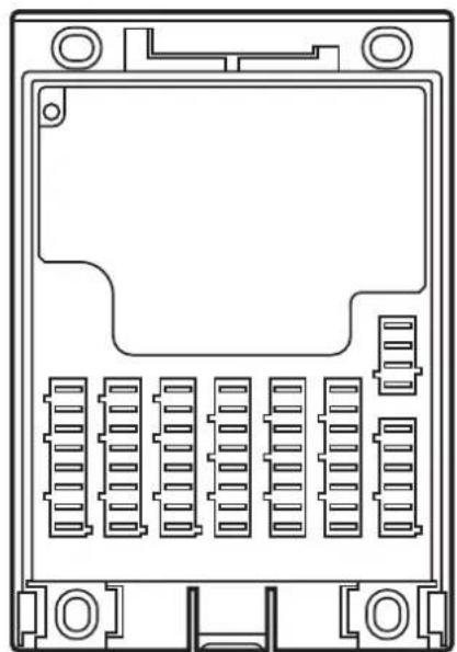
natural_image
Technical line drawing of an electronic device rear panel with multiple slots and mounting holes (no text or symbols)Contents
1 Preliminary note 4
1.1 Symbols used.... 4
1.2 Warning signs used 4
2 Safety instructions 5
2.1 General....5
2.2 Target group 5
2.3 Electrical connection 5
2.4 Tampering with the device 5
3 Functions and features 6
3.1 Overview of the common characteristics 6
3.2 Application example 6
3.3 Devices of the Basic series (examples) 7
4 Installation....8
4.1 General installation instructions 8
4.1.1 Protection....8
4.1.2 Mounting surface 8
4.2 Fastening 8
4.3 Cover and cable seal 10
4.3.1 Installation of the cable seal.... 10
4.3.2 Removal of the cable seal 10
4.3.3 Installation of the cover .....11
4.3.4 Removing the cover....11
5 Electrical connection.... 12
5.1 General electrical connection 12
5.2 Connection accessories 13
5.2.1 Example accessories 13
5.3 Frequency inputs 13
5.4 Fuses 13
6 Indicators 14
7 Set-up.... 15
7.1 Programming 15
7.2 Required documentation 15
7.3 Required hardware.... 15
8 Technical data. 16
8.1 CR0401 16
8.2 CR0403 21
8.3 CR0411 27
9 Maintenance, repair and disposal. 33
9.1 Maintenance.... 33
9.2 Cleaning the housing surface.... 33
9.3 Repair.... 33
9.4 Disposal 33
10 Approvals/standards.... 33
UK
1 Preliminary note
This document applies to devices of the type "BasicController" (art. no.: CR0401, CR0403) and "BasicController plus" (art. no.: CR0411).
These instructions are an integral part of the device.
This document is intended for specialists. These specialists are people who are qualified by their appropriate training and their experience to see risks and to avoid possible hazards that may be caused during operation or maintenance of the device. The document contains information about the correct handling of the device.
Read this document before use to familiarise yourself with operating conditions, installation and operation. Keep this document during the entire duration of use of the device.
Adhere to the safety instructions.
1.1 Symbols used
▶ Instruction
Reaction, result
[...] Designation of keys, buttons or indications
→ Cross-reference

Important note
Non-compliance can result in malfunction or interference.

Information
Supplementary note
1.2 Warning signs used
WARNING
Warning of serious personal injury.
Death or serious irreversible injuries may result.
CAUTION
Warning of personal injury.
Slight reversible injuries may result.
NOTE
Warning of damage to property.
2 Safety instructions
2.1 General
These instructions contain texts and figures concerning the correct handling of the device and must be read before installation or use.
Observe the operating instructions. Non-observance of the instructions, operation which is not in accordance with use as prescribed below, wrong installation or incorrect handling can seriously affect the safety of operators and machinery.
2.2 Target group
These instructions are intended for authorised persons according to the EMC and low-voltage directives. The device must only be installed, connected and put into operation by a qualified electrician.
2.3 Electrical connection
Disconnect the device externally before handling it. If necessary, also disconnect any independently supplied output load circuits.
If the device is not supplied by the mobile on-board system (12/24 V battery operation), it must be ensured that the external voltage is generated and supplied according to the criteria for safety extra-low voltage (SELV) as this voltage is supplied without further measures to the connected controller, the sensors and the actuators.
The wiring of all signals in connection with the SELV circuit of the device must also comply with the SELV criteria (safety extra-low voltage, safe electrical isolation from other electric circuits).
If the supplied SELV voltage is externally grounded (SELV becomes PELV), the responsibility lies with the user and the respective national installation regulations must be complied with. All statements in this document refer to the device the SELV voltage of which is not grounded.
The connections may only be supplied with the signals indicated in the technical data and/or on the device label and only the approved accessories of ifm electronic gmbh may be connected.
2.4 Tampering with the device
In case of malfunctions or uncertainties please contact the manufacturer. Any tampering with the device can seriously affect the safety of operators and machinery. This is not permitted and leads to the exclusion of any liability and warranty claims.
3 Functions and features
The freely programmable controllers of the "BasicController" and "BasicController ^plus " series are rated for use under difficult conditions (e.g. extended temperature range, strong vibration, intensive EMC interference). They are suitable for direct installation in mobile vehicles.
By means of the application software the user can configure the inputs and outputs to adapt to the respective application. The controllers can be used as CAN controller, CANopen master or intelligent I/O module. ( 8 Technical data).
Application-specific extensions and adaptations are possible in conjunction with additional products of the modular Basic series.

WARNING
The "BasicController" and "BasicController plus" series are not approved for safety tasks in the field of safety of persons.
NOTE
"BasicController" and "BasicController ^plus " are intended for installation in vehicle bodies, not in engines.
3.1 Overview of the common characteristics
• Freely programmable to IEC 61131-3
- 2 CAN interfaces (incl. interface for BasicDisplay CR0451 or CR0452)
- Configurable inputs/outputs
- Protection IP 20 (with cover and cable seal IP 54)
- Status LED
3.2 Application example
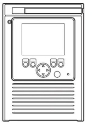
natural_image
Line drawing of a front-mounted electronic device with control panel and ventilation slots (no text or symbols)Use with cover and BasicDisplay
3.3 Devices of the Basic series (examples)
-
BasicDisplay (art. no.: CR0451)
programmable 2.8 inch colour display with graphic capabilities
5 freely programmable backlit function keys
1 rocker switch for cursor function -
BasicDisplay XL (art. no.: CR0452)
programmable 4.3 inch colour display with graphic capabilities
6 freely programmable backlit function keys
1 rocker switch for cursor function
- BasicRelay (art. no.: CR0421) freely wirable relay and fuse carrier for 6 automotive relays and 10 automotive fuses
- Cover (art. no.: EC0401)
- Cover with built-in display recess (art. no.: EC0402)
incl. cable seal to obtain protection rating IP 54
For information about the available Basic products see:
www.ifm.com → Products → Control systems
or directly
www.ifm.com → Data sheet search → e.g. CR0451
4 Installation
4.1 General installation instructions
4.1.1 Protection
The achievable protection rating of the device depends on the accessories used and the mounting position.
| Protection Accessories Installation position Art. no. | |||
| IP 20 – freely selectable – | |||
| IP 54 cover with | cable seal cable connection from the | bottom | e.g. EC0401 |
4.1.2 Mounting surface
NOTE
The housing must not be exposed to any torsional forces or mechanical stress.
▶ Mount the device on a flat surface.
▶ Use compensating elements if there is no flat mounting surface available.
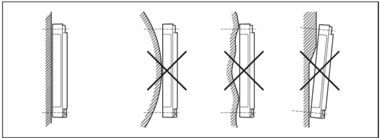
natural_image
Four technical diagrams showing mechanical assembly or assembly states with crosshair marks, no text or symbols present.Mounting surface
4.2 Fastening
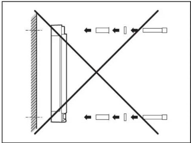
▶ Insert the enclosed tubular rivets from the back of the module in the 4 fixing holes.
▶ Fix the module using 4 washers and M4 screws.
Tighten the screws alternately crosswise.
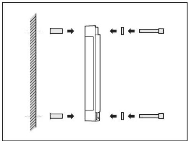
natural_image
Pure mechanical assembly diagram showing a vertical wall, rectangular components, and directional arrows without any text or symbolsUse of the tubular rivets
natural_image
Pure mechanical diagram showing a vertical component with diagonal lines and directional arrows, no text or symbols present.Tightening torque: 1.5 Nm
Hole dimensions ( 8 Technical data)
| Screws to be used (examples): Standard | |
| Cylinder screws with hexagon socket (M4 x L) DIN 912 | |
| Cylinder screws with hexagon socket and low head (M4 x L) DIN 7984 |
4.3 Cover and cable seal
NOTE
Protection IP 54 can only be guaranteed if the cover is used together with the cable seal.
NOTE
When a cover is installed, the device temperature can increase.
4.3.1 Installation of the cable seal
▶ Insert the cable seal into the locator from below.
The locking of the cable seal audibly clips into place.
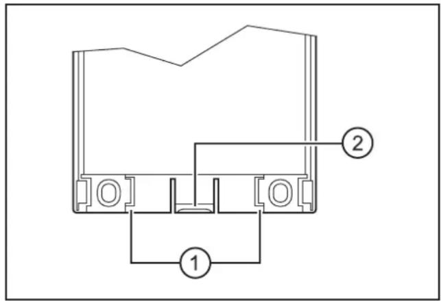
- Locator for cable seal
- Locking
natural_image
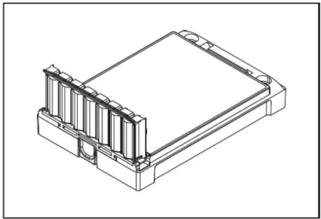
Technical line drawing of a rectangular electronic component with internal channels and mounting holes (no text or symbols)Mounted cable seal

The cable seal cannot be used as strain relief of the cables.
(→ 5.1 General electrical connection)
4.3.2 Removal of the cable seal
▶ Press the locking at the bottom of the device and remove the cable seal from the device by pulling downwards.
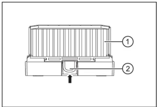
Bottom of the device
- Cable seal
- Locking
4.3.3 Installation of the cover
The covers of the Basic series feature a single-lever locking. Installation is done without tools.
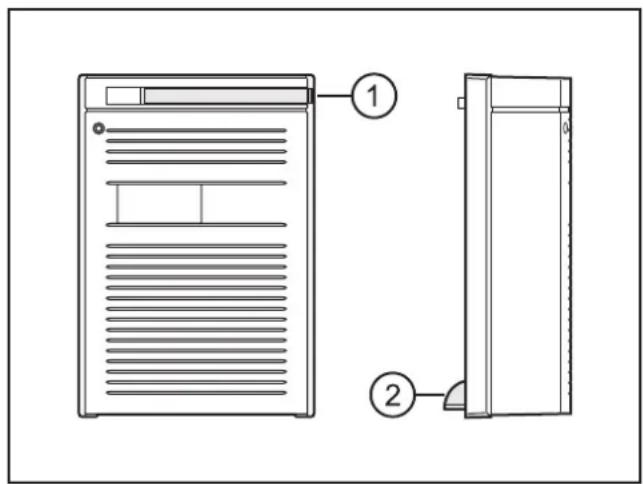
1: locking lever
2: cover guides
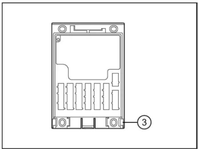
natural_image
Technical line drawing of a device casing with internal compartments and mounting holes (no text or symbols)3: insertion slots for cover guides
▶ Pull out the locking lever and rotate it towards you.
▶ Place the cover diagonally onto the device.
Insert the 2 cover guides, found at the bottom of the cover, into the slots.
▶ Close the cover onto the lower part.
The 2 guides and slots provide a pivot point.
▶ Move the locking lever back into its initial position.
The cover is locked.
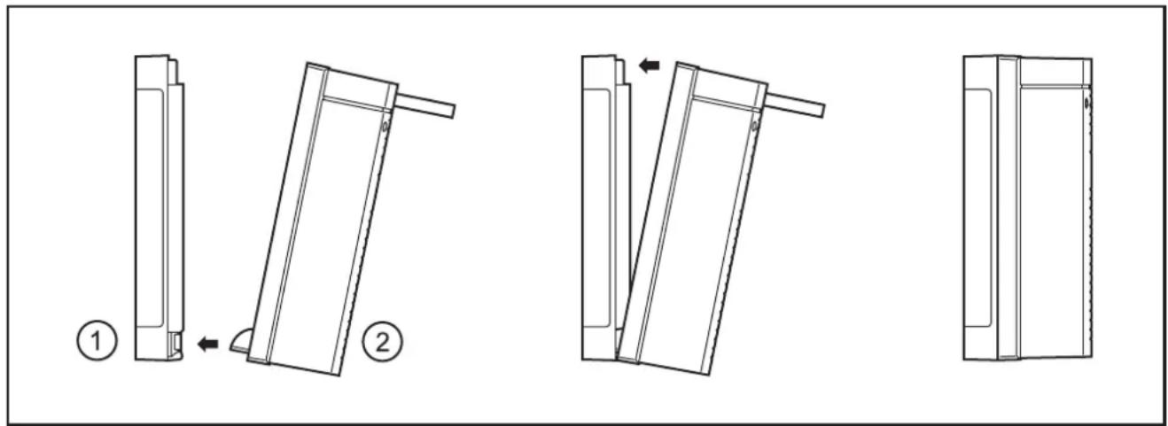
1: BasicController
2: cover
4.3.4 Removing the cover
▶ Pull out the locking lever and rotate it towards you.
The cover is unlocked and can be removed.
5 Electrical connection
5.1 General electrical connection
The supply cables, CAN interfaces and input/outputs are connected via 6.3 x 0.8 mm blade male terminals on the front of the device.
Wiring ( 8 Technical data)
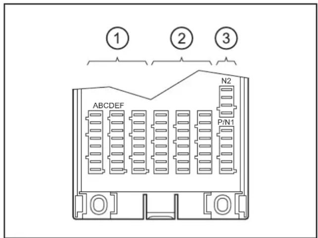
Connector area (here e.g. CR0403)
1: Inputs
2: Outputs
3: Supply and CAN interfaces
| Connector | Connection CR0401 | CR0403 CR0411 N | Number of | poles | |
| A Inputs IN0...3 IN0...3 IN0...3 8 | |||||
| B IN4...7 IN4...7 | |||||
| C IN8...11 | IN8...11 | - | |||
| D | Outputs | - | OUT0...3 | OUT0...3 | |
| E OUT0...3 | OUT4...7 | OUT4...7 | |||
| F | OUT4...7 | OUT8...11 | - | ||
| P/N1 | CAN interface 1 and supply | 6 | |||
| N2 | CAN interface 2 (e.g. for BasicDisplay CR0451 or CR0452) | 4 | |||
- = not connected
NOTE
Wrong connection may cause damage to the device.
▶ Observe the safety instructions ( 2.3 Electrical connection).
▶ Basically all supply and signal cables must be laid separately.
▶ Lay supply and signal cables away from the device using the shortest possible route.
▶ All connected cables must be provided with a strain relief at least 100 mm behind the cable entry.
▶ Protect unused terminals with unpopulated sockets if no cover is used.
5.2 Connection accessories
You can find more information about the available accessories at: www.ifm.com → Data sheet search → e.g. CR0401 → Accessories
5.2.1 Example accessories
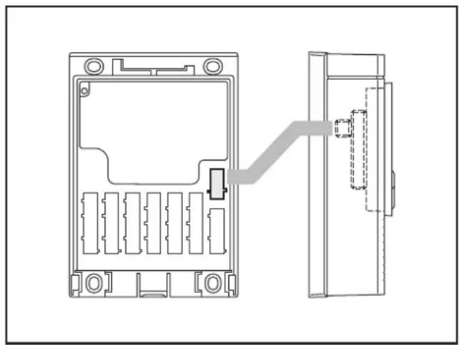
natural_image
Technical line drawing of a device housing with internal compartments and a separate panel (no text or symbols)Accessories and example connection
BasicDisplay CR0451
cover with EC0402 built-in display recess
EC0452 connection cable
5.3 Frequency inputs
▶ Operate frequency inputs with screened cables, so that useful signals are not affected by external interference.
5.4 Fuses
The individual electric circuits must be protected in order to protect the whole system.
| Description Potential Connector: pin Fuse | ||||
| VBB_S | Supply sensors/module 8...32 V DC P/N1: 1 ≤ 2 A T | |||
| VBB_1 | Supply outputsCR0401: OUT0...3CR0403: OUT0...7CR0411: OUT0...3 | 8...32 V DC P/N1: 2 | 15 A | |
| VBB_2 | Supply outputsCR0401: OUT4...7CR0403: OUT8...11CR0411: OUT4...7 | 8...32 V DC P/N1: 3 | 15 A | |
6 Indicators
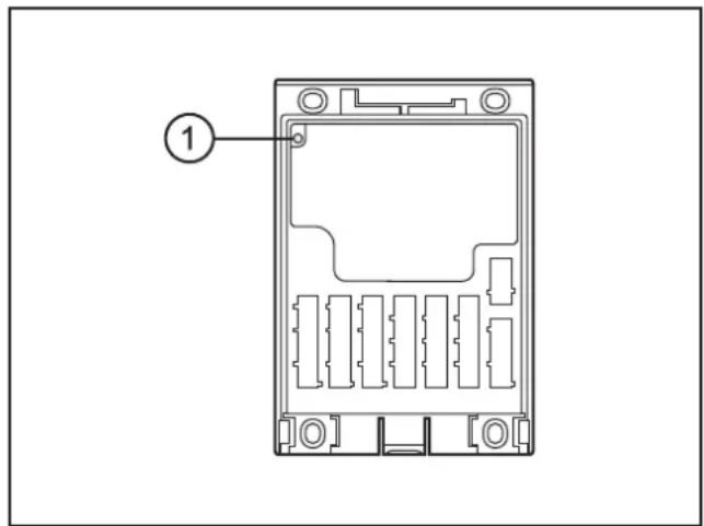
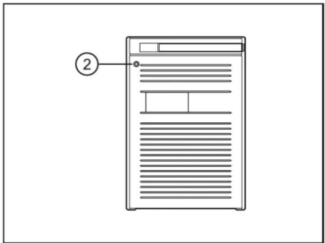
1: Status LED 2: LED lighting in the cover (e.g. EC0401)
Operating states ( 8 Technical data)
7 Set-up
7.1 Programming
The user can easily create the application software by means of the IEC 61131-3 compliant programming system CODESYS 2.3.

WARNING
The user is responsible for the safe function of the application programs which he created himself. If necessary, he must additionally carry out an approval test by corresponding supervisory and test organisations according to the national regulations.
7.2 Required documentation
In addition to the CODESYS programming system, the following documents are required for programming and set-up of the device:
- Programming manual CODESYS V2.3
(alternatively as online help) - BasicController system manual
(alternatively as online help)
The manuals can be downloaded from the internet:
www.ifm.com → Data sheet search → e.g. CR0401 → Additional data
CODESYS and BasicController online help
www.ifm.com → Service → Download → Control systems*
*) Download area with registration
7.3 Required hardware
A CAN interface for the connection to a PC or a notebook is required to load the application program to the device.
Example:
• CAN/RS232 USB interface CANfox (art. no.: EC2112)
- Adapter cable for CANfox (art. no.: EC2113)
You can find more information about the available accessories at:
www.ifm.com → Data sheet search → CR0451 → Accessories
or directly
www.ifm.com → Data sheet search → EC2112
8 Technical data
8.1 CR0401
CR0401
Mobile controller
BasicController
12 inputs
8 outputs
2 CAN interfaces
Programming
to IEC 61131-3
8...32 V DC
C€
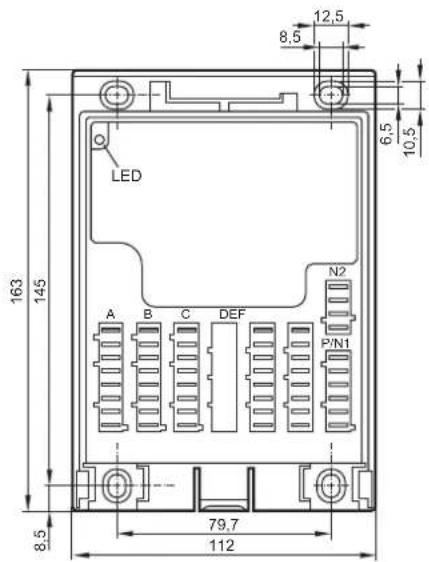
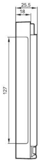

| Technical data |
| Mechanical data |
| Housing |
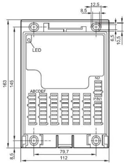
| Dimensions (H x W x D) without cover with EC0401 cover with EC0402 cover and BasicDisplay CR0451 |
| Installation |
| Connection |
| Inputs Outputs Operating voltage, CAN bus |
| Protection rating |
| Operating/storage temperature |
| Weight |
| Electrical data |
| Operating voltage |
| Current consumption |
| Overvoltage Undervoltage detection Undervoltage shutdown |
| Processor |
| Memory (total) |
| Memory allocation |
| Device monitoring |
| Modular control systemUsable as CANopen controller or intelligent I/O module |
| plastic housing (black) |
| 163 x 112 x 25.5 mm163 x 112 x 68 mm |
| 163 x 112 x 73.4 mm |
| fixing by means of 4 M4 screws to DIN 912 or DIN 7984 and 4 tubular rivets to DIN 7340 (tubular rivets are supplied) |
| AMP blade male terminals 6.3 mm, to be clipped into place and thus vibration-resistant, protected against reverse polaritycontacts AMP timer, CuZn pre-tin-platedcore cross-section 0.5...2.5 mm^2 |
| 3 x 8-pole2 x 8-pole1 x 6-pole, 1 x 4-pole |
| IP 20 (with cover and cable seal IP 54) |
| -40...85°C / -40...85°C |
| 0.30 kg |
| 8...32 V DC |
| 45 mA (at 24 V DC) |
| 36 V for t ≤ 10 sat U_B ≤ 7.8 Vat U_B ≤ 7.0 V |
| Freescale PowerPC, 50 MHz |
| 208 Kbytes RAM / 1536 Kbytes Flash / 1 Kbyte FRAM |
| see BasicController system manualwww.ifm.com → data sheet search → e.g. CR0401 → Additional data |
| undervoltage monitoringwatchdog functionchecksum test for program and systemexcess temperature monitoring |
CR0401 Technical data
CAN interfaces 1/2
Baud rate
Communication profi le
Software/programming
Programming system CODESYS version
Inputs 12 (confi gurable),
Configurations
Outputs 8 (confi gurable),
Configurations
Status LED two-colour LED (red/green)
Operating states (preset)
CAN interface 2.0 A/B, ISO 11898
20 kBit/s...1 MBit/s (default CAN1: 250 kBit/s, CAN2: 250 kBit/s)
CANopen, CiA DS 301 version 4, CiA DS 401 version 1.4
or SAE J 1939 or free protocol
Number Version
| 4 digital for positive / negative sensor signals analogue (0...10/32 V DC, 0..20 mA, ratiometric) frequency (≤ 30 kHz) | B_L/B_H AFRQ |
| 4 digital for positive sensor signals resistance measurement (0,016...3.6 kΩ) | B_L |
| 4 digital for positive sensor signals B | L |
positive sensor signals have diagnostic capabilities
Number Version
| 2 positive | switching (high side)PWM output (20...250 Hz), 2 A, diagnosis | BH PWM |
| 4 positive | switching (high side)PWM output (20...250 Hz), 1 A | BH PWM |
| 2 positive | switching (high side)PWM output (20...250 Hz), 4 A, diagnosis | BH PWM |
Colour Status Description
| – permanently | off no operating | voltage |
| orange | 1 x on | initialisation or reset checks |
| green | 5 Hz no operating | system loaded |
| 2 Hz application is running (RUN) | ||
| permanently on | application stopped (STOP) | |
| red | 10 Hz | application stopped (STOP with error) |
| 5 Hz application stopped due to undervoltage | ||
| permanently on | system fault (fatal error) | |
CR0401 Technical data
Characteristics of the inputs
Analogue inputs (A)
Connection A: 02, 03, 06, 07
IN0...IN3
can be configured as:
Digital input (B _L )
Connection B: 02, 03, 06, 07
IN4...IN7
can be configured as...
| Voltage inputs | |
| Input voltage 0...10 V or 0...32 V | |
| Resolution 12 bits | |
| Accuracy ± 1% FS | |
| Input resistance 65.6 kΩ (0...10 V), 50.7 kΩ (0...32 V) | |
| Input frequency ≤ 500 Hz | |
| Current inputs, with diagnostic capability | |
| Input current 0...20 mA | |
| Resolution 12 bits | |
| Accuracy ± 1% FS | |
| Input resistance 400 Ω | |
| Input frequency ≤ 500 Hz | |
| At a current of >23 mA the input is switched to the voltage input! | |
| Voltage inputs, 0...32 V, ratiometric | |
| Function (U) | IN + UB) x 1000 %o |
| Value range 0...1000 %o | |
| Input resistance 50.7 kΩ | |
| Binary voltage inputs for positive sensor signals | |
| Switch-on level >0.7 U | B |
| Switch-off level < 0.3 U | B |
| Input resistance 3.2 kΩ | |
| Input frequency 50 Hz | |
| Diagnosis wire break | >0.95 UB |
| Diagnosis short circuit | < 1 V |
| Binary voltage inputs for negative sensor signals | |
| Switch-on level >0.7 UB | |
| Switch-off level < 0.3 UB | |
| Input resistance 3.2 kΩ | |
| Input frequency 50 Hz | |
| Frequency inputs | |
| Input resistance 3.2 kΩ | |
| Input frequency ≤ 30 kHz | |
| Switch-on level >0.35...0.48 U | B |
| Switch-off level < 0.29 U | B |
| Binary voltage inputs for positive sensor signals | |
| Switch-on level >0.7 U | B |
| Switch-off level < 0.3 U | B |
| Input resistance 3.2 kΩ | |
| Input frequency 50 Hz | |
| Diagnosis wire break | >0.95 UB |
| Diagnosis short circuit | <1 V |
| Resistor input | |
| Measuring range | 16...3.6 kΩ |
| Accuracy ± 3 % | |
CR0401 Technical data
| Digital input (BL) |
| Connection C: 02, 03, 06, 07 |
| IN8...IN11 |
| can be configured as... |
Characteristics of the outputs
| Digital outputs (BH, PWM) |
| Connection F: 01, 03, |
| OUT4...OUT5 |
| Digital outputs (BH, PWM) |
| Connection E: 01, 03, 05, 07 |
| OUT0...OUT3 |
| Digital outputs (BH, PWM) |
| Connection F: 05, 07 |
| OUT6...OUT7 |
Free wheel diodes
| Overload protection (valid for all outputs) |
| Short-circuit strength (valid for all inputs and outputs) |
| Max. total current of the output supplies VBB1/VBB2(Continuous current load) |
| • Binary voltage inputs for positive sensor signals | |
| Switch-on level > 0.7 U | B |
| Switch-off level < 0.3 U | B |
| Input resistance 3.2 kΩ | |
| Input frequency 50 Hz | |
| Diagnosis wire break > 0.95 U | B |
| Diagnosis short circuit < 1 V | |
| Semiconductor outputs, positive switching (high side), short-circuit and overload protected. Diagnosis via voltage feedback, pullup resistance can be deactivated (wire break/ short circuit) | |
| Switching voltage 8...32 V DC | |
| Switching current ≤ 2A | |
| PWM outputs | |
| Output frequency 20...250 Hz | |
| Pulse/pause ratio 1...1000 %o | |
| Switching current ≤ 2A | |
| If only one output of the output pair is active, the switching current is ≤ 2.5 A. | |
| Max. switch-on current ≤ 11 A | |
| Semiconductor outputs, positive switching (high side), short-circuit and overload protected | |
| Switching voltage 8...32 V DC | |
| Switching current ≤ 1 A | |
| PWM outputs | |
| Output frequency 20...250 Hz | |
| Pulse/pause ratio 1...1000 %o | |
| Switching current ≤ 1 A | |
| Max. switch-on current ≤ 11 A | |
| Semiconductor outputs, positive switching (high side), short-circuit and overload protected. Diagnosis via voltage feedback, pullup resistance can be deactivated (wire break/ short circuit) | |
| Switching voltage 8...32 V DC | |
| Switching current ≤ 4 A | |
| PWM outputs | |
| Output frequency 20...250 Hz | |
| Pulse/pause ratio 1...1000 ‰ | |
| Switching current ≤ 4 A | |
| Max. switch-on current ≤ 30 A | |
free wheel diodes for the deactivation of inductive loads are integrated
| ≤ 5 minutes (at 100% overload) |
| ≤ 5 minutes (contact +VBB with GND) |
| permanently ≤ 50 % of the nominal current |
| CR0401 Technical data | ||||||||
| Test standards and regulations | ||||||||
| CE marking EN 61000-6-2 Electromagnetic compatibility (EMC) Noise immunity | ||||||||
| E1 marking UN/ECE-R10 Emission standard Immunity with 100 V/m | ||||||||
| Electrical tests ISO 7637-2 Pulse 1, severity level: IV; function state C Pulse 2a, severity level: IV; function state A Pulse 2b, severity level: IV; function state C Pulse 3a, severity level: IV; function state A Pulse 3b, severity level: IV; function state A Pulse 4, severity level: IV; function state A Pulse 5, severity level: III; function state C (data valid for the 24 V system) Pulse 4, severity level: III; function state C (data valid for the 12 V system) | ||||||||
| Climatic tests EN 60068-2-30 Damp heat, cyclic Upper temperature 55°C, number of cycles: 6 | ||||||||
| Mechanical tests ISO 16750-3 | Test VII; Vibration, random Mounting location: vehicle body | |||||||
| EN 60068-2-6 Vibration, sinusoidal 10...500 Hz; 0.72 mm/10 g; 10 cycles/axis | ||||||||
| ISO 16750-3 Bumps 30 g/6 ms; 24,000 shocks | ||||||||
| Note | The EC declaration of conformity and approvals can be found at: www.ifm.com → data sheet search → CR0401 → More information | |||||||
| Wiring | ||||||||
| A | B | C | D | E | F | N2 | P/N1 | |
| 8 poles | 4 poles | 6 poles | ||||||
| VBBsIN0IN1GNDGNDIN2IN3VBBs | VBBsIN4IN5GNDGNDIN6IN7VBBs | VBBsIN8IN9GNDGNDIN10IN11VBBs | OUT0GNDOUT1GNDOUT2GNDOUT3GND | OUT4GNDOUT5GNDOUT6GNDOUT7GND | VBBsGNDCAN2_HCAN2_L | VBBsVBB1VBB2GNDCAN1_HCAN1_L | ||
| D = not used | ||||||||
| Abbreviations | A = analogue BH = binary high side BL = binary low side FRQ = frequency/pulse inputs PWM= pulse width modulation VBBs= supply sensors/module VBB1= supply OUT 0...3 VBB2= supply OUT 4...7 | |||||||
ifm electronic gmbh • Friedrichstraße 1 • 45128 Essen
We reserve the right to make technical alterations without prior notice! 24.10.2014CR0401 / page 5
8.2 CR0403
CR0403
Mobile controller
BasicController
12 inputs
12 outputs
2 CAN interfaces
Programming
to IEC 61131-3
8...32 V DC
CE
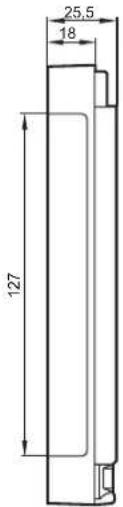
E1
Technical data
Mechanical data
| Housing |
| Dimensions (H x W x D) |
| without cover |
| with EC0401 cover |
| with EC0402 cover and BasicDisplay |
| CR0451 |
Installation
Connection
| Inputs |
| Outputs |
| Operating voltage, CAN bus |
| Protection rating |
| Operating/storage temperature |
| Weight |
Electrical data
| Operating voltage |
| Current consumption |
| Overvoltage |
| Undervoltage detection |
| Undervoltage shutdown |
Processor
| Memory (total) |
| Memory allocation |
| Device monitoring |
Modular control system
Usable as CANopen master or intelligent I/O module
| plastic housing (black) |
| 163 x 112 x 25.5 mm163 x 112 x 68 mm |
| 163 x 112 x 73.4 mm |
| fixing by means of 4 M4 screws to DIN 912 or DIN 7984 and 4 tubular rivets to DIN 7340 (tubular rivets are supplied) |
| AMP blade male terminals 6.3 mm, to be clipped into place and thus vibration-resistant, protected against reverse polaritycontacts AMP timer, CuZn pre-tin-platedcore cross-section 0.5...2.5 mm^2 |
| 3 x 8-pole3 x 8-pole1 x 6-pole, 1 x 4-pole |
| IP 20 (with cover and cable seal IP 54) |
| -40...85°C / -40...85°C |
| 0.30 kg |
| 8...32 V DC |
| 45 mA (at 24 V DC) |
| 36 V for t ≤ 10 sat U_B ≤ 7.8 Vat U_B ≤ 7.0 V |
| Freescale PowerPC, 50 MHz |
| 592 Kbytes RAM / 1536 Kbytes Flash / 1 Kbyte FRAM |
| see BasicController system manualwww.ifm.com → data sheet search → e.g. CR0403 → Additional data |
| undervoltage monitoringwatchdog functionchecksum test for program and systemexcess temperature monitoring |
ifm electronic gmbh • Friedrichstraße 1 • 45128 Essen
We reserve the right to make technical alterations without prior notice! 24.10.2014CR0403 / page 1
CR0403 Technical data
CAN interfaces 1/2
Baud rate
Communication profi le
Software/programming
Programming system CODESYS version
Inputs 12 (confi gurable)
Configurations
Outputs 12 (confi gurable)
Configurations
Status LED two-colour LED (red/green)
Operating states (preset)
CAN interface 2.0 A/B, ISO 11898
20 kBit/s...1 MBit/s (Default CAN1: 250 kBit/s, CAN2: 250 kBit/s)
CANopen, CiA DS 301 version 4, CiA DS 401 version 1.4
or SAE J 1939 or free protocol
Number Version
| 4 digital for positive / negative sensor signals analogue (0...10/32 V DC, 0..20 mA, ratiometric) frequency (≤ 30 kHz) | B_L/B_H AFRQ |
| 4 digital for positive sensor signals resistance measurement (0,016...3.6 kΩ) | B_L |
| 4 digital for positive sensor signals B | L |
positive sensor signals have diagnostic capabilities
Number Version
| 2 positive | switching (high side)PWM output (20...250 Hz), 2A,current-controlled 0.02...2 A, diagnosis | BHPWMPWM-I |
| 4 positive | switching (high side)PWM output (20...250 Hz), 2 A, diagnosis | BHPWM |
| 4 positive | switching (high side)PWM output (20...250 Hz), 1 A | BHPWM |
| 2 positive | switching (high side)PWM output (20...250 Hz), 4 A, diagnosis | BHPWM |
Colour Status Description
| – permanently | off no operating | voltage |
| orange | 1 x on | initialisation or reset checks |
| green | 5 Hz no operating | system loaded |
| 2 Hz application is running (RUN) | ||
| permanently on | application stopped (STOP) | |
| red | 10 Hz | application stopped (STOP with error) |
| 5 Hz application stopped due to undervoltage | ||
| permanently on | system fault (fatal error) | |
CR0403 Technical data
Characteristics of the inputs
Analogue inputs (A)
Connection A: 02, 03, 06, 07
IN0...IN3
can be configured as:
Digital input (B _L )
Connection B: 02, 03, 06, 07
IN4...IN7
can be configured as...
| Voltage inputs | |
| Input voltage 0...10 V or 0...32 V | |
| Resolution 12 bits | |
| Accuracy ± 1% FS | |
| Input resistance 65.6 kΩ (0...10 V), 50.7 kΩ (0...32 V) | |
| Input frequency ≤ 500 Hz | |
| Current inputs, with diagnostic capability | |
| Input current 0...20 mA | |
| Resolution 12 bits | |
| Accuracy ± 1% FS | |
| Input resistance 400 Ω | |
| Input frequency ≤ 500 Hz | |
| At a current of >23 mA the input is switched to the voltage input! | |
| Voltage inputs, 0...32 V, ratiometric | |
| Function (U) | IN + UB) x 1000 %o |
| Value range 0...1000 %o | |
| Input resistance 50.7 kΩ | |
| Binary voltage inputs for positive sensor signals | |
| Switch-on level >0.7 U | B |
| Switch-off level < 0.3 U | B |
| Input resistance 3.2 kΩ | |
| Input frequency 50 Hz | |
| Diagnosis wire break | >0.95 UB |
| Diagnosis short circuit | < 1 V |
| Binary voltage inputs for negative sensor signals | |
| Switch-on level >0.7 UB | |
| Switch-off level < 0.3 UB | |
| Input resistance 3.2 kΩ | |
| Input frequency 50 Hz | |
| Frequency inputs | |
| Input resistance 3.2 kΩ | |
| Input frequency < 30 kHz | |
| Switch-on level >0.35...0.48 U | B |
| Switch-off level < 0.29 U | B |
| Binary voltage inputs for positive sensor signals | |
| Switch-on level >0.7 U | B |
| Switch-off level < 0.3 U | B |
| Input resistance 3.2 kΩ | |
| Input frequency 50 Hz | |
| Diagnosis wire break | >0.95 UB |
| Diagnosis short circuit | <1 V |
| Resistor input | |
| Measuring range | 16...3.6 kΩ |
| Accuracy ± 3 % | |
CR0403 Technical data
Digital input (B _L )
Connection C: 02, 03, 06, 07
IN8...IN11
can be configured as...
Characteristics of the outputs
Digital outputs (BH, PWM, PWM-I)
Connection D: 01, 03
OUT0...OUT1
Digital outputs (B _H , PWM)
Connection D: 05, 07
OUT2...OUT3
Connection F: 01, 03,
OUT8...OUT9
| • Binary voltage inputs for positive sensor signals | |
| Switch-on level > 0.7 U | B |
| Switch-off level < 0.3 U | B |
| Input resistance 3.2 kΩ | |
| Input frequency 50 Hz | |
| Diagnosis wire break > 0.95 U | B |
| Diagnosis short circuit < 1 V | |
| Semiconductor outputs, positive switching (high side), short-circuit and overload protectedDiagnosis via current feedback (wire break / overload)Diagnosis via voltage feedback, pullup resistance can be deactivated (wire break/ short circuit) | |
| Switching voltage 8...32 V DC | |
| Switching current ≤ 2A | |
| Load resistance ≥ 6 Ω (at 12 V DC)≥ 12 Ω (at 24 V DC) | |
| PWM outputs | |
| Output frequency 20...250 Hz | |
| Pulse/pause ratio 1...1000 %o | |
| Switching current ≤ 2A | |
| Current-controlled output | |
| Output frequency 20...250 Hz | |
| Control range 0.02...2 A | |
| Setting resolution 1 mA | |
| Control resolution | 2 mA |
If only one output is active, the switching current is ≤ 2.5 A.
| Max. switch-on current | ≤ 11 A |
| Semiconductor outputs, positive switching (high side), short-circuit and overload protectedDiagnosis via voltage feedback, pullup resistance can be deactivated (wire break/ short circuit) | |
| Switching voltage 8...32 V DC | |
| Switching current ≤ 2A | |
| PWM outputs | |
| Output frequency 20...250 Hz | |
| Pulse/pause ratio 1...1000 ‰ | |
| Switching current ≤ 2 A | |
If only one output of the output pair is active, the switching current is ≤ 2.5 A.
| Max. switch-on current | ≤ 11 A |
CR0403 Technical data
| Digital outputs (BH) |
| Connection E: 01, 03, 05, 07 |
| OUT4...OUT7 |
| Digital outputs (BH, PWM) |
| Connection F: 05, 07 |
| OUT10...OUT11 |
| Semiconductor outputs, positive switching (high side), short-circuit and overload protected | |
| Switching voltage 8...32 V DC | |
| Switching current ≤ 1 A | |
| PWM outputs | |
| Output frequency 20...250 Hz | |
| Pulse/pause ratio 1...1000 %o | |
| Switching current ≤ 1 A | |
| Max. switch-on current ≤ 11 A | |
| Semiconductor outputs, positive switching (high side), short-circuit and overload protectedDiagnosis via voltage feedback, pullup resistance can be deactivated (wire break/ short circuit) | |
| Switching voltage 8...32 V DC | |
| Switching current ≤ 4 A | |
| PWM outputs | |
| Output frequency 20...250 Hz | |
| Pulse/pause ratio 1...1000 %o | |
| Switching current ≤ 4 A | |
| Max. switch-on current ≤ 30 A | |
| Free wheel diodes free wheel diodes for |
| Overload protection(valid for all outputs) |
| Short-circuit strength(valid for all inputs and outputs) |
| Max. total current of the output supplies VBB_1/VBB_2 (continuous current load) |
the deactivation of inductive loads are integrated
| ≤ 5 minutes (at 100% overload) |
| ≤ 5 minutes (contact +VBB with GND) |
| permanently ≤ 50 % of the nominal current |
| CR0403 Technical data | ||||||||
| Test standards and regulations | ||||||||
| CE marking EN 61000-6-2 Electromagnetic compatibility (EMC) Noise immunity | ||||||||
| E1 marking UN/ECE-R10 Emission standard Immunity with 100 V/m | ||||||||
| Electrical tests ISO 7637-2 Pulse 1, severity level: IV; function state C Pulse 2a, severity level: IV; function state A Pulse 2b, severity level: IV; function state C Pulse 3a, severity level: IV; function state A Pulse 3b, severity level: IV; function state A Pulse 4, severity level: IV; function state A Pulse 5, severity level: III; function state C (data valid for the 24 V system) Pulse 4, severity level: III; function state C (data valid for the 12 V system) | ||||||||
| Climatic tests EN 60068-2-30 Damp heat, cyclic Upper temperature 55°C, number of cycles: 6 | ||||||||
| Mechanical tests ISO 16750-3 Test VII; vibration, random Mounting location: vehicle body | ||||||||
| Note The EC declaration of conformity and approvals can be found at: www.ifm.com → data sheet search → CR0403 → More information | ||||||||
| Wiring | ||||||||
| A | B | C | D | E | F | N2 | P/N1 | |
| 8 poles | 4 poles | 6 poles | ||||||
| VBBsIN0IN1GNDGNDIN2IN3VBBs | VBBsIN4IN5GNDGNDIN6IN7VBBs | VBBsIN8IN9GNDGNDIN10IN11VBBs | OUT0GNDOUT1GNDOUT2GNDOUT3GND | OUT4GNDOUT5GNDOUT6GNDOUT7GND | OUT8GNDOUT9GNDOUT10GNDOUT11GND | VBBsGNDCAN2_HCAN2_L | VBBsVBB1VBB2GNDCAN1_HCAN1_L | |
| Abbreviations | A = analogue BH = binary high side BL = binary low side FRQ = frequency/pulse inputs PWM= pulse width modulation VBBs= supply sensors/module VBB1= supply OUT 0...7 VBB2= supply OUT 8...11 | |||||||
ifm electronic gmbh • Friedrichstraße 1 • 45128 Essen
We reserve the right to make technical alterations without prior notice! 24.10.2014CR0403 / page 6
8.3 CR0411
CR0411
Mobile controller
BasicController plus
8 inputs
8 outputs
2 CAN interfaces
Programming
to IEC 61131-3
8...32 V DC
CE
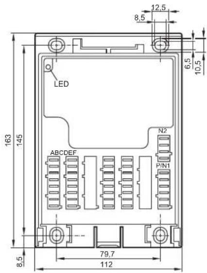
E1
Technical data
Mechanical data
| Housing |
| Dimensions (H x W x D) |
| without cover |
| with EC0401 cover |
| with EC0402 cover and BasicDisplay |
| CR0451 |
Installation
Connection
| Inputs |
| Outputs |
| Operating voltage, CAN bus |
| Protection |
| Operating/storage temperature |
| Weight |
Electrical data
| Operating voltage |
| Current consumption |
| Overvoltage |
| Undervoltage detection |
| Undervoltage shutdown |
Processor
| Memory (total) |
| Memory allocation |
| Device monitoring |
Modular control system
Usable as CANopen master or intelligent I/O module
| plastic housing (black) |
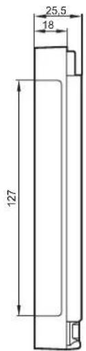
| 163 x 112 x 25.5 mm163 x 112 x 68 mm |
| 163 x 112 x 73.4 mm |
| fixing by means of 4 M4 screws to DIN 912 or DIN 7984 and 4 tubular rivets to DIN 7340 (tubular rivets are supplied) |
| AMP blade male terminals 6.3 mm, to be clipped into place and thus vibration-resistant, protected against reverse polaritycontacts AMP timer, CuZn pre-tin-platedcore cross-section 0.5...2.5 mm^2 |
| 2 x 8-pole2 x 8-pole1 x 6-pole, 1 x 4-pole |
| IP 20 (with cover and cable seal IP 54) |
| -40...85°C / -40...85°C |
| 0.30 kg |
| 8...32 V DC |
| 45 mA (at 24 V DC) |
| 36 V for t ≤ 10 sif U_B ≤ 7.8 Vif U_B ≤ 7.0 V |
| Freescale PowerPC, 50 MHz |
| 592 Kbytes RAM / 1536 Kbytes Flash / 1 Kbyte FRAM |
| see BasicController ^plus system manualwww.ifm.com → Data sheet search → e.g. CR0411 → Additional data |
| Undervoltage monitoringWatchdog functionChecksum test for program and systemExcess temperature monitoring |
ifm electronic gmbh • Friedrichstraße 1 • 45128 Essen
We reserve the right to make technical alterations without prior notice! 24.10.2014CR0411 / page 1
CR0411 Technical data
| CAN interfaces 1/2 |
| Baud rate |
| Communication profi le |
Software/programming
| Programming system CODESYS version | 2.3 (IEC 61131-3) |
Inputs 8 (confi gurable)
| Configurations |
Outputs 8 (confi gurable)
| Configurations |
Status LED two-colour LED (red/green)
| Operating states (preset) |
Abbreviations
| Number Description | ||
| 4 digital for positive/negative sensor signals analogue (0...10/32 V DC, 0...20 mA, ratiometric) frequency (≤ 30 kHz) | BL/BH A FRQ | |
| 4 digital for positive sensor signals resistance measurement (0.016...30 kΩ) | BL R | |
| positive sensor signals have diagnostic capabilities | ||
| Number Description | ||
| 4 positive switching (high side) PWM output (20...250 Hz), 2.5 A, current-controlled, 0.02...2.5 A, diagnosis | BH PWM PWM-I | |
| 4 positive switching (high side) negative switching (low side), 4 A PWM output (20...250 Hz), 4 A, diagnosis current-controlled, 0.02...4 A, diagnosis H-bridge function | BH BL PWM PWM-I H bridge | |
| Colour Status Description | ||
| - permanently off no operating voltage | ||
| orange 1 x on initialisation or reset checks | ||
| green | 5 Hz no operating system loaded | |
| 2 Hz application running (RUN) | ||
| permanently on application stopped (STOP) | ||
| Red | 10 Hz | application stopped (STOP with error) |
| 5 Hz application stopped due to undervoltage | ||
| permanently on system error (fatal error) | ||
| A Analogue BH Binary high side BL Binary low side FRQ Frequency/pulse inputs H H-bridge function PWM Pulse width modulation PWM-I Pulse width modulation, current-controlled R Resistor input VBBs Supply sensors/module VBB1 supply OUT 0...3 VBB2 supply OUT 4...7 | ||
We reserve the right to make technical alterations without prior notice! 24.10.2014CR0411 / page 2
CR0411 Technical data
Input characteristics
Analogue inputs (A, B_L / B_H ,FRQ)
Connection A: 02, 03, 06, 07 IN0...IN3
can be configured as...
Digital/resistor inputs (BL, R)
Connection B: 02, 03, 06, 07 IN4...IN7
can be configured as...
| Voltage inputs | |
| Input voltage 0...10 V or 0...32 V | |
| Resolution 12 bits | |
| Accuracy ± 1% FS | |
| Input resistance 65.6 kΩ (0...10 V), 50.7 kΩ (0...32 V) | |
| Input frequency ≤ 500 Hz | |
| current inputs, with diagnostic capability | |
| Input current 0...20 mA | |
| Resolution 12 bits | |
| Accuracy ± 1% FS | |
| Input resistance 400 Ω | |
| Input frequency ≤ 500 Hz | |
| At a current of >23 mA the input is switched to the voltage input! | |
| Voltage inputs, 0...32 V, ratiometric | |
| Function (U) | IN + UB) x 1000 ‰ |
| Value range 0...1000 ‰ | |
| Input resistance 50.7 kΩ | |
| Binary voltage inputs for positive sensor signals | |
| Switch-on level | >0.7 UB |
| Switch-off level | <0.3 UB |
| Input resistance 3.2 kΩ | |
| Input frequency 50 Hz | |
| Diagnosis wire break | >0.95 UB |
| Diagnosis short circuit | <1 V |
| Binary voltage inputs for negative sensor signals | |
| Switch-on level | >0.7 UB |
| Switch-off level | <0.3 UB |
| Input resistance 3.2 kΩ | |
| Input frequency 50 Hz | |
| Frequency inputs | |
| Input resistance 3.2 kΩ | |
| Input frequency ≤ 30 kHz | |
| Switch-on level | >0.35...0.48 UB |
| Switch-off level | <0.29 UB |
| • Binary voltage inputs for positive sensor signals | |
| Switch-on level | >0.7 UB |
| Switch-off level | <0.3 UB |
| Input resistance 3.2 kΩ | |
| Input frequency 50 Hz | |
| Diagnosis wire break | >0.95 UB |
| Diagnosis short circuit | <1 V |
| • Resistor input | |
| Measuring current | <2.0 mA |
| Input frequency 50 Hz | |
| Measuring range | 0.016...30 kΩ |
| Accuracy ± 2 % FS: 16 Ω...3 kΩ | ±5% FS: 3...15 kΩ±10% FS: 15...30 kΩ |
| Diagnosis | >31 kΩ |
| Diagnosis short circuit | to VBB |
CR0411 Technical data
Output characteristics
Digital outputs
(BH, PWM, PWM-I)
Connection D: 01, 03, 05, 07
OUT0...OUT3
Digital outputs
(B_H/L, PWM, PWM-I, H)
Connection E: 01, 03, 05, 07
OUT4...OUT7
| Semiconductor outputs, positive-switching (high side)Short-circuit proof and overload protectedDiagnosis via current feedback (wire break / overload)Diagnosis via voltage feedback, pullup resistance can be deactivated (wire break/ short circuit) | |
| Switching voltage 5.5...32 V DC | |
| Switching current ≤ 2.5 A | |
| Load resistance ≥ 4.8 Ω (at 12 V DC)≥ 9.6 Ω (at 24 V DC) | |
| PWM outputs | |
| Output frequency 20...250 Hz | |
| Pulse/pause ratio 1...1000 ‰ | |
| Switching current ≤ 2.5 A | |
| Current-controlled output | |
| Output frequency 20...250 Hz | |
| Control range 0.02...2.5 A | |
| Setting resolution 1 mA | |
| Control resolution 2 mA | |
| Max. ambient temperature in PWM mode: ≤ 70 °C | |
| Max. switch-on current ≤ 24 A | |
| Semiconductor outputs, positive-switching (high side), negative switching (low side), short-circuit and overload protectionDiagnosis via current feedback (wire break / overload)Diagnosis via voltage feedback, pullup resistance can be deactivated (wire break/ short circuit) | |
| Switching voltage 5.5...32 V DC | |
| Switching current ≤ 4 A | |
| Max. clamp energy < 3 J (at 25°C) | |
| Load resistance ≥ 3 Ω (at 12 V DC)≥ 6 Ω (at 24 V DC) | |
| PWM outputs | |
| Output frequency 20...250 Hz | |
| Pulse/pause ratio 1...1000 %o | |
| Switching current ≤ 4 A | |
| current-controlled output | |
| Output frequency 20...250 Hz | |
| Control range 0.02...4 A | |
| Setting resolution 1 mA | |
| Control resolution 2 mA | |
| Max. ambient temperature in PWM mode: ≤ 70 °C | |
| Max. switch-on current ≤ 24 A (high side)≤ 16 A (low side) | |
Free wheel diodes Free wheel diodes for
Overload protection
(valid for all outputs)
Short-circuit strength
(valid for all inputs and outputs)
Total current per output supply VBB 1 or VBB 2
the deactivation of inductive loads are integrated
≤ 5 minutes (at 100% overload)
≤ 5 minutes (contacts +VBB/GND)
≤ 8 A
We reserve the right to make technical alterations without prior notice! 24.10.2014CR0411 / page 4
| CR0411 Technical data | |
| Total summation current of the output supply VBB1 and VBB2 (continuous current load) | ≤ 12 A |
| Test standards and regulations | |
| CE marking EN 61000-6-2 Electromagnetic compatibility (EMC) | Noise immunity |
| EN 61000-6-4 Electromagnetic compatibility (EMC)Emission standard | |
| E1 marking UN/ECE-R10 Emission standard | Immunity with 100 V/m |
| Electrical tests ISO 7637-2 Pulse 1, severity level: IV; function state C | Pulse 2a, severity level: IV; function state APulse 2b, severity level: IV; function state CPulse 3a, severity level: IV; function state APulse 3b, severity level: IV; function state APulse 4, severity level: IV; function state BPulse 5, severity level: III; function state C(data valid for the 24 V system)Pulse 4, severity level: III; function state C(data valid for the 12 V system) |
| Climatic tests EN 60068-2-30 Damp heat, cyclic | Upper temperature 55°C, number of cycles: 6 |
| EN 60068-2-78 Damp heat, steady stateTest temperature 40°C / 93% RH,Test duration: 21 days | |
| EN 60068-2-52 Salt spray testSeverity level 3 (vehicle)Only with installed EC0401 or EC0402 cover | |
| Mechanical tests ISO 16750-3 Test VII; Vibration, random | Mounting location: vehicle body |
| EN 60068-2-6 Vibration, sinusoidal10...500 Hz; 0.72 mm/10 g; 10 cycles/axis | |
| ISO 16750-3 Bumps30 g/6 ms; 24,000 shocks | |
| Tests for railway applications EN 50121-3-2 Electromagnetic compatibility (EMC) | |
ifm electronic gmbh • Friedrichstraße 1 • 45128 Essen
We reserve the right to make technical alterations without prior notice! 24.10.2014CR0411 / page 5
CR0411 Technical data
Wiring
| A B C D | E F N2 P/N1 | ||||||
| 8 poles 4 poles 6 poles | |||||||
| VBBsIN0IN1GNDGNDIN2IN3VBBs | VBBsIN4IN5GNDGNDIN6IN7VBBs | OUT0GNDOUT1GNDOUT2GNDOUT3GND | OUT4GNDOUT5GNDOUT6GNDOUT7GND | VBBsGNDCAN2_HCAN2_L | VBBsVBB1VBB2GNDCAN1_HCAN1_L | ||
C/F = not used
Abbreviations A
| Analogue | |
| B_H | Binary high side |
| B_L | Binary low side |
| FRQ | Frequency/pulse inputs |
| H | H-bridge function |
| PWM | Pulse width modulation |
| PWM-I | Pulse width modulation, current-controlled |
| R | Resistor input |
| VBB_S | Supply sensors/module |
| VBB_1 | Supply OUT 0...3 |
| VBB_2 | Supply OUT 4...7 |
9 Maintenance, repair and disposal
9.1 Maintenance
The device does not contain any components that need to be maintained by the user.
9.2 Cleaning the housing surface
▶ Disconnect the device.
▶ Clean the device from dirt using a soft, chemically untreated and dry cloth.
▶ In case of heavy dirt, use a damp cloth.

The following agents are not suited for cleaning the device: chemicals dissolving plastics such as methylated spirit, benzine, thinner, alcohol, acetone or ammonia.

Micro-fibre cloths without chemical additives are recommended.
9.3 Repair
▶ The device must only be repaired by the manufacturer.
Observe the safety instructions ( 2.4 Tampering with the device)
9.4 Disposal
▶ Dispose of the device in accordance with the national environmental regulations.
10 Approvals/standards
Test standards and regulations ( 8 Technical data)
The EC declaration of conformity and approvals can be found at: www.ifm.com → Data sheet search → e.g. CR0401 → Approvals
- Contents
- Preliminary note
- Symbols used
- Warning signs used
- WARNING
- CAUTION
- NOTE
- Safety instructions
- General
- Target group
- Electrical connection
- Tampering with the device
- Functions and features
- Overview of the common characteristics
- Application example
- Devices of the Basic series (examples)
- Installation
- General installation instructions
- Protection
- Mounting surface
- Fastening
- Cover and cable seal
- Installation of the cable seal
- Removal of the cable seal
- Installation of the cover
- Removing the cover
- Electrical connection
- General electrical connection
- Connection accessories
- Example accessories
- Frequency inputs
- Fuses
- Indicators
- Set-up
- Programming
- Required documentation
- Required hardware
- Technical data
- CR0401
- CR0401
- CR0401 Technical data
- Software/programming
- Characteristics of the inputs
- CR0403
- CR0403
- CR0403 Technical data
- Characteristics of the outputs
- CR0411
- CR0411
- CR0411 Technical data
- Input characteristics
- Output characteristics
- Maintenance, repair and disposal
- Maintenance
- Cleaning the housing surface
- Repair
- Disposal
- Approvals/standards
Brand : IFM
Model : EC9208
Category : Programmable controller