A-150 - Uncategorized Doepfer - Free user manual and instructions
Find the device manual for free A-150 Doepfer in PDF.


| Product Type | Eurorack Module |
| Model | A-150 |
| Brand | Doepfer |
| Width | 8 HP (approx. 40.3 mm) |
| Depth | Approx. 50 mm (with power cable) |
| Weight | Approx. 80 g |
| Power Supply | +12V: 30 mA, -12V: 10 mA (typical) |
| Functions | Dual voltage controlled switch (VCS) |
| Control Voltage Range | 0V to +10V (standard Eurorack) |
| Switching Threshold | Approx. +1.5V |
| Audio/CV Inputs | Two signal inputs per switch (IN1, IN2) and one common output (OUT) |
| Control Input | CV input for switch position |
| Output Impedance | Low, suitable for patching |
| Protection | Reverse power protection (shunt diode) |
| Maintenance | Keep module clean and free of dust; avoid moisture |
| Cleaning | Use a soft, dry cloth. Do not use solvents. |
| Safety | Disconnect power before installation. Handle with care. |
| Spare Parts / Repairability | Contact Doepfer or authorized dealers for service |
| General Information | Part of the Doepfer A-100 modular system |
Frequently Asked Questions - A-150 Doepfer
User questions about A-150 Doepfer
0 question about this device. Answer the ones you know or ask your own.
Ask a new question about this device
Download the instructions for your Uncategorized in PDF format for free! Find your manual A-150 - Doepfer and take your electronic device back in hand. On this page are published all the documents necessary for the use of your device. A-150 by Doepfer.
USER MANUAL A-150 Doepfer
1. Introduction
Module A-150 (Dual VCS) contains two separate voltage-controlled switches.
Each switch has a control voltage input, a common Out / Input, and two In / Outputs. The switches are bi-directional: they can work in both directions, so can connect one input to either of two outputs, or either of two inputs to one output. Voltages in the range -8V...+8V at the O/I resp. I/O sockets can be processed by the module.
Two LEDs show which in / output is active (ie. which is connected to the common out / input).
From about March 2004 a new version of the A-150 is available. This allows the full A-100 voltage range -12V...+12V for the voltages at the O/I resp. I/O sockets. The new version can be identified at the pc board label "A-100 SYSTEM A-150 DUAL VC SWITCH VERSION 2" near the bus connector at the pc board edge.
2. Overview
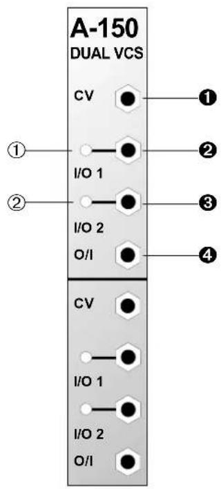
Indicators:
① LED: indicator for in / output ②
② LED: indicator for in / output ③
In / Outputs:
① CV : input for digital control voltage
② I/O 1 : in / output 1
③ I/O 2 : in / output 2
④ O/I : common out / input
3. Indicators
① LED ... ② LED
LEDs ① and ② serve as status indicators, to show which of the two in / outputs ② and ③ is at that moment connected to the common out / input ④.
4. In / Outputs
① CV
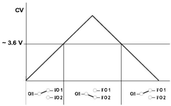
Socket ① is the input for the digital control voltage, whose level determines the switch state (see Fig. 1):
• CV low (< \~3.6 V): O/I ---- I/O 1
• CV high (> \~3.6 V): O/I ---- I/O 2
If a high frequency control voltage is used for switching, audio frequency modulation results (see Fig. 4 on page 5).
line
| Condition | CV | |---|---| | O/I | 0 | | I/O 1 | ~3.6 V | | I/O 2 | ~3.6 V | | O/I | 0 | | I/O 1 | ~3.6 V | | I/O 2 | ~3.6 V |Fig. 1: The A-150's switching behaviour
② I/O 1 • ③ I/O 2
These sockets are the in / outputs.
④ O/I
Socket ④ is the common out / input. Depending on the level of control voltage at input ① it's connected to socket ② or ③ (see Fig.1).
The switches are bi-directional: that is, two inputs can be connected to one output, and vice versa. The particular arrangement of inputs / outputs will always be clear from looking at what is patched to which socket.
Any signal from -8 V to +8 V can be controlled by the A-150. Voltages less than -8V or more than +8V will lead to malfunction of the module! It is possible to modify the module so that voltages in the range 0...+12V can be processed. You find a modification of the A-150 for signals in the range 0...+12V on our web site www.doepfer.com in the FAQ section (click to the FAQ button on the left side of the page).
Another solution for signals beyond -8V resp. +8V is to attenuate and/or to change the offset voltage of the signal. The A-129/3 attenuator/ offset generator can be used for both purposes.
From about March 2004 a new version of the A-150 is available. This allows the full A-100 voltage range -12V...+12V for the voltages at the O/I resp. I/O sockets. The new version can be identified at the pc board label "A-100 SYSTEM A-150 DUAL VC SWITCH VERSION 2" near the bus connector at the pc board edge.
5. User examples
Switching filter characteristics
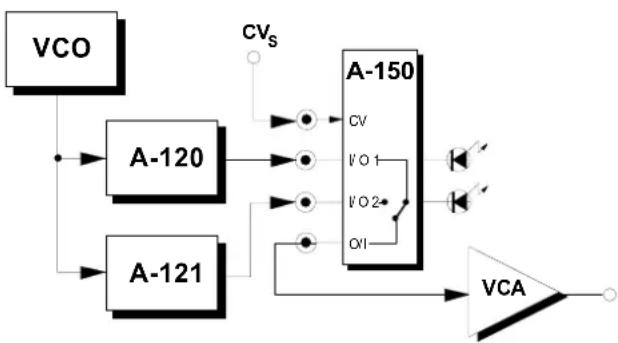
In the example in Fig. 2, with the help of an A-150, a signal can be switched between a 12dB and 24dB low pass filter.
The control voltage CV_s can for instance come from the CV output of a MIDI-CV interface (e.g. A-191), so that, for instance, a MIDI controller could be assigned to switch between filter types.
flowchart
graph TD
    VCO --> A120
    VCO --> A121
    A120 --> A150
    A121 --> A150
    A150 --> VCA
    A150 --> CVs
    A150 --> I/O1
    A150 --> I/O2
    A150 --> OI
Fig. 2: Switching between two filters with the A-150
Switching between modulation sources
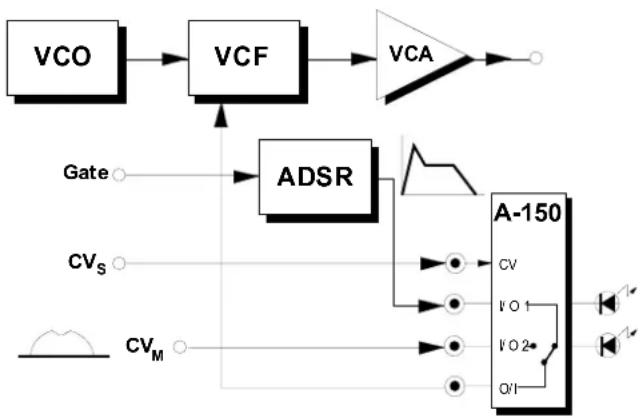
In the example in Fig. 3, the A-150 switches between two filter cut-off modulation sources. The control voltage CV_s (for instance from a MIDI controller) determines whether the ADSR (when CV_s = 0 V ) or the output from the mod wheel CV_M (when CV_s = +5 V ) controls the cut-off frequency of the filter.
flowchart
graph TD
    A["VCO"] --> B["VCF"]
    B --> C["VCA"]
    D["Gate"] --> E["ADSR"]
    F["CVs"] --> E
    G["CVM"] --> H["A-150"]
    H --> I["CV"]
    H --> J["VO 1"]
    H --> K["VO 2"]
    H --> L["Q/I"]
Fig. 3: Switching between modulation sources
Switching by audio-range signals
In Fig. 4, the A-150 is set up to switch the audio output of a VCO. The switching voltage is provided by the VCO's square wave output, with the result that at each half cycle, synchronised to the VCO frequency, the waveform changes to sawtooth. Try variations on this patch, with an independent VCO or LFO providing the switching voltage, different frequencies, etc..
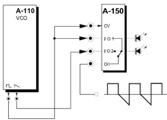
Fig. 4: Audio-range switching of an audio signal
A-150 Dual VCS
System A - 100
DOEPFER
Brand : Doepfer
Model : A-150
Category : Uncategorized