
SD-6276-SSVQ - Bouton poussoir électrique Seco-Larm - Free user manual and instructions
Find the device manual for free SD-6276-SSVQ Seco-Larm in PDF.


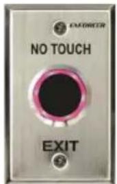
| Product Type | Outdoor Piezoelectric Request-to-Exit Pushbutton with Manual Override |
| Brand | Seco-Larm |
| Model | SD-6276-SSVQ (Single-Gang Plate with Manual Override) |
| Weight | 4 oz (113 g) |
| Operating Voltage | 12~24 VDC |
| Relay Rating | 5A @ 24VDC; two individually programmable outputs (NO/NC) |
| IP Rating | IP65 (weatherproof) |
| Operating Temperature | 32°F to 158°F (0°C to 70°C) |
| Plate Material | Stainless steel |
| LED Ring Colors | Standby: Red (default) or Green; Active: Green (default) or Red; configurable |
| Output Modes | Timed (1~30 seconds adjustable) or Toggle |
| Manual Override | Separate button for fail-safe operation; NO or NC wiring |
| Buzzer Output | On/Off via jumper JP3 |
| Mounting | Single-gang plate; screw mounting |
| Installation | Requires weatherproof backbox and sealing; follow local codes |
| Warranty | One year from date of sale against defects |
| Included Accessories | Mounting screws, manual override wires, manual |
| Maintenance | Clean with damp cloth; avoid harsh chemicals |
| Compliance | Must comply with national, state, and local building and egress codes |
| Safety Warning | Proper sealing required to prevent water ingress and electric shock; incorrect installation voids warranty |
Frequently Asked Questions - SD-6276-SSVQ Seco-Larm
User questions about SD-6276-SSVQ Seco-Larm
0 question about this device. Answer the ones you know or ask your own.
Ask a new question about this device
Download the instructions for your Bouton poussoir électrique in PDF format for free! Find your manual SD-6276-SSVQ - Seco-Larm and take your electronic device back in hand. On this page are published all the documents necessary for the use of your device. SD-6276-SSVQ by Seco-Larm.
USER MANUAL SD-6276-SSVQ Seco-Larm
Outdoor Piezoelectric
Request-to-Exit Pushbuttons
Manual
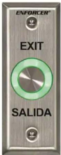
SD-6176-SSQ Slim|line plate "TOUCH/EXIT"
SD-6176-SS1Q Slimline plate "EXIT/SALIDA"
SD-6176-SSVQ Slimline plate, manual override
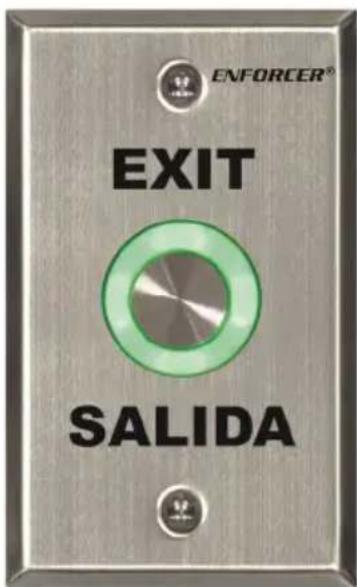
SD-6276-SSQ Single-Gang plate, "TOUCH/EXIT"
SD-6276-SS1Q | Single-Gang plate, "EXIT/SALIDA"
SD-6276-SSVQ Single-Gang plate, manual override
Features:
- Piezoelectric push buttons for indoor or outdoor use (IP65)
- LED ring around button changes from green to red or red to green when the button is pressed
-
Timed or toggle output
-
Includes separate manual override button in case power to piezoelectric push button fails
- Relay rated 5A@24VDC with two individually programmable outputs (NO/NC)
Introduction:
| Operating voltage 12~24VDC | ||
| Contact rating 2.5A@24 VAC/VDC | ||
| Ring LED | Standby | Red |
| Active | Green | |
| Output time 1~30s, Toggle | ||
| IP rating IP65 | ||
| Operating temperature 32°~158°F (0°~70°C) | ||
| Plate material Stainless steel | ||
| Weight | Single-Gang | 3.5-oz (99g) |
| Single-Gang w/ manual override | 4-oz (113g) | |
| Slimline | 2.6-oz | |
| Slimline w/ manual override | 3.1-oz | |
Parts List:
1x Piezoelectric push button 2x Wires for manual override
1x Manual 2x Mounting screws
Overview:

*SD-6176-SSVQ and SD-6276-SSVQ with Manual Override button shown, other models similar.
Installation:
- Prepare wiring to provide 12\~24 VDC power and connect devices to the relay outputs.
NOTE: The device includes one relay with two outputs. Outputs trigger simultaneously but can be configured independently. To set the output modes, see Relay Output Modes on page 3. - Remove the plastic cover from the rear of the switch and carefully pierce the rubber grommet.
- SD-6176-SSVQ and SD-6276-SSVQ: Wire the manual override button. See page 3.
- Wire the switch according to the diagram on the right.
- Connect (-) and (+) to a 12\~24 VDC power source.
- Connect other devices to Output 1 or 2.
- Replace the plastic switch cover and screw the plate onto the mounting surface
*SD-6176-SSVQ and SD-6276-SSVQ only.
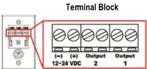
Wiring the Manual Override: SD-6176-SSVQ and SD-6276-SSVQ Only
Connect the manual override button with included wires
Wiring for N.O.:
Connect the two wires between the NO and COM terminals of the override button and the Output 1 or 2 terminals on the switch.

Wiring for N.C.:
Connect the two wires between the NC and COM terminals of the override button and the Output 1 or 2 terminals on the switch.
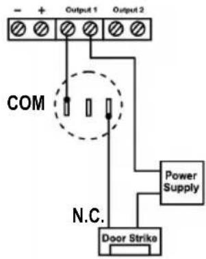
Notes:
- Remove the thin panel on the bottom of the plastic cover to allow wiring to pass through.
- There is only one relay, wiring the button to either output will allow the other output to trigger simultaneously.
- Do not connect the manual override button to more than one output.
- When wiring for either N.O. or N.C., be sure to also set the Relay Output Mode to N.O., as described below. If Relay Output Mode and override button wiring do not match, the product may not function as expected

Configuring the Pushbutton:
1. Buzzer Output
Default:ON

Use the buzzer output jumper JP3 to program the buzzer output. Placing the jumper on the left turns buzzer output ON. Placing the jumper on the right turns buzzer outputs OFF.
2. Relay Output Mode
Default: N.O

Outputs 1 and 2 can be set independently using jumpers JP1 and JP2. Note: Both outputs trigger simultaneously. Place the jumper on the right for N.O. operation and on the left for N.C. operation
3. LED Ring Colors
Default: OFF

ON: LED is green while in standby, and turns red when triggered. OFF: LED is red while in standby, and turns green when triggered.
4. Switch Output Type
Default: Timer
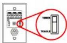
TIMER: When set to TIMER, pressing the switch will trigger the relay for the set time. Set the time using the trimpot as described above. TOGGLE: When set to TOGGLE, pressing the switch will cause the relay to trigger until the switch is pressed
5. Time Adjustment
Default: 1s

Output duration is adjustable 1\~30 seconds. (Must be set to 'Timer' in step 4) Gently rotate the trimpot using a Philips head screwdriver. Counterclockwise decreases the output time. Clockwise increases the output time.
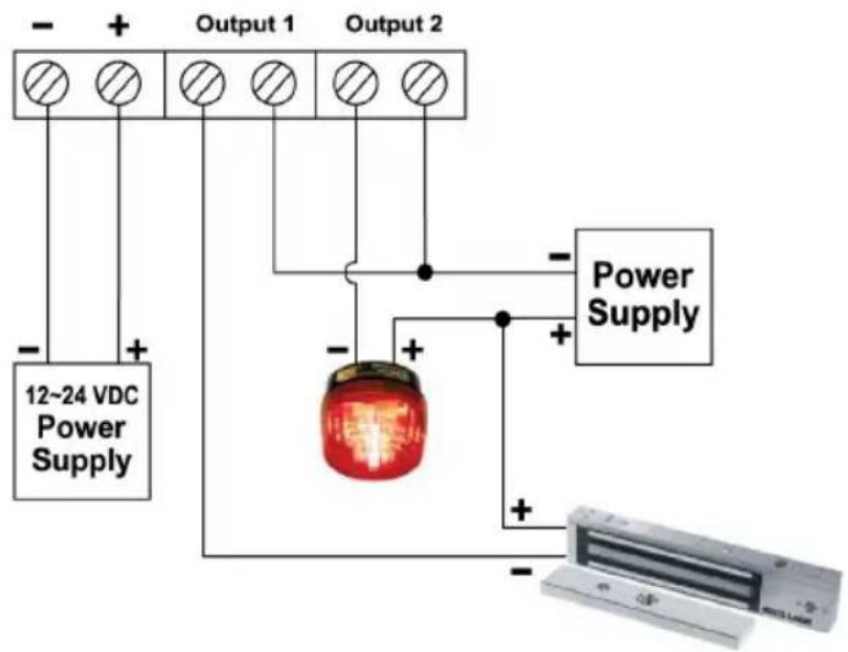
Sample Installation: Electromagnetic Lock (Fail-Safe) with Strobe Light
Also Available from SECO-LARM®:
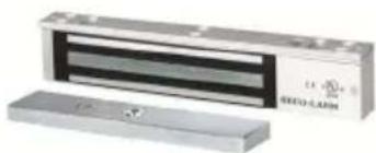
Electromagnetic
Locks
Request-to-Exit Plates
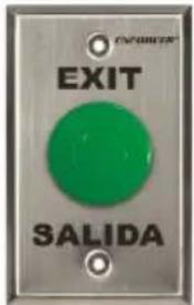
No-Touch
Request to Exit
IMPORTANT WARNING: For a weatherproof installation, ensure the unit is installed in a waterproof backbox, and that the faceplate and faceplate screws are properly sealed. Incorrect mounting may lead to exposure to rain or moisture in the enclosure which could cause a dangerous electric shock, damage the device and void the warranty. Users and installers of this product are responsible for ensuring this product is properly installed and sealed.
IMPORTANT: Users and installers of this product are responsible for ensuring that the installation and configuration of this product complies with all national, state, and local laws and codes related to locking and egress devices. SECO-LARM will not be held responsible for the use of this product in violation of any current laws or codes.
WARRANTY: This SECO-LARM product is warranted against defects in material and workmanship while used in normal service for one (1) year from the date of sale to the original customer. SECO-LARM's obligation is limited to the repair or replacement of any defective part if the unit is returned, transportation prepaid, to SECO-LARM. This Warranty is void if damage is caused by or attributed to acts of God, physical or electrical misuse or abuse, neglect, repair or alteration, improper or abnormal usage, or faulty installation, or if for any other reason SECO-LARM determines that such equipment is not operating properly as a result of causes other than defects in material and workmanship. The sole obligation of SECO-LARM and the purchaser's exclusive remedy, shall be limited to the replacement or repair only, at SECO-LARM's option. In no event shall SECO-LARM be liable for any special, collateral, incidental, or consequential personal or property damage of any kind to the purchaser or anyone else.
NOTICE: The SECO-LARM policy is one of continual development and improvement. For that reason, SECO-LARM reserves the right to change specifications without notice. SECO-LARM is also not responsible for misprints. All trademarks are the property of SECO-LARM U.S.A., Inc. or their respective owners. Copyright © 2019 SECO-LARM U.S.A., Inc. All rights reserved.
SECO-LARM® U.S.A., Inc.
16842 Millikan Avenue, Irvine, CA 92606 Website: www.seco-larm.com
Phone: (949) 261-2999 | (800) 662-0800 Email: sales@seco-larm.com

PIHWK1
Order Part# xxx-xxx%
MI_SD-6x76-SSxQ_190628.docx
4 SECO-LARM U.S.A., Inc.
- OUTDOOR PIEZOELECTRIC
- REQUEST-TO-EXIT PUSHBUTTONS
- MANUAL
- FEATURES
- PARTS LIST
- INSTALLATION
- WIRING THE MANUAL OVERRIDE: SD-6176-SSVQ AND SD-6276-SSVQ ONLY
- WIRING FOR N.O
- WIRING FOR N.C
- NOTES
- CONFIGURING THE PUSHBUTTON
- BUZZER OUTPUT
- RELAY OUTPUT MODE
- LED RING COLORS
- SWITCH OUTPUT TYPE
- TIME ADJUSTMENT
- ALSO AVAILABLE FROM SECO-LARM®
- SECO-LARM® U.S.A., INC
- 4 SECO-LARM U.S.A., INC
Brand : Seco-Larm
Model : SD-6276-SSVQ
Category : Bouton poussoir électrique