
AS9403 - Turntable MAGNAVOX - Free user manual and instructions
Find the device manual for free AS9403 MAGNAVOX in PDF.


| Product Type | Combination audio system with turntable, tuner, cassette deck, amplifier |
| Model Number | AS9403 (also AS9400) |
| Brand | Magnavox (Philips) |
| Turntable Speed | 33 and 45 RPM |
| Turntable Drive | Belt drive (implied by auto-return mechanism) |
| Turntable Operation | Manual start with lever; auto-return at end of record |
| Cartridge/Stylus | Replaceable stylus unit (see Figs. 7 and 8) |
| Speaker Impedance | Minimum 8 ohms |
| Speaker Configuration | Front (Normal) and Rear (Surround Sound) terminals |
| Power Supply | AC mains; voltage indicated on rear type plate |
| Power Consumption | Not specified |
| Remote Control | Infrared remote with batteries (2x1.5V R03/UM4/AAA) |
| Dimensions | Not specified; typical for component system approx. 430mm wide |
| Weight | Not specified |
| Inputs | PHONO IN, CD.TV IN, FM antenna (300 ohms), AM antenna, SW antenna (some versions) |
| Outputs | Speaker terminals (2 pairs), Headphones (8-1000 ohms), RC OUT for remote control of CD player |
| Cassette Deck | Two decks (Deck I record/play; Deck II play only); high speed dubbing |
| Tuner Bands | FM, AM, SW (shortwave not on all versions) |
| Preset Stations | 20 presets |
| Cleaning | Turntable: replace stylus; Cassette: heads clean every 15 hours with alcohol |
| Safety | Polarized plug; do not expose to moisture; follow grounding instructions for antenna |
| Warranty | One year carry-in labor and parts (US, Puerto Rico, Virgin Islands) |
Frequently Asked Questions - AS9403 MAGNAVOX
User questions about AS9403 MAGNAVOX
0 question about this device. Answer the ones you know or ask your own.
Ask a new question about this device
Download the instructions for your Turntable in PDF format for free! Find your manual AS9403 - MAGNAVOX and take your electronic device back in hand. On this page are published all the documents necessary for the use of your device. AS9403 by MAGNAVOX.
USER MANUAL AS9403 MAGNAVOX
MAGNAVOX

AS 9400 / AS 9403
Combination
WARNING
TO REDUCE THE RISK OF FIRE OR ELECTRIC SHOCK, DO NOT EXPOSE THIS APPLIANCE TO RAIN OR MOISTURE.
The Model and Serial Number of your unit will be found on the rear of the set. Please record the Model and Serial Number in the space provided below.
MODEL NUMBER: AS 9400 / AS 9403
SERIAL NUMBER:
This set complies with the FCC-Rules, Part 15.

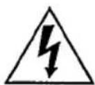
This symbol is intended to alert the user of the presence of uninsulated 'dangerous voltage' within the product's enclosure, that may be of sufficient magnitude to constitute a risk of electric shock to persons.

This symbol is intended to alert the user of the presence of important operating and maintenance (servicing) instructions in the literature accompanying the appliance.
SAFETY INSTRUCTIONS
Read before operating equipment
This product was designed and manufactured to meet strict quality and safety standards. There are, however, some installation and operation precautions which you should be particularly aware of
1 Read Instructions - All the safety and operating instructions should be read before the appliance is operated 2 Retain Instructions - The safety and operating instructions should be retained for future reference 12 Power-Cord Protection - Power supply cords should be routed so that they are not likely to be walked on or pinched by items placed upon or against them, paying particular attention to cords and plugs, convenience receptacles, and the point where they exit from the appliance
3 Heed Warnings - All warnings on the appliance and in the operating instructions should be adhered to 4 Follow Instructions - All operating and use 13 Cleaning - The appliance should be cleaned only as recommended by the manufacturer 14 Power Lines - An outdoor antenna should be located away from power lines
instructions should be followed 5 Water and Moisture - The appliance should not be used near water - for example, near a bathtub, washbowl, kitchen sink, laundry tub, in a wet basement or near a swimming pool, etc 6 Carts and Stands - The appliance should be used only with a cart or stand that is recommended by the manufacturer 15 Outdoor Antenna Grounding - If an outside antenna is connected to the receiver, be sure the antenna system is grounded so as to provide some protection against voltage surges and built up static charges Section 810 of the National Electric Code, ANSI/NFPA No 70-1984, provides information with respect to proper grounding of the mast and supporting structure, grounding of the lead-in
6A An appliance and cart combination should be moved with care Quick stops, excessive force, and uneven surfaces may cause the appliance and cart combination to overturn supporting structure, grounding of the lead-in wire to an antenna discharge unit, size of grounding connectors, location of antenna-discharge unit, connection to grounding electrodes, and requirements for the grounding electrode. See Fig A.
- Wall or Ceiling Mounting - The appliance should be mounted to a wall or ceiling only as recommended by the manufacturer
- Ventilation - The appliance should be situated so that its location or position does not interfere with its proper ventilation. For example, the appliance is not intended for a hard, safe run, or
should not be situated on a bed, sofa, rug, or similar surface that may block the ventilation openings; or, placed in a built-in installation, such as a bookcase or cabinet that may impede the flow of air through the ventilation openings 9 Heat - The appliance should be situated away from heat sources such as radiators, heat registers, steers, or other appliances including 18. Damage Requiring Service - The appliance should be serviced by qualified service personnel when: A The power-supply cord or the plug has been damaged, or B Objects have fallen, or liquid has spilled into the appliance, or
C The appliance has been exposed to rain, or D The appliance does not appear to operate normally or exhibits a marked change in performance, or E The appliance has been dropped, or the enclosure damaged
- Grounding or Polarization - The precautions that should be taken so that the grounding or polarization means of an appliance is not defeated 19 Servicing - The user should not attempt to service the appliance beyond that described in the operating instructions All other servicing should be referred to qualified service personnel
EXAMPLE OF ANTENNA GROUNDING ACCORDING TO THE NATIONAL ELECTRIC CODE INSTRUCTIONS CONTAINED IN ARTICLE 810 - 'RADIO AND TELEVISION EQUIPMENT'

Use No 10 AWG (5.3 mm²) copper. No 8 AWG (8.4 mm²) aluminum. No 17 AWG (1.0 mm²) copper-clad steel or bronze wire, or larger, ground wire Mount the antenna discharge unit as close as possible to where the lead-in wire enters the house
⑥ Secure the antenna lead-in and ground wires to the house with stand-off insulators spaced from 4-6 feet (1 22-1 83 m) apart ⑦ Use jumper wire not smaller than No 6 AWG (13.3 mm²) copper, or the equivalent, when a separate antenna-grounding electrode is used. See NEC Section 810-21 (J)
NOTE TO THE CATV SYSTEM INSTALLER:
This reminder is provided to call the CATV system installer's attention to Article 820-22 of the NEC that provides guidelines for proper grounding and, in particular, specifies that the cable ground shall be connected to the grounding system of the building, as close to the point of cable entry as practical.
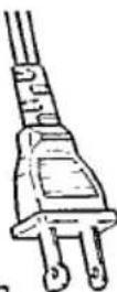
AC POLARIZED PLUG
Operating Instructions
INSTALLATION
- Unpack all parts and remove protective material.
- Fully tighten both record player transit screws ⚠ (Fig. 3). Screw in clockwise direction (record player not on all versions).
- Insert the batteries of the remote control unit, as indicated in the battery compartment. (Fig.10)
- Do not cover any vents and make sure that there is sufficient ventilation room around the unit.
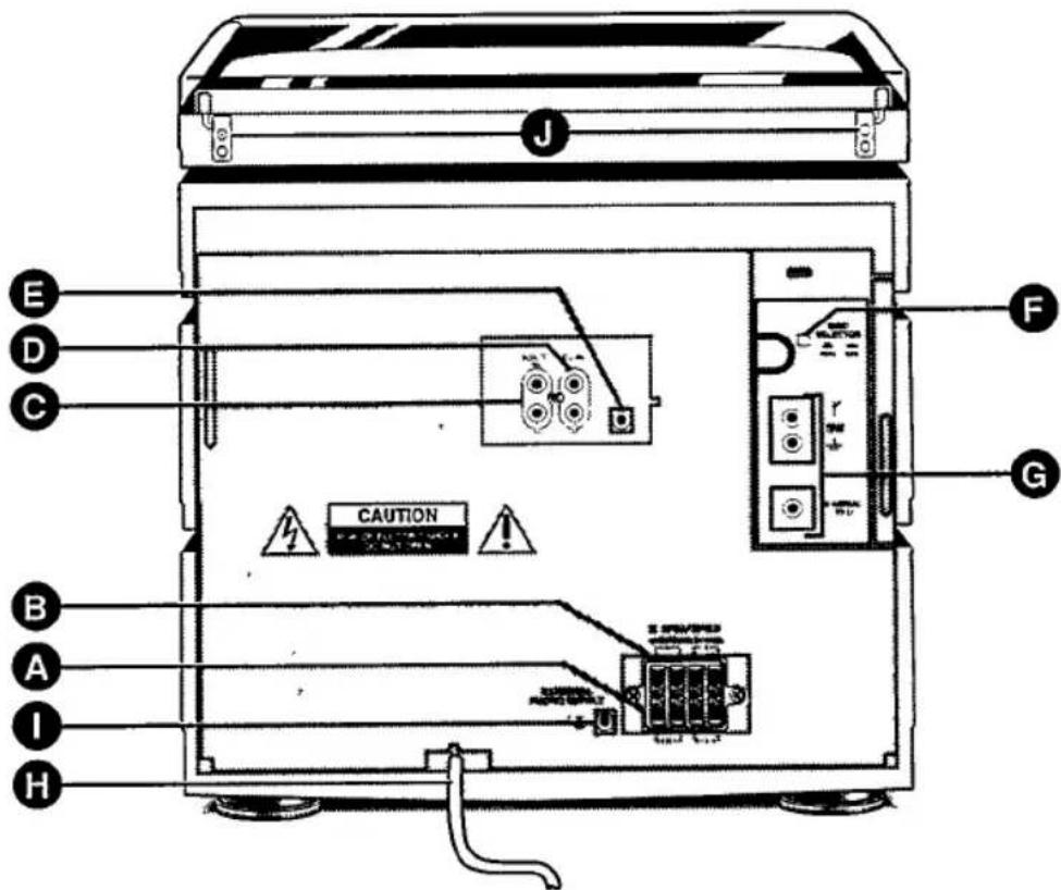
CONNECTIONS, Fig. 2
Ⓐ (NORMAL) Speaker terminals for two front speakers, minimum impedance 8 ohms.
⑧ (SURROUND SOUND) Speaker terminals for two rear speakers, minimum impedance 8 ohms. For details, see Fig. 6 and GENERAL INFORMATION.
© CD.TV IN, for connection a compact disc player, or for the sound channel of a TV set, etc.
⑥ PHONO IN terminals, for connection record player (not on all versions).
€ RC OUT, can be connected (with an optional cord) to the REMOTE IN of your CD player, if it has a corresponding jack for remote control.
⑤ GRID SELECTOR (not on all versions), see TUNER.
⑥ terminal for FM antenna, 2× screw, 300 ohms. The auxiliary antenna supplied can be connected to this terminal. Aim for optimum reception. For good stereo reception use of an FM outdoor antenna is recommended. Some versions also have two screws for SW antenna and ground connection.
power cord. Do not connect the unit to the power without having checked whether the voltage on the type plate corresponds with the local power voltage. If it does not, consult your dealer. The type plate is on the rear of the unit.
① PHONO SUPPLY jack (not on all versions), for connection a record player without its own power supply section.
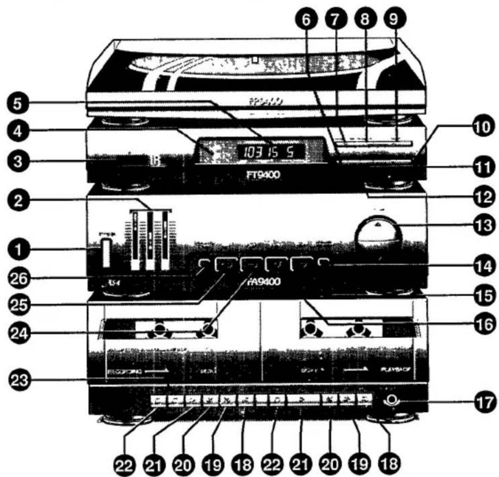
CONTROLS, Fig. 1
① POWER on/off switch.
To disconnect the set from the power completely, withdraw the power plug from the wall outlet.
② Tone controls
③ IR INFRA RED remote sensor, receives the infra red signals from the remote control unit.
④ STAND BY indicator, flashes when using a remote control.
⑤ Display, shows:
● The sound sources: CASS, Add or Cd.
- in TUNER mode:
- a frequency in kHz or MHz and the selected wavebands FM, AM and SW (short wave not available in all versions),
- STEREO, to indicate when an FM stereo station has been received,
- The preset station number,
- PROGR to indicate that the frequency can be programmed.
⑥ BAND selector button.
⑦ PRESET DOWN, for tuning to preset stations.
⑧ PRESET UP, for tuning to preset stations.
⑨ TUNING UP, for tuning to higher frequencies.
⑩ TUNING DOWN, for tuning to lower frequencies.
⑪ MONO button: to reduce interference caused by weak stereo reception.
⑫ PROGR button, to program preset stations.
⑬ VOLUME control.
⑭ DYNAMIC BASS BOOST button with indicator, for extra bass tones.
⑮ CD.TV button, for a compact disc player, or a TV connected to the CD.TV IN terminals ©.
⑯ PHONO button, for the record player.
⑰ PHONES, for connection stereo headphones (impedance 8-1000 ohms). The speakers are switched off when using headphones.
⑱ PAUSE button.
⑲ WIND button.
⑳ REW button.
②1 PLAY button.
② STOP/EJECT.
②3 RECORD button (deck I).
⑳ TUNER button.
25 TAPE button.
26 HIGH SPEED DUBBING selector with indicator.
Record player, Fig. 3
△ Adaptor disc for 45 rpm records.
Transit protection screws.
⚠ Lever to raise or lower the tone arm.
33-45 selector for selecting the appropriate rpm.
△ Fixing clamp for the tone arm
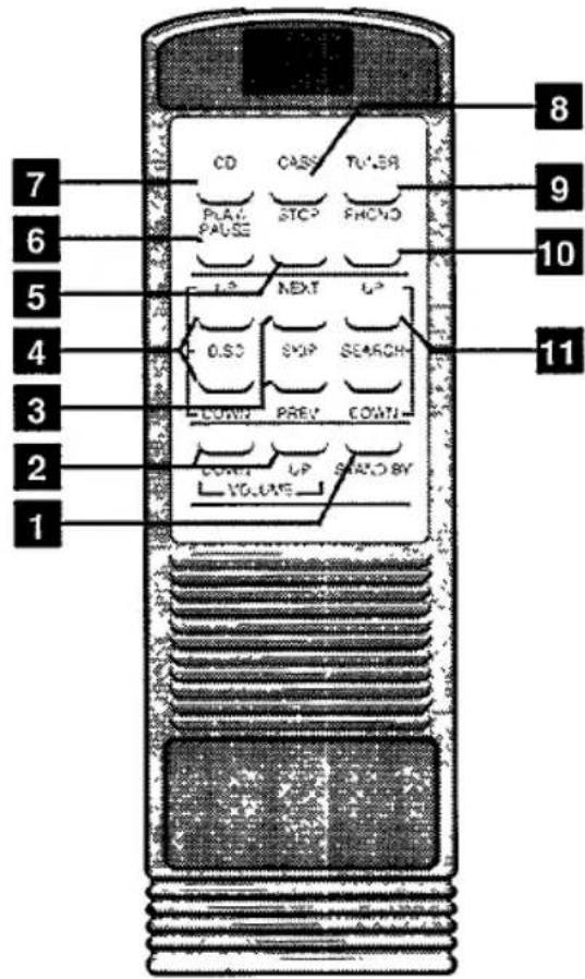
Remote control unit, Fig. 10
1 STAND BY button.
2 VOLUME UP/DOWN buttons.
3 SKIP NEXT/PREV, for selecting preset stations and operating a CD player.
4 DISC UP/DOWN buttons, for selecting the discs in a CD autochanger.
5 STOP button, for a CD player.
6 PLAY/PAUSE button, for a CD player.
7 CD button, for selecting a compact disc player.
8 CASS button, for selecting the cassette decks.
9 TUNER button, for selecting the tuner.
10 PHONO button, for selecting the record player.
11 SEARCH UP/DOWN tuning buttons.
USING THE REMOTE CONTROL UNIT
- Connect the jack RC OUT (Fig. 2) to the REMOTE IN or RC5 IN jack of your Compact Disc player. An optionally available cord can be used for this purpose.
● Before pressing any other remote control button, first press: - CD.TV [7], if you wish to operate your CD player.
- CASS [8], if you wish to operate the cassette decks (volume and standby only).
- TUNER [9], if you wish to operate your tuner.
- PHONO 10, if you wish to operate the record player (volume and standby only).
AMPLIFIER
- Switch on with POWER ①. The unit selects TUNER mode.
- To select another sound source, press the relevant function button, e.g. TAPE ⑲, PHONO ⑯ or CD.TV ⑮.
- Press VOLUME ⑬ to the desired sound level, or use the remote control unit.
- Adjust the tone using the controls ② and/or DYNAMIC BASS BOOST button ⑭.
TUNER
Note: Some versions of this unit are fitted with a grid selector (⑤) at the rear, which selects (with the POWER switched off) the size of the frequency step between adjacent channels in the AM band. In North and South America it should be set to 10 kHz.
In all other parts of the world to 9 kHz. If your unit has no such a selector, then it has been preset in the factory for correct operation in your area.
Tuning
- Press TUNER button 24.
- Select the tuning range with button ⑥.
- Tune to the desired station:
- Press button ⑨ UP or ⑩ DOWN for more than 0.5 seconds. Then release this button. The frequency on the display now changes continuously until a station of sufficient strength has been found. Repeat this procedure, if it is not the station of your choice.
● To tune to weak stations briefly press UP or DOWN as often as is necessary for optimum reception, or until you read the correct frequency. - If there is interference noise during FM stereo reception, set button ⑪ to the MONO position.
PRESET TRANSMITTERS
Twenty preset stations can be programmed. When tuning to a programmed station, the memory location (0 to 19) is indicated in the display.
Programming
- Press PROGR ⑫. Display ⑤ indicates PROGR.
● Tune to the frequency of the station to be programmed as described before under TUNING. - Select a memory location number (0 up to 19) with the buttons PRESET DOWN ⑦ or PRESET UP ⑧.
- Press button PROGR ⑫. The frequency is now entered in the memory and the indication PROGR disappears from display ⑤.
Tuning to preset stations
- Press TUNER button 24.
- Select the memory location number (0 up to 19) of the desired station with the buttons PRESET DOWN ⑦, PRESET UP ⑧, or the SKIP NEXT/PREV buttons ③ of the remote control unit.
RECORD PLAYER (not on all versions)
- Press PHONO button ⑯.
- Place a record on the turntable. For records with a large center hole, use the adapter ⚠.
- Remove the stylus protector by pulling it forwards.
- Use selector △ to select the appropriate speed.
● Make sure that the arm is not fixed with clip ⚠. - Move lever ⚠ to the ▼ position.
- Move the tone arm inwards. This starts the record player. Position the arm above the desired track.
- Move the lever ⚠ carefully to the ▼ position. The record starts to play.
● The record can be interrupted by moving lever ⚠ to the ▼ position. To continue, move lever ⚠ to the ▼ position.
● The record player stops automatically at the end of the record and the arm returns to its support. - Stopping can be done at any given moment. Set lever ⚠ to the ▼ position and then move the player arm outwards. When you reach the support, the turntable will stop.
- Set lever ⚠ to the ▼ position, secure the arm and replace the stylus protection cover.
Note: If the auto-return mechanism of the record player fails to work the first time after transit, move the tone arm towards the center by hand. The mechanism will activate, and the tone arm will return. Do not use force; be positive, but gentle. Once the auto-return mechanism has been reset in this manner, it will function automatically thereafter.
CASSETTE DECKS
Recording (deck I only)
- For recording, always use NORMAL or FERRO cassettes (IEC type I).
- For playback, any cassette type can be inserted.
Copyright: Recording is permissible insofar as copyright or other rights of third parties are not infringed.
Prepare the set for recording as follows:
- Select the sound source with one of the buttons TUNER ⑳, PHONO ⑯ or CD.TV ⑰.
- Open the cassette compartment of deck I with the STOP/EJECT button ② and place the cassette in the compartment, with the open side downwards and the full spool on the left (see Fig. 4).
-
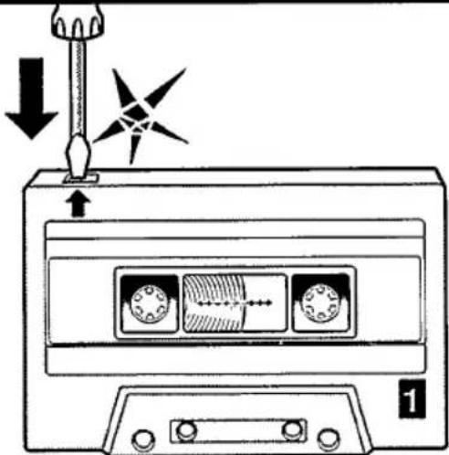
Do not use cassettes with tabs removed (Fig. 5) for making a recording. They prevent the RECORD button ②3 from functioning properly.
-
Press the PAUSE button ⑱ of deck I.
- Press the RECORD button ②3.
- Release PAUSE button ⑱ to start recording.
- For short pauses press PAUSE 18 of deck I. Press PAUSE again to resume recording.
- Press STOP/EJECT of deck I to stop recording.
Playback
- Press the TAPE button 25.
- Playback is possible with both decks I or II. If both PLAY buttons are pressed simultaneously, deck II has priority.
- Press STOP/EJECT button 22 to open the cassette compartment. Place a recorded cassette in the compartment, open side downwards and full spool on the left (see Fig. 4).
- Press the PLAY button ②1.
- For short pauses press the PAUSE button ⑱. To resume playback, press the PAUSE button again.
- Press STOP/EJECT ② to stop playback.
Continuous playback
- Press the TAPE button 25.
- Open both cassette compartments with the STOP/EJECT buttons ② and place a recorded cassette in each compartment (Fig. 4).
- Press PLAY button ② of deck II.
- Press PAUSE button ⑱ of deck I.
- Press PLAY button ② of deck I.
- At the end of the cassette in deck II (or when STOP/EJECT of deck II is pressed), deck I will start playing back.
Dubbing - Copying from deck II to deck I
- Press the TAPE button ⑲.
- Select the dubbing speed using the HIGH SPEED DUBBING button 😊. Do not press this button during dubbing.
- Press both STOP/EJECT buttons and insert a recorded cassette into deck II and a cassette which is suited for recording into deck I (fig. 4).
- Press PAUSE button ⑱ of deck I.
- Press the RECORD button ②3.
- Press PLAY (2) of deck II to start dubbing.
- To omit undesired passages, press PAUSE (18) of deck I; deck II will continue to play. To restart copying, press PAUSE of deck I once more.
Using the PAUSE button of deck II, deck I will record a blank part. - Press both STOP/EJECT buttons to stop dubbing. Important: During dubbing the buttons TUNER ⑳, PHONO ⑯ or CD.TV ⑮ should not be pressed.
Fast winding
- Press the WIND button ⑲ or the REW button ⑳ for fast winding in both directions.
● To stop fast winding, press STOP/EJECT button ②.
End of the cassette
When the end of the tape is reached during recording, playback and fast forwarding or rewinding, the pressed recorder buttons will automatically be released.
GENERAL INFORMATION
Tape recording
● The tape in the cassette is secured at both ends with leader tape. At the beginning of the cassette nothing will be recorded for 6 to 7 seconds!
- Accidental erasure can be prevented by breaking the small tab in the top left-hand corner on the back of the cassette (see Fig. 5). This protection can be reversed with a small piece of adhesive tape.
- Store the cassettes at room temperature and do not put them too close to magnets and transformers of e.g. TVs and speaker boxes.
Connection of speakers
- Speakers with a minimum of 8 ohms can be connected to the terminals Ⓐ and Ⓑ (see Fig. 2 and 6).
- When using two speakers, use the NORMAL terminals Ⓐ.
- When using four speakers, use terminals Ⓐ for the front speakers and the SURROUND SOUND terminals Ⓤ for the rear speakers.
- One of the two wires of a speaker cord is marked, e.g. with a color or rib. Connect the marked wire to the red terminal, the non-marked wire to the black terminal. Make sure that the color combination of wire and terminal is exactly the same for each speaker.
'Surround sound'
Connect the second pair of speakers to obtain a surround sound effect: two 'A' speakers in front of the listener and the two rear speakers 'B' for the 'surround sound' effects. The function of the surround sound speakers is to support the front sound information.
Positioning the speakers
The best position can be found by experimenting. Bass reproduction is amplified by placing the speakers on the floor. Placing speakers behind curtains, etc. has an unfavourable effect on treble reproduction. Try to keep the arrangement as symmetrical as possible.
Record player maintenance
Because self-lubricating bearings are used, the record player requires no maintenance.
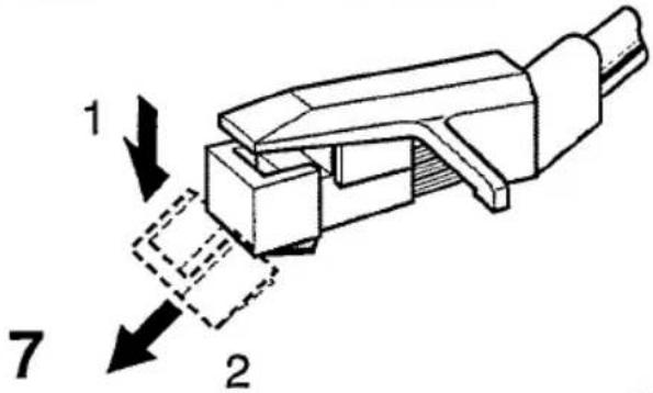
- The stylus unit can be removed in one piece and replaced (see Figs. 7 and 8). Carefully press the front edge of the stylus unit downwards until it comes loose. Mount a new stylus unit by first sliding the rear
part of the stylus unit into place. Then push the foremost part upward until you can feel and hear the stylus click into place.
● The dust cover is fitted with frictional hinges. It can be set to almost any position. If this is not the case, carefully tighten the screws ⭕, Fig. 2. The hinges must not be lubricated!
Recorder maintenance
To ensure a good recording and playback quality, clean the heads Ⓐ and Ⓑ, capstan Ⓓ and pressure roller Ⓞ after approx every 15 hours of operation (see Fig. 9). You can use a cleaning cassette, or a piece of cotton wool dipped in alcohol. Make sure that the unit is not connected to the power. The mechanism must not be lubricated!
1
2

 |  | |
| 4 | 5 | |
 |  |  |
 |  | |
| 6 | 8 | |
 | ||
| 9 | ||


2 x 1.5 V R03 / UM4 / AAA
LIMITED WARRANTY
AUDIO PRODUCTS
● One (1) Year Carry-In Labor Warranty
● One (1) Year Carry-In Service Parts Warranty
* For purchases outside the U.S., see applicable warranty from country of purchase.
This warranty gives you specific legal rights, and you may also have other rights which vary from state to state.
Replacement Parts and Service Labor
For one (1) year from the date of purchase, an Authorized Service Center will replace any part found defective and will repair any product defect without charge to you for parts or labor.
Replacement parts installed during the warranty period are warranted only for the balance of the original warranty period.
Who is Protected? ... Where?
This warranty is extended to the original retail purchaser for products purchased and used in the U.S.A., Puerto Rico and the Virgin Islands. If you move within these areas, an Authorized Service Center in your area will honor this warranty for the remainder of the original warranty period.
What the Purchaser Must Do
Before you call for service, check your operating instruction booklet. A slight adjustment of the customer controls discussed in your instruction booklet may save you a service call.
How to Get Warranty Service
To obtain Warranty Service you must deliver your Audio Unit, with evidence of the purchase date, to an Authorized Service Center for repair if service is required during the warranty period. When repair is completed, you must pick up the unit at the Service Center
Warranty Exclusions
Your Warranty Does Not Cover:
- Labor charges for installation or set-up, adjustment of customer or preference controls, and installation or repair of audio antenna systems outside the unit.
- Product repair and/or part replacement because of misuse, accident, unauthorized repair or other cause not within the control of Philips Consumer Electronics Company.
- Reception problems caused by signal conditions or antenna systems outside the unit.
— An Audio Unit purchased, used or serviced outside the U.S.A., Puerto Rico and the Virgin Islands, or used for commercial or institutional purposes (included but not limited to products used for rental purposes)
- Incidental or consequential damages resulting from the product or use of the product. Some states do not allow the exclusion of incidental or consequential damages, so the above exclusion may not apply to you.
ALL IMPLIED WARRANTIES INCLUDING IMPLIED WARRANTIES OF MERCHANTABILITY AND FITNESS FOR A PARTICULAR PURPOSE, ARE LIMITED IN DURATION TO THE DURATION OF THIS EXPRESS WARRANTY. Some states do not allow limitations on how long an implied warranty lasts, so the above limitation may not apply to you
Important Reminder
Please fill out and mail your Warranty Registration Card promptly. It will be easier for us to notify you if it should ever be required. The return of the Warranty Registration Card is not a condition to Warranty Coverage
Philips Service Company
P.O. Box 55 - Jefferson City - Tennessee TN 37760
(615) 475-0317
How To Get Service On Your Audio Unit Through Philips Factory Service
To obtain expedient IN or OUT-of-warranty repair:
- Contact the nearest Philips Factory Service Center, listed to the right, to obtain the cost of out-of-warranty repair for your model product. *
- Pack your Audio Unit in a suitable carton for safe shipment.
- Ship the product to the nearest Factory Service Center along with a letter inside the carton describing the problem. Be sure that the letter includes your name, address and telephone number. Enclose your check or money order in the amount quoted you by the Factory Service Center.
- When your product is received, it will be repaired in a manner that meets Philips' high quality standards and returned to you by prepaid transportation.
• IN or OUT-of-warranty service can also be obtained by delivering the Audio Unit to a Service Center in your area.
Philips Factory Service Centers
Atlanta - 1898 Leland Drive,
Manetta, GA 30067 ..... (404) 952-3279
Boston - 41 Second Avenue,
Burlington, MA 01803 ..... (617) 272-4825
Chicago - 500 East Touhy Avenue,
Des Plaines, IL 60018 ..... (708) 827-9405
Cleveland - 24090 Detroit Avenue - Rear,
Westlake, OH 44145 ..... (216) 899-2040
Connecticut - 77 Grassmere Avenue,
West Hartford, CT 06110 ..... (203) 233-5151
Dallas - 1413 Bradley Lane,
Carrollton, TX 75007 (214) 323-8335
Los Angeles - 12889 Moore Street,
Cerntos, CA 90701 (213) 637-7293
Miami - 2099 West Atlantic Boulevard, Pompano Beach, FL 33069 .... (305) 978-0467
New Jersey - 178 Manor Road,
East Rutherford, NJ 07073 ..... (201) 935-0600
New York - 116 Charlotte Avenue.
Hicksville, NY 11801 ..... (516) 933-1780
Philadelphia - 3599 Meadow Lane,
Cornwell Heights, PA 19020 ..... (215) 638-7500
Tennessee - 112 Polk Street,
Greeneville, TN 37743 .... (615) 636-5902
EL 3709-6
89/10
Philips Consumer Electronics Company
A Division of North American Philips Corporation
- WARNING
- SAFETY INSTRUCTIONS
- READ BEFORE OPERATING EQUIPMENT
- NOTE TO THE CATV SYSTEM INSTALLER
- OPERATING INSTRUCTIONS
- INSTALLATION
- CONNECTIONS, FIG. 2
- CONTROLS, FIG. 1
- RECORD PLAYER, FIG. 3
- REMOTE CONTROL UNIT, FIG. 10
- USING THE REMOTE CONTROL UNIT
- AMPLIFIER
- TUNER
- TUNING
- PRESET TRANSMITTERS
- PROGRAMMING
- TUNING TO PRESET STATIONS
- RECORD PLAYER (NOT ON ALL VERSIONS)
- CASSETTE DECKS
- RECORDING (DECK I ONLY)
- PREPARE THE SET FOR RECORDING AS FOLLOWS
- PLAYBACK
- CONTINUOUS PLAYBACK
- DUBBING - COPYING FROM DECK II TO DECK I
- FAST WINDING
- END OF THE CASSETTE
- GENERAL INFORMATION
- TAPE RECORDING
- CONNECTION OF SPEAKERS
- SURROUND SOUND
- POSITIONING THE SPEAKERS
- RECORD PLAYER MAINTENANCE
- RECORDER MAINTENANCE
- LIMITED WARRANTY
- AUDIO PRODUCTS
- REPLACEMENT PARTS AND SERVICE LABOR
- WHO IS PROTECTED? ... WHERE
- WHAT THE PURCHASER MUST DO
- HOW TO GET WARRANTY SERVICE
- WARRANTY EXCLUSIONS
- YOUR WARRANTY DOES NOT COVER
- IMPORTANT REMINDER
- HOW TO GET SERVICE ON YOUR AUDIO UNIT THROUGH PHILIPS FACTORY SERVICE
- TO OBTAIN EXPEDIENT IN OR OUT-OF-WARRANTY REPAIR
- PHILIPS FACTORY SERVICE CENTERS
- PHILIPS CONSUMER ELECTRONICS COMPANY
Brand : MAGNAVOX
Model : AS9403
Category : Turntable