
Retractor SM Network - Network accessory Extron - Free user manual and instructions
Find the device manual for free Retractor SM Network Extron in PDF.


| Product Type | Cable Retraction Module for TeamWork Collaboration Systems |
| Brand | Extron |
| Model | Retractor SM Network |
| Compatible Cable Interfaces | HDMI, DisplayPort to HDMI, Mini DisplayPort to HDMI, VGA |
| Cable Extension Length | Up to 3 ft (90 cm) |
| Pigtail Length | 6 ft (1.8 m) for under-table connection |
| Supported Video Resolutions | Up to 1920x1200, including 1080p/60 Deep Color and 2K |
| Share Button Functionality | Lights up when source is switched to main display |
| Retraction Method | Push-button release; cable is held at user-defined length |
| Mounting Orientations | Horizontal, vertical, angular |
| Compatible Enclosures | Cable Cubby Series/2, TMK 120 R Under Table Mount Kit |
| Required Mounting Kits | Retractor SM Cable Cubby Mount (Triple or Quad) or Horizontal Bracket Kit |
| Filler Module | Required for unused slots; includes blank and pass-through plates |
| Power Source | None; mechanical retraction, no external power needed |
| Safety Precautions | Controlled retraction to prevent injury; keep hands clear |
| Adjustability | Pulley tension and retraction speed (coarse and fine adjustment) |
| Warranty Period | 3 years from date of purchase |
| Color | Black |
Frequently Asked Questions - Retractor SM Network Extron
User questions about Retractor SM Network Extron
0 question about this device. Answer the ones you know or ask your own.
Ask a new question about this device
Download the instructions for your Network accessory in PDF format for free! Find your manual Retractor SM Network - Extron and take your electronic device back in hand. On this page are published all the documents necessary for the use of your device. Retractor SM Network by Extron.
USER MANUAL Retractor SM Network Extron
TeamWork "Show Me" Cable Retraction Modules
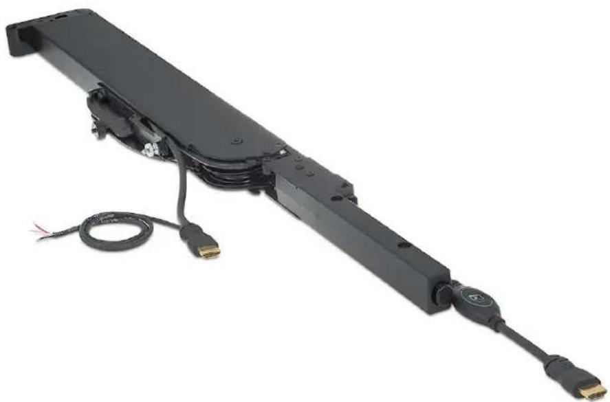
natural_image
Black electronic device with attached cable and connector, no visible text or symbolsSafety Instructions
Safety Instructions • English
WARNING: This symbol, , when used on the product, is intended to alert the user of the presence of uninsulated dangerous voltage within the product's enclosure that may present a risk of electric shock.
ATTENTION: This symbol, △when used on the product, is intended to alert the user of important operating and maintenance (servicing) instructions in the literature provided with the equipment.
For information on safety guidelines, regulatory compliances, EMI/EMF compatibility, accessibility, and related topics, see the Extron Safety and Regulatory Compliance Guide, part number 68-290-01, on the Extron website, www.extron.com.
Conventions Used in this Guide
Notifications
The following notifications are used in this guide:
DANGER:
CAUTION: Risk of minor personal injury.
NOTE: A note draws attention to important information.
Specifications Availability
Product specifications are available on the Extron website, www.extron.com.
Extron Glossary of Terms
A glossary of terms is available at http://www.extron.com/technology/glossary.aspx.
NOTE: For information on safety guidelines, regulatory compliances, EMI/EMF compatibility, accessibility, and related topics, see the “Extron Safety and Regulatory Compliance Guide” on the Extron website.
Copyright
© 2015 Extron Electronics. All rights reserved.
Trademarks
All trademarks mentioned in this guide are the properties of their respective owners.
The following registered trademarks®, registered service marks ^(SM) , and trademarks ^(TM) are the property of RGB Systems, Inc. or Extron Electronics:
| Registered Trademarks ^(8) |
| AVTrac, Cable Cubby, CrossPoint, eBUS, EDID Manager, EDID Minder, Extron, Flat Field, Global Configurator, GlobalViewer, Hideaway, Inline, IP Intercom, IP Link, Key Minder, LockIt, MediaLink, PlenumVault, PoleVault, PowerCage, Pure3, Quantum, SoundField, SpeedMount, SpeedSwitch, System INTEGRATOR, TeamWork, TouchLink, V-Lock, VersaTools, VN-Matrix, VoiceLift, WallVault, WindoWall, XTP, and XTP Systems |
| Registered Service Mark ^(SM) : S3 Service Support Solutions |
| Trademarks ^(TM) |
| AAP, AFL (Accu-Rate Frame Lock), ADSP (Advanced Digital Sync Processing), Auto-Image, CableCover, CDRS (Class D Ripple Suppression), DDSP (Digital Display Sync Processing), DMI (Dynamic Motion Interpolation), Driver Configurator, DSP Configurator, DSVP (Digital Sync Validation Processing), DTP, eLink, EQIP, FastBite, FlexOS, FOX, FOXBOX, IP Intercom HelpDesk, LinkLicense, MAAP, MicroDigital, NetPA, ProDSP, QS-FPC (QuickSwitch Front Panel Controller), Room Agent, Scope-Trigger, ShareLink, SIS, Simple Instruction Set, Skew-Free, SpeedNav, Triple-Action Switching, WebShare, XTRA, ZipCaddy, ZipClip |
Contents
Introduction ...... 1
About this User Guide .... 1
About the Retractor SM Module .... 1
Features....1
Getting Started .... 3
Planning 3
Determine Under-table Clearances .... 4
Retractor SM Cable Cubby 1200/1400
Mounting 5
Retractor SM Cable Cubby 500/700
Mounting 6
Pigtails....6
Prepare the Retractors 7
Installation 8
Retractor SM installation Overview ....8
Cable Cubby 1200 and Cable Cubby 1400
Enclosures....9
Retractor SM Cable Cubby Mount – Quad ..... 9
Retractor SM Cable Cubby Mount – Triple....10
Cable Cubby 1400 11
Cable Cubby 500 and Cable Cubby 700
Enclosures....12
Retractor SM Filler Module 13
Horizontal Mounting Bracket 14
Locking Screw....15
Connect the Cables....15
Initial Adjustments....16
Operation 17
Extend a Cable 17
Retract a Cable 17
Maintenance and Adjustments....18
Pulley System Adjustment 18
Speed Control 20
Speed Control Coarse Adjustment.... 20
Speed Control Fine Adjustment 20
Reference Information ......21
Retractor SM Part Numbers 21
Optional Accessories....21
Introduction
• About this User Guide
• About the Retractor SM Module
- Features
About this User Guide
This guide provides instructions and information for an experienced technician to install, adjust, and operate the Extron Retractor SM "Show Me" Cable Retraction Modules for HDMI, DisplayPort, and VGA in an Extron TeamWork Collaboration System and in compatible Cable Cubby Series/2 enclosures.
In this guide, the terms "system", and "retraction system" are used to refer to the TeamWork "Show Me" Cable Retraction Modules for HDMI, DisplayPort, and VGA in a TeamWork enclosure. The term "retractor", "retractor module", and "module" refer to an individual retractor in the system. Where differences in preparation, installation, operation, or maintenance occur, they are called out.
About the Retractor SM Module
The TeamWork "Show Me" Cable Retraction Module is a cable retracting device installed into, but not limited to, Extron Electronics TeamWork "Show Me" systems. The cable retraction system can be mounted into all current TeamWork enclosures.
The module allows extended cables to be retracted back into the enclosure for storage without force or gravity. It also prevents cables from tangling underneath the table as commonly seen with traditional gravity-fed systems. The retractor is a compact multi-pulley assembly that provides a smooth consistent return motion with the push of a button.
Each retractor comes pre-loaded with Extron tested and approved cable, optimized for the specific cable diameter and flexibility. The Retractor SM allows up to three feet of cable to be extended from the top of the enclosure and provides up to six feet of pigtail for connection of devices under the table.
Features
- Provides the user interface for digital or analog signals in a TeamWork collaboration system
- Convenient, easy to install cable retraction system designed for use with most Cable Cubby Series/2 cable access enclosures
• Also works with TMK 120 R Under Table Mount Kit - Simple. intuitive operation: Extend – Connect – Share
- "Share" button lights as it switches the connected source to the main presentation display
- Cables extend up to three feet (90 cm) — Also provides 6 feet (1.8 m) of pigtail for connecting to other AV products located beneath the mounting surface.
- Holds cable securely in place at a user-defined length
- Simple push-button release retracts cable into Cable Cubby enclosure after use.
- Adjustable cable retraction speed for smooth operation in horizontal or vertical mounting orientations — Cable extension and retraction mechanisms operate independently for greater reliability and longer cable life.
- Engineered for long life and reliability in high-utilization environments.
- Retractor SM HDMI —
• Male to male HDMI cable with 3-conductor pigtail for contact closure and tally
• Supports computer and video signals up to 1920x1200, including 1080p/60 Deep Color and 2K
- Ultra-flexible cable conforms to HDMI High Speed cable specifications
- Retractor SM DP-HDMI and Retractor SM MDP-HDMI —
- DisplayPort or Mini DisplayPort male to HDMI male cables with 3-conductor pigtail for contact closure and tally
- Provides connectivity between a dual-mode DisplayPort enabled source and an HDMI switcher
• Supports computer and video signals up to 1920x1200, including 1080p/60 Deep Color and 2K
- Retractor SM VGA —
• Male to male VGA cable with 3-conductor pigtail for contact closure and tally
• Supports analog computer-video signals up to 1920x1200 and 1080p/60
- Retractor SM Filler Module fills unused spaces in Retractor SM Cable Cubby Mounts — Includes a Blank Cover Plate and Cable Pass-through Plate that accommodates audio, network, or USB cables to support Retractor SM modules
Getting Started
In this section the following topics are covered:
- Planning
• Determine Under-table Clearances
• Prepare the Retractors
Planning
Retractor SM modules can be mounted in a horizontal, vertical, or angular orientation depending upon under-table clearance and accessibility.
Horizontal mounting is recommended to provide maximum legroom and to protect the Retractors against accidental damage.
Vertical mounting is used where insufficient under-table space exists for horizontal mounting or where under-table access is limited.
Angular mounting is used where insufficient under-table space exists for horizontal mounting and tabletop to floor clearance prevents vertical mounting. The enclosure has additional mounting holes that enable mounting at a fixed angle between vertical and horizontal.
- For horizontal mounting, a Retractor SM Horizontal Bracket Kit is required.
- A Retractor SM Filler Module is required to occupy unused Retractor space.
- For Cable Cubby 1200 and Cable Cubby 1400 enclosures, a Retractor SM Cable Cubby Mount - Triple or Retractor SM Cable Cubby Mount - Quad kit is required.
- For Cable Cubby 500 and Cable Cubby 700 enclosures, a Retractor SM Mount - Triple kit is required.
Mounting kits, the bracket kit, the filler module, and accessories are available at www.extron.com (see Optional Accessories on page 21).
For new installations, to determine the best location for the enclosure, keep in mind the under-table space required for the retraction system. See the enclosure installation guide to mount the enclosure.
NOTE: Before starting an installation, determine if additional hardware is needed.
Determine Under-table Clearances
Follow the installation instructions provided in your TeamWork and Cable Cubby Series/2 enclosure user guide to determine a suitable mounting location.
The diagrams that follow show the space required for a Retractor SM module installation in a compatible enclosure.
NOTES:
- To prevent objects from impeding cable retraction, ensure the exposed cable clears nearby obstructions.
- Excess cabling may cause clearance issues. Use zip ties to secure under-table cabling to prevent accidental contact or entanglement with users.
The Retractor SM module is mounted from below the enclosure.
Horizontal Mounting: Be certain the Horizontal Mounting Bracket can be fastened under the table or on a table support without bending the pulley system or forcing it from perpendicular with the enclosure.
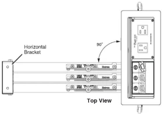
Figure 1. Retractor SM Module, Horizontal Mounting
Vertical Mounting: Ensure the Retractor SM modules hang freely without touching the floor and are not obstructed by anything under the table. The standard system requires approximately 28 inches (70 cm) from the top of the furniture to clear the floor.
Angular Mounting: Angular mounting is necessary where the enclosure size and installation location makes the Retractor SM modules too long for vertical mounting and there is not adequate under-table clearance for horizontal mounting. An additional mounting hole allows installation at an angle providing extra floor clearance (see the mounting diagrams on the next pages).
Retractor SM Cable Cubby 1200/1400 Mounting
The following diagrams indicate the required clearances under a table for proper Retractor SM installation and operation in a Cable Cubby 1200 enclosure. The side-to-side clearance dimensions are identical for the Cable Cubby 1400 enclosure.
Retractor SM Cable Cubby Mount - Quad
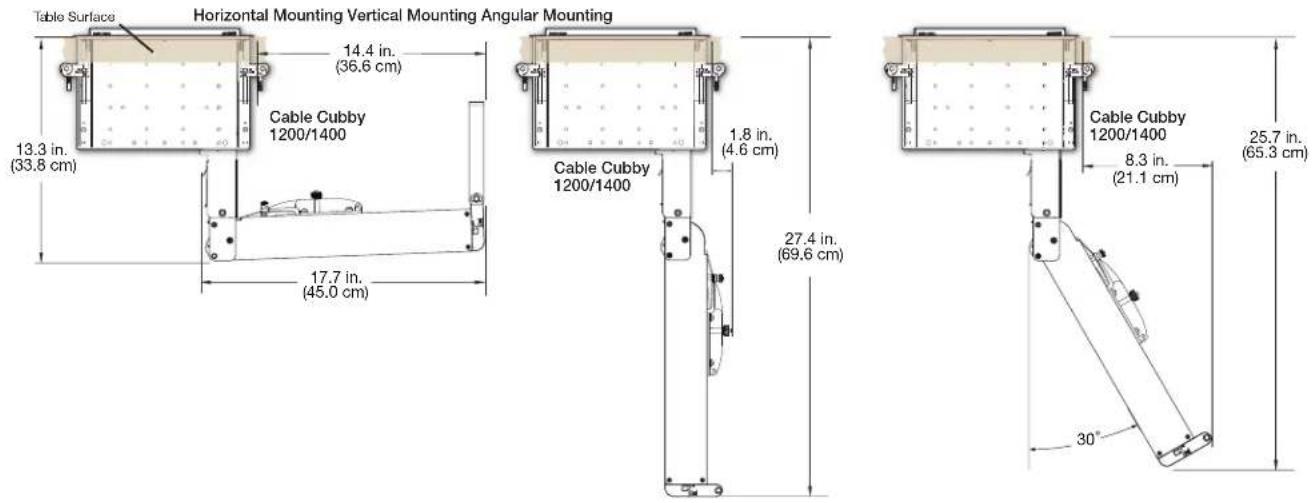
Figure 2. Cable Cubby 1200/1400 Quad Bracket Clearance
Retractor SM Cable Cubby Mount - Triple
The following diagrams indicate the required clearances under a table for proper Retractor SM installation and operation in a Cable Cubby 1200 enclosure. The front and rear clearance dimensions are identical for the Cable Cubby 1400 enclosure.
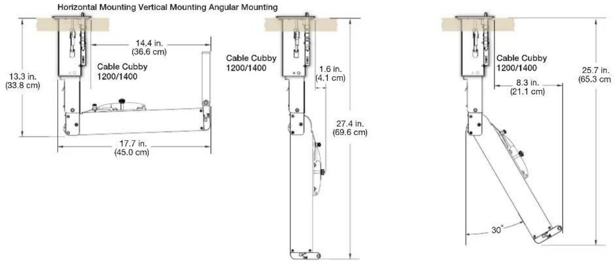
Figure 3. Cable Cubby 1200/1400 Triple Bracket Clearance
Retractor SM Cable Cubby 500/700 Mounting
The Cable Cubby 500 and Cable Cubby 700 enclosures require a Retractor SM Cable Cubby Mount - Triple for Retractor SM installation. Up to three retractors can be installed. Filler modules are required for unused retractor spaces.
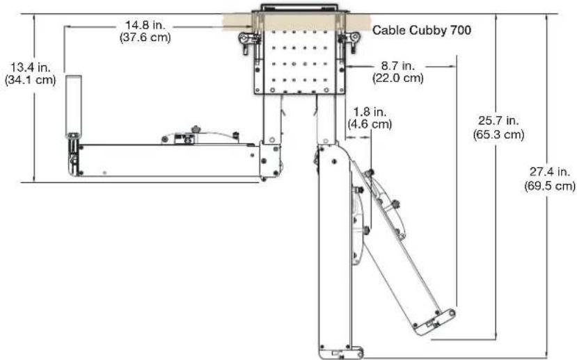
Figure 4. Cable Cubby 500 Clearance
The Cable Cubby 700 enclosure is wider; however, the clearance dimensions for the Retractor SM from each side are the same.
Pigtails
For connections to devices under the table, the Retractor SM modules have 6 feet (1.8 m) of pigtail from the exit of the cable retainer as shown below.
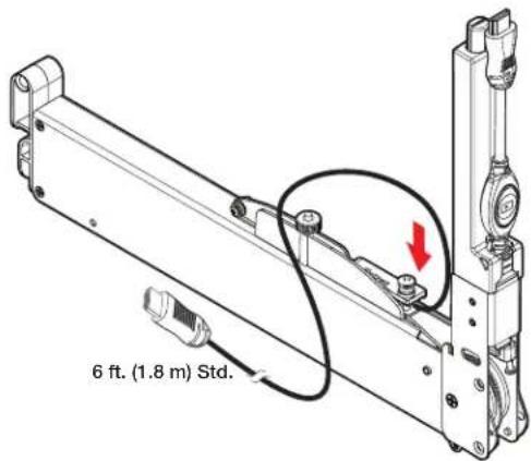
Figure 5. Retractor SM Pigtail
Prepare the Retractors
The Retractor SM modules are delivered ready to mount vertically. No further modifications are required. Confirm proper tension adjustment using the cable tension adjustment instructions on the product label. If the "Share" button is not seated fully against the cable release assembly, confirm proper tension adjustment using the instructions on the product label.
To mount a Retractor SM horizontally or at an angle:
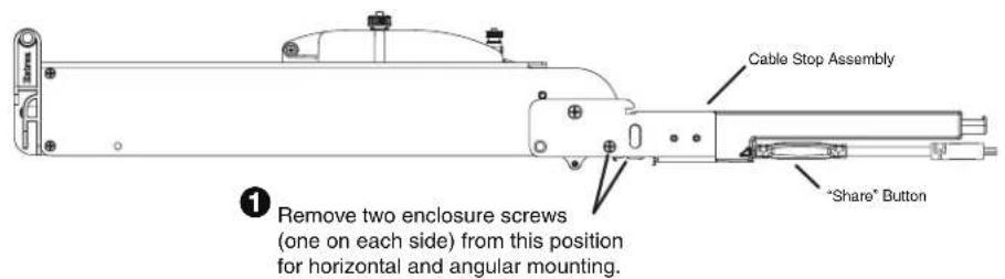
Figure 6. Retractor SM Horizontal Mounting
To mount the Retractor SM at an angled position for increased under-table clearance:
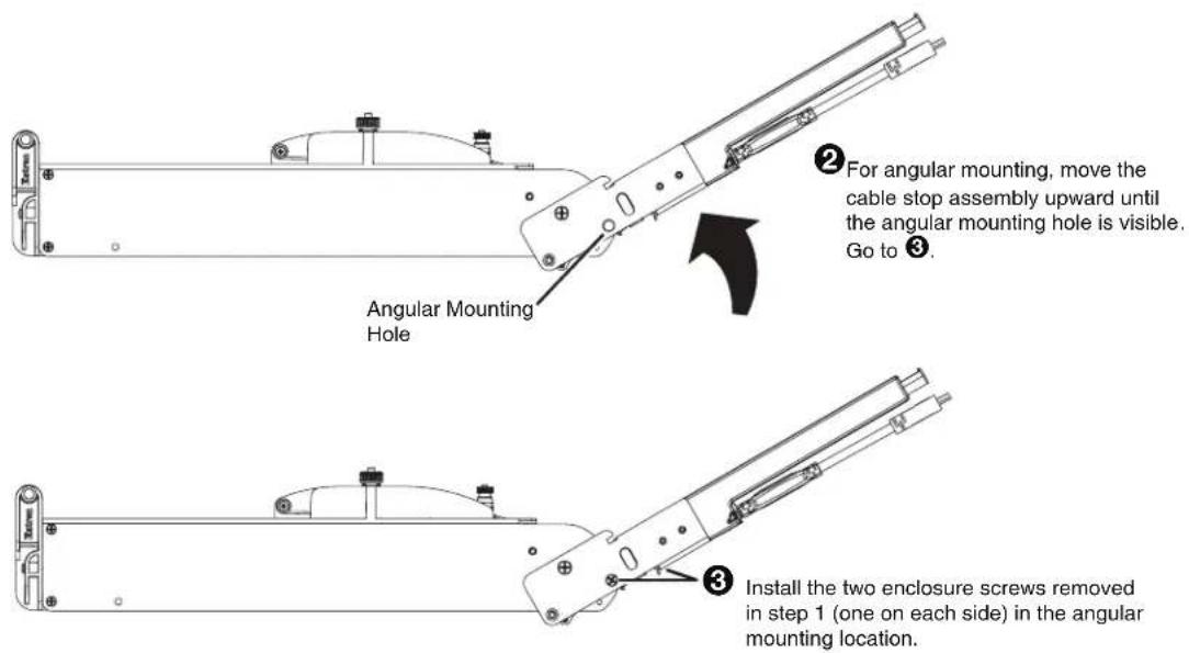
Figure 7. Retractor SM Angular Mounting
Installation
This section provides details of the retractor system installation, cable connection, and verification of operation.
• Retractor SM installation Overview
• Cable Cubby 1200 and Cable Cubby 1400 Enclosures
• Cable Cubby 500 and Cable Cubby 700 Enclosures
• Retractor SM Filler Module
• Horizontal Mounting Bracket
- Locking Screw
- Connect the Cables
- Initial Adjustments
By now you should be certain the Retractor SM modules have adequate under-table clearance for installation and that proper legroom is provided to avoid accidental contact with the system. You should have the required accessories for mounting the retraction system and to configure the enclosure (see Planning on page 3).
DANGER:
Retractor SM installation Overview
- Follow the enclosure installation guide for new installations, or prepare an existing enclosure to mount the Retractor SM modules.
- Refer to the bracket installation examples that follow, and install the Retractor SM modules.
- For horizontal mounting, proceed to Horizontal Mounting Bracket on page 14.
- For vertical and angular mounting, proceed to Locking Screw on page 15 for final installation details.
- Connect Retractor SM cables to devices under the table.
- Perform initial adjustments (see Initial Adjustments on page 16).
Cable Cubby 1200 and Cable Cubby 1400 Enclosures
To install a Retractor SM module in a Cable Cubby 1200 or Cable Cubby 1400 enclosure, a Cable Cubby Mount - Quad, or a Cable Cubby Mount - Triple is required.
Retractor SM Cable Cubby Mount - Quad
Each Quad Bracket can mount up to two Retractor SM modules on either side of a centrally located Power Module.
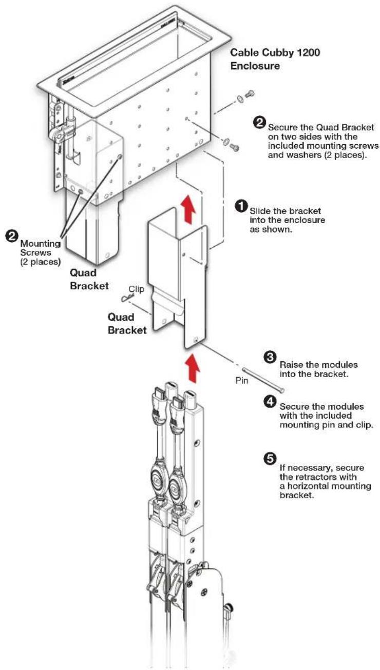
Figure 8. Retractor SM Mounting with Quad Bracket
Retractor SM Cable Cubby Mount - Triple
A Triple Bracket can mount up to three Retractor SM modules on either side of a Cable Cubby 1200 enclosure.
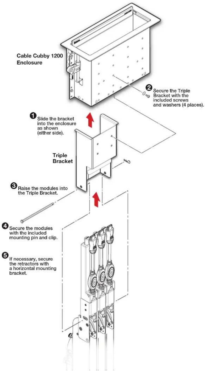
Figure 9. Retractor SM Mounting with Triple Bracket
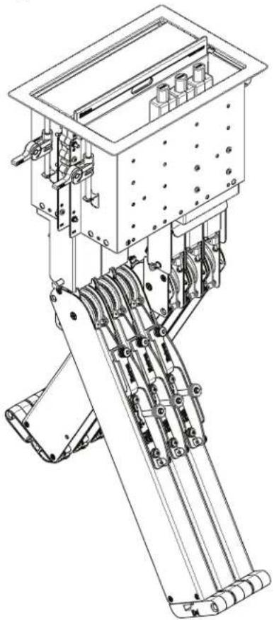
Cable Cubby 1400
Up to six Retractor SM modules can be mounted in the Cable Cubby 1400 enclosure using the Triple Brackets. Up to eight Retractor SM modules can be installed using the Quad Brackets. The brackets install in the Cable Cubby 1400 the same as in a Cable Cubby 1200. When two Triple Brackets are installed, they must be mounted diagonally and opposite as shown below.
natural_image
Technical line drawing of a mechanical device with articulated arms and mounting brackets (no text or symbols)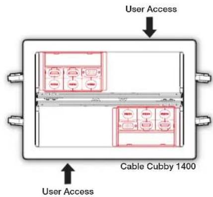
Figure 10. Multiple Retractor SM Mounted in Cable Cubby 1400
NOTE: Cable Cubby 1400 enclosures support vertical and angular mounting.
Cable Cubby 500 and Cable Cubby 700 Enclosures
The Retractor SM modules require a bracket for installation in a Cable Cubby 500 or Cable Cubby 700 enclosure. Each bracket installs up to three modules.
The enclosure must be installed and properly configured before beginning a Retractor SM module installation.
![Retractor Trim (included with the Cable Cubby enclosure) Place the Retractor Trim in the mounting position. Cable Cubby 500 Secure the trim using the provided mounting screws (2 places). [Slide clamp not shown for clarity] Align the bracket mounting holes with the enclosure holes and secure with the included screws and washers (3 places). Push the bracket up into the enclosure and against the trim. NOTE: The bracket tab must be located inside the trim. Triple Bracket Secure the modules with the included pin and clip.](/content/2026/05/991398/images/74fb24f1b8681ed06a1e7e715ca493c7d4d486b9059dec3e14f2605cab55ce80.jpg)
Figure 11. Cable Cubby 500/700 Enclosure Mounting
Retractor SM Filler Module
The Retractor SM Filler Module is required to occupy unused space in Retractor SM installations. The kit includes the filler module, a cable pass-through plate, hole plugs (for unused pass-through holes), a blank cover plate, and hardware for mounting the plates.
A blank cover plate or pass-through plate must be fastened to the Filler Module prior to it being installed in the enclosure.
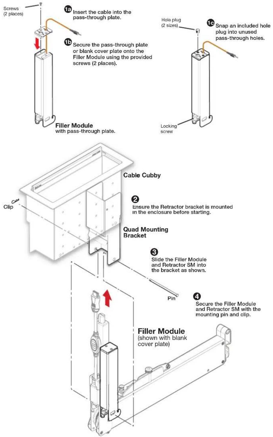
Figure 12. Retractor SM Filler Module Installation
Retractor SM • Installation 13
Horizontal Mounting Bracket
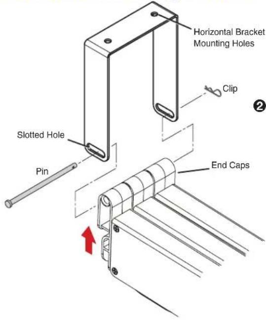

With the Retractor SM modules installed in the enclosure, attach the Horizontal Bracket to the Retractor end caps using the included pin and clip.

Raise the Retractor SM modules with attached bracket to the desired mounting location.
NOTE: Be certain the system is perpendicular to the enclosure (see the Top View Diagram on page 11) to prevent binding of the pulley system.

Ensure the bracket is flush with the surface and trace a line around the bracket perimeter.

Lower the assembly and remove the horizontal bracket from the Retractor SM modules.

Position the bracket inside the lines drawn in step 3 and fasten with the supplied screws.

Raise the Retractor SM modules up into the installed bracket, run the pin through the bracket and end caps, and secure with the supplied clip.

See Locking Screw on page 15 for final installation details.
ATTENTION:
Figure 13. Horizontal Mounting Bracket Installation
Locking Screw
A locking screw on each Retractor SM and Retractor SM Filler Module prevents it from rotating on the enclosure mounting pin during operation. Tighten each locking screw to prevent movement of the module.
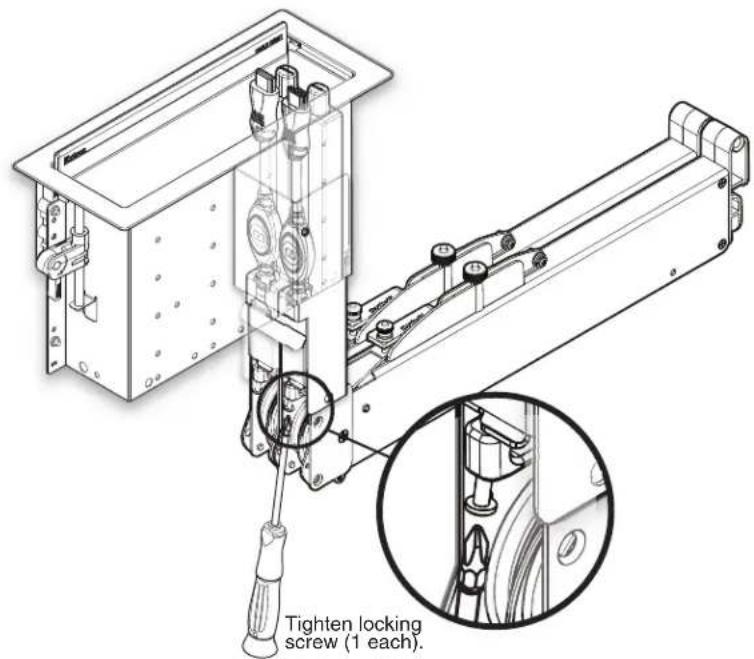
Figure 14. Locking Screw
NOTE: Do not overtighten. The locking screw only needs to be snug.
Connect the Cables
Connect the cables beneath the enclosure to the proper device.
Excess cabling may cause clearance issues. Use wire ties to secure under-table cabling to prevent accidental contact or entanglement with users.
Initial Adjustments
Once installed, proper Retractor operation must be verified and necessary adjustments performed.
CAUTION: Do not operate a Retractor until it is installed.
Confirm Proper Cable Extension
To extend a cable, grasp the connector and pull it from the Retractor to its full length.
Confirm Proper Cable Retraction
To retract a cable:
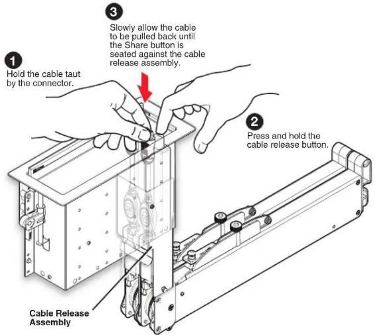
Figure 15. Confirm Cable Retraction
CAUTION: Use one hand to control the cable as it retracts. A cable allowed to retract too quickly and without control can cause possible injury to the user or damage the furniture surface, Cable Cubby, and nearby items.
- If the cable does not retract to suit your application, see the Speed Control section on page 20.
- When the Share button is seated against the cable release assembly, release the button and cable.
- If the Share button is not seated fully against the cable release assembly, confirm proper tension adjustment using the pulley system adjustment Pulley System Adjustment on page 18.
Operation
This section provides details of the retractor system operation.
- Extend a Cable
- Retract a Cable
Once installed and the initial adjustments are completed, the retractors are ready for operation.
CAUTION:
- Retraction should be a slow, controlled motion.
- Keep hands away from moving parts.
ATTENTION :
To connect a cable, grip it by the connector and pull enough cable from the retractor to connect to the device. There is no need to press the cable release button when extending a cable. When you stop pulling the cable, the cable release assembly fixes the length automatically.
Retract a Cable
- Disconnect the cable from the device.
- Press and hold the cable release button.
- When the Share button is against the cable release assembly, release the button.
Maintenance and Adjustments
• Pulley System Adjustment
- Speed Control
ATTENTION:
Pulley System Adjustment
The tension on the cable that provides constant force during cable extension and retraction is maintained by proper adjustment of the pulley system. Too little tension and the cable will have slack or may slip out of the pulley tracks, and will not retract properly.
To Adjust the Pulley System:
- Before beginning pulley system adjustments, ensure the cable routing around the pulley system is correct (see below) and the cable is completely retracted into the enclosure.
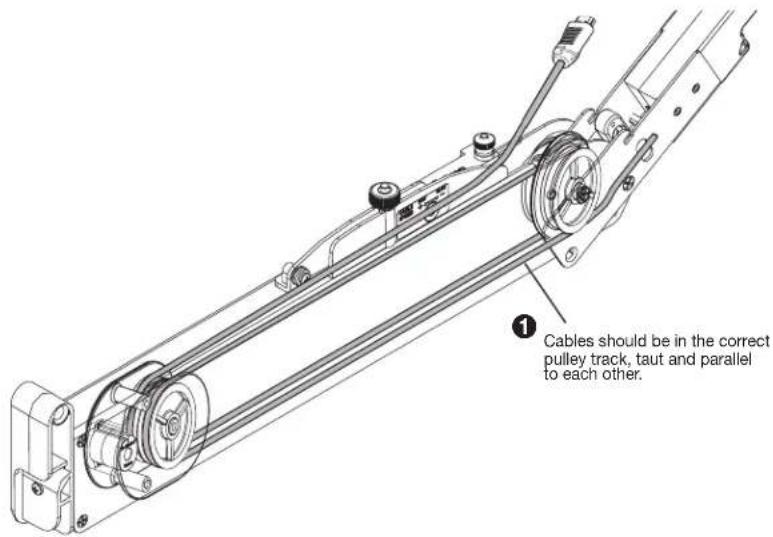
Figure 16. Cable Routing
- Hold the cable to prevent movement.
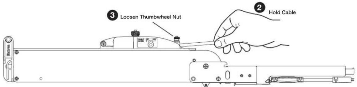
Figure 17. Thumbwheel Nut
- Turn the thumbwheel nut on the Speed Control counterclockwise to loosen it until the cable can be moved. Do not allow it complete freedom of movement.
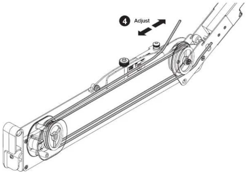
Figure 18. Pulley System Adjustment
- Adjust the cable (see figure 18) in and out to align the bottom pulley screw with the alignment port on the enclosure (see figure 19).
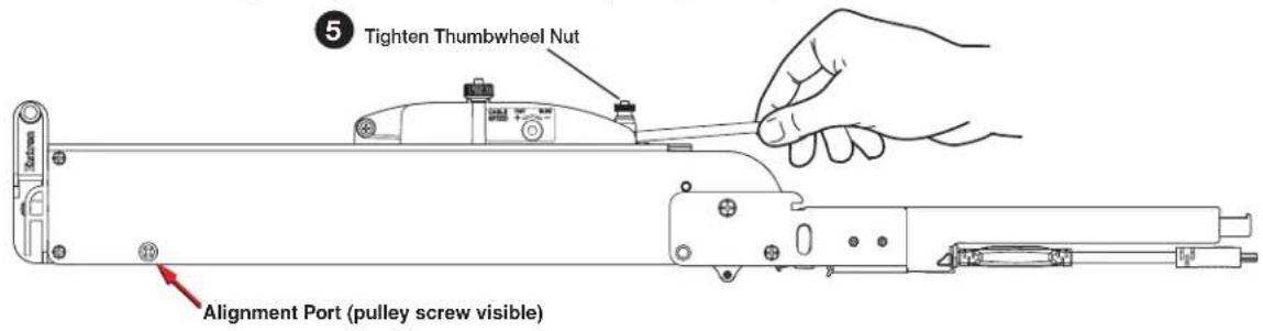
Figure 19. Pulley Alignment Port
- Turn the thumbwheel nut clockwise to tighten it and secure the cable.
Speed Control
The Retractor SM module is delivered with the speed control adjusted for nominal operation in all mounting orientations (vertical, horizontal, and angular), however, speed control adjustment can be required in your application.

Figure 20. Speed Control
NOTES:
- Ensure the speed control knob remains fully seated, with the teeth of the knob engaged throughout adjustments.
- Retraction speed is affected by the installation orientation (vertical, horizontal, or angular). Always test speed adjustments with the Retractor in its installed position.
Speed Control Coarse Adjustment
The speed control adjusts the cable retraction speed. The coarse speed control adjustment allows coarse setting of the retraction speed.
Follow the steps below until the desired retraction speed is achieved.
To Decrease Retraction Speed
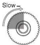
1 Rotate the speed control a quarter turn.
② Test the retraction speed after each quarter turn.
③ Repeat steps 1 and 2 until the desired retraction speed is reached.
4 See the "Speed Control Fine Adjustment" section.
To Increase Retraction Speed
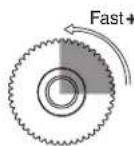
Figure 21. Speed Control, Course Adjustment
Speed Control Fine Adjustment
In most cases, coarse adjustment is all that is required to reach the desired retraction speed. Further speed adjustment in smaller increments can also be necessary. See below for fine adjustment of the retraction speed.
To Decrease Retraction Speed
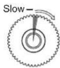
1 Turn the speed control a single "click".
② Test the retraction speed after each click.
3 Repeat steps 1 and 2 until the desired retraction speed is reached.
To Increase Retraction Speed
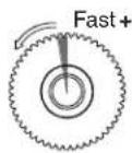
Figure 22. Speed Control, Fine Adjustment
Reference Information
• Retractor SM Part Numbers
• Optional Accessories
Retractor SM Part Numbers
Retractors are available in versions to support the TeamWork Collaboration systems. Each retractor provides cable that extends up to 3 feet (90 cm) from the enclosure.
See the website at www.extron.com for the complete line.
Optional Accessories
See the product page at www.extron.com for the complete line or Retractor SM accessories.
| Retractor SM, All Systems | |
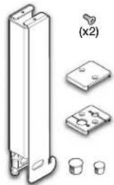 | Retractor Filler Module |
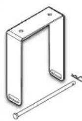 | Horizontal Mounting Bracket |
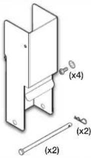 | Retractor SM Mount - Quad for the Cable Cubby 1200/1400 |
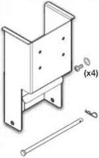 | Retractor SM Mount - Triple for the Cable Cubby 1200/1400 |
 | Retractor SM Mount - Triple for the Cable Cubby 500/700 |
Extron Warranty
Extron Electronics warrants this product against defects in materials and workmanship for a period of three years from the date of purchase. In the event of malfunction during the warranty period attributable directly to faulty workmanship and/or materials, Extron Electronics will, at its option, repair or replace said products or components, to whatever extent it shall deem necessary to restore said product to proper operating condition, provided that it is returned within the warranty period, with proof of purchase and description of malfunction to:
USA, Canada, South America, and Central America:
Extron Electronics
1230 South Lewis Street
Anaheim, CA 92805
U.S.A.
Japan:
Extron Electronics, Japan
Kyodo Building, 16 Ichibancho
Chiyoda-ku, Tokyo 102-0082
Japan
Europe and Africa:
Extron Europe
Hanzeboulevard 10
3825 PH Amersfoort
The Netherlands
China:
Extron China
686 Ronghua Road
Songjiang District
Shanghai 201611
China
Asia:
Extron Asia Pte Ltd
135 Joo Seng Road, #04-01
PM Industrial Bldg.
Singapore 368363
Singapore
Middle East:
Extron Middle East
Dubai Airport Free Zone
F13, PO Box 293666
United Arab Emirates, Dubai
This Limited Warranty does not apply if the fault has been caused by misuse, improper handling care, electrical or mechanical abuse, abnormal operating conditions, or if modifications were made to the product that were not authorized by Extron.
NOTE: If a product is defective, please call Extron and ask for an Application Engineer to receive an RA (Return Authorization) number. This will begin the repair process.
USA: 714.491.1500 or 800.633.9876
Europe: 31.33.453.4040
Asia: 65.6383.4400
Japan: 81.3.3511.7655
Units must be returned insured, with shipping charges prepaid. If not insured, you assume the risk of loss or damage during shipment. Returned units must include the serial number and a description of the problem, as well as the name of the person to contact in case there are any questions.
Extron Electronics makes no further warranties either expressed or implied with respect to the product and its quality, performance, merchantability, or fitness for any particular use. In no event will Extron Electronics be liable for direct, indirect, or consequential damages resulting from any defect in this product even if Extron Electronics has been advised of such damage.
Please note that laws vary from state to state and country to country, and that some provisions of this warranty may not apply to you.
| Extron Headquarters+1.800.633.9876 (Inside USA/Canada Only)Extron USA - West Extron USA - East+1.714.491.1500 +1.919.850.1000+1.714.491.1517 FAX +1.919.850.1001 FAX | Extron Europe+800.3987.6673(Inside Europe Only)+31.33.453.4040+31.33.453.4050 FAX | Extron Asia+65.6383.4400+65.6383.4864 FAX | Extron Japan+81.3.3511.7656+81.3.3511.7656 FAX | Extron China+86.21.3760.1568+86.21.3760.1566 FAX | Extron Middle East+971.4.299.1800+971.4.299.1880 FAX | Extron Korea+82.2.3444.1571+82.2.3444.1575 FAX | Extron India1800.3070.3777(Inside India Only)+91.80.3055.3777+91.80.3055.3737 FAX |
- Safety Instructions
- Safety Instructions • English
- Conventions Used in this Guide
- Notifications
- DANGER:
- Specifications Availability
- Extron Glossary of Terms
- Copyright
- Trademarks
- Contents
- Introduction ...... 1
- Getting Started .... 3
- Installation 8
- Operation 17
- Maintenance and Adjustments....18
- Reference Information ......21
- Introduction
- About this User Guide
- About the Retractor SM Module
- Features
- Getting Started
- Planning
- Determine Under-table Clearances
- NOTES:
- Retractor SM Cable Cubby 1200/1400 Mounting
- Retractor SM Cable Cubby Mount - Triple
- Retractor SM Cable Cubby 500/700 Mounting
- Pigtails
- Prepare the Retractors
- Installation
- Retractor SM installation Overview
- Cable Cubby 1200 and Cable Cubby 1400 Enclosures
- Retractor SM Cable Cubby Mount - Quad
- Cable Cubby 1400
- Cable Cubby 500 and Cable Cubby 700 Enclosures
- Retractor SM Filler Module
- ATTENTION:
- Locking Screw
- Connect the Cables
- Initial Adjustments
- Confirm Proper Cable Extension
- Confirm Proper Cable Retraction
- Operation
- CAUTION:
- ATTENTION :
- Retract a Cable
- Maintenance and Adjustments
- Pulley System Adjustment
- To Adjust the Pulley System:
- Speed Control
- Speed Control Coarse Adjustment
- Speed Control Fine Adjustment
- Reference Information
- Retractor SM Part Numbers
- Optional Accessories
- Extron Warranty
- USA, Canada, South America, and Central America:
- Japan:
- Europe and Africa:
- China:
- Asia:
- Middle East:
Brand : Extron
Model : Retractor SM Network
Category : Network accessory