
LA240A - Agricultural tractor KUBOTA - Free user manual and instructions
Find the device manual for free LA240A KUBOTA in PDF.


| Product Type | Front Loader |
| Brand | Kubota |
| Model | LA240A |
| Compatible Tractors | Kubota B Series (B2320, B2620, B2920, B3350) |
| Lift Capacity at Pivot Pin | 540 kg (1190 lbs) |
| Lift Capacity at 500 mm Forward | 260 kg (573 lbs) |
| Bucket Capacity | 0.2 - 0.3 m³ (varies with bucket) |
| Overall Width | 1420 mm (56 in) |
| Overall Height | 800 mm (31.5 in) |
| Weight | 230 kg (507 lbs) |
| Hydraulic Pressure | 19.6 MPa (2840 psi) |
| Hydraulic Flow | 30 L/min (7.9 GPM) |
| Cylinders | 2 lift, 1 tilt |
| Quick Attach | Yes |
| Color | Orange (Kubota standard) |
| Material | Heavy-duty steel |
| Warranty | 2 years (standard) |
| Safety Features | Safety lock, bucket level indicator |
| Maintenance | Grease fittings every 10 hours |
| Cleaning | Power wash with mild detergent |
| Storage | Store indoors, protect hydraulic hoses |
| Repairability | Parts available through Kubota dealers |
| Serial Number Location | On loader arm or frame |
Frequently Asked Questions - LA240A KUBOTA
User questions about LA240A KUBOTA
0 question about this device. Answer the ones you know or ask your own.
Ask a new question about this device
Download the instructions for your Agricultural tractor in PDF format for free! Find your manual LA240A - KUBOTA and take your electronic device back in hand. On this page are published all the documents necessary for the use of your device. LA240A by KUBOTA.
USER MANUAL LA240A KUBOTA
340: Del Amo Blvd, Torrance, CA 90506, U.S.A.
Telephone (310)870-5970
Western Division : 1175 S. Guild Ave., Locl, CA 95240
Talantura 0291334-3019
Central Division : 14855 F44 Blvd., Fort Worth, TX 76155
Talentircau : 0171571-3900
Northern Division : 5300 or One Punala Way, Gravenport, DH 43129
Talenterui 6141835-1100
Southeast Division : 1025 Northbrook Parkway, Suwano, GA 30024
电话号码:(01935-8155)
Canada : KUROTA CANADA LTD
090 14th Avenue, Mukay
Jebuynou 1938/04-2427
Telephones (33.12)
FRAKTI KUBOTA EUROPE S.A.S. 10.45 Dru Juler Housing, 71.5766.0510t Avondazil Order France
1375: H.B. James et al.
Telephone 13301-3
A EUROPE S.A.S Italy Branch
Via Grand, 25 20068 Reach
Telephone (02-51680377
Darmer Road, Thars, Oxfordshire, OX9 & NJ, UK
Telephone: (46)844214500
ATA EBRANO S.6
span : KUBOTA ESPANA S.A.
Avenida Bocomo No.5, Poligro Industrial & Laguna, Loganca, 28916 (Madrid, South)
Telephone : (34)81-506-8442
Australia : KUBOTA TRACTOR AUSTRALIA PTY LTD.
25 28 Pennas Way, Inserina, VIC 3009 Australia
Telephone: (61)5-9394-4400
Malaysia : SIME KUBOTA SDN. BHD.
No.3 Jatari Sapeda 25/123 Tamen Parodactrian Axis
Seksen 25. 40400 Shah Alam, Selangar Darul Lisan Malaysia
Telephone: 1833-738-1388
Philippines: KUBOTA PHILIPPINES, INC
155 Paray, Aucas, Smith, Irene, Thomas, 11/13 Quzon City, Houston.
Telephone: (63)2-9271
J TAIWAN AGRICULTURAL MACHINERY CO., LTD.
- Escalion, 2nd D4, Telloe Shilano Kachakran 68107, Taiwan B.O.C.
16, Pingling S&I Ha, Gm43
Indonesia: PT KUPRITA INDONESIA
- KOBUTA INDONESIA
Jalan Setyaburi 276 Semiarang, Indonesia
Telephones 18264-7472843
AM KUBOTA CORPORATION CO., LTD.
India KUBOTA AGRICULTURAL MACHINERY INDIA PVT LTD
George Laval 5 Illie, Ollamela Tosh Dark Net, \$100 Industrial Estate Gailv, Chennai ARV66 The India
Code No. K2732-7125-1
AR.F.1-1.-K
OPERATOR'S MANUAL
KUBOTA TRACTOR
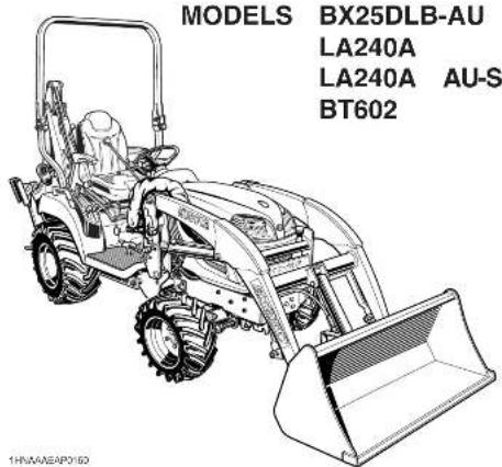
READ AND SAVE THIS MANUAL
Kubota
ABBREVIATION LIST
| Abbreviations | Definitions |
| 2WD | Two Wheel Drive |
| 4WD | Four Wheel Drive |
| API | American Petroleum Institute |
| ASABE | American Society of Agricultural and Biological Engineers, USA |
| ASTM | American Society of Testing and Materials, USA |
| DIN | Deutsches Institut für Normung, GERMANY |
| DT | Dual Traction [4WD] |
| fpm | Feet Per Minute |
| GST | Glide Shift Transmission |
| Hi-Lo | High Speed-Low Speed |
| HST | Hydrostatic Transmission |
| m/s | Meters Per Second |
| PTO | Power Take Off |
| RH/LH | Right-hand and left-hand sides are determined by facing in the direction of forward travel |
| ROPS | Roll-Over Protective Structures |
| rpm | Revolutions Per Minute |
| r/s | Revolutions Per Second |
| SAE | Society of Automotive Engineers, USA |
| SMV | Slow Moving Vehicle |
UNIVERSAL SYMBOLS
As a guide to the operation of your tractor, various universal symbols have been utilized on the instruments and controls. The symbols are shown below with an indication of their meaning.

Safety Alert Symbol

Diesel Fuel

Fuel-Level

Hourmeter/Elapsed Operating Hours

Engine Coolant-Temperature

Diesel Preheat/Glow Plugs(Low Temperature Start Aid)

Brake

Parking Brake

Battery Charging Condition

Engine Oil-Pressure

Turn Signal

Engine-Stop

Engine-Run

Starter Control

Power Take-Off Clutch Control-Off Position

Power Take-Off Clutch Control-On Position

Differential Lock

Hydraulic Control-Raised Position

Hydraulic Control-Lowered Position

3-Point Lowering Speed Control

Remote Cylinder-Retract

Remote Cylinder-Extend

Hazard Warning Lights

Headlight

Four-Wheel Drive-On

Four-Wheel Drive-Off

Fast

Slow

Read Operator's Manual

Engine Speed Control

Speed set-On

Speed set-Off

Mid-PTO

Mid-Rear-PTO

Rear-PTO
FOREWORD
You are now the proud owner of a KUBOTA Tractor. This tractor is a product of KUBOTA quality engineering and manufacturing. It is made of fine materials and under a rigid quality control system. It will give you long, satisfactory service. To obtain the best use of your tractor, please read this manual carefully. It will help you become familiar with the operation of the tractor and contains many helpful hints about tractor maintenance. It is KUBOTA's policy to utilize as quickly as possible every advance in our research. The immediate use of new techniques in the manufacture of products may cause some small parts of this manual to be outdated. KUBOTA distributors and dealers will have the most up-to-date information. Please do not hesitate to consult with them.

SAFETY FIRST
This symbol, the industry's "Safety Alert Symbol", is used throughout this manual and on labels on the machine itself to warn of the possibility of personal injury. Read these instructions carefully. It is essential that you read the instructions and safety regulations before you attempt to assemble or use this unit.

DANGER :
Indicates an imminently hazardous situation which, if not avoided, will result in death or serious injury.

WARNING :
Indicates a potentially hazardous situation which, if not avoided, could result in death or serious injury.

CAUTION :
Indicates a potentially hazardous situation which, if not avoided, may result in minor or moderate injury.
IMPORTANT :
Indicates that equipment or property damage could result if instructions are not followed.
NOTE :
Gives helpful information.
CONTENTS
SAFE OPERATION ........ -1
TRACTOR....1
LOADER 7
BACKHOE....9
SERVICING....1
SPECIFICATIONS OF THE TRACTOR 3
SPECIFICATION TABLE 3
TRAVELING SPEEDS 4
SPECIFICATIONS OF THE LOADER....5
LOADER SPECIFICATIONS 5
BUCKET SPECIFICATIONS....5
DIMENSIONAL SPECIFICATIONS 6
OPERATIONAL SPECIFICATIONS....7
LOADER TERMINOLOGY 8
SPECIFICATIONS OF THE BACKHOE 9
BACKHOE SPECIFICATIONS....9
Dimensions....9
Specifications....10
Lift Capacity (Per SAE J31)....12
BACKHOE TERMINOLOGY 13
IMPLEMENT LIMITATIONS 14
INSTRUMENT PANEL AND CONTROLS.... 16
PRE-OPERATION CHECK OF THE TRACTOR.... 18
DAILY CHECK 18
PRE-OPERATION CHECK OF THE LOADER 19
LUBRICATION 19
TRANSMISSION FLUID 19
REAR BALLAST 19
RATED OPERATING LOAD (SPILL GUARD MODEL ONLY) 21
TIRE INFLATION 22
REMOVING AIR FROM HYDRAULIC SYSTEM 22
PRE-OPERATION CHECK OF THE BACKHOE 23
Block Heater (Option)....26
STOPPING THE ENGINE....26
WARMING UP 27
Warm-up and Transmission Oil in the Low Temperature Range 27
JUMP STARTING 27
Do not Operate the Tractor at Full Speed for the First 50 Hours....28
Changing Lubricating Oil for New Tractors....28
BOARDING AND LEAVING THE TRACTOR 28
OPERATING FOLDABLE ROPS 28
To Fold the ROPS 28
To Raise the ROPS to Upright Position....29
Adjustment of Foldable ROPS.... 30
STARTING 31
Operator's Seat....31
Seat Belt 32
Head Light Switch....32
Hazard Light Switch....32
Turn Signal Light Switch....32
Brake Pedal 32
Range Gear Shift Lever (Hi-Lo).... 33
Front Wheel Drive Lever 34
Hand Throttle Lever....34
Parking Brake Pedal....34
Speed Control Pedal....35
Speed Set Device 35
STOPPING....36
Stopping....36
CHECK DURING DRIVING 36
Immediately Stop the Engine if:....36
Easy Checker(TM)....37
Fuel Gauge....37
Coolant Temperature Gauge....37
Hourmeter/Tachometer....38
PARKING 38
Parking....38
ACCESSORY 39
12V Electric Outlet 39
Glove Box 39
OPERATING TECHNIQUES 39
Differential Lock....39
Operating the Tractor on a Road....40
Operating on a Slopes and Rough Terrain....40
Transport the Tractor Safely....40
Directions for Use of Power Steering....40
REVERSING THE SEAT 41
PTO 43
PTO OPERATION....43
PTO Select Lever 43
PTO Clutch Lever 44
PTO Shaft Cover and Shaft Cap 44
Stationary PTO 44
PTO Drive Shaft 45
3-POINT HITCH & DRAWBAR 46
3-POINT HITCH 47
Attaching and detaching implements....47
Lifting Rod (Right)......47
Top Link....47
Check Chains 47
HITCH 47
Removing the 3-Point Hitch....48
Installing the 3-Point Hitch....48
HYDRAULIC UNIT 49
3-POINT HITCH CONTROL SYSTEM....49
Hydraulic Control 49
3-point Hitch Lowering Speed....49
AUXILIARY HYDRAULICS 50
Hydraulic Outlet 50
INSTALLING MOWER....51
Cutting Height Control Dial 52
Hydraulic Control Unit Use Reference Chart....53
TIRES, WHEELS AND BALLAST....54
TIRES....54
Inflation Pressure....54
Dual Tires 54
WHEEL TREAD 54
Front Wheels 54
Rear Wheels....55
BALLAST 56
Front Ballast....56
Rear Ballast 56
OPERATING THE LOADER....58
FILLING THE BUCKET 58
LIFTING THE LOAD 58
CARRYING THE LOAD 59
DUMPING THE BUCKET 59
LOWERING THE BUCKET 59
OPERATING WITH FLOAT CONTROL 59
LOADING FROM A BANK 60
PEELING AND SCRAPING 60
LOADING LOW TRUCKS OR SPREADERS FROM A PILE....61
BACKFILLING 61
HANDLING LARGE HEAVY OBJECTS....62
VALVE LOCK 62
Boom Lock (Spill guard model only).... 63
SPILL GUARD (SPILL GUARD MODEL ONLY)....64
Adjustment of spill guard link....64
ATTACHING ATTACHMENTS 65
DETACHING ATTACHMENTS 67
DISMOUNTING THE LOADER....67
ATTACHMENTS 67
Bucket....67
Pallet fork....67
ASSEMBLE PALLET FORK 68
Spoil Pile Location 71
Straight Wall or Cemetery Digging ....71
Stabilizer pads (Standard) 72
Stabilizer pads (Option) 72
TRANSPORTING....73
Driving to the Job-site....73
Trailer Transporting 73
MAINTENANCE OF THE TRACTOR 74
SERVICE INTERVALS 74
LUBRICANTS, FUEL AND COOLANT 75
PERIODIC SERVICE OF THE TRACTOR 77
HOW TO OPEN THE HOOD 77
Hood 77
Engine Cover....77
DAILY CHECK 78
Walk Around Inspection....78
Checking and Refueling....79
Checking Engine Oil Level....79
Checking Transmission Fluid Level....80
Checking Coolant Level....80
Cleaning Panel and Radiator Screen 81
Checking Brake Pedal 81
Checking Gauges, Meters and Easy Checker(TM) 81
Checking Head Light, Hazard Light etc. 81
Checking Seat Belt and ROPS.... 81
Checking and Cleaning of Electrical Wiring and Battery Cables 82
Checking Movable Parts....82
EVERY 50 HOURS....82
Lubricating Grease Fittings....82
Checking Engine Start System....83
Checking OPC System 83
Checking Wheel Bolt Torque....84
EVERY 100 HOURS 84
Battery 84
Cleaning Air Cleaner Element 86
Checking Fuel Lines and Fuel Filter 86
Adjusting Fan belt Tension 87
Adjusting HST Neutral Spring (for Speed Control Pedal)....87
Adjusting Brake Pedal 88
EVERY 200 HOURS 89
Replacing Engine Oil Filter 89
Changing Engine Oil....89
Replacing Transmission Oil Filter....90
Checking Radiator Hoses and Clamps....90
Checking Intake Air Line....91
Adjusting Toe-in....91
Checking Power Steering Line 92
EVERY 400 HOURS....92
Adjusting Front Axle Pivot....92
Changing Transmission Fluid 92
Cleaning Transmission Strainer....93
Changing Front Axle Case Oil 94
EVERY 500 HOURS....94
Replacing Fuel Filter Element....94
EVERY 800 HOURS....94
Adjusting Engine Valve Clearance 94
EVERY 1500 HOURS....94
Checking Fuel Injection Nozzle Injection Pressure....94
EVERY 3000 HOURS....94
Checking Injection Pump 94
EVERY 1 YEAR 94
Replacing Air Cleaner Element....94
EVERY 2 YEARS....94
Flushing Cooling System and Changing Coolant 94
Anti-Freeze 95
Replacing Radiator Hose (Water pipes) 96
Replacing Power Steering Hose....96
Replacing Fuel Lines 96
Replacing Engine Breather Hose 96
Replacing Intake Air Line....96
SERVICE AS REQUIRED....96
Bleeding Fuel System....96
Replacing Fuse....97
Replacing Light Bulb....97
MAINTENANCE OF THE LOADER....98
LUBRICATION 98
RE-TIGHTENING OF HARDWARE 98
Tightening Bolts and Nuts....98
DAILY CHECKS 99
EVERY 50 HOURS....99
Checking main frame bolt and nut torque....99
MAINTENANCE OF THE BACKHOE 100
DAILY CHECKS....100
LUBRICATION....101
BUCKET SERVICE....101
Changing the Backhoe Bucket ....101
Changing the Bucket Teeth 101
General torque specification....102
STORAGE OF THE TRACTOR.... 103
TRACTOR STORAGE 103
REMOVING THE TRACTOR FROM STORAGE.... 103
REMOVING THE LOADER 104
STORAGE OF THE LOADER....105
REINSTALLING THE LOADER....106
REMOVING THE BACKHOE 108
REMOVAL OF THE BACKHOE 108
STORAGE OF THE BACKHOE 110
REINSTALLING THE BACKHOE 111
TROUBLESHOOTING....113
ENGINE TROUBLESHOOTING 113
OPTIONS....114

SAFE OPERATION
TRACTOR
Careful operation is your best insurance against an accident.
Read and understand this manual carefully before operating the tractor.
All operators, no matter how much experience they may have, should read this and other related manuals before operating the tractor or any implement attached to it. It is the owner's obligation to instruct all operators in safe operation.
- Know your equipment and its limitations. Read this entire manual before attempting to start and operate the tractor.
- Pay special attention to the danger, warning and caution labels on the tractor.
- Do not operate the tractor or any implement attached to it while under the influence of alcohol, medication, controlled substances or while fatigued.
- Carefully check the vicinity before operating tractor or any implement attached to it. Do not allow any bystanders around or near tractor during operation.
- Before allowing other people to use your tractor, explain how to operate and have them read this manual before operation.
- Never wear loose, torn, or bulky clothing around tractor. It may catch on moving parts or controls, leading to the risk of an accident. Use additional safety items, e.g. hard hat, safety boots or shoes, eye and hearing protection, gloves, etc., as appropriate or required.
- Do not allow passengers to ride on any part of the tractor at anytime. The operator must remain in the tractor seat during operation.
- Check brakes, linkage pins and other mechanical parts for improper adjustment and wear. Replace worn or damaged parts promptly. Check the tightness of all nuts and bolts regularly. (For further details, see "PERIODIC SERVICE OF THE TRACTOR" section.)
- Keep your tractor clean. Dirt, grease, and trash build up may contribute to fires and lead to personal injury.
- Use only implements meeting the specifications listed under "IMPLEMENT LIMITATIONS" in this manual or implements approved by KUBOTA.
-
Use proper weights on the front or rear of the tractor to reduce the risk of upsets. When using the front loader, put an implement or ballast on the 3-point hitch to improve stability. Follow the safe operating procedures specified in the implement or attachment manual.
-
Do not modify the tractor. Unauthorized modification may affect the function of the tractor, which may result in personal injury.
◆CAB, ROPS
- KUBOTA recommends the use of a CAB or Roll Over Protective Structures (ROPS) and seat belt in almost all applications. This combination will reduce the risk of serious injury or death, should the tractor be upset. Check for overhead clearance which may interfere with a CAB or ROPS.
- Set parking brake and stop engine. Remove any obstruction that may prevent raising or folding of the ROPS. Do not allow any bystanders. Always perform function from a stable position at the rear of the tractor. Hold the top of the ROPS securely when raising or folding. Make sure all pins are installed and locked.
- If the CAB or ROPS is loosened or removed for any reason, make sure that all parts are reinstalled correctly before operating the tractor.
- Never modify or repair any structural member of a CAB or ROPS because welding, bending, drilling, grinding, or cutting may weaken the structure.
- A damaged CAB or ROPS structure must be replaced, not repaired or revised.
- If any structural member of the CAB or ROPS is damaged, replace the entire structure at your local KUBOTA Dealer.
- If the tractor is equipped with a foldable ROPS it may be temporarily folded down only when absolutely necessary for areas with height constraints.
(There is no operator protection provided by the ROPS in the folded position. For operator safety the ROPS should be placed in the upright and locked position and the seat belt fastened for all other operations.) - Always use the seat belt if the tractor has a CAB or ROPS.
Do not use the seat belt if a foldable ROPS is down or there is no ROPS. Check the seat belt regularly and replace if frayed or damaged.

(1) ROPS (2) Seat belt
Operator safety is a priority. Safe operation, specifically with respect to overturning hazards, entails understanding the equipment and environmental conditions at the time of use. Some prohibited uses which can affect overturning hazards include traveling and turning with implements and loads carried too high etc. This manual sets forth some of the obvious risks, but the list is not, and cannot be, exhaustive. It is the operator's responsibility to be alert for any equipment or environmental condition that could compromise safe operation.
Starting
-
Always sit in the operator's seat when starting engine or operating levers or controls. Adjust seat per instructions in the operating the tractor section. Never start engine while standing on the ground.
-
Before starting the engine, make sure that all levers (including auxiliary control levers) are in their neutral positions, that the parking brake is engaged, and that the Power Take-Off (PTO) is disengaged or "OFF". Fasten the seat belt if the tractor has a CAB, a fixed ROPS or a foldable ROPS in the upright and locked position.
-
Do not start engine by shorting across starter terminals or bypassing the safety start switch. Machine may start in gear and move if normal starting circuitry is bypassed.
-
Do not operate or idle engine in a non-ventilated area. Carbon monoxide gas is colorless, odorless, and deadly.
-
Check before each use that operator presence controls are functioning correctly. Test safety systems. (See "Checking Engine Start System" and "Checking OPC System" in "EVERY 50 HOURS" in "PERIODIC SERVICE OF THE TRACTOR" section.)
Do not operate unless they are functioning correctly.
◆Working
- Pull only from the hitch. Never hitch to axle housing or any other point except hitch; such arrangements will increase the risk of serious personal injury or death due to a tractor upset.

(1) Hitch
-
Keep all shields and guards in place. Replace any that are missing or damaged.
-
Avoid sudden starts. To avoid upsets, slow down when turning, on uneven ground, and before stopping.
-
The tractor cannot turn with the differential locked and attempting to do so could be dangerous.
-
Do not operate near ditches, holes, embankments, or other ground surface features which may collapse under the tractor's weight. The risk of tractor upset is even higher when the ground is loose or wet. Tall grass can hide obstacles, walk the area first to be sure.
-
Watch where you are going at all times. Watch for and avoid obstacles. Be alert at row ends, near trees, and other obstructions.
-
When working in groups, always let the others know what you are going to do before you do it.
-
Never try to get on or off a moving tractor.
-
Always sit in the operator's seat when operating levers or controls.
-
Do not stand between tractor and implement or trailed vehicle unless parking brake is applied.
◆Safety for children
Tragedy can occur if the operator is not alert to the presence of children. Children generally are attracted to machines and the work they do.
-
Never assume that children will remain where you last saw them.
-
Keep children out of the work area and under the watchful eye of another responsible adult.
-
Be alert and shut your machine down if children enter the work area.
-
Never carry children on your machine. There is no safe place for them to ride. They may fall off and be run over or interfere with your control of the machine.
-
Never allow children to operate the machine even under adult supervision.
-
Never allow children to play on the machine or on the implement.
-
Use extra caution when backing up. Look behind and down to make sure area is clear before moving.
◆Operating on slopes
Slopes are a major factor related to loss-of-control and tip-over accidents, which can result in severe injury or death. All slopes require extra caution.
-
To avoid upsets, always back up steep slopes. If you cannot back up the slope or if you feel uneasy on it, do not operate on it. Stay off slopes too steep for safe operation.
-
Driving forward out of a ditch, mired condition or up a steep slope increases the risk of a tractor to be upset backward. Always back out of these situations. Extra caution is required with 4-wheel drive models because their increased traction can give the operator false confidence in the tractor's ability to climb slopes.
-
Keep all movement on slopes slow and gradual. Do not make sudden changes in speed, direction or apply brake and make sudden motions of the steering wheel.
-
Avoid changing gears speed when climbing or going down a slope. If on a slope changing gears to neutral could cause loss of control.
-
Special attention should be made to the weight and location of implements and loads as such will affect the stability of the tractor.
-
To improve stability on slope, follow recommendations for proper ballasting as shown in "BALLAST" section.
◆Driving the tractor on the road
-
Check the front wheel engagement. The braking characteristics are different between 2 and 4-wheel drive. Be aware of the difference and use carefully.
-
Always slow the tractor down before turning. Turning at high speed may tip the tractor over.
-
On public roads use the hazard lights, if required by local traffic and safety regulations.
-
Observe all local traffic and safety regulations.
-
Turn the headlights on.
-
Drive at speeds that allow you to maintain control at all times.
-
Do not apply the differential lock while traveling at road speeds. The tractor may run out of control.
-
Avoid sudden motions of the steering wheel as they can lead to a dangerous loss of stability. The risk is especially great when the tractor is traveling at road speeds.
-
Keep the ROPS in the "UP" position and wear the seat belt when driving the tractor on the road. Otherwise, you will not be protected in the event of a tractor roll-over.
-
Do not operate an implement while the tractor is on the road. Lock the 3-point hitch in the raised position.
-
Set the implement lowering speed knob in the "LOCK" position to hold the implement in the raised position.
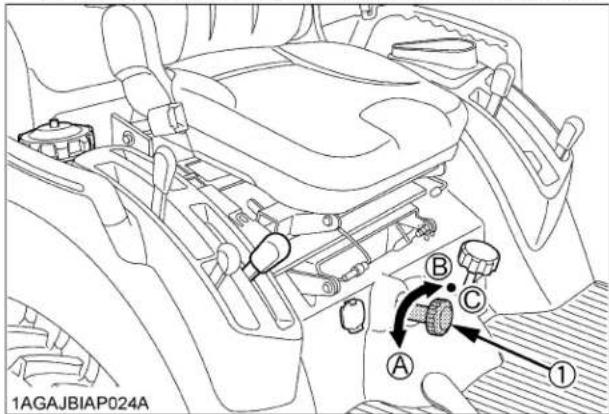
(1) 3-point hitch lowering speed knob (A) "FAST"
(B) "SLOW"
(C) "LOCK"
3. PARKING THE TRACTOR
- Disengage the PTO, lower all implements to the ground, place all control levers in their neutral positions, set the parking brake, stop the engine, remove the key from the ignition and lock the cab door (if equipped). Leaving transmission in gear with the engine stopped will not prevent tractor from rolling.
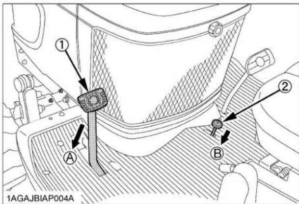
(1) Brake pedal
(A) "DEPRESS"
(B) "PUSH DOWN (2) WHILE DEPRESSING (1)"
(2) Parking brake pedal
-
Make sure that the tractor has come to a complete stop before dismounting.
-
Avoid parking on steep slopes, if at all possible park on a firm and level surface; if not, park across a slope with chock the wheels.
Failure to comply with this warning may allow the tractor to move and could cause injury or death.
- When parking your machine if at all possible park on a firm, flat and level surface; if not, park across a slope. Set the parking brake(s), lower the implements to the ground, remove the key from the ignition and lock the cab door (if equipped) and chock the wheels.
- Wait until all moving components have completely stopped before getting off the tractor, connecting, disconnecting, adjusting, cleaning, or servicing any PTO driven equipment.
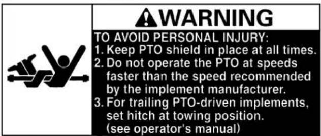
- Keep the PTO shaft cover in place at all times. Replace the PTO shaft cap when the shaft is not in use.

(1) PTO Shaft cover
(A) "NORMAL POSITION"
(2) PTO Shaft cap
(B) "RAISED POSITION"
- Before installing or using PTO driven equipment, read the manufacturer's manual and review the safety labels attached to the equipment.
- When operating stationary PTO driven equipment, always apply the tractor parking brake and place chocks behind and in front of the rear wheels. Stay clear of all rotating parts. Never step over rotating parts.
5. USING 3-POINT HITCH
- Use the 3-point hitch only with equipment designed for 3-point hitch usage.
- When using a 3-point hitch mounted implement, be sure to install the proper counterbalance weight on the front of the tractor.
- When transporting on the road, set the implement lowering speed knob in the "LOCK" position to hold the implement in the raised position.

(1) 3-point hitch lowering speed knob (A) "FAST"
(B) "SLOW"
(C) "LOCK"
- To avoid injury from separation: Do not extend lift rod beyond the groove on the threaded rod.

(1) Groove
6. SERVICING THE TRACTOR
Before servicing the tractor, park it on a firm, flat and level surface, set the parking brake, lower all implements to the ground, place the gear shift lever in neutral, stop the engine and remove the key.
- Allow the tractor time to cool off before working on or near the engine, muffler, radiator, etc.
- Do not remove radiator cap while coolant is hot. When cool, slowly rotate cap to the first stop and allow sufficient time for excess pressure to escape before removing the cap completely. If the tractor has a coolant recovery tank, add coolant or water to the tank, not the radiator. (See "Checking Coolant Level" in "DAILY CHECK" in "PERIODIC SERVICE OF THE TRACTOR" section.)
- Always stop the engine before refueling. Avoid spills and overfilling.
- Do not smoke when working around battery or when refueling. Keep all sparks and flames away from battery and fuel tank. The battery presents an explosive hazard, because it gives off hydrogen and oxygen especially when recharging.
- Before "jump starting" a dead battery, read and follow all of the instructions. (See "JUMP STARTING" in "OPERATING THE ENGINE" section.)
- Keep first aid kit and fire extinguisher handy at all times.
- Disconnect the battery's ground cable before working on or near electric components.
- To avoid the possibility of battery explosion, do not use or charge the refillable type battery if the fluid level is below the LOWER (lower limit level) mark. Check the fluid level regularly and add distilled water as required so that the fluid level is between the UPPER and LOWER levels.
- To avoid sparks from an accidental short circuit, always disconnect the battery's ground cable (-) first and reconnect it last.

(1) Battery
- Do not attempt to mount a tire on a rim. This should be done by a qualified person with the proper equipment.
- Always maintain the correct tire pressure. Do not inflate tires above the recommended pressure shown in the operator's manual.

natural_image
Illustration of a person running with a large gear and light rays, symbolizing industrial or mechanical impact (no text or symbols)- Securely support the tractor when either changing wheels or adjusting the wheel tread width.
- Make sure that wheel bolts have been tightened to the specified torque.
- Do not work under any hydraulically supported devices. They can settle, suddenly leak down, or be accidentally lowered. If it is necessary to work under tractor or any machine elements for servicing or adjustment, securely support them with stands or suitable blocking beforehand.
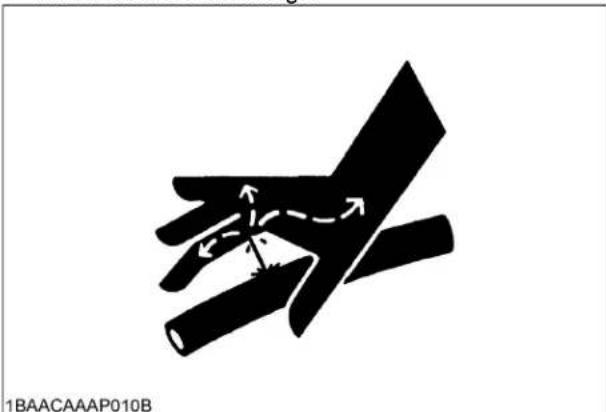
- Escaping hydraulic fluid under pressure has sufficient force to penetrate skin, causing serious personal injury. Before disconnecting hydraulic lines, be sure to release all residual pressure. Before applying pressure to the hydraulic system, make sure that all connections are tight and that all lines, pipes, and hoses are free of damage.
natural_image
Diagram of a hand holding a tool with directional arrows indicating movement or force (no text or symbols)- Fluid escaping from pinholes may be invisible. Do not use hands to search for suspected leaks; use a piece of cardboard or wood. Use of safety goggles or other eye protection is also highly recommended. If injured by escaping fluid, see a medical doctor at once. This fluid will produce gangrene or severe allergic reaction.
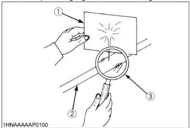
(1) Cardboard
(2) Hydraulic line
(3) Magnifying glass
- Waste products such as used oil, fuel, hydraulic fluid, and batteries, can harm the environment, people, pets and wildlife. Please dispose properly. See your local Recycling Center or KUBOTA Dealer to learn how to recycle or get rid of waste products.
LOADER
Most loader equipment accidents can be avoided by following simple safety precautions. These safety precautions, if followed at all times, will help you operate your loader safely
- Read and understand all instructions and precautions found in both the tractor and the loader operator's manuals before using the loader.
Lack of knowledge can lead to accidents.
-
It is the owner's responsibility to ensure that anyone who will operate the loader reads this manual first and becomes familiar with the safe operation of the loader.
-
For your safety, a ROPS with a seat belt is strongly recommended by KUBOTA in almost all applications. If your tractor has a foldable ROPS, fold it down only when absolutely necessary and raise it up and lock it again as soon as possible. Do not wear the seat belt when a foldable ROPS is down or a fixed ROPS is removed. If you have any questions, consult your local KUBOTA dealer.
Always use the seat belt when the tractor is equipped with a ROPS. Never use the seat belt when the tractor is not equipped with a ROPS.
- Visually check for hydraulic leaks and broken, missing, or malfunctioning parts.
Make necessary repairs before operating.
-
Replace damaged or illegible safety labels. See following pages for required labels.
-
When the front loader is mounted on the tractor, enter and exit the operator's seat only from left side of the tractor.
-
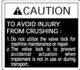
Engage the loader control valve lock to prevent accidental actuation when the implement is not in use or during transport. Do not utilize the valve lock for machine maintenance or repair.
-
Assemble, remove and reinstall the loader only as directed in this manual. Failure to do this could result in serious personal injury or death.
-
Check that all nuts, bolts, and pins are properly fitted and tightened to specification.
-
Ensure that the approved counterweight and tires are fitted to the tractor.
-
Remove mid mount mower deck (if fitted) before operating the loader.
-
Operate the loader only when properly seated at the controls. Do not operate from the ground.
-
Move and turn the tractor at low speeds. (less than 10 km/h)
-
Never allow anyone to get under the loader bucket or reach through the boom when the bucket is raised.
-
Keep children, others and livestock away when operating loader and tractor.
-
Do not walk or work under a raised loader bucket or attachment unless it is securely blocked and held in position.
-
For tractor stability and operator safety, a counter weight of the recommended size must be added to the 3-point hitch when using loader.
-
To increase stability adjust the rear wheels to the widest setting that is suitable for your application.
-
Exercise extra caution when operating the loader with a raised bucket or attachment.
-
Do not lift or carry any person on the loader, in the bucket, or other attachment.
-
Avoid loose fill, rocks and holes. They can be dangerous for loader operation or movement.
-
Avoid overhead wires and obstacles when the loader is raised. Contacting electric lines can cause electrocution.
-
Gradually stop the loader boom when lowering or lifting.
-
Use caution when handling loose or shiftable loads.
-
Using loaders for handling large, heavy, or shiftable objects is not recommended without proper handling attachments.
-
Handling large heavy objects can be extremely dangerous due to :
● Danger of rolling the tractor over.
● Danger of upending the tractor.
● Danger of the object rolling or sliding down the loader boom onto the operator.
-
If you must perform this sort of work (item 15), protect yourself by :
-
Never lift the load higher than necessary to clear the ground.
- Ensure that the Rated Operating Load is not exceeded.
● Always use the recommended counter weight. - Never lift large objects with equipment that may permit them to roll back onto the operator.
-
Move slowly and carefully, avoiding rough terrain.
-
Never lift or pull a load from any point on the loader with a chain, rope, or cable. Doing so could cause a rollover or serious damage to the loader.
-
Be extra careful when operating the tractor on a slope, always operate up and down, never across the slope. Do not operate on steep slopes or unstable surfaces.
- When operating another implement on a hillside, be sure to remove the loader to reduce the risk of rollover.
- Carry loader boom at a low position during transport. (You should be able to see over the bucket.)
- Allow for the loader length when making turns.
3. AFTER OPERATING THE LOADER
- When loader work is complete and parking or storing, choose flat and hard ground. Lower the loader boom to the ground, stop the engine, set the brakes and remove the key before leaving the tractor seat.
- Make sure the detached loader is on stands and on a hard, level surface.
- Before disconnecting hydraulic lines, relieve all hydraulic pressure by moving the controls.
- Do not remove the loader from the tractor without an approved bucket attached.
4. SERVICING THE LOADER
- Always wear safety goggles when servicing or repairing the machine.
- Do not modify the loader. Unauthorized modification may affect the function of the loader, which may result in personal injury.
- Do not use the loader as a work platform or a jack to support the tractor for servicing or maintenance.
Securely support the tractor or any machine elements with stands or suitable blocking before working underneath.
For your safety, do not work under any hydraulically supported devices. They can settle or suddenly leak down or be accidentally lowered. - Escaping hydraulic oil under pressure can have sufficient force to penetrate the skin, causing serious personal injury. Do not use hands to search for suspected leaks. If injured by escaping fluid, obtain medical treatment immediately.
- Do not tamper with the relief valve setting. The relief valve is pre-set at the factory. Changing the setting can cause overloading of the loader and tractor which may result in serious personal injury.
- When servicing or replacing pins in cylinder ends, bucket, etc., always use a brass drift and hammer. Failure to do so could result in injury from flying metal fragments.
BACKHOE
Most backhoe equipment accidents can be avoided by following simple safety precautions.
These safety precautions, if followed at all times, will help you operate your backhoe safely.
- Read and understand all precautions in this manual before service or operation. Allow only trained personnel to operate or service this equipment.
- It is the owner's responsibility to ensure that anyone who will operate the backhoe reads this manual first and becomes familiar with the safe operation of the backhoe.
- For safe operation, check the mounting bolts for tightness and that the mount levers are in the right position before operation.
- Never operate tractor with backhoe attached and loader removed.
- Check for buried material such as electrical, telephone, gas and water lines. When in doubt, contact local utility companies for their buried location prior to operating the backhoe.
- Replace any safety decal that becomes damaged, lost or illegible. Also renew all decals when repainting.
- Do not allow anyone other than the operator on the unit while in operation or transport.
- Keep all person and animals away from swing area of backhoe.
- Use care when operating on slopes to avoid tip-over. Travel at a speed compatible with safe operation, especially when operating on uneven terrain, crossing ditches or while turning.
- Operate the backhoe from the backhoe operator's seat only.
- When using on slopes, one stabilizer may be lower than the other. Use extreme care during excavation as risk of tip-over will increase.
- To reduce the risk of tip-over on a slope, place the spoil to the high side of the excavation.
- Do not dig under the stabilizer or tractor, especially in soft or sandy condition. Take extra precaution in wet or thawing ground.
These conditions can become unstable and may collapse under the weight of the machine and may cause tip over. - Never operate the machine or any equipment while under the influence of alcohol or other drugs, or while fatigued.
- When leaving the machine unattended, be sure to lower the backhoe to the ground. Set the parking brake, then shut the engine off and remove the key.
3. DRIVING THE TRACTOR ON THE ROAD
- Raise and center the boom, close the dipperstick, curl the bucket and engage the boom and swing locks before transporting the machine.
- Check the local codes or regulations that may apply to tractor / loader / backhoe operation on public streets or highways, before transporting or traveling. Use SMV emblem and warning flashers as required.
(SMV : Slow Moving Vehicle)
4. SERVICING THE BACKHOE
- Before disconnecting hydraulic lines, relieve all hydraulic pressure by moving the controls.
- Always use personal protection device such as safety goggles and ear protection when servicing or repairing the machine.
- Lower the backhoe to the ground and shut the engine off before servicing.
- When servicing or repairing pins in cylinder ends, bucket, etc., always use a brass drift and hammer. Failure to do so could result in injury from flying metal fragments.
- To avoid serious personal injury, keep clear of working area of the backhoe.
- When servicing or checking underneath, do not get under the machine while it is being held with only the bucket, backhoe or stabilizers. Securely support with jack stands.
- For your safety, do not work under any hydraulically supported machine elements. They can settle, suddenly leak down, or be accidentally lowered.
- Escaping hydraulic fluid under pressure can have sufficient force to penetrate the skin, causing serious personal injury. Before applying pressure to the system, be sure that all connections are tight and that lines, pipes and hoses are not damaged. Fluid escaping from a very small hole can be almost invisible. Do not use hands to search for suspected leaks, use a piece of cardboard or wood. If injured by escaping fluid, see a doctor at once. Serious infection or allergic reaction will develop if proper medical treatment is not administered immediately.
- Do not tamper with any backhoe control valve relief pressure setting. The relief valve pressure is preset at the factory. Changing the setting can cause overloading of the backhoe and the tractor, and serious personal injury or death may result.
- Do not modify the backhoe for any reason. Modifying the backhoe can cause an unstable condition of the tractor / loader / backhoe combination and serious personal injury or death may result.
DANGER, WARNING AND CAUTION LABELS OF THE TRACTOR
(1) Part No. K2561-6548-2
CAUTION
TO AVOID PERSONAL INJURY:
-
Read and understand the operator's manual before operation.
-
Before starting the engine, make sure that everyone is at
a safe distance from the tractor and that the PTO is OFF.
-
Do not allow passengers on the tractor at any time.
-
Before allowing other people to use the tractor, have them
read the operator's manual.
-
Check the tightness of all nuts and bolts regularly.
-
Keep all shields in place and stay away from all moving parts.
-
Slow down for turns, or rough roads.
-
On public roads use SMV emblem and hazard lights, if required
by local traffic and safety regulations.
9.Pull only from the hitch.
- Before dismounting lower the implement to the ground, set the
parking brake, stop the engine and remove the key.
- Securely support tractor and implements before working underneath.
1AGAJAXAP042E
(3) Part No. K2561-6552-2
Do not put hands
under the rear fender.
WARNING

TO AVOID PERSONAL INJURY:
KEEP HANDS AWAY FROM
PINCH POINTS OF LIFT ARMS.
(4) Part No. K1272-6585-2
Diesel fuel No fire
only


ULTRA LOW SULFUR
DIESEL FUEL ONLY
1BDAHAOAP002A
(2) Part No. K2591-6564-2
WARNING
Never modify or repair a ROPS because welding, grinding, drilling or cutting any portion may weaken the structure.
CAUTION
TO AVOID PERSONAL INJURY WHEN RAISING OR FOLDING ROPS:
- Set parking brake and stop engine.
- Remove any obstruction that may prevent raising or folding of the ROPS.
- Do not allow any bystanders.
- Always perform function from a stable position at the rear of the tractor.
- Hold the top of the ROPS securely when raising or folding.
- Make sure all pins are installed and locked.
1HNAAACAP013E
1AGAJAXAP047E
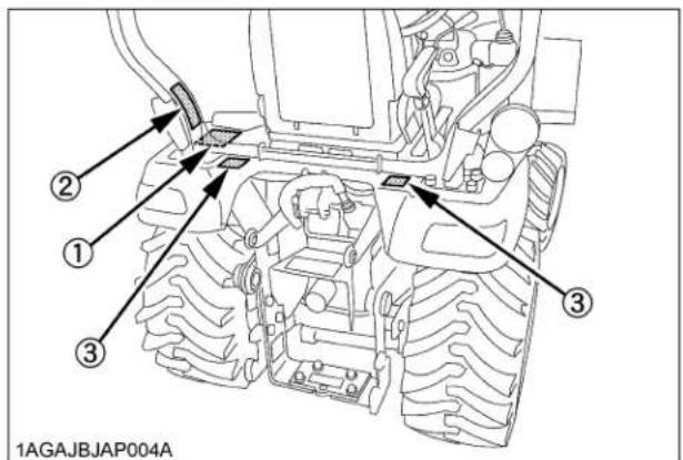
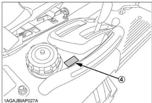
(1) Part No. K2581-6554-1
1AGAJAXAP044E
(3) Part No. K2581-6556-1

(4) Part No. K2581-6555-1

1AGAJAXAP043E
(2) Part No. K2591-6557-2

1HNAAACAP014E
(5) Part No. K2651-6568-1

1AYAACAAP1000

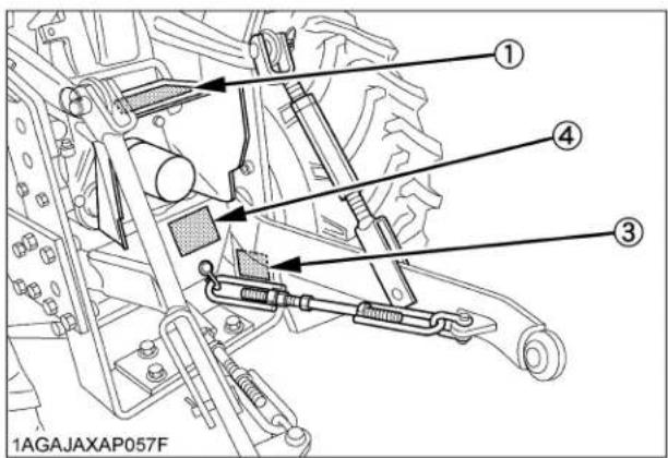

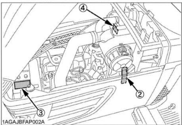
(1) Part No. K2581-6541-1


DANGER
TO AVOID POSSIBLE INJURY OR DEATH FROM A MACHINE RUNAWAY:
- Do not start engine by shorting across starter terminals or bypassing the safety start switch. Machine may start in gear and move if normal starting circuitry is bypassed.
- Start engine only from operator's seat with transmission and PTO OFF. Never start engine while standing on the ground.
1AGAJAXAP048E
(3) Part No. K2581-6542-1 Do not touch hot surface like muffler, etc.

1AGAJAXAP050E
(4) Part No. K2581-6543-1 Stay clear of engine fan and fanbelt.
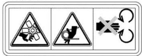
1AGAJAXAP052E
(2) Part No. K2581-6547-1 Stay clear of engine fan and fanbelt.

1AGAJAXAP049E
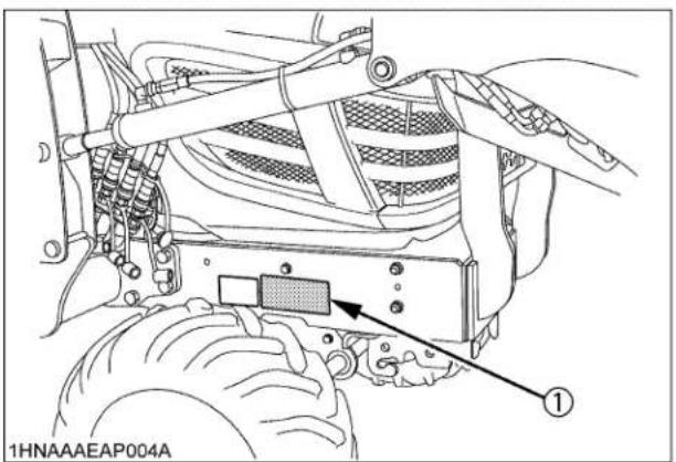
(1) Part No. K1221-6118-1

1BDAFAIAP136A

DANGER, WARNING AND CAUTION LABELS OF THE LOADER
(1) Part No. 7J246-5645-1
CAUTION
TO AVOID PERSONAL INJURY :
- Observe safety precautions in loader and tractor Operator's Manual.
- Operate the loader from tractor seat only.
- Keep children, others and livestock away when operating loader and tractor.
- Avoid holes, loose ground, and rocks which may cause tractor / loader to tip.
- Make sure approved bucket is attached before removing loader from tractor.
- When parking or storing, choose flat and hard ground. Lower the bucket to the ground, set brakes and remove key before leaving tractor.
- Before disconnecting hydraulic lines, relieve all hydraulic pressure.
1AIABAHAP019A
(5) Part No. 7J246-5644-2
WARNING

TO AVOID INJURY FROM FALLS OR BEING CRUSHED :
- DO NOT stand or work under raised loader or bucket.
- DO NOT use loader as jack for servicing.
- DO NOT use loader as a work platform.
- NEVER connect chain, cable or rope to loader bucket while operating loader.
1AIABAHAP020A
(2) Part No. 7J802-5848-1 (Spill guard model only)
natural_image
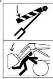
Two black-and-white illustrations showing a person using a heavy load to lift a vehicle, with no text or symbols present.▲WARNING
Install cylinder locks before performing maintenance under raised loader arms. Failure to comply could result in death or serious injury.
● Empty loader bucket and place in dump position, raise boom until boom lock channel can be positioned on cylinder rod, then stop engine.
- Pull pin and lower boom lock onto the cylindr rod, then insert pin into the hole of lower right corner of boom lock.
- Slowly lower boom until boom is stopped.
1HNADAAAP0120
(3) Part No. 7J266-5649-2
1AIABACAP077A
(6) Part No. 7J615-5633-1 (Spill guard model only)

1AIABEJAP018E
(4) Part No. 7J625-5637-1 (Spill guard model only)

WARNING
-DO NOT EXCEED ROL.
-DO NOT OPERATE LOADER WITHOUT
COUNTERWEIGHT OR BACKHOE
-DO NOT EXCEED 10KM/H
WHEN TRAVELLING WITH LOAD.
-ROL ISCALCULATED WITH
STANDARD BUCKET.OPTIONAL
ATTACHMENTS (4IN1 BUCKET ETC)
WILLREDUCETHEROL
1HNAAAEAP017A

*The labels (2), (4) are attached to the inside of the boom.
DANGER, WARNING AND CAUTION LABELS OF THE BACKHOE
(1) Part No. 75597-7528-1
WARNING
TO AVOID PERSONAL INJURY: WHEN MOUNTING AND DISMOUNTING THE BACKHOE.
- When starting the engine, always sit in the operator's seat.
- When getting off the tractor, make sure that PTO lever is off and range gear shift lever is in neutral. Then set the parking brake.
- Keep hands, feet and body from between tractor and backhoe. Never allow any part of body under the machine.
1HNAAACAP008E
(2) Part No. 75595-7517-2

1HNAAACAP011E
WARNING
TO AVOID PERSONAL INJURY:
STAY CLEAR OF OPERATING AREA OF THE BACKHOE.
(3) Part No. 75595-7524-2
WARNING

natural_image
Silhouette of a person using a tool to lift or press a piece of material (no text or symbols)TO AVOID PERSONAL INJURY:
KEEP BOTH FEET ON FOOT PLATFORM AND AWAY FROM STABILIZER.
1HNAAACAP012E
(4) Part No. 7K501-7529-1
SWING LOCK PIN

WARNING
TO AVOID PERSONAL INJURY: Set the swing lock pin, and lower the boom to the ground when leaving the operator's seat.
(5) Part No. 75597-7517-2

natural_image
Abstract black icon of a human hand holding a device (no text or symbols)1HNAAACAP010E
DANGER
TO AVOID SERIOUS CRUSHING INJURY OR DEATH: MAKE SURE BOOM SWING LOCK PIN IS INSTALLED FROM OPERATORS SEAT BEFORE ENTERING THIS AREA.
1AJABAEAP028A
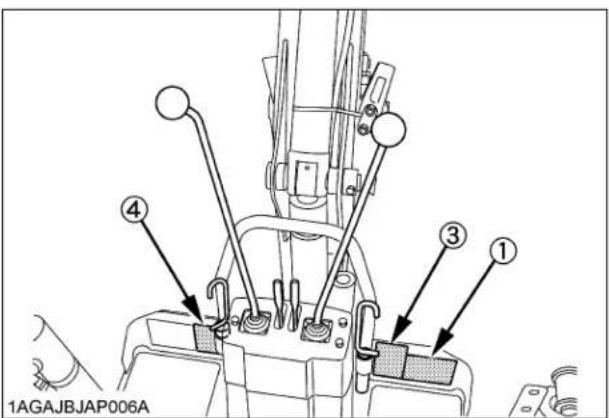

DANGER, WARNING AND CAUTION LABELS OF THE ATTACHMENTS
[LA243A AU-SG QUICK COUPLER] (Option for LA240A AU-SG)
[BX6315 QUICK COUPLER] (Option for LA240A)

(1) Part No. 7J619-3616-1

CAUTION
TO AVOID MACHINE DAMAGE OR PERSONAL INJURY 1. LOCKPINS AND SNAPPER PINS MUST BE PROPERLY INSTALLED BEFORE MOVING THE IMPLEMENT. 2. KEEP LOCKPINS AND SNAPPER PINS IN THE QUICK HITCH FRAME AT ALL TIMES.
1AGAJBJAP044E
[BX6314 PALLET FORK] (Option for LA240A, LA240 AU-SG)
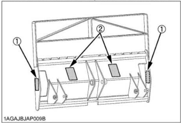
(1) Part No. 7J246-5643-1

(2) Part No. 7J612-3923-1


1AIABAHAP016A
TO AVOID PERSONAL INJURY OR DEATH CAUSED BY ROLLOVER
- Do not exceed rated load listed above. - Use rear implement and tire ballast recommended in loader operator's manual. - Operate tractor slowly taking special care when turning.
1AGAJBJAP035E
[BX6316 MECHANICAL THUMB] (Option for BT602)
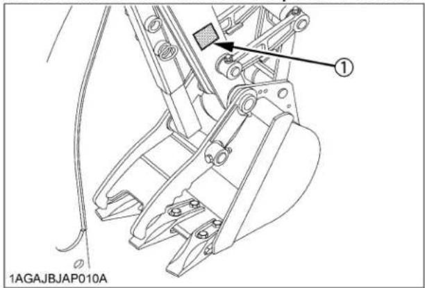
(1) Part No. 7K523-8452-1 (Both sides)
WARNING
TO AVOID INJURY FROM CRUSHING:
Keep all body parts (Head, Arms, Hands, Legs, and Feet) out of the operating area of the Thumb and Backhoe Bucket.
1AGAJBJAP034E
CARE OF DANGER, WARNING AND CAUTION LABELS
- Keep danger, warning and caution labels clean and free from obstructing material.
- Clean danger, warning and caution labels with soap and water, dry with a soft cloth.
- Replace damaged or missing danger, warning and caution labels with new labels from your local KUBOTA Dealer.
- If a component with danger, warning and caution label(s) affixed is replaced with new part, make sure new label(s) is (are) attached in the same location(s) as the replaced component.
- Mount new danger, warning and caution labels by applying on a clean dry surface and pressing any bubbles to outside edge.
SERVICING
Your dealer is interested in your new tractor, loader and backhoe and has the desire to help you get the most value from them. After reading this manual thoroughly, you will find that you can do some of the regular maintenance yourself.
However, when in need of parts or major service, be sure to see your KUBOTA Dealer.
For service, contact the KUBOTA Dealership from which you purchased your tractor or your local KUBOTA Dealer. When in need of parts, be prepared to give your dealer the tractor, engine, loader and backhoe serial number.
Locate the serial numbers now and record them in the space provided.
Concerning the tractor and loader, the reference to left hand and right hand used in this manual refers to the position when standing at the rear of the unit and facing forward.
Concerning the backhoe, the reference to left hand and right hand used in this manual refers to the position when seating at the operator's seat at backhoe position and facing rearward of the tractor.
| Type Serial | No. | |
| Tractor BX25DLB-AU | ||
| ROPS | ||
| Engine D902 | ||
| Loader | LA240ALA240A AU-SG | |
| Backhoe BT602 | ||
| Date of Purchase | ||
| Name of Dealer | ||
| (To be filled in by purchaser) | ||
◆Warranty
This tractor is warranted under the KUBOTA Limited Express Warranty, a copy of which may be obtained from your selling dealer. No warranty shall, however, apply if the tractor has not been handled according to the instruction given in the Operator's Manual even it is within the warranty period.
◆Scrapping the tractor and its procedure
To put the tractor out of service, correctly follow the local rules and regulations of the country or territory where you scrap it. If you have questions, consult your local KUBOTA Dealer.

(1) Backhoe serial number

(1) Tractor identification plate
(2) Tractor serial number

(1) Engine serial number
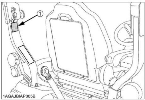
(1) ROPS identification plate (ROPS serial No.)

(1) Loader serial number
NOTE :
● The loader serial number label (1) is attached to the inside of the boom.
SPECIFICATIONS OF THE TRACTOR
SPECIFICATION TABLE
| Model BX25DLB-AU | |||
| PTO power *1 kW (HP) 13.2 (17.7) | |||
| Engine | Maker KUBOTA | ||
| Model D902 | |||
| Type Indirect injection, vertical, water-cooled, 4-cycle diesel | |||
| Number of cylinders 3 | |||
| Bore and stroke mm 72 x 73.6 | |||
| Total displacement cm 898 | |||
| Engine gross power *2 kW (HP) 17.1 (23.0) | |||
| Rated revolution rpm 3200 | |||
| Low idling revolution rpm 1350 to 1450 | |||
| Maximum torque N-m 56.1 | |||
| Battery 12V, RC: 80min, CCA: 540A | |||
| Fuel | Diesel fuel No.2 [above -10°C (14°F)] Diesel fuel No.1 [below -10°C (14°F)] | ||
| Capacities | Fuel tank L | 25 | |
| Engine crankcase (with filter) L | 3.1 | ||
| Engine coolant L | 2.7 | ||
| Recovery tank L | 0.4 | ||
| Transmission case L | 11.6 | ||
| Dimensions | Overall length (without 3P) mm | 2120 | |
| Overall length (with 3P) mm | 2425 | ||
| Overall width mm | 1145 | ||
| Overall height (with ROPS) mm | 2215 | ||
| 1255 (Top of seat) | |||
| Wheel base mm | 1400 | ||
| Min. ground clearance mm | 175 | ||
| Tread | Front mm | 930 | |
| Rear mm | 820 | ||
| Weight (with ROPS) kg | 720 | ||
| Clutch | N/A | ||
| Traveling system | Tire | Front | 18 x 8.50-10 (Turf, Bar, Ind.) |
| Rear | 26 x 12.00-12 (Turf, Bar, Ind.) | ||
| Steering | Hydrostatic type power steering | ||
| Transmission | Main: Hydrostatic transmission, High-Low gear shift (2 forward, 2 reverse) | ||
| Brake | Wet disk type | ||
| Min. turning radius m | 2.3 | ||
| Model | BX25DLB-AU | ||
| Hydraulic unit | Hydraulic control system Directional control, auto-return lever system | ||
| Pump capacity L/min. 23.5 | |||
| System pressure MPa (kgf/cm) *12.3 to 12.8 (126 to 130) | |||
| 3-point hitch SAE Category 1 | |||
| 3-point hitch Max. lift force *3 | At lift points N 5390 | ||
| 24 in. behind lift points N 3040 | |||
| Remote control valve coupler (rear : Option) | System 2 valves | ||
| Coupler ISO 7341 series A | |||
| Remote control valve coupler (front : Option) | System 2 valves | ||
| Coupler (nipple) ISO 7241-1 series B | |||
| PTO | Rear PTO | SAE 1-3/8, 6 splines | |
| Revolution 1 speed (540 rpm at 3142 engine rpm) | |||
| MID-PTO | USA No.5 (KUBOTA 10-tooth) involute spline | ||
| Revolution 1 speed (2500 rpm at 3043 engine rpm) | |||
The company reserve the right to change the specifications without notice.
NOTE: *1 Manufacturer's estimate
*2 SAE J1995
*3 See and check "IMPLEMENT LIMITATIONS."
TRAVELING SPEEDS
(At rated engine rpm)
| Model | BX25DLB-AU | ||
| Tire size (Rear) | 26 X 12.00 - 12 | ||
| Speed control pedal | Range gear shift lever | km / h | mph |
| Forward | Low | 0 to 6.5 | 0 to 4.0 |
| High | 0 to 13.5 | 0 to 8.4 | |
| Reverse | Low | 0 to 5.0 | 0 to 3.1 |
| High | 0 to 10.5 | 0 to 6.5 | |
The company reserves the right to change the specifications without notice.
SPECIFICATIONS OF THE LOADER
LOADER SPECIFICATIONS
| LOADER MODEL LA240A LA240A AU-SG | |||
| TRACTOR MODEL BX25DLB-AU | |||
| BOOM CYLINDER | BORE mm 40 | ||
| STROKE mm 326 | |||
| BUCKET CYLINDER | BORE mm 65 | ||
| STROKE mm 196 | |||
| CONTROL VALVE | 1 Detent Float Position, 2 Stage Bucket Dump, Power Beyond Circuit | ||
| RATED FLOW L/m 14 | |||
| MAXIMUM PRESSURE MPa (kg/cm) | 12.3 (125)2 | ||
| NET WEIGHT (APPROXIMATE) kg 170 175 | |||
BUCKET SPECIFICATIONS
| LOADER MODEL LA240A / LA240A AU-SG | ||
| MODEL | SQUARE 48" | |
| TYPE | RIGID | |
| WIDTH | mm | 1219 |
| DEPTH (L) | mm | 495 |
| HEIGHT (M) | mm | 465 |
| LENGTH (N) | mm | 538 |
| CAPACITY | STRUCK m3 | 0.14 |
| HEAPED m3 | 0.17 | |
| WEIGHT | kg | 60 |
NOTE :
● LA240A AU-SG means spill guard model.
DIMENSIONAL SPECIFICATIONS
| LOADER MODEL LA240A / LA240A AU-SG | |||
| TRACTOR MODEL BX25DLB-AU | |||
| A | MAX. LIFT HEIGHT (TO BUCKET PIVOT PIN) mm 1810 | ||
| B | MAX. LIFT HEIGHT UNDER LEVEL BUCKET mm 1680 | ||
| C | CLEARANCE WITH BUCKET DUMPED mm 1330 | ||
| D | REACH AT MAX. LIFT HEIGHT(DUMPING REACH) | mm 660 | |
| E | MAX. DUMP ANGLE deg. 45 | ||
| F | REACH WITH BUCKET ON GROUND mm 1390 | ||
| G | BUCKET ROLL-BACK ANGLE deg. 29 | ||
| H | DIGGING DEPTH mm 120 | ||
| J | OVERALL HEIGHT IN CARRYING POSITION | mm 990 | |

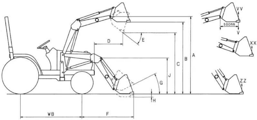
1AIABACAP003G
OPERATIONAL SPECIFICATIONS
| LOADER MODEL LA240A LA240A AU-SG | ||||
| TRACTOR MODEL BX25DLB-AU | ||||
| V R | ATED OPERATING LOAD (500 mm FORWARD, MAX. HEIGHT) kg | 220 | ||
| VV | BUCKET ROLL-BACK FORCE AT MAX. HEIGHT N 4750 | |||
| XX | BUCKET ROLL-BACK FORCE AT 1500mm HEIGHT N 5600 | |||
| ZZ | BUCKET ROLL-BACK FORCE AT GROUND LEVEL N 5490 | |||
| RAISING TIME sec. 3.2 3.2 | ||||
| LOWERING TIME | sec. | 2.7 2.5 | ||
| BUCKET DUMPING TIME | sec. | 1.4 2.0 | ||
| BUCKET ROLLBACK TIME | sec. | 2.3 2.3 | ||

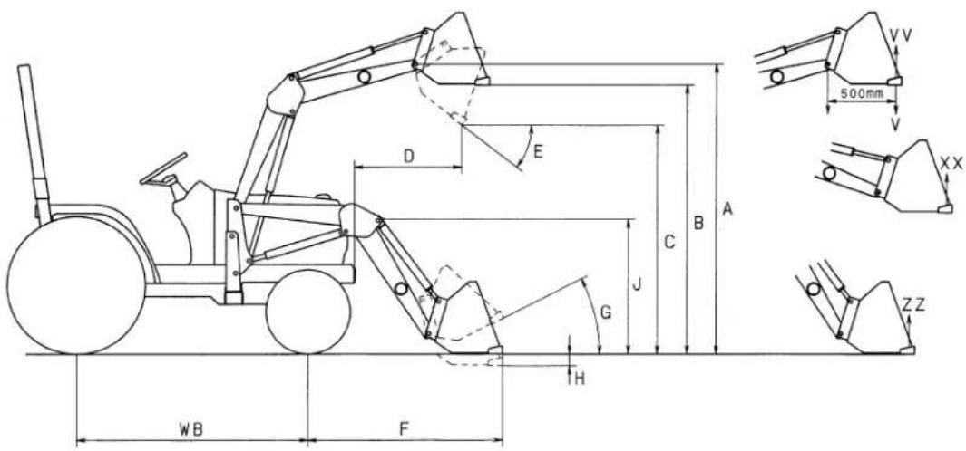
1AIABACAP003G
LOADER TERMINOLOGY

(1) Loader control lever
(2) Side frame
(3) Mounting pin
(4) Main frame
(5) Boom cylinder
(6) Boom
(7) Bucket cylinder
(8) Bucket
(9) Lock lever
(10) Spill guard valve (Spill guard model only)
SPECIFICATIONS OF THE BACKHOE
BACKHOE SPECIFICATIONS
■Dimensions
| Model BT602 | ||
| Transport height (A) 1719 mm | ||
| Stabilizer spread-transport (B) 1296 mm | ||
| Ground clearance (C) 240 mm | ||
| Overall width (E) 1128 mm | ||
| Maximum digging depth (F) 1889 mm | ||
| Digging depth, 2 ft. flat bottom (G) 1842 mm | ||
| Digging depth, 8 ft. flat bottom (H) 1059 mm | ||
| Operating height, fully raised (J) | 2539 m | |
| Loading height | (K) 1533 mm | |
| Loading reach | (L) 1016 mm | |
| Reach from swing pivot | (M) | 2612 mm |
| Swing pivot to rear axle center line | (N) 726 mm | |
| Bucket rotation | (P) | 180 deg. |
| Stabilizer spread-operating | (R) 1862 mm | |
| Angle of departure per SAE J1234 | (A3) | 20.1 deg. |
| Leveling angle | (U) | 11 deg. |
| Swing arc | 140 deg. | |
NOTE :
● The specifications are taken with KUBOTA BX25DLB tractor. (Tire size : Front 18 X 8.5-10, Rear 26 X 12.00-12)

Specifications
Digging force (Per SAE J49)
| With bucket cylinder 8610 N | |
| With dipperstick cylinder 5209 N |
Cycle Time (seconds)
| Boom cylinder, extend 4.5 | |
| Boom cylinder, retract 3.7 | |
| Swing cylinder, from 90 degrees to center 1.5 | |
| Dipperstick cylinder, extend 4.1 | |
| Dipperstick cylinder, retract 3.4 | |
| Bucket cylinder, extend 3.1 | |
| Bucket cylinder, retract 2.4 | |
| Stabilizer cylinder, max. height to ground 2.9 | |
| Stabilizer cylinder, ground to max. height 2.3 |
Hydraulic cylinders
| Boom cm | Dipperstick cm | Bucket cm | Stabilizer cm | Swing cm | |
| Rod diameter 3.0 2.5 | 2.5 | 2.5 | 3.0 | ||
| Cylinder bore 6.5 6.0 | 5.0 | 6.0 | 6.0 |
Bucket Sizes
| Width cm | SAE truck Capacity m3 | SAE Heaped Capacity m3 | Number of Teeth | Weight kg | |
| Trenching 8" 20.3 0 | .009 0.011 2 10 | ||||
| Trenching 12" 30.5 | 0.014 0.020 3 13 |
■Lift Capacity (Per SAE J31)
Lift capacities shown are 87% of maximum lift force, according to SAE definition.

line
| RATED LIFT CAPACITY (OVER END)-kg | m | |---|---| | 0.6 | 0.5 | | 1.2 | 1.9 | | 1.8 | 1.2 | | 2.4 | 0.0 | | 2.6 | 1.8 | | 2.12 | 1.7 | | 2.09 | 1.8 | | 2.03 | 1.2 | | 2.01 | 1.2 | | 2.14 | 1.1 | | 262 | 1.1 |1HNAAACAP002D
BACKHOE TERMINOLOGY

(1) Backhoe bucket
(2) Bucket teeth
(3) Bucket link
(4) Bucket cylinder
(5) Dipperstick
(6) Dipperstick cylinder
(7) Boom
(8) Boom cylinder
(9) Swing frame
(10) Main frame
(11) Swing cylinder
(12) Stabilizer
(13) Stabilizer pad
(14) Stabilizer cylinder
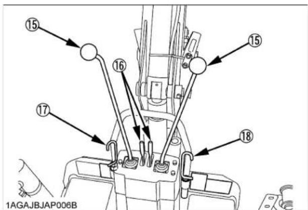
(15) Joystick control
(16) Stabilizer control
(17) Swing lock pin
(18) Boom lock pin
IMPLEMENT LIMITATIONS
The KUBOTA Tractor has been thoroughly tested for proper performance with implements sold or approved by KUBOTA. Use with implements which are not sold or approved by KUBOTA and which exceed the maximum specifications listed below, or which are otherwise unfit for use with the KUBOTA Tractor may result in malfunctions or failures of the tractor, damage to other property and injury to the operator or others. [Any malfunctions or failures of the tractor resulting from use with improper implements are not covered by the warranty.]
| Tread (max. width) Lower link end max. | lifting weight W0 | ||
| Front Rear | |||
| BX25DLB-AU 910 | mm 820 mm 550 kg | ||
| Actual figures | |||
| Implement weight W1 and / or size | Max. HitchLoad W2 | Trailer loading weight W3 Max. capacity | |
| BX25DLB-AU | As in the following list(Shown on the next page) | 250 kg 800 kg | |
Lower link end max. lifting weight.....The max. allowable load which can be put on the lower link end : W0 Implement weight.....The implement's weight which can be put on the lower link : W1 Max. hitch load..... W2 Trailer loading weight.....The max. loading weight for trailer (without trailer's weight) : W3

1HNAAAAAP0260

natural_image
Simple line drawing of a mechanical system with rollers and a lever, no text or symbols presentW1

NOTE :
- Implement size may vary depending on soil operating conditions.
- Strictly follow the instructions outlined in the operator's manual of the mounted or trailed machinery or trailer, and do not operate the combination tractor - machine or tractor - trailer unless all instructions have been followed.
● Forestry Application
Following hazards exist;
(a) toppling trees, primarily in case a rear-mounted tree grab-crane is mounted at the rear of the tractor;
(b) penetrating objects in the operator's enclosure, primarily in case a winch is mounted at the rear of the tractor.
Optional equipments such as OPS (Operator Protective Structure), FOPS (Falling Object Protective Structure), etc. to deal with these hazards and other related hazards are not available for this tractor. Without such optional equipment use is limited to tractor specific applications like transport and stationary work.
| Implement Remarks | BX25DLB-AU | ||
| Backhoe *1 | Max. Digging Depth mm | 1840 | |
| Max. Weight kg | 262 w/o Bucket | ||
| Front-end loader *2 | Max. lifting capacity kg (Bucket pivot pin, max. height) *3 | 340 | |
| Max. width cm | 122 | ||
| Sub frame Necessary | |||
| Mower | Mid-mount | Max. cutting width cm | 152 |
| Max. weight kg | 115 | ||
| Rotary-Cutter (1 Blade) | Max. cutting width cm | 107 | |
| Max. weight kg | 140 | ||
| Rear-mount (2 or 3 Blade) | Max. cutting width cm | 152 | |
| Max. weight kg | 140 | ||
| Flail-mower Max. | cutting width cm | 107 | |
| Sickle bar Max. | cutting width cm | 122 | |
| Rotary tiller | Max. tilling width cm | 107 | |
| Max. weight kg | 170 | ||
| Bottom plow Max. size | in. | 14 x 1 | |
| Disc plow | Max. size in. | 22 x 1 | |
| Cultivator | Max. size cm | 1221 Row | |
| Disc harrow | Max. harrowing width cm | 137 | |
| Max. weight kg | 140 | ||
| Sprayer | Max. tank capacity L | 150 | |
| Front blade | Max. cutting width cm | 152 | |
| Sub frame Necessary | |||
| Rear blade | Max. cutting width cm | 152 | |
| Max. weight kg | 160 | ||
| Box blade | Max. cutting width cm | 122 | |
| Max. weight kg | 170 | ||
| Snow blower (Front) | Max. working width cm | 127 | |
| Max. weight kg | 160 | ||
| Sub frame Necessary | |||
| Post hole digger | Digging depth cm | 114 | |
| Rotary broom | Cleaning width cm | 119 | |
| Trailer | Max. load capacity kg | 800 *4 | |
| Max. weight kg | 1100 | ||
*1 KUBOTA provides BT602 Backhoe for BX25DLB-AU.
No other Backhoe installed by 3-point hitch is permitted for BX25DLB-AU.
*2 KUBOTA provides LA240A, LA240A AU-SG Front-end Loader for BX25DLB-AU.
*3 The value contains the weight of KUBOTA standard bucket.
*4 Reduce speed and trailer loads when operating in slippery conditions or when operating on slopes and utilize front wheel drive.
NOTE :
- Implement size may vary depending on soil operating conditions.
INSTRUMENT PANEL AND CONTROLS
■Instrument Panel, Switches and Hand Controls

ILLUSTRATED CONTENTS
(1) Easy Checker(TM).... 24,37
(2) Tachometer.... 38
(3) Hazard light switch.... 32
(4) Turn signal light switch.... 32
(5) Head light switch.... 32
(6) Fuel gauge.... 37
(7) Coolant temperature gauge.... 37
(8) Hourmeter.... 38
(9) Key switch.... 24
■Foot and Hand Controls

ILLUSTRATED CONTENTS
(1) Brake pedal.... 24,32,34,38
(2) Parking brake lock pedal.... 24,32,34,38
(3) 3-Point hitch lowering speed knob.... 49
(4) Cutting height control dial.... 52
(5) PTO select lever.... 43
(6) PTO clutch lever.... 24,44
(7) Differential lock pedal.... 39
(8) Speed set rod 35
(9) Hand throttle lever.... 24,34
(10) Loader control lever.... 58,59
(11) Lock lever.... 24,62
(12) Speed control pedal 24,35
(13) Hydraulic control lever.... 24,49,52
(14) Front wheel drive lever.... 34
(15) Range gear shift lever (Hi-Lo).... 24,33
(16) Operator's seat.... 31
(17) Seat belt.... 32
PRE-OPERATION CHECK OF THE TRACTOR
DAILY CHECK
To prevent trouble from occurring, it is important to know the condition of the tractor well. Check it before starting.

CAUTION
To avoid personal injury:
- Be sure to check and service the tractor on a level surface with the engine shut off and the parking brake "ON" and implement lowered to the ground.
Check item
- Walk around inspection
- Check engine oil level
- Check transmission oil level
- Check coolant level
- Clean grill and radiator screen
- Check air cleaner evacuator valve (When used in a dusty place)
- Check brake pedal
- Check indicators, gauges and meter
- Check lights
- Check wire harness
- Check seat belt and ROPS
- Check movable parts
- Refuel
(See "DAILY CHECK" in "PERIODIC SERVICE OF THE TRACTOR" section.)
- Care of danger, warning and caution labels (See "DANGER, WARNING AND CAUTION LABELS" in "SAFE OPERATION" section.)
PRE-OPERATION CHECK OF THE LOADER
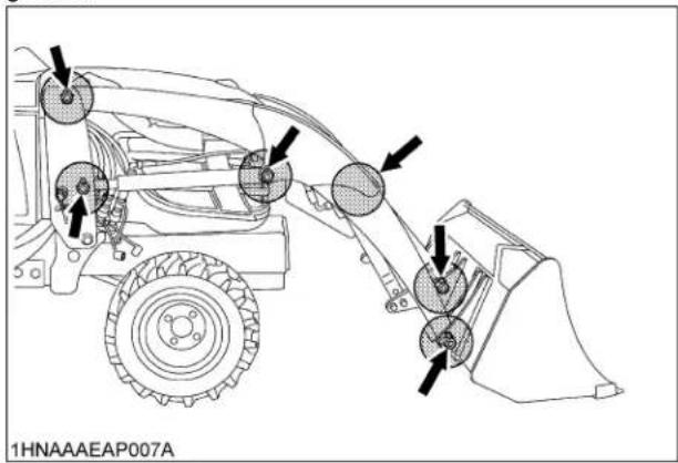
LUBRICATION
Lubricate all grease fittings with SAE multipurpose grease.
TRANSMISSION FLUID
Check tractor transmission fluid level. Add fluid if necessary. Refer to the tractor's Operator's Manual for instructions and proper fluid. Repeat this check after purging air from the system. At that time, it will be necessary to add transmission fluid.
IMPORTANT :
● To check tractor transmission fluid level, lower the bucket to the ground and lower the 3 point hitch.
REAR BALLAST
[Standard model]

CAUTION
To avoid personal injury:
- For tractor stability and operator's safety, rear ballast should be added to the rear of the tractor in the form of 3-point counter weight and rear wheel ballast. The amount of rear ballast will depend on the application.
| Implement as Counter Weight | |
| Box Blade | Approx. 190 kg |
| Rear Blade | |
| Rotary Tiller | |
| Ballast Box | |
◆Liquid ballast in rear tires
Water and calcium chloride solution provides a safe and economical ballast. Used properly, it will not damage tires, tubes or rims. The addition of calcium chloride is recommended to prevent the water from freezing. Use of this method of weighting the wheels has full approval of the tire manufacturers. See your tire dealer for this service.
Liquid weight per tire (75 Percent filled)
| Tire sizes 26 x 12-12 | |
| Slush free at -10 °CSolid at -30 °C[Approx. 1 kg CaCl2 per 4 L of water] | 45 kg |
| Slush free at -24 °CSolid at -47 °C[Approx. 1.5 kg CaCl2 per 4 L of water] | 50 kg |
| Slush free at -47 °CSolid at -52 °C[Approx. 2.25 kg CaCl2 per 4 L of water] | 56 kg |
IMPORTANT :
- Do not fill tires with water or solution more than 75% of full capacity (to the valve stem level at 12 o'clock position).

(1) Air
(A) Correct: 75% Full
Air compresses like a cushion
(2) Water
(B) Incorrect: 100% Full
Water can not be compressed
NOTE :
- When mounting a heavy rear implement, liquid in the tires may not be required.
IMPORTANT :
- Do not add liquid ballast or any other weights to the front tires.
[Spill guard model]
![KUBOTA LA240A - [Spill guard model] - 1](/content/2026/05/991150/images/78957c80ddad3f7aaff7a7e9530db2215c373c684c32825deafd01cdf5b68bc5.jpg)
WARNING
To avoid personal injury or death:
- Do not exceed ROL (Rated operation load).
- Do not operate the loader without counter weight.
- Do not exceed 10 km/h when travelling with load.
- ROL is calculated with standard bucket. Optional attachments (4IN1 bucket etc.) will reduce ROL.
[With counter weight]
| Rated operation load (ROL) | 190 kg |
| Counter weight required *1 | 70 kg |
[With backhoe]
| Rated operation load (ROL) | 220 kg |
*Be sure to install the counter weight approved by KUBOTA.
The use of a counter weight significantly reduces the front axle and tire load during loader operation. It also increases the fore/aft stability of the tractor/loader by shifting weight from the front axle to the rear axle. Failure to use the recommended counter weight can result in damage to the tractor, reduced braking capability, and instability of the tractor/loader.

natural_image
Isometric line drawing of an electrical enclosure with three switches and a labeled component (no text or symbols on the diagram itself)(1) Counter weight
IMPORTANT :
● Water ballasting the rear tires of the tractor does not reduce the front axle load.
RATED OPERATING LOAD (SPILL GUARD MODEL ONLY)

WARNING
To avoid personal injury or death:
- Do not exceed ROL (Rated operation load).
- Do not operate the loader without counter weight.
- Do not exceed 10 km/h when travelling with load.
-
Use only tires approved by Kubota for loader use.
-
ROL is calculated with standard bucket. Optional attachments (4IN1 bucket etc.) will reduce ROL.
- ROL is determined with the tractor static, on a hard level surface. Reduce load from the listed ROL if operating on uneven or sloping terrain.
- Remove the mid mount mower deck (if fitted) before operating the loader.
[With counter weight]
| Rated operation load (ROL) | 190 kg |
| Counter weight required *1 | 70 kg |
[With backhoe]
| Rated operation load (ROL) | 220 kg |
*Be sure to install the counter weight approved by KUBOTA.
| Attachment | Width (mm) | Capacity (m3) Attachment | Rated Operating Load (kg) | |||
| Heaped Struck With Backhoe with counter Weight | ||||||
| LA240A AU-SG STD Bucket | 1219 0.1 | 7 0.14 60 | 220 | 190 | ||
| Material | DENSITY (kg/m3) | Standard Bucket | ||||
| LA240A AU-SG with Backhoe | LA240A AU-SG with counter weight | |||||
| Heaped Weight (kg) | Struck Weight (kg) | Heaped Weight (kg) | Struck Weight (kg) | |||
| Blue Metal | 1700 | 289 X | 238 X | 289 X | 238 X | |
| Clay Dry | 1100 | 187 O | 154 O | 187 O | 154 O | |
| Clay Wet | 1600 | 272 X | 224 X | 272 X | 224 X | |
| Earth Dry | 1070 | 182 O | 150 O | 182 O | 150 O | |
| Earth Moist | 1630 | 277 X | 228 X | 277 X | 228 X | |
| Earth Wet | 1250 | 213 O | 175 O | 213 X | 175 O | |
| Fertilizer | 1089 | 185 O | 152 O | 185 O | 152 O | |
| Gypsum | 2547 | 433 X | 357 X | 433 X | 357 X | |
| Lime | 849 | 144 O | 119 O | 144 O | 119 O | |
| Sand Dry | 1720 | 292 X | 241 X | 292 X | 241 X | |
| Sand Wet | 1900 | 323 X | 266 X | 323 X | 266 X | |
| Water | 1000 | 170 O | 140 O | 170 O | 140 O | |
| Wheat | 769 | 131 O | 108 O | 131 O | 108 O | |
TIRE INFLATION
Insure that the tractor tires are properly inflated. See "TIRES, WHEELS AND BALLAST" section.
TEST OPERATION

WARNING
To avoid serious personal injury:
- Keep engine speed at low idle during the test operation.
- Escaping hydraulic fluid under pressure can have sufficient force to penetrate skin, causing serious personal injury.
Before disconnecting lines, be sure to relieve all pressure by moving the controls.
Before applying pressure to the system, be sure all connections are tight and that lines, tubes and hoses are not damaged.
Fluid escaping from a very small hole can be almost invisible. Use a piece of cardboard or wood, rather than your hands to search for suspected leaks.
If injured by escaping fluid, see a doctor at once. Serious infection or allergic reaction will develop if proper medical treatment is not administered immediately.

flowchart
graph TD
    A["Surface"] --> B["Pointing"]
    B --> C["Rotation"]
    C --> D["Pointing"]
    D --> E["Rotation"]
    E --> F["Pointing"]
    F --> G["Pointing"]
    G --> H["Pointing"]
    H --> I["Pointing"]
    I --> J["Pointing"]
    J --> K["Pointing"]
    K --> L["Pointing"]
    L --> M["Pointing"]
    M --> N["Pointing"]
    N --> O["Pointing"]
    O --> P["Pointing"]
    P --> Q["Pointing"]
    Q --> R["Pointing"]
    R --> S["Pointing"]
    S --> T["Pointing"]
    T --> U["Pointing"]
    U --> V["Pointing"]
    V --> W["Pointing"]
    W --> X["Pointing"]
    X --> Y["Pointing"]
    Y --> Z["Pointing"]
1AIABACAP011B
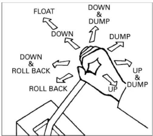
- When the lever is at each corner position marked by asterisk (*), boom and bucket cylinders work at the same time. However, the blank position (Raise & Roll back) is not recommended for scooping because of insufficient lift force.
To begin test operation, slightly move the control lever from "N" position. Slowly raise the loader boom just enough for the bucket to clear the ground when fully dumped. Slowly work through the dump and roll back cycles.
IMPORTANT :
- If the boom or bucket does not work in the directions indicated on the label, lower the bucket to the ground, stop the engine, and relieve all hydraulic pressure. Recheck and correct all hydraulic connections.
This control valve has 2 stage dump positions. The first "Regenerative" dump position, activated by moving the lever to the right, features high speed for efficient normal loader operations.
The second "Regular" dump position, activated by moving the lever further to the right, features increased power. This second position should be used when operating implements other than the loader with this control valve. These 2 positions are separated by a "Feel" position for your convenience.
REMOVING AIR FROM HYDRAULIC SYSTEM
Repeat raising and lowering the boom and bucket operations until all the air is removed from the system and the system responds properly.
IMPORTANT :
- Do not move the control lever into float position when the bucket is off the ground.
PRE-OPERATION CHECK OF THE BACKHOE
Prior to starting the engine, make pre-operation checks according to "MAINTENANCE OF THE BACKHOE" section.

CAUTION
To avoid personal injury:
- Read "SAFE OPERATION" section in the front of this manual.
- Read the warning and caution labels located on the backhoe.
● Make sure the swing lock pin is set before entering or exiting the backhoe operator area.
PRE-OPERATING INSTRUCTION
OPERATOR'S SEAT
Operator's seat for the BX25DLB-AU tractor can be used to operate loader and backhoe. See "OPERATING THE TRACTOR" section for the detail to turn the seat around for backhoe operation. When operating backhoe, the seat belt should be used.

(1) Operator's seat (backhoe position)
Seat Belt

CAUTION
To avoid personal injury:
● Always use the seat belt when the ROPS is installed.
Do not use the seat belt if a foldable ROPS is down or there is no ROPS.
Adjust the seat belt for proper fit and connect to the buckle. The seat belt is auto-locking retractable type.
BALLAST

WARNING
To avoid serious personal injury or death:
● Never remove loader to ensure tractor stability at all times.
IMPORTANT :
- Do not add liquid ballast or any other weights to the front tires.
● While BT602 backhoe is installed on the tractor, liquid ballast in the rear tires should be removed.
TIRE INFLATION
Insure that the tractor tires are properly inflated. See "TIRES, WHEELS AND BALLAST" section.
To avoid personal injury:
- Read "SAFE OPERATION" in the front of this manual.
- Read the danger, warning and caution labels located on the tractor.
● To avoid the danger of exhaust fume poisoning, do not operate the engine in a closed building without proper ventilation.
● Never start engine while standing on ground. Start engine only from operator's seat.
● Make it a rule to set all shift levers to "NEUTRAL" positions and to place PTO lever in "OFF" position before starting the engine.
IMPORTANT :
- Do not use starting fluid or ether.
● To protect the battery and the starter, make sure that the starter is not continuously turned for more than 30 seconds.
STARTING THE ENGINE
1. Make sure the parking brake is set.
- To set the parking brake;
(1) Depress the brake pedal.
(2) Latch the brake pedal on pushing and holding the parking brake lock pedal then releasing pressure on the brake pedal.
- To release the parking brake, depress the brake pedal again.

(1) Brake pedal
(A) "DEPRESS"
(2) Parking brake lock pedal
(B) "PUSH DOWN (2)
WHILE DEPRESSING (1)"
NOTE :
- It is recommended that the operator practice engaging and disengaging the parking brake on a flat surface without the engine running before operating the tractor for the first time.
2. Place the PTO clutch lever in "OFF" position.
3. Place the speed set rod in "OFF" position.
Place the speed control pedal in "NEUTRAL" position.
Place the range gear shift lever (Hi-Lo) in "NEUTRAL" position.
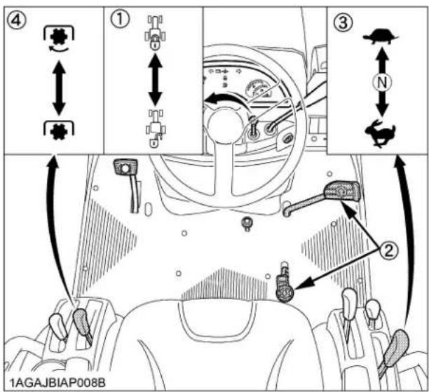
(1) Speed set rod "ON"


"OFF"
(2) Speed control pedal
(3) Range gear shift lever (Hi-Lo)
(4) PTO clutch lever "ON"

(N) "NEUTRAL"



NOTE :
● The speed control pedal automatically return to "NEUTRAL" when the operator's foot is released from the pedal.
- Lock the loader control lever in "NEUTRAL" position.

(1) Loader control lever
(A) "LOCK"
(2) Lock lever
- Move the hydraulic control lever forward. (With the implement in place.)
To lower implement, move the hydraulic control lever forward.
Check that implement is down at lowest position.
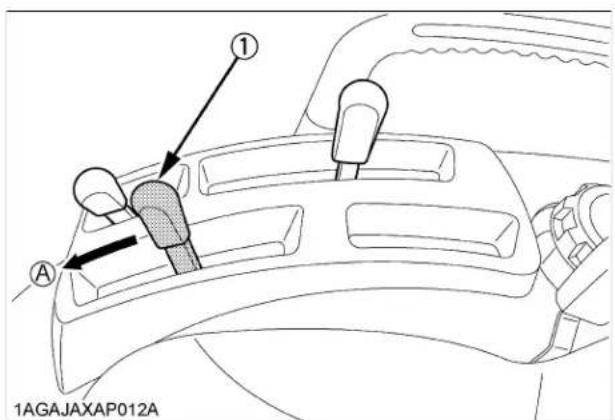
(1) Hydraulic control lever (A) "DOWN"
- Set the throttle lever to about 1/2 way.

(1) Hand throttle lever "INCREASE" "DECREASE"
- Insert the key into the key switch and turn it "ON".

"OFF"
"ON"
"PREHEAT"
"START"
◆Check Easy Checker(TM) Lamps:
- When the key is turned "ON", lamps (2) (3) (4) (5) (6) only should come on. If trouble should occur at any location while the engine is running, the warning lamp corresponding to that location comes on.

(1) Turn signal/Hazard light indicator
(2) Preheat
(3) Electrical charge
(4) Engine oil pressure
(5) Coolant temperature indicator
(6) Low fuel indicator
(7) Key switch
IMPORTANT :
- Daily checks with the Easy Checker(TM) only, are not sufficient. Never fail to conduct daily checks carefully by referring to Daily Check section. (See "DAILY CHECK" in "PERIODIC SERVICE OF THE TRACTOR" section.)
8. Turn the key to "PREHEAT" position and hold it for about 2 to 3 seconds.
For the appropriate preheating time, refer to the table below:
| Temperature Preheating Time | |
| Over 0°2 to 3 sec. | |
| -5 to 0°6 sec. | |
| -15 to -5°10 sec. | |
NOTE :
● Glow plug indicator (2) comes on while engine is being preheated.
9. Turn the key to "START" position and release it when the engine starts.
IMPORTANT :
- Because of safety devices, the engine will not start except when the speed control pedal is in "NEUTRAL" position and the PTO clutch lever is in "OFF" position respectively.
■Cold Weather Starting
When the ambient temperature is below -5ircC and the engine is very cold. If the engine fails to start after 10 seconds, turn off the key for 30 seconds. Then repeat steps 8 and 9. To protect the battery and the starter, make sure that the starter is not continuously turned for more than 30 seconds.
■Block Heater (Option)
A block heater is available as an option from your dealer. It will assist you in starting your tractor when the ambient temperature is below -15°C
10. Check to see that all the lamps on the Easy Checker(TM) are "OFF".
If the lamp is still "ON", immediately stop the engine and determine the cause.
STOPPING THE ENGINE
- After slowing the engine to idle, turn the key to "OFF".
- Remove the key.
NOTE :
- If key does not stop the engine, consult your local KUBOTA Dealer.
WARMING UP

CAUTION
To avoid personal injury:
- Be sure to set the parking brake during warm-up.
- Be sure to set all shift levers to "NEUTRAL" positions and to place PTO lever in "OFF" position during warm-up.
For 5 minutes after engine start-up, allow engine to warm up without applying any load, this is to allow oil to reach every engine part. If load should be applied to the engine without this warm-up period, trouble such as seizure, breakage or premature wear may develop.
■Warm-up and Transmission Oil in the Low Temperature Range
Hydraulic oil serves as transmission fluid. In cold weather, the oil may be cold with increased viscosity. This can cause delayed oil circulation or abnormally low hydraulic pressure for some time after engine start-up. This in turn can result in premature wear in the hydraulic system or malfunctions such as resistance in the speed control pedal and difficulty engaging the range gear shift lever. To prevent the above, observe the following instructions: Warm up the engine at about 50% of rated rpm according to the table below:
| Ambient temperature Warm-up time requirement | |
| Above 0°At least 5 minutes | |
| -10 to 0°To 10 minutes | |
| -20 to -10°To 15 minutes | |
| Below -20°More than 15 minutes | |
IMPORTANT :
- Do not operate the tractor under full load condition until it is sufficiently warmed up.
JUMP STARTING

CAUTION
To avoid personal injury:
● Battery gases can explode. Keep cigarettes, sparks, and flames away from battery.
- If tractor battery is frozen, do not jump start engine.
- Do not connect other end of negative (-) jumper cable to negative (-) terminal of tractor battery.
- When carrying on the following steps 4 and 11, do not allow the positive (+) terminal of the battery to touch other parts.
When jump starting engine, follow the instructions below to safely start the engine.
-
Bring helper vehicle with a battery of the same voltage as disabled tractor within easy cable reach. "THE VEHICLES MUST NOT TOUCH".
-
Engage the parking brakes of both vehicles and put the shift levers in "NEUTRAL". Shut both engines off.
-
Put on safety goggles and rubber gloves.
-
Take the dead battery out and put it on the step.
-
Ensure the vent caps are securely in place. (if equipped)
-
Attach the red clamp to the positive (red, (+) or pos.) terminal of the dead battery and clamp the other end of the same cable to the positive (red, (+) or pos.) terminal of the helper battery.
-
Clamp the other cable to the negative (black, (-) or neg.) terminal of the helper battery.
-
Clamp the other end to the engine block or frame of the disabled tractor as far from the dead battery as possible.
-
Start the helper vehicle and let its engine run for a few moments. Start the disabled tractor.
-
Disconnect the jumper cables in the exact reverse order of attachment. (Steps 8, 7 and 6).
-
Put the battery back and fix it.

(1) Dead battery
(2) Jumper cables
(3) Engine block or frame
(4) Helper battery
IMPORTANT :
● This machine has a 12volt negative (-) ground starting system.
- Use only same voltage for jump starting.
- Use of a higher voltage source on tractors electrical system could result in severe damage to tractors electrical system.
Use only matching voltage source when "Jump starting" a low or dead battery condition.
How a new tractor is handled and maintained determines the life of the tractor.
A new tractor just off the factory production line has been, of course, tested, but the various parts are not broken in, so care should be taken to operate the tractor for the first 50 hours at a slower speed and avoid excessive work or operation until the various parts become "broken-in." The manner in which the tractor is handled during the "breaking-in" period greatly affects the life of your tractor. Therefore, to obtain the maximum performance and the longest life of the tractor, it is very important to properly break-in your tractor. In handling a new tractor, the following precautions should be observed.
■Do not Operate the Tractor at Full Speed for the First 50 Hours.
- Do not start quickly nor apply the brakes suddenly.
- In winter, operate the tractor after fully warming up the engine.
- Do not run the engine at speeds faster than necessary.
- On rough roads, slow down to suitable speeds. Do not operate the tractor at fast speed.
The above precautions are not limited only to new tractors, but to all tractors. But it should be especially observed in the case of new tractors.
■Changing Lubricating Oil for New Tractors
The lubricating oil is especially important in the case of a new tractor. The various parts are not "broken-in" and are not accustomed to each other; small metal grit may develop during the operation of the tractor; and this may wear out or damage the parts. Therefore, care should be taken to change the lubricating oil a little earlier than would ordinarily be required.
For further details of change interval hours, See "MAINTENANCE OF THE TRACTOR" section.
BOARDING AND LEAVING THE TRACTOR
- Never try to get on or off a moving tractor or jump off the tractor to exit.
- Face the tractor when getting into or out of the tractor. Do not use the controls as hand holds to prevent inadvertent machine movements.
- Always keep steps and floor clean to avoid slippery conditions.
OPERATING FOLDABLE ROPS

CAUTION
To avoid personal injury:
- When raising or folding the ROPS, apply parking brake, stop the engine and remove the key.
Always perform function from a stable position at the rear of tractor. - Fold the ROPS down only when absolutely necessary and fold it up and lock it again as soon as possible.
● Before proceeding to fold ROPS, check for any possible interference with installed implements and attachments.
If interference occurs, contact your KUBOTA Dealer.
■To Fold the ROPS
- Loosen the holding knob bolts.

(1) Holding Knob bolts
- Remove both set pins.
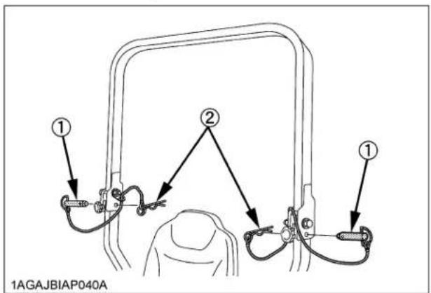
(1) Set pins
(2) Hair pins
- Fold the ROPS.

CAUTION
To avoid personal injury:
● Hold the ROPS tightly with both hands and fold the ROPS slowly and carefully.
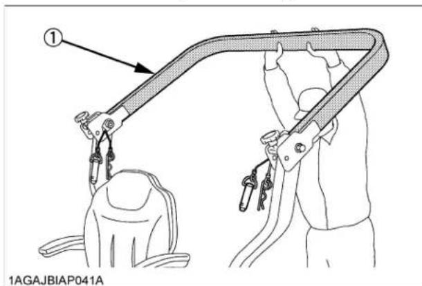
(1) ROPS
- Align set pin holes and insert both set pins and secure them with the hair pins.

CAUTION
To avoid personal injury:
● Make sure that both set pins are properly installed and secured with the hair pins.

(1) Set pins
(2) Hair pins
NOTE :
● Take care not to bump the ROPS against the rod of backhoe cylinder when folding the ROPS.
■To Raise the ROPS to Upright Position
- Remove both hair pins and set pins.
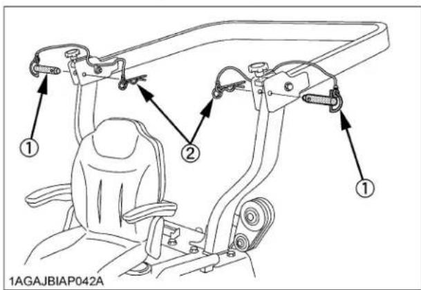
(1) Set pins
(2) Hair pins
- Raise ROPS to the upright position.

CAUTION
To avoid personal injury:
● Hold the ROPS tightly with both hands and raise the ROPS slowly and carefully.
- Align set pin holes, insert both set pins. Secure them with the hair pins.

CAUTION
To avoid personal injury:
● Make sure that both set pins are properly installed as soon as the ROPS is in the upright position and secured with the hair pins.

(1) Set pins
(2) Hair pins
- Tighten the holding knob bolts.
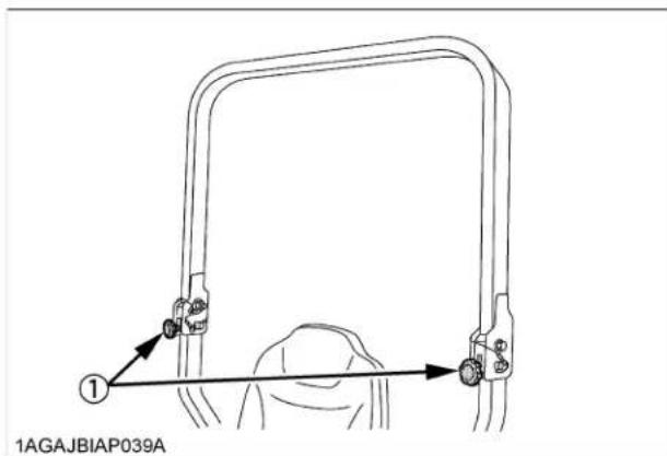
(1) Holding knob bolts
■Adjustment of Foldable ROPS
- Adjust free fall of the ROPS upper frame regularly.
- If you feel less friction in folding the ROPS, tighten the nut (1) until you feel the right friction in the movement.
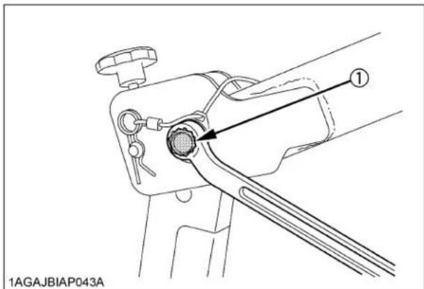
(1) Nut
STARTING
1. Adjust the operator's position and engage the seat belt.
NOTE :
● The seat and suspension should be adjusted to ensure that the controls are comfortably at hand for the operator, ensuring that the operator maintains a good posture.

(A) "TRACTOR DRIVING POSITION"
(B) "BACKHOE POSITION"
Operator's Seat

CAUTION
To avoid personal injury:
● Make adjustments to the seat only while the tractor is stopped.
● Make sure that the seat is completely secured after each adjustment.
- Do not allow any person other than the operator to ride on the tractor.
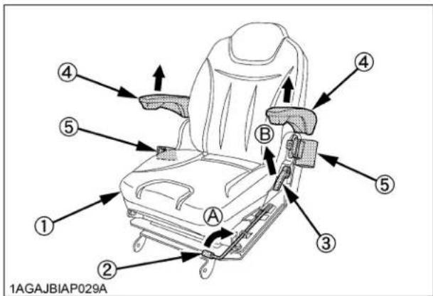
(1) Seat
(A) "PULL UP"
(2) Position adjust lever
(B) "PULL"
(3) Backrest tilt adjust lever
(4) Arm rest
(5) Seat belt
◆Travel adjustment
Pull up the position adjust lever and slide the seat backward or forward, as required. The seat will lock in position when the lever is released.
◆Tilt adjustment
Pull the backrest tilt adjust lever and tilt the backrest to the desired position.
IMPORTANT :
● After adjusting the operator's seat, be sure to check that the seat is properly locked.
- Be sure the operator's seat is out of contact with the top link.
- See "REVERSING THE SEAT" section when using seat in backhoe position.
Seat Belt

CAUTION
To avoid personal injury:
● Always use the seat belt when the ROPS is installed.
Do not use the seat belt if a foldable ROPS is down or there is no ROPS.
Adjust the seat belt for proper fit and connect to the buckle. The seat belt is auto-locking retractable type.
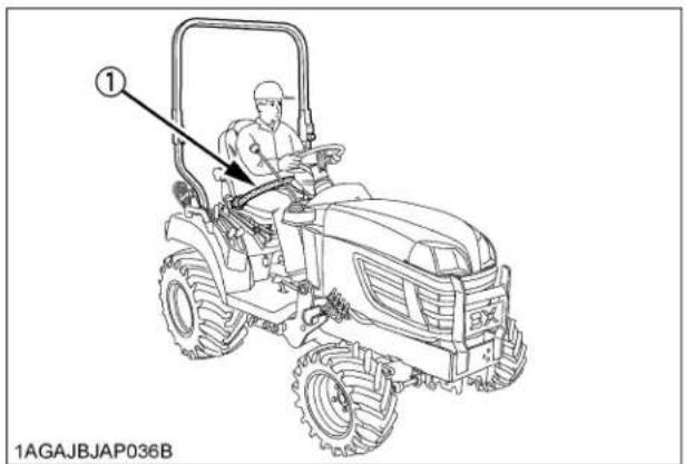
(1) Seat belt
2. Selecting Light Switch Positions.
■Head Light Switch
(A) ..... Head lights "ON".
(B) ..... Head lights "OFF".
Hazard Light Switch
When hazard light switch is turned counter-clockwise, the hazard lights flash along with the indicator on the instrument panel. Turn the switch clockwise to turn off the light.
(A) ..... Hazard lights "ON".
(B) ..... Hazard lights "OFF".
■Turn Signal Light Switch
To indicate a right turn, turn the switch clockwise.
To indicate a left turn, turn the switch counter-clockwise.
When the left or right turn signal is activated in combination with the hazard lights, the indicated turning light will flash and the other will stay on.
NOTE :
- Be sure to return switch to center position after turning.

(1) Hazard light switch
(2) Head light switch
(3) Turn signal light switch
(A) "ON"
(B) "OFF"
(C) "RIGHT TURN"
(D) "LEFT TURN"
3. Checking the Brake Pedal.
Brake Pedal
Make sure to latch the brake pedal with the parking brake lock pedal. Use both right and left feet for the procedure.

CAUTION
To avoid personal injury:
● An accident may occur if the tractor is suddenly braked, such as by heavy towed loads shifting forward or loss of control.
● The braking characteristics are different between 2 and 4-wheel drive. Be aware of the difference and use carefully.
- When driving on icy, wet or loose surfaces, make sure the tractor is correctly ballasted to avoid skidding and loss of steering control. Operate at reduced speed.

(1) Brake pedal
(A) "DEPRESS"
(2) Parking brake lock pedal
(B) "PUSH DOWN (2)
WHILE DEPRESSING (1)"
4. Start the engine.
5. Raise the Implement. (see "HYDRAULIC UNIT" section.)
Move the hydraulic control lever rearward.

(1) Hydraulic control lever "RAISED"
(N) "NEUTRAL POSITION"
"LOWERED"
6. Select the Travel Speed.
■Range Gear Shift Lever (Hi-Lo)
The range gear shift can only be shifted when tractor is completely stopped.

CAUTION
To avoid personal injury:
● Make sure the range shift lever is fully engaged into "H" or "L" position before climbing or descending a slope.
IMPORTANT :
Do not force the range gear shift lever.
- If it is difficult to shift the range shift lever into "NEUTRAL" position;
(1) Depress the brake pedal firmly for several seconds.
(2) Without reducing the brake pedal force, shift the range shift lever. - If it is difficult to shift the range shift lever into "L" or "H" from "NEUTRAL" position;
(1) Slightly depress the speed control pedal to rotate the gears inside of transmission.
(2) Release the speed control pedal to "NEUTRAL" position.
(3) Shift the range shift lever.
● To avoid damage of transmission, stop tractor before shifting between ranges.
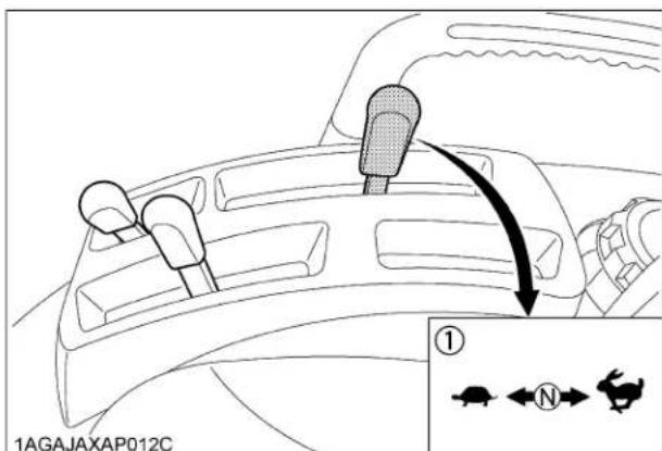
(1) Range gear shift lever (Hi-Lo)
"HIGH"
(N) "NEUTRAL POSITION"
"LOW"
■Front Wheel Drive Lever

CAUTION
To avoid personal injury:
- Do not engage the front wheel drive when traveling at road speed.
- When driving on icy, wet or loose surfaces, make sure the tractor is correctly ballasted to avoid skidding and loss of steering control. Operate at reduced speed and engage front wheel drive.
●An accident may occur if the tractor is suddenly braked, such as by heavy towed loads shifting forward or loss of control.
● The braking characteristics are different between 2 and 4-wheel drive. Be aware of the difference and use carefully.
Use the lever to engage the front wheels with the tractor stopped. Shift the lever to "ON" to engage the front wheel drive.

(1) Front wheel drive lever "ON" "OFF"
IMPORTANT :
● To avoid damage of transmission, when front wheel drive lever is not smoothly shifted, slightly step forward or rearward on speed control pedal.
- Tires will wear quickly if front wheel drive is engaged on paved roads.
◆Front wheel drive is effective for the following jobs:
-
When greater pulling force is needed, such as working in a wet field, when pulling a trailer, or when working with a front-end loader.
-
When working in sandy soil.
-
When working on a hard soil where a rotary tiller might push the tractor forward.
-
Additional braking at reduced speeds.
7. Accelerate the Engine.
■Hand Throttle Lever
Pulling the throttle lever back increases engine speed, and pushing it forward decreases engine speed.
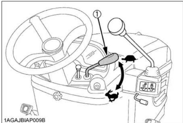
(1) Hand Throttle lever "INCREASE" "DECREASE"
8. Unlock the Parking Brake.
■Parking Brake Pedal
To release the parking brake, depress the brake pedal again.

(1) Brake pedal
9. Depress the Speed Control Pedal.
■Speed Control Pedal

WARNING
To avoid personal injury:
- Do not operate if tractor moves on level ground with foot off Speed Control Pedal.
Forward Pedal
Depress the forward pedal with the toe of your right foot to move forward.
Reverse Pedal
Depress the reverse pedal with the heel of your right foot to move backward.

(1) Speed control pedal
(A) "FORWARD"
(B) "REVERSE"
(2) Stopper bolts
IMPORTANT :
- To prevent serious damage to the HST, do not adjust the stopper bolts.
NOTE :
- When you stand up from the seat with the speed control pedal stepped on, the engine will stop regardless of whether the machine is moving or not. This is because the tractor is equipped with Operator Presence Control system (OPC).
■Speed Set Device
The Speed Set Device is designed for tractor operating efficiency and operator's comfort. This device will provide a constant forward operating speed by mechanically holding the speed control pedal at a selected position.
◆To engage Speed Set Device
- Accelerate speed to desired level using Speed Control Pedal.
- Push and hold the speed set rod downward to "ON" position.
- Release Speed Control Pedal.
- Release the speed set rod and desired speed will be maintained.
◆To disengage Speed Set Device
● Depress the brake pedal.
NOTE :
- If you step on the pedal on the forward acceleration side, the speed set device will disengage.
● Speed set device will not operate in reverse.
IMPORTANT :
- To prevent the damage of speed set device, do not depress the reverse pedal when the speed set device is engaged.
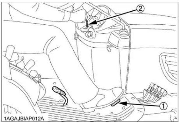
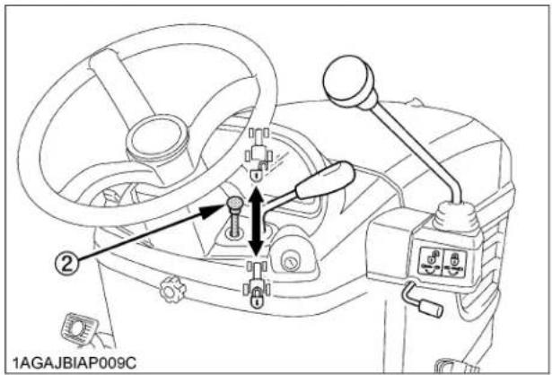
(1) Speed control pedal
(2) Speed set rod "ON"


"OFF"
STOPPING
■Stopping
- Slow the engine down.
- Step on the brake pedal.
- After the tractor has stopped, disengage the PTO, lower the implement to the ground, shift the transmission to "NEUTRAL" and set the parking brake.
CHECK DURING DRIVING
■Immediately Stop the Engine if:
● The engine suddenly slows down or accelerates,
● Unusual noises suddenly are heard,
● Exhaust fumes suddenly become very dark,
While driving, make the following checks to see that all the parts are functioning normally.

(1) Easy checker(TM)
(2) Fuel gauge
(3) Coolant temperature gauge
■Easy Checker(TM)
If the warning lamps in the Easy Checker(TM) come on during operation, immediately stop the engine, and find the cause as shown below.
Never operate the tractor while Easy Checker(TM) lamp is "ON".

Engine oil pressure
If the oil pressure in the engine goes below the prescribed level, the warning lamp in the Easy Checker(TM) will come on.
If this should happen during operation, and it does not go off when the engine is accelerated to more than 1000 rpm, check level of engine oil.
(See "Checking Engine Oil Level" in "DAILY CHECK" in "PERIODIC SERVICE OF THE TRACTOR" section.)

Electrical charge
If the alternator is not charging the battery, the indicator in the Easy Checker(TM) will come on. If this should happen during operation, check the electrical charging system or consult your local KUBOTA Dealer.
NOTE :
- For checking and servicing of your tractor, consult your local KUBOTA Dealer for instructions.
■Fuel Gauge
When the key switch is "ON", the fuel gauge indicates the fuel level.
It's for the check if the gauge is working.
When the fuel is close to empty level, the low fuel indicator of the Easy Checker(TM) comes on and the segment K1 of the fuel gauge starts blinking at 1-second intervals.
Be careful not to empty the fuel tank. Otherwise air may enter the fuel system.
Should this happen, the system should be bled. (See "Bleeding Fuel System" in "SERVICE AS REQUIRED" in "PERIODIC SERVICE OF THE TRACTOR" section.)

(1) Fuel gauge (A) "EMPTY"
(B) "FULL"
(K1) Blinking segment
Coolant Temperature Gauge

CAUTION
To avoid personal injury:
- Do not remove radiator cap until coolant temperature is well below its boiling point. Then loosen cap slightly to the stop to relieve any pressure before removing cap completely.
Overheat indication:
- When the coolant temperature stays at 125 °C for 5 seconds, the indicator on the Easy Checker(TM) comes on.
- When the coolant temperature stays above 130 € for 5 seconds, the indicator remains on and all segments of the coolant temperature gauge start blinking at 1-second intervals.
- When the coolant temperature stays below 120 € for 5 seconds, the indicator turns off.
If the coolant temperature indicator on the Easy Checker(TM) comes on:
- Place the PTO clutch lever in "OFF" (DISENGAGE) position.
- Move the machine to the level surface, and apply the parking brake.
- Place the throttle lever in the engine idle position, and let the engine run for a few minutes.
- Check the Cooling System, after it has sufficient time to cool down.
Check the following items:
- Shortage or leakage of the coolant.
- Foreign matter on the radiator net or dust and dirt between the radiator fins.
- Looseness of fan belt.
- Blockage in the radiator tube. (See "PERIODIC SERVICE OF THE TRACTOR" section.)

(1) Coolant temperature gauge
■Hourmeter/Tachometer
The hourmeter indicates in 6 digits the hours the tractor has been used; the last digit indicates 1/10 of an hour.
When the key is turned "ON", the tachometer should indicate 4000 engine revolutions per minute (rpm) for just a moment.
When the key switch is "ON" and the engine is "ON", the tachometer indicates the engine revolution per minute.

(1) Hourmeter
(2) Tachometer
PARKING
Parking

CAUTION
To avoid personal injury: BEFORE DISMOUNTING TRACTOR
● ALWAYS SET PARKING BRAKE AND LOWER ALL IMPLEMENTS TO THE GROUND.
Leaving transmission in gear with the engine stopped will not prevent the tractor from accidental rolling.
- STOP THE ENGINE AND REMOVE THE KEY.
- When parking, be sure to set the parking brake. To set the parking brake;
(1) Depress the brake pedal.
(2) Latch the brake pedal with the parking brake lock pedal.

(1) Brake pedal
(2) Parking brake lock pedal
(A) "DEPRESS"
(B) "PUSH DOWN (2)
WHILE DEPRESSING (1)"
- Before getting off the tractor, disengage the PTO, lower all implements to the ground, place all control levers in their "NEUTRAL" positions, set the parking brake, stop the engine and remove the key.
- If it is necessary to park on an incline, be sure to chock the wheels to prevent accidental rolling of the machine.
ACCESSORY
■12V Electric Outlet
An auxiliary light or other devices may be connected to this connector.
NOTE :
- Do not connect a light or other device that draws more than 120 watts to this connector, or the battery may discharge very rapidly or the outlet may fail.
IMPORTANT :
- Do not use as a cigarette lighter.
- Do not use when wet.
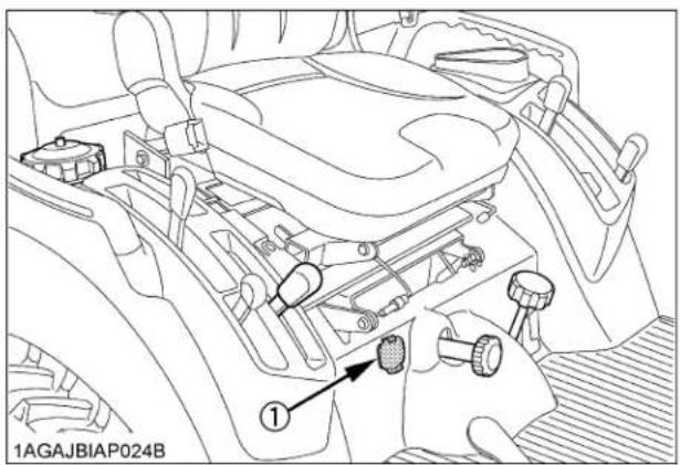
(1) 12V electric outlet
Glove Box

(1) Glove box
OPERATING TECHNIQUES
■Differential Lock

WARNING
To avoid personal injury due to loss of steering control:
- Do not operate the tractor at high speed with differential lock engaged.
- Do not attempt to turn with the differential lock engaged.
- Be sure to release the differential lock before making a turn in field conditions.
If one of the rear wheels should slip, step on the differential lock pedal. Both wheels will then turn together, reducing slippage.
Differential lock is maintained only while the pedal is depressed.
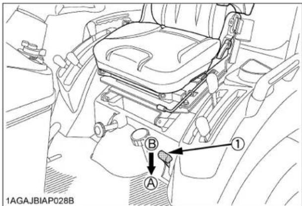
(1) Differential lock pedal (A) Press to "ENGAGE" (B) Release to "DISENGAGE"
IMPORTANT :
- When using the differential lock, always slow the engine down.
● To prevent damage to power train, do not engage differential lock when one wheel is spinning and the other is completely stopped. - If the differential lock cannot be released in the above manner, alternately press speed control pedal forward and backward slightly.
■Operating the Tractor on a Road

CAUTION
To avoid personal injury:
- When traveling on road with 3-point hitch mounted implement attached, be sure to have sufficient front weight on the tractor to maintain steering ability.
Observe all local traffic and safety regulations.
■Operating on a Slopes and Rough Terrain

CAUTION
To avoid personal injury:
● Always back up when going up a steep slope. Driving forward could cause the tractor to tip over backward. Stay off hills and slopes too steep for safe operation.
- Avoid changing gears when climbing or descending a slope.
- If operating on a slope, never disengage shift levers to "NEUTRAL". Doing so could cause loss of control.
- Do not drive the tractor close to the edges of ditches or banks which may collapse under the weight of the tractor. Especially when the ground is loose or wet.
-
Slow down for slopes, rough ground, and sharp turns, especially when transporting heavy, rear mounted equipment.
-
Before descending a slope, be sure that the range lever is in the low "also that speed can be controlled without using brakes.
■Transport the Tractor Safely
- The tractor, if damaged, must be carried on a truck. Secure the tractor tightly with ropes.
-
Follow the instruction below when towing the tractor: Otherwise, the tractor's powertrain may get damaged.
-
Set the all shift levers to "NEUTRAL" position.
- If possible, start engine and select 2WD, if creep speed is fitted ensure that it is disengaged.
● Tow the tractor using its front hitch or drawbar.
● Never tow faster than "10 km/h (6.2 mph)".
■Directions for Use of Power Steering
- Power steering is activated only while the engine is running. While the engine is stopped, the tractor functions in the same manner as tractors without power steering.
- When the steering wheel is turned all the way to the stop, the relief valve is activated. Do not hold the steering wheel in this position for a long period of time.
- Avoid turning the steering wheel while the tractor is stopped, or tires may wear out sooner.
- The power steering mechanism makes the steering easier. Be careful when driving on a road at high speeds.
REVERSING THE SEAT
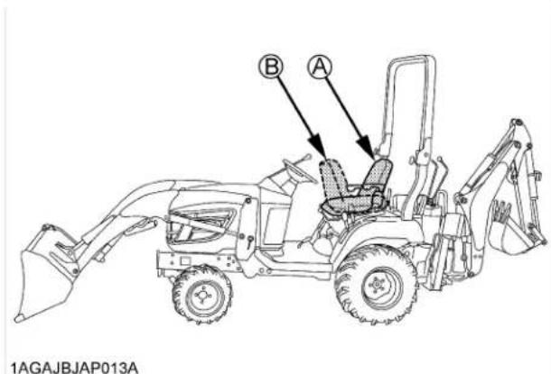
(A) "TRACTOR DRIVING POSITION"
(B) "BACKHOE POSITION"
The seat is reversible for backhoe operation. Follow the procedure below to turn the seat around.
- Loosen the knob nut behind the ROPS and move the bracket left as shown in the illustration.
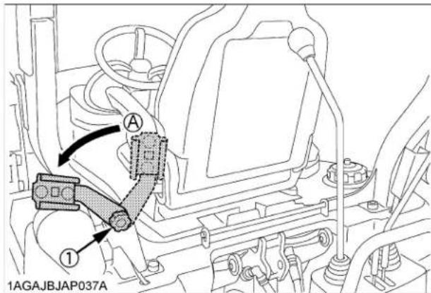
(1) Bracket (A) "LEFT"
- Pull the lever up as shown in the illustration to release the seat lock.

(1) Seat lock lever (A) "RELEASE"
- Raise the seat until the seat pin comes in to the detent notch (see illustration).

natural_image
Line drawing of a car interior showing the steering wheel, suspension lock, and dashboard (no text or symbols)
(1) Seat pin
- Turn the seat around rearward.
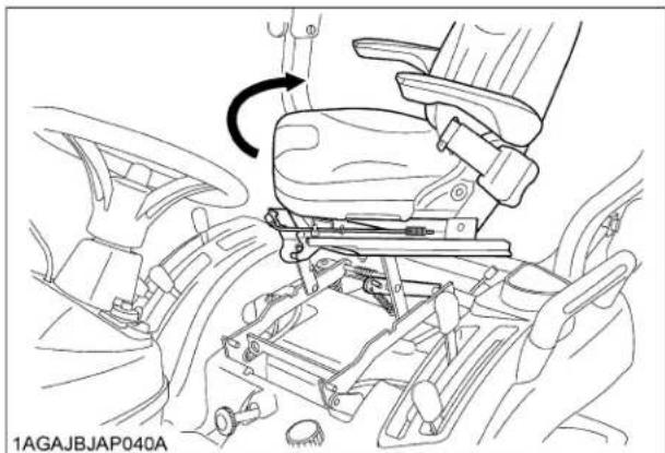
natural_image
Line drawing of a car interior showing a seatbelt mechanism with an arrow indicating rotation (no text or symbols present)- Push the seat backward, then the seat pin will come out from detent notch.
Push the seat down until the lever is locked at the backhoe position.

natural_image
Mechanical assembly diagram showing a car's seatbelt mechanism with directional arrows (no text or symbols)NOTE :
- If the seat pin does not come out from the detent notch, apply grease in the notch.
- After reversing the operator's seat, be sure to check to see that the seat is properly locked.
IMPORTANT :
- Turn the seat at detent position to avoid damage of seat locking mechanism and hitting to the range gear shift lever. - See "Operator's Seat" section when using seat in driving position.
- For tractor driving position, pull the lever up, and follow the reverse procedure mentioned above.
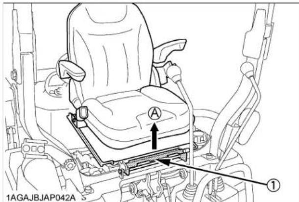
(1) Seat lock lever (A) "RELEASE"
PTO
PTO OPERATION

WARNING
To avoid personal injury:
● Before operation, be sure to select the correct PTO lever (mid, mid/rear, rear).

CAUTION
To avoid personal injury:
● Disengage PTO, stop engine, and allow all rotating components to come to a complete stop before connecting, disconnecting, adjusting, or cleaning any PTO driven equipment.
■PTO Select Lever
The tractor has a 540 rpm rear PTO speed and a 2500 rpm mid-PTO speed.

(1) PTO select lever (A) Mid-PTO position
(B) Mid-Rear-PTO position
(C) Rear-PTO position
◆Mid-PTO
To use Mid-PTO, shift the PTO select lever to Mid-PTO position and the PTO clutch lever to "ON" position.
◆Mid-Rear PTO
To use mid and rear PTO at the same time, shift the PTO select lever to mid-rear PTO position and the PTO clutch lever to "ON" position.
◆Rear PTO
To use rear PTO, shift the PTO select lever to rear PTO position and the PTO clutch lever to "ON" position.
IMPORTANT :
● To avoid shock loads to the PTO, reduce engine throttle from full to half speed by pushing up on engine throttle when engaging the PTO, then open the throttle to full.
● To avoid damage of transmission, when PTO select lever is not smoothly shifted, slightly shift PTO clutch lever.
◆Mid-PTO
The Mid-PTO is available for KUBOTA approved implements.

(1) Mid-PTO
■PTO Clutch Lever
- The PTO clutch lever engages or disengages the PTO clutch which gives the PTO independent control.
- Shift the lever to "ON" to engage the PTO clutch. Shift the lever to "OFF" to disengage the PTO clutch.
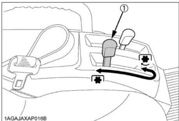
(1) PTO clutch lever "ON" "ENGAGE"
"OFF" "DISENGAGE"
IMPORTANT :
● To avoid shock loads to the PTO, reduce engine throttle from full to half speed by pushing up on engine throttle when engaging the PTO, then re-engage the engine to full.
● To avoid damage to PTO clutch and implement, shift the PTO clutch lever slowly, when engaging the PTO clutch. Do not keep the PTO clutch lever half way.
NOTE :
● Tractor engine will not start if the PTO clutch lever is in the engaged "ON" position.
- When you stand up from the seat with the PTO clutch lever at "ON" (Engaged) position, the engine will stop regardless of the position of the PTO select lever. This is because the tractor is equipped with Operator Presence Control system (OPC).
■PTO Shaft Cover and Shaft Cap
Keep the PTO shaft cover in place at all times. Replace the PTO shaft cap when the PTO is not in use. Before connecting or disconnecting a drive shaft to PTO shaft, be sure engine is "OFF" and raise up the PTO shaft cover.
Afterward be sure to return the PTO shaft cover to "NORMAL POSITION".

(1) PTO shaft cover
(2) PTO shaft cap
(A) "NORMAL POSITION"
(B) "RAISED POSITION"
IMPORTANT :
● The universal joint of the PTO drive shaft is technically limited in its moving angle. Refer to the PTO Drive Shaft Instructions for proper use.
■Stationary PTO
To park the tractor and use the PTO system (for chipper or pump, for example), start the PTO system in the following steps.
- Apply the parking brakes and place blocks at the tires.
- Make sure all shift levers are at "NEUTRAL", and start the engine.
- Set the PTO gear shift lever to engage "ON".
- Set the engine speed to provide recommended rear PTO speed.
- Unlock the seat lock lever and stand up and raise the seat.

(1) Seat lock lever
- Turn the seat around rearward and lock the seat at backhoe position. (See "REVERSING THE SEAT" in "OPERATING THE TRACTOR" section.)
■PTO Drive Shaft
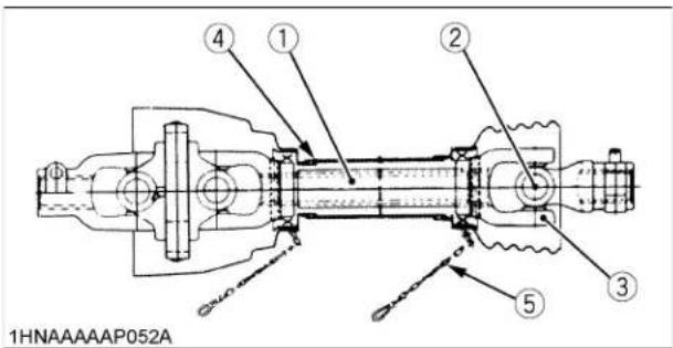
(1) Inner and outer sliding profile tubes
(2) Journal cross assy
(3) Fitting yoke
(4) Safety guard (In, Out)
(5) Chain
- When using a PTO drive shaft, read the operator's manual of the implement before operating the implement.
PTO drive shafts are designed for specific machines and power requirement.
- To adjust the length of the PTO drive shaft, refer to the following instructions.
(1) To adjust the length, hold the half shafts next to each other in the shortest working position and mark them.
(2) Shorten inner and outer guard tubes equally.
(3) Shorten inner and outer sliding profiles tube by the same length as the guard tubes.
(4) Round off all sharp edges and remove burrs. Grease sliding profiles.


natural_image
Line drawing of hands operating a mechanical device (no text or symbols visible)
natural_image
Illustration of a hand using a tool to cut a cylindrical object into a frame (no text or symbols visible)
- Ensure that the PTO drive shaft is securely connected at both ends before operating.

3-POINT HITCH & DRAWBAR

Use holder plate to hold lower link higher while mowing with mid-mount mower only over uneven terrain.
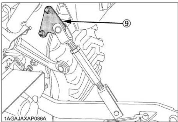
(9) Holder plate
(1) Top link
(2) Lifting rod (Left)
(3) Check chains
(4) Turnbuckle
(5) Lower link
(6) Top link holder
(7) Lifting rod (Right)
(8) Drawbar
(9) Holder plate
3-POINT HITCH
■Attaching and detaching implements

CAUTION
To avoid personal injury:
- Be sure to stop the engine and remove the key.
- Do not stand between tractor and implement unless parking brake is applied.
● Before attaching or detaching implement, locate the tractor and implement on a firm, flat and level surface. - Whenever an implement or other attachment is connected to the tractor 3-point hitch, slowly move the 3-point hitch through the full range of operation and check for interference, binding or PTO separation before operating the machine.
■Lifting Rod (Right)

CAUTION
To avoid personal injury from separation:
- Do not extend lift rod beyond the groove on the threaded rod or it may separate. See the illustration that is on the safety label part K2581-6555-1.
Level a 3-point mounted implement from side to side by turning the adjusting turnbuckle to shorten or lengthen the adjustable lifting rod with the implement on the ground.
After adjustment, tighten the lock nut securely.
Do not extend lift rod beyond the groove on the threaded rod when extending it.

(1) Adjusting turnbuckle
(A) Groove
(2) Lock nut
■Top Link
-
Adjust the angle of the implement to the desired position by shortening or lengthening the top link.
-
The proper length of the top link varies according to the type of implement being used.
NOTE :
- When not using the top link, make it the shortest length and fix it to the top link holder.
Check Chains
Make sure that the check chains are installed in the figures below.
Adjust the turnbuckle to control horizontal sway of the implement.
After adjustment, retighten the lock nut.

(1) Turnbuckle
(2) Lock nut
HITCH

WARNING
To avoid personal injury:
● Never pull from the top link, the rear axle or any point above the hitch. Doing so could cause the tractor to tip over rearward causing personal injury or death.

(1) Hitch
■Removing the 3-Point Hitch
When installing the backhoe, remove the 3-point hitch.
-
Remove the lynch pin and the top link pin. Then remove the top link.
-
Remove the snap ring and the clevis pin. Then remove the left and right lifting rod.
-
Remove the hair pin and stopper pin. Then remove the check chain plate and lower links.
■Installing the 3-Point Hitch
- Follow the reverse procedure mentioned above.

(1) Top link
(7) Hair pin
(2) Clevis pin
(8) Check chain plate
(3) Snap ring
(9) Top link pin
(4) Lifting rod (Left)
(10) Lynch pin
(5) Lower link
(11) Lifting rod (Right)
(6) Stopper pin
HYDRAULIC UNIT
3-POINT HITCH CONTROL SYSTEM

CAUTION
To avoid personal injury:
● Before using the 3-point hitch controls, ensure that no person or object is in the area of the implement or 3-point hitch. Do not stand on or near the implement or between the implement and tractor when operating the 3-point hitch controls.
Hydraulic Control
Operating the hydraulic control lever actuates the hydraulic lift arm, which controls the elevation of 3-point hitch mounted implement.
To lower implement, move the hydraulic control lever forward; to raise it, move the hydraulic control lever rearward.
The positions (B) and (C) of the lever in contact with the inner stopper enables you to control the valve with ease in increments of approximately 6.4mm at the lower link end.
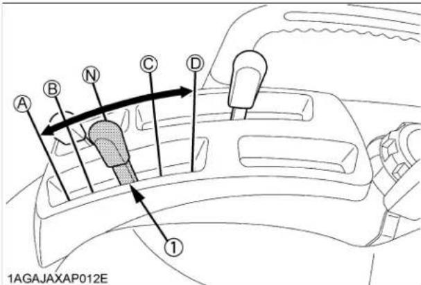
(1) Hydraulic control lever (A) "DOWN"
(B) "SLOW DOWN"
(N) "NEUTRAL"
(C) "SLOW UP"
(D) "UP"
IMPORTANT :
- If the 3-point hitch can not be raised by setting the hydraulic control lever to the "UP" position after long term storage or when changing the transmission oil, follow these air bleeding procedures.
(1) Stop the engine.
(2) Set the hydraulic control lever to the down position and start the engine.
(3) Operate the engine at low idle speed for at least 30 seconds to bleed air from the system.
- Do not operate until the engine is warmed up. If operation is attempted when the engine is still cold, the hydraulic system may be damaged.
- If noises are heard when implement is lifting after the hydraulic control lever has been activated, the hydraulic mechanism is not adjusted properly. Unless corrected the unit will be damaged. Contact your KUBOTA Dealer for adjustment.
■3-point Hitch Lowering Speed

CAUTION
To avoid personal injury:
● Fast lowering speed may cause damage or injury. Lowering speed of implement should be adjusted to 2 or more seconds.
The lowering speed of the 3-point hitch can be controlled or locked in similar fashion to a water faucet, turn toward (A) to increase, (B) to reduce and (C) firmly to the stop for lock.

(1) 3-point hitch lowering speed knob (A) "FAST"
(B) "SLOW"
(C) "LOCK"
AUXILIARY HYDRAULICS
On the tractor hydraulic outlet is provided.

CAUTION
To avoid serious personal injury:
● Escaping hydraulic fluid under pressure can have sufficient force to penetrate skin, causing serious personal injury.
Before disconnecting lines, be sure to relieve all pressure.
Before applying pressure to system, be sure all connections are tight and that lines, tubes and hoses are not damaged.
Fluid escaping from a very small hole can be almost invisible. Use a piece of cardboard or wood, rather than hands to search for suspected leaks.
If injured by escaping fluid, see a doctor at once. Serious infection or allergic reaction will develop if proper medical treatment is not administered immediately.
Hydraulic Outlet
It can be used with the BT602 Backhoe.
When mounting the backhoe.
- Disconnect the coupler.

(1) Coupler
- Route the implement inlet, outlet, and power beyond hose as shown in the illustration.

(1) Inlet hose (backhoe)
(2) Outlet hose (backhoe)
(3) Power beyond hose (backhoe)
(4) Outlet hose (tractor)
(5) Return pipe (tractor)
(6) Power beyond pipe (tractor)
(A) To Backhoe (outlet)
Max. flow
14 L/min.
(B) From Backhoe (inlet)
(C) Return to tank
IMPORTANT :
- For hydraulic outlet, be sure to use the control valve of the "Power beyond type" (with relief valve) and third line return to tank for the operation of hydraulic block.
INSTALLING MOWER
Do not attach nor operate the mower with the backhoe still in place.
When installing the mower, remove the backhoe from the tractor with following procedure.

CAUTION
To avoid serious personal injury:
● Escaping hydraulic fluid under pressure can have sufficient force to penetrate skin, causing serious personal injury.
Before disconnecting lines, be sure to relieve all pressure.
Before applying pressure to system, be sure all connections are tight and that lines, tubes and hoses are not damaged.
Fluid escaping from a very small hole can be almost invisible. Use a piece of cardboard or wood, rather than hands to search for suspected leaks.
If injured by escaping fluid, see a doctor at once. Serious infection or allergic reaction will develop if proper medical treatment is not administered immediately.
◆Disconnecting and connecting the hoses
- Shut the engine off and set the parking brake.
- Tilt the operator's seat forward.
- Remove hydraulic pressure by moving the controls.
- Disconnect the backhoe inlet hose, outlet hose and power beyond hose.

(1) Inlet hose (backhoe)
(2) Outlet hose (backhoe)
(3) Power beyond hose (backhoe)
(4) Outlet hose (tractor)
- Place the protective cap on the coupler of the backhoe inlet hose, the coupler of the outlet hose, and power beyond hose.
- Connect the tractor outlet hose to the coupler of power beyond pipe.

(1) Outlet hose (tractor) (A) To be connected
(2) Power beyond pipe (tractor)
- Place the protective cap on the nipple of the tractor return pipe.
NOTE :
- When getting ready to use the backhoe after finishing mowing, connect the hoses of the tractor and backhoe in reverse order.
■Cutting Height Control Dial
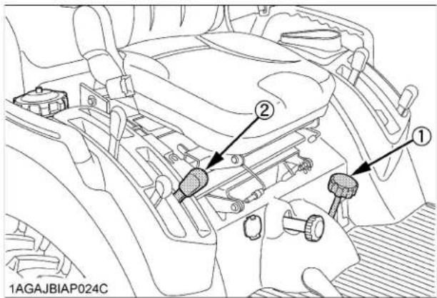
(1) Cutting height control dial
(2) Hydraulic control lever

(1) Mower rear link
When mounting the Mid-mount mower, turn the cutting height control dial to the desired height.
For further details, refer to the operator's manual of ROTARY MOWER RCK60B-23BX, RCK54P-23BX and RCK54-23BX.
IMPORTANT :
When operating the tractor without Mid-mount mower:
- Move the hydraulic lever rearward to raise the mower rear links to the highest position.
- Set the cutting height control dial to "TOP" position.
If this is not done, damage of the mower rear link can result.
■Hydraulic Control Unit Use Reference Chart
In order to handle the hydraulics properly, the operator must be familiar with the following. Though this information may not be applicable to all types of implements and soil conditions, it is useful for general conditions.
| Implement |  Soil condition Soil condition |  (1) Hydraulic control lever (1) Hydraulic control lever |  1AGAECAP0590 Gauge wheel 1AGAECAP0590 Gauge wheel | 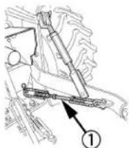 1AGAJAXAP057C (1) Check chains 1AGAJAXAP057C (1) Check chains | Remarks |
| Moldboard plow | Light soil Medium soil Heavy soil | Hydraulic control | YES/NO Loose | Adjust the check chains so that the implement can move 5 to 6 cm laterally. Check chains should be tight enough to prevent excessive implement movement when implement is in raised position. | |
| Disc plow --- | |||||
| Harrower (spike, springtooth, disc type) | --- | ||||
| Sub-soiler..... | |||||
| Weeder, ridger..... | --- | YES | Tighten | ||
| Earthmove, digger scraper, manure fork rear carrier.... | YES/NO | For implements with gauge wheels, lower the position control lever all way. | |||
| Mower (mid-and rear-mount type) Hayrake, tedder... |
| Implement | Soil condition | 1AGAJAXAP012F(1) Hydraulic control lever | 1AGAEBCAP0590Gauge wheel | 1AGAJAXAP057C(1) Check chains | Remarks |
| Moldboard plow | Light soilMedium soilHeavy soil | Hydraulic control | YES/NO Loose | Adjust the check chains so that the implement can move 5 to 6 cm laterally.Check chains should be tight enough to prevent excessive implement movement when implement is in raised position. | |
| Disc plow --- | |||||
| Harrower (spike, springtooth, disc type) | --- | ||||
| Sub-soiler..... | |||||
| Weeder, ridger..... | --- | YES | Tighten | ||
| Earthmove, digger scraper, manure fork rear carrier.... | YES/NO | For implements with gauge wheels, lower the position control lever all way. | |||
| Mower (mid-and rear-mount type)Hayrake, tedder... |
TIRES, WHEELS AND BALLAST
TIRES

WARNING
To avoid personal injury:
- Do not attempt to mount a tire on a rim. This should be done by a qualified person with the proper equipment.
● Always maintain the correct tire pressure. Do not inflate tires above the recommended pressure shown in the operator's manual.
IMPORTANT :
- Do not use tires other than those approved by KUBOTA.
- When you intend to mount different size of tires from equipped ones, consult your dealer about front drive gear ratio for details.
Excessive wear of tires may occur due to improper gear ratio.
Inflation Pressure
Though the tire pressure is factory-set to the prescribed level, it naturally drops slowly in the course of time. Thus, check it everyday and inflate as necessary.
| Tire sizes Inflation Pressure | ||
| Rear | 26x12.00-12 Turf | 100kPa(1.0kgf/ Ωm2 |
| 26x12.00-12 Bar | 120kPa(1.2kgf/ Ωm2 | |
| 26x12.00-12 Ind. | 120kPa(1.2kgf/ Ωm2 | |
| Front | 18x8.50-10 Turf | 120kPa(1.2kgf/ Ωm2 |
| 18x8.50-10 Bar | 150kPa(1.5kgf/ Ωm2 | |
| 18x8.50-10 Ind. | 150kPa(1.5kgf/ Ωm2 | |
NOTE :
- Maintain the maximum pressure in front tires, if using a front loader or when equipped with a full load of front weight.
Dual Tires
Dual tires are not approved.
WHEEL TREAD

CAUTION
To avoid personal injury:
● Support tractor securely on stands before removing a wheel.
- Never operate tractor with a loose rim, wheel, or axle.
Front Wheels
Front tread can not be adjusted.
IMPORTANT :
- Do not turn front discs to obtain wider tread.
| Tire 18x8.50-10 Turf, Bar, and Ind. | |
| Tread | 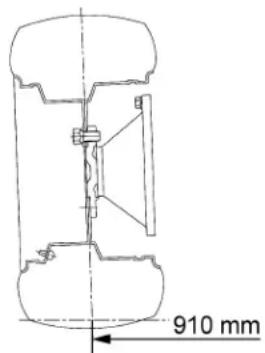 1AGAJAXAP075C 1AGAJAXAP075C |

CAUTION
To avoid personal injury:
● Before jacking up the tractor, park it on a firm and level ground and chock the rear wheels.
● Fix the front axle to keep it from swinging.
- Select jacks that withstand the machine weight and set them up as shown below.
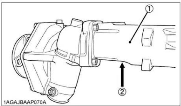
(1) Front axle case
(2) Jack points
Rear Wheels
Rear tread width can not be adjusted.
IMPORTANT :
- Do not turn rear discs to obtain wider tread.
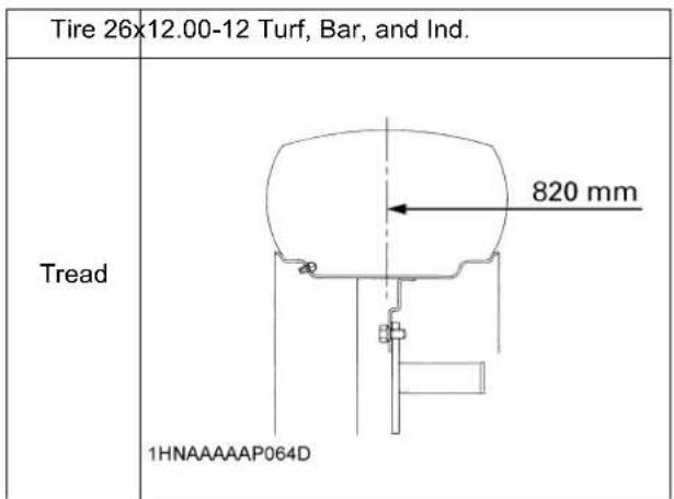
IMPORTANT :
● Always attach tires as shown in the drawings.
- If not attached as illustrated, transmission parts may be damaged. When re-fitting or adjusting a wheel, tighten the bolts to the following torques then recheck after driving the tractor 200m (200yards), after one day (8 hours) and thereafter every 50 hours (as per maintenance chart).
NOTE :
- Use the tapered bolts for wheels with beveled or tapered holes.

(1) Bolt Front 149.2 to 179.0 N-m
(15.2 to 18.3 kgf-m)
Rear 108.5 to 130.2 N-m
(11.1 to 13.3 kgf-m)

CAUTION
To avoid personal injury:
● Before jacking up the tractor, park it on a firm and level ground and chock the front wheels.
● Fix the front axle to keep it from swinging.
- Select a jack that withstands the machine weight and set it up as shown below.
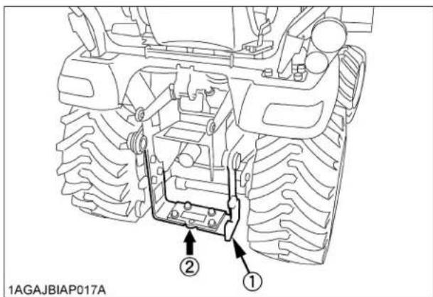
(1) Frame
(2) Jack point
BALLAST

CAUTION
To avoid personal injury:
● Additional ballast will be needed for transporting heavy implements. When the implement is raised, drive slowly over rough ground, regardless of how much ballast is used.
- Do not fill the front wheels with liquid to maintain steering control.
NOTE :
● The ballast is not required when doing the normal operations with the BX25DLB tractor, LA240A loader, LA240A AU-SG loader and BT602 backhoe connected in factory settings.
Front Ballast
Add weights if needed for stability and improve traction.
Heavy pulling and heavy rear mounted implements tend to lift front wheels. Add enough ballast to maintain steering control and prevent tip over.
Remove weight when no longer needed.
IMPORTANT :
- Do not overload tires.
- Add no more weight than indicated in chart.
| Maximum weight 125 kg |
■Rear Ballast
[Standard model]

CAUTION
To avoid personal injury:
- For tractor stability and operator's safety, rear ballast should be added to the rear of the tractor in the form of 3-point counter weight and rear wheel ballast. The amount of rear ballast will depend on the application.
| Implement as Counter Weight | |
| Box Blade | Approx. 190 kg |
| Rear Blade | |
| Rotary Tiller | |
| Ballast Box | |
◆Liquid ballast in rear tires
Water and calcium chloride solution provides a safe and economical ballast. Used properly, it will not damage tires, tubes or rims. The addition of calcium chloride is recommended to prevent the water from freezing. Use of this method of weighting the wheels has full approval of the tire manufacturers. See your tire dealer for this service.
Liquid weight per tire (75 Percent filled)
| Tire sizes 26 x 12-12 | |
| Slush free at -10 °CSolid at -30 °C[Approx. 1 kg CaCl2 per 4 L of water] | 45 kg |
| Slush free at -24 °CSolid at -47 °C[Approx. 1.5 kg CaCl2 per 4 L of water] | 50 kg |
| Slush free at -47 °CSolid at -52 °C[Approx. 2.25 kg CaCl2 per 4 L of water] | 56 kg |
NOTE :
- When mounting a heavy implement, a liquid in the tire may not be required.
IMPORTANT :
- Do not fill tires with water or solution more than 75% of full capacity (to the level of valve stem at 12 o'clock position).

(1) Air
(A) Correct : 75% Full
(2) Water
Air compresses like a cushion
(3) Valve stem
(B) Incorrect : 100% Full
Water can not be compressed
● To avoid damage of transmission, do not use rear wheel weights and liquid ballast at the same time.
- Do not add liquid ballast or any other weights to the front tires.
● While BT602 backhoe is installed on the tractor, liquid ballast in the rear tires should be removed.
[Spill guard model]
![KUBOTA LA240A - [Spill guard model] - 1](/content/2026/05/991150/images/9ed057993838535c043a8b0aced18a4362ff352a783554a84f2018ab84fbee3f.jpg)
WARNING
To avoid personal injury or death:
- Do not exceed ROL (Rated operation load).
- Do not operate the loader without counter weight.
- Do not exceed 10 km/h when travelling with load.
- ROL is calculated with standard bucket. Optional attachments (4IN1 bucket etc.) will reduce ROL.
[With counter weight]
| Rated operation load (ROL) | 190 kg |
| Counter weight required *1 | 70 kg |
[With backhoe]
| Rated operation load (ROL) | 220 kg |
*Be sure to install the counter weight approved by KUBOTA.
The use of a counter weight significantly reduces the front axle and tire load during loader operation. It also increases the fore/aft stability of the tractor/loader by shifting weight from the front axle to the rear axle. Failure to use the recommended counter weight can result in damage to the tractor, reduced braking capability, and instability of the tractor/loader.

natural_image
Technical line drawing of an electrical enclosure with four switches and a labeled component (no text or symbols on the diagram itself)(1) Counter weight
IMPORTANT :
● Water ballasting the rear tires of the tractor does not reduce the front axle load.
The loader should be operated with the tractor engine speed depending on the application and the operator's level of experience. Excessive speeds are dangerous, and may cause bucket spillage and unnecessary strain on the tractor and loader.
When operating in temperatures below -1°C, run the tractor engine below 1200 rpm until the oil temperature exceeds -1°C.
The following text and illustrations offer suggested loader and tractor operating techniques.

CAUTION
To reduce the possibility of roll over:
- It is not recommended that the loader be attached when operating another implement on a hillside.
IMPORTANT :
- When operating the loader in rough terrain, remove the mower to avoid damage to the mower.
FILLING THE BUCKET
Approach and enter the pile with a level bucket.
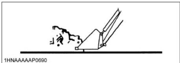
natural_image
Diagram of a mechanical device with a broken surface and a triangular base, showing no text or symbols.Ease control lever toward you and then left to rollback and lift the bucket.

The rollback and lifting of the bucket will increase efficiency because a level bucket throughout the lifting cycle resists bucket lift and increases breakaway effort.
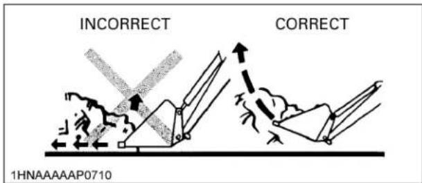
NOTE :
- Do not be concerned if the bucket is not completely filled during each pass. Maximum productivity is determined by the amount of material loaded in a given period of time. Time is lost if 2 or more attempts are made to fill the bucket on each pass.
LIFTING THE LOAD
When lifting the load, keep the bucket positioned to avoid spillage.


WARNING
To avoid serious personal injury:
- Do not attempt to lift bucket loads in excess of the loader capacity.
● Before raising the bucket to full height, make sure the tractor is on level ground. If not, it may tip over, even if the tractor is not moving.
CARRYING THE LOAD
Position the bucket just below the level of the tractor hood for maximum stability and visibility, whether the bucket is loaded or empty.

natural_image
Line drawing of a tractor with attached tractors, no text or symbols presentUse extreme care when operating the loader on a slope. Keep the bucket as low as possible. This keeps the bucket and tractor center of gravity low and will provide maximum tractor stability.

WARNING
To avoid serious personal injury:
● Be extra careful when working on inclines.
- When operating on a slope, always operate up and down the slope, never across the slope.

When transporting a load, keep the bucket as low as possible to avoid tipping, in case a wheel drops in a rut.

DUMPING THE BUCKET
Lift the bucket just high enough to clear the side of the vehicle. Move the tractor in as close to the side of the vehicle as possible, then dump the bucket.
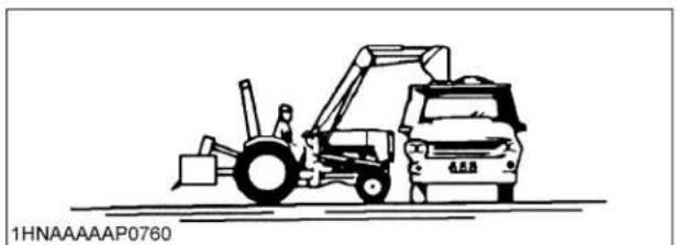
natural_image
Line drawing of a front-end loader and dump truck (no text or symbols)LOWERING THE BUCKET
After the bucket is dumped, back away from the vehicle while lowering and rolling back the bucket.

flowchart
graph TD
    A["FLOAT"] --> B["DOWN"]
    B --> C["DOWN & DUMP"]
    C --> D["DUMP"]
    D --> E["UP & DUMP"]
    E --> F["UP"]
    F --> G["ROLL BACK"]
    G --> H["DOWN & ROLL BACK"]
    H --> I["ROLL BACK"]
    I --> J["1HNAAAAAP0770"]
OPERATING WITH FLOAT CONTROL
During operation on hard surface, keep the bucket level and put the lift control in the float position to permit the bucket to float on the working surface. If hydraulic down pressure is exerted on the bucket it will wear faster than normal.

The float position will also avoid mixing of surface material with stockpile material. The float position will reduce the chance of surface gouging while removing snow or other material, or when working with a blade.

LOADING FROM A BANK
Choose a forward gear that provides a safe ground speed and power for loading.

natural_image
Line drawing of a tractor pulling a large pile of hay or gravel, with no text or symbols present.
WARNING
To avoid the possibility of serious personal injury:
● Exercise caution when undercutting high banks.
- Dirt slides can be dangerous. Load from as low as possible for maximum efficiency.
NOTE :
- Loader lift and break-away capacity diminish as loading height is increased.

Side cutting is a good technique for cutting down a big pile. Wheel width should not exceed the bucket width for this procedure.

natural_image
Line drawing of a front-end loader dumping material into a pile (no text or symbols)If the pile sides are too high and liable to cause cave-in, use the loader to break down the sides until a slot can be cut over the top.

natural_image
Line drawing of a tractor pulling a heavy truck through a mountain slope (no text or symbols)Another method for large dirt piles is to build a ramp to approach the pile.

It is important to keep the bucket level when approaching a bank or pile. This will help avoid gouging the work area.
PEELING AND SCRAPING
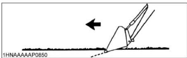
Use a slight bucket down angle, travel forward, and hold the lift control forward to start the cut. Make a short cut and break-out cleanly.
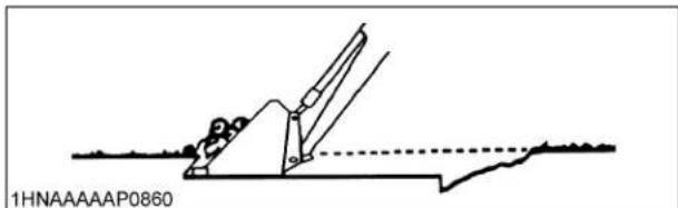
natural_image
Technical line drawing of a mechanical assembly or lifting mechanism (no text or symbols)With the bucket level, start a cut at the notch approximately 5 cm. deep. Hold the depth by feathering the bucket control to adjust the cutting edge up or down. When the front tires enter the notch, adjust the boom cylinder to maintain proper depth.

Make additional passes until the desired depth is reached. During each pass, use only the bucket control while at working depth. This will allow you to concentrate on controlling the bucket angle to maintain a precise cut.
LOADING LOW TRUCKS OR SPREADERS FROM A PILE

natural_image
Top-down line drawing of a car and a truck with exhaust smoke, no text or symbols presentFor faster loading, minimize the angle of turn and length of run between pile and spreader.

natural_image
Diagram of a tractor pulling a plow with an arrow indicating direction (no text or symbols on the diagram itself)Back grade occasionally with a loaded bucket to keep the work surface free of nuts and holes. Also, hold the lift control forward so the full weight of the bucket is scraping the ground. Use the heel of the bucket.
BACKFILLING

Approach the pile with the bucket flat.

Poor operating methods will move less dirt and make it more difficult to hold a level grade.
IMPORTANT :
- Do not use the bucket in the dumped position for bulldozing. As shown above, this method will impose severe shock loads on the dump-linkage, the bucket cylinders, and the tractor.

Leave dirt in the bucket because dumping on each pass wastes time.
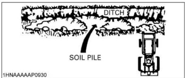
Operate at right angles to the ditch. Taking as big a bite as the tractor can handle.
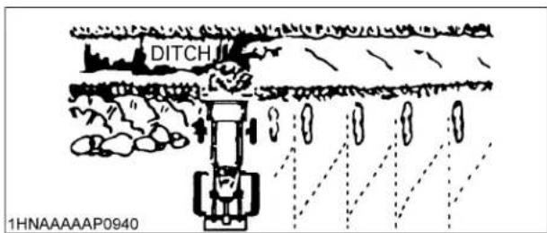
Leave dirt which drifts over the side of the bucket for final cleanup.

natural_image
Illustration of a tractor pulling crops on a slope with a falling pipe, no text or symbols presentPile dirt on the high side for easier backfilling on a slope.
HANDLING LARGE HEAVY OBJECTS

DANGER
To avoid serious personal injury or death:
● Handling large, heavy objects can be dangerous due to :
(A) Danger of rolling the tractor over.
(B) Danger of upending the tractor.
(C) Danger of the object rolling or sliding down the loader boom onto the operator.
- If you must perform the above work, protect yourself by :
(A) Not lifting the load higher than necessary to clear the ground when moving.
(B) Ensuring the approved counter weight is fitted.
(C) Not lifting large objects with equipment that does not have an anti-rollback device.
(D) Moving slowly and carefully.
(E) Avoiding rough terrain.
(F) Keeping transport distance as short as possible and carry the load as low as possible during transport.
(G) Ensuring that the ROL for the given attachment is not exceeded.
VALVE LOCK

CAUTION
To avoid injury from crushing:
- Do not utilize the valve lock for machine maintenance or repair.
● The valve lock is to prevent accidental actuation when implement is not in use or during transport.
The control valve is equipped with a valve lock feature. The control valve is locked in "NEUTRAL" position.
The lock is not intended and will not prevent a leak down of the implement during the period of storage.

(1) Lock lever (A) "LOCK"
(B) "UNLOCK"
■Boom Lock (Spill guard model only)

WARNING
To avoid personal injury or death:
- Before setting the boom lock -empty the loader bucket and place in dump position, -park on a firm, flat and level surface, -set the parking brake, -stop the engine and remove the key, -set the valve lock.
The boom lock is used to prevent the loader lift arms from falling when servicing the machine, set as follows.
[To Set the Boom Lock]
- Empty the loader bucket and place in dump position.
- Raise the boom until the boom lock can be positioned on the cylinder.
- Stop the engine and remove the key.
- Set the valve lock lever to lock position.
- Set the boom lock to the cylinder rod.
- Insert the lock pin into the hole of the boom lock.
- Set the valve lock lever to unlock position.
- Slowly lower the boom until stopped and set the valve lock lever to lock position.


(1) Boom lock
(2) Lock pin
(3) Snap pin
[To Remove the Boom Lock]
- Raise the boom until the boom lock can be removed from the cylinder.
- Stop the engine and remove the key.
- Set the valve lock lever to lock position.
- Remove the lock pin from the boom lock.
- Remove the boom lock from the boom cylinder.
- Set the valve lock lever to unlock position.
- Slowly lower the boom to the ground level.
◆Storing the boom lock
- Attach the boom lock to the stay. Fix the boom lock with the knob bolts, lock pin and snap pin.
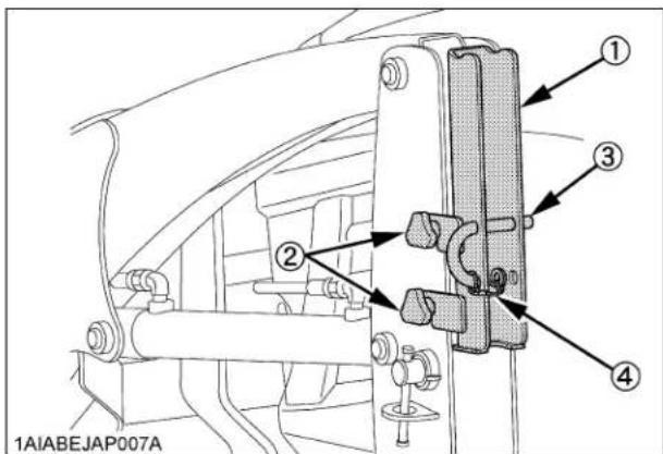
(1) Boom lock
(2) 2-Knob bolts
(3) Lock pin
(4) Snap pin
IMPORTANT :
● Never use hydraulic power (engine running) to lower the boom onto the boom lock.
SPILL GUARD (SPILL GUARD MODEL ONLY)
The spill guard system prevents the object in the bucket from falling to the operator's space.
When the operator operates the control lever to the roll back position at the upper most boom position, this system restricts the bucket roll back movement.
IMPORTANT :
- Check the motion of spill guard function, before operating the loader.
During operation, the spill guard will operate from the point equal to or higher than height (L).

(L) 700 mm
■Adjustment of spill guard link

CAUTION
To avoid personal injury:
- Keep your hand away from links or boom when operating the loader.
- Start engine and lift the boom to appointed height (L).
- Rolled back the bucket fully and check the rollback angle (A).
- If the rollback angle is not the same as following illustration, adjust the length of connecting rod.

(A) 45irc
(L) Highest position
◆Adjustment of spill guard link
- Remove the cotter pin.
- Remove the rod from the link.
- Unfasten the lock nut and adjust the length of connecting rod by turning rod.
| Condition of the bucket at appointed height | Adjustment |
| Bucket rolled back too far | Shorten connecting rod |
| Bucket dumped too far | lengthen connecting rod |
- Tighten the lock nut and set the rod to the link with the cotter pin.

(1) Link
(2) Connecting rod
(3) Lock nut
(4) Cotter pin
(5) Rod
ATTACHING ATTACHMENTS
[Option for LA240A, LA240A AU-SG]
NOTE :
- Attachments should be located on a flat, firm surface when attaching and detaching them from the BX6315 or LA243A AU-SG Quick Coupler.
- Remove Hitch Pins and Snapper Pins from the Hitch Pin Bosses on the BX6315 or LA243A AU-SG Quick Coupler.
- Move the loader control lever to the "dump" position until the surface with the arrow marker on the BX6315 or LA243A AU-SG Quick Coupler label gets in parallel with the ground as shown in the following illustration.
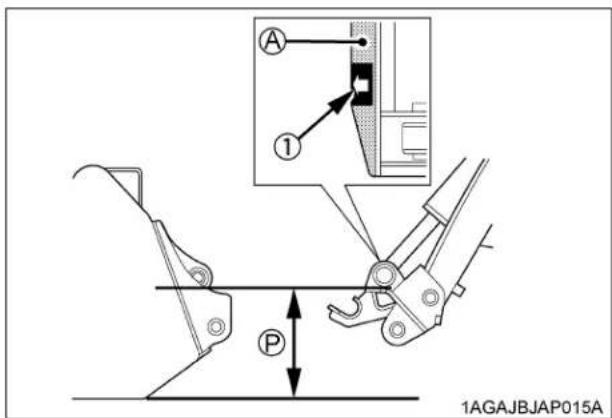
(1) Arrow marker (A) Position this surface in parallel with the ground. (P) "PARALLEL"
- Move the tractor forward slowly until the arrow marker on the attachment label is close to that on the Quick Coupler label.
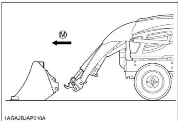
(M) "MOVE FORWARD SLOWLY"
[When viewed from the operator's seat]

(A) Front attachment side
(B) Quick Coupler side
- Raise the boom of the loader until the pin at the upper bosses of the attachment seat in the Quick Coupler receivers, and the rear of the attachment is raised slightly off the ground.

(1) Pin 3 (U) "UP" position

CAUTION
To avoid personal injury:
- Do not raise attachment completely off the ground at this point. the attachment could swing off the quick coupler.
- Keeping the attachment at ground level, move the loader control lever to the "roll back" position until the cylinders stop. Turn off the engine and set the parking brake.
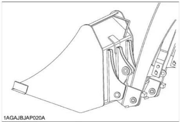
natural_image
Technical line drawing of a mechanical assembly with no visible text or symbols- Install both Hitch Pins and Snapper Pins as shown in the following illustration.
The illustration shows a properly attached bucket.

(A) Hitch Pins
(B) Snapper Pins

CAUTION
To avoid personal injury:
● Make sure both hitch pins and snapper pins are properly installed before moving or operating attachments.
- Keep hitch pins and snapper pins assembled in the BX6315 or LA243A AU-SG quick coupler at all times, even if no attachment is being used.
- Replace any pins or other parts which are lost or broken.
- You are now ready to use the attached attachment. Compatible attachments can be attached and detached using the same method.

CAUTION
To avoid personal injury:
● Never operate or transport attachments which are not attached completely.
● Always replace damaged hardware immediately.
DETACHING ATTACHMENTS
[Option for LA240A, LA240A AU-SG]
- Detaching the attachments is done in the reverse of attaching attachments.
- Lower the implement and roll it back completely. Stop the engine and set the parking brake.
- Remove Hitch Pins and Snapper Pins.
- While sitting in the tractor operator's seat, start the engine and slowly move the loader control lever to the "dump" position. The attachment will be pushed away slightly from the Quick Coupler.
- Lower the loader boom so the receivers of the Quick Coupler clear the bottom of the Upper Pins.
- Back away from the attachment slowly.
- Reinstall Hitch Pins and Snapper Pins in the BX6315 or LA243A AU-SG Quick Coupler, even if no attachment is used.
DISMOUNTING THE LOADER
[Option for LA240A, LA240A AU-SG]
![KUBOTA LA240A - [Option for LA240A, LA240A AU-SG] - 1](/content/2026/05/991150/images/e4dfeb35054cab952beaaf16ff06599c696ca70993c19b1cb19fcf07d7a67360.jpg)
CAUTION
To avoid machine damage or personal injury:
- Remove loader from tractor only when an approved loader bucket is attached.
Follow instructions provided in "REMOVING THE LOADER" section in this operator's manual.
ATTACHMENTS
[Option for LA240A, LA240A AU-SG]
Bucket
Rigid type square 48" bucket can be used as quick buckets for BX6315 or LA243A AU-SG quick coupler.

natural_image
Technical line drawing of a bucket-like plastic container with an arrow pointing to part 1 (no text or symbols on the diagram itself)(1) Rigid type square 48" bucket
Pallet fork
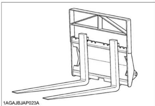
natural_image
Technical line drawing of a mechanical lifting frame assembly (no text or symbols)LOADER MODEL RATED CAPACITY
LA240A, LA240A AU-SG 310 LBS.
ASSEMBLE PALLET FORK
[Option for LA240A, LA240A AU-SG]
- Install the fork to the middle of the frame. (fit the lower hook of the fork to the center notch of the frame)
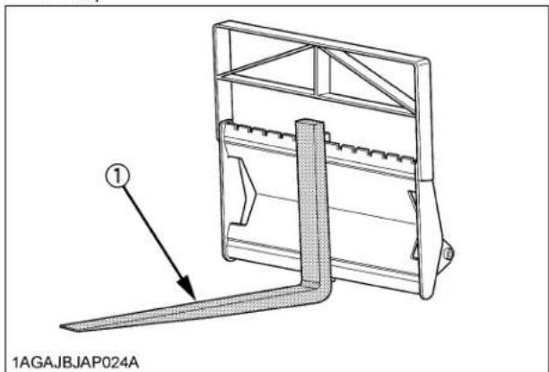
(1) Fork
- Slide the fork to the desired position.

(1) Fork
- Push the lock lever and slide the fork slightly until the lock pin engages with one of the notches to lock the folk.

(1) Lock lever
- The other fork can be installed using the same procedures.
![KUBOTA LA240A - [Option for LA240A, LA240A AU-SG] - 4](/content/2026/05/991150/images/75d24eb60c143ad4e0227b4ea2ec2a3fc1909ba047c245cb2a3b2a044c740ad0.jpg)
natural_image
Technical line drawing of a mechanical lifting frame assembly (no text or symbols)To avoid personal injury:
- Use care when operating on slopes to avoid tip over. Travel at speed compatible with safe operation, especially when operating in uneven terrain, crossing ditches or while turning.
- This backhoe can be operated at any engine speed from about 75% of rated rpm to factory rated rpm. The backhoe is most efficient at rated engine speed. However, in special digging condition, for optimal fuel economy, or in residential neighborhood where noise may be a consideration, the engine speed can be lowered to about 75% of rated rpm.
- When operating in temperature below 0 C (32 F), run the tractor engine below about 50% of rated rpm until the oil temperature exceeds 0°C (32 F).
BACKHOE CONTROLS

CAUTION
To avoid personal injury:
- For all excavation work, operate the backhoe from the backhoe operator's seat only.
- Do not tamper with any backhoe control valve relief pressure setting.
The relief valve is preset at the factory. Changing the setting can cause overloading of the backhoe and the tractor and serious personal injury may result.
The backhoe is controlled by using the 2 lever "joystick" system. The left lever controls the boom and swing circuits, and the right lever controls the dipperstick and bucket circuits. The further the levers are moved from "NEUTRAL", the faster the component will move. Learn the "feature" of the controls for smooth and precise component movement.
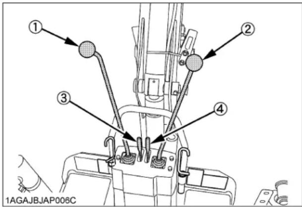
(1) Boom and swing lever
(2) Dipperstick and bucket lever
(3) Stabilizer control lever, left
(4) Stabilizer control lever, right
■Boom & Swing Lever
Pushing the lever forward will lower the boom, and pulling it back will raise it.
Movement of the lever to the left will swing the bucket to the left, and right lever movement will swing to the right.
By moving the lever out of the plus "+" position ; into an "X" relationship, it is possible to raise or lower and swing at the same time.
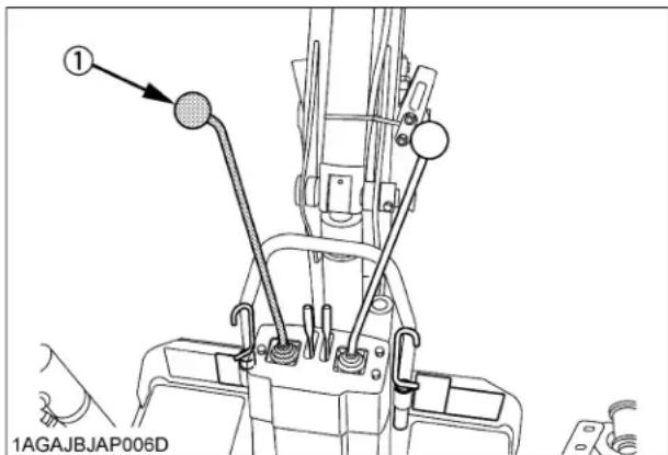
(1) Boom and swing lever
■Dipperstick & Bucket Lever
Pushing the lever forward will crowd out the dipperstick and the bucket out and pulling it back will crowd them in. Lever movement to the left will curl the bucket to fill it, and right lever movement will dump the bucket.
Again, movement into an "X" relationship will crowd in and fill the bucket, or crowd out and dump the bucket.
With experience, the combination of both "joystick" levers will allow lift, swing, crowd out and spoil dumping, all in one smooth movement, or lowering, swing, crowd in and bucket filling with reverse movement.

(1) Dipperstick and bucket lever
■Stabilizer Control Levers
The stabilizers are the only controls that may be operated from out of the backhoe operator's seat over then only for the purpose of mounting or dismounting backhoe from tractor.
Be sure to stay well clear of stabilizers, arms and pads during installation or removal process. This is necessary because the mounting step moves up and down in conjunction with the stabilizer cylinder.
Moving the levers downward will lower the stabilizers, and upward lever movement will raise them.
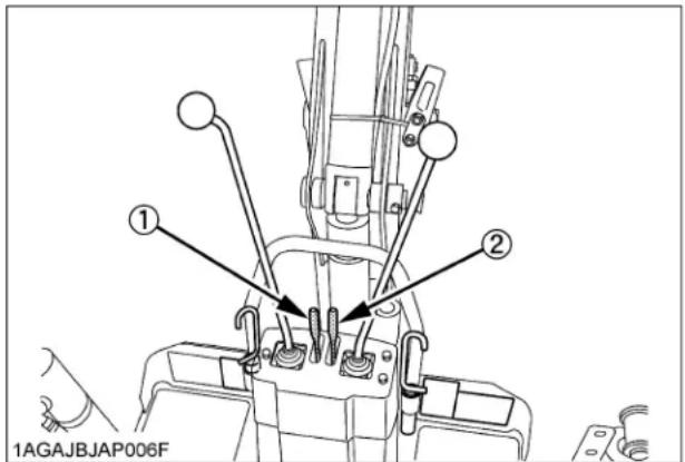
(1) Stabilizer control lever, left
(2) Stabilizer control lever, right
PLACING THE STABILIZERS

CAUTION
To avoid personal injury:
- When working on slopes, one stabilizer may be lower than the other.
-
When digging on a hillside, always dump the bucket on the uphill side of excavation.
● To reduce the risk of overturn on a slope, place the spoil to the high side of the excavation. -
Lower the stabilizers and remove the weight of the backhoe from the rear wheels. However, one or both rear tires should remain in light contact with the ground. This will give the backhoe the widest possible stance and the lowest center of gravity.
If the rear wheels are raised too high, digging depth will be reduced and undue stress will be exerted on the backhoe frame components.
If the slope is unusually steep, cut a level surface with the loader and pile the spoil on the downhill side. Back drag and pack the spoil so it will support the stabilizer on the low side. This procedure is recommended when a wall, tree line or other obstruction prevents placing backhoe spoil on the high side of the excavation.
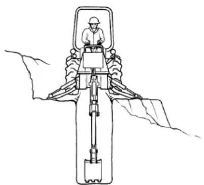
natural_image
Line drawing of a mechanical device with a worker operating it, surrounded by layered materials (no text or symbols)1HNAAAAAP096A
- The loader bucket should be lowered to give the backhoe unit a "tri-pod" stance. With the loader bucket in ground contact, front tire bounce will not be a factor in overall control. When possible, the loader bucket cutting edge should be lowered vertically into the ground surface. This will assist the stabilizers, not allowing the unit to shift, while excavating. However, on a slope, the bottom of the bucket should be used, and only the side that contacts the uneven terrain. Too much loader down pressure, on a slope, will restrict the unit from being correctly leveled and will place an undue twist through the loader bucket and lift arms.
To avoid personal injury:
- Do not dig under the stabilizer or tractor, especially in soft or sandy condition.
Take extra precaution in wet or thawing ground. These conditions can become unstable very quickly and may collapse under the weight of the machine and may tip over.
- Use care for buried material such as electrical, telephone, gas and water lines. When in doubt, contact local utility companies for their buried location.
IMPORTANT :
- Do not use the tractor to pull out tree stumps with the boom dipper extended and the bucket in its crowded position.

■Dipperstick Digging
Lower the bucket to the ground, the same as with bucket digging, then curl until the bucket teeth are flat on the ground.
Using only the crowd cylinder, retract the dipperstick, dragging the bucket through the trench until it is approximately half full. Begin to curl the bucket in while continuing to crowd in, until the bucket is completely full. Raise and swing the boom and dump the bucket in the spoil area on the high side of the trench or excavation.
■Spoil Pile Location

CAUTION
To avoid personal injury:
- Do not place spoil close to the edge of the excavation where its weight could cause a cave-in.
Carefully preplan the location for the spoil that will be removed from the excavation. The location will vary depending on the excavation being dug.
The height of spoil pile can be controlled without moving the tractor. Approach the pile with the backhoe bucket full and ready to empty. Instead of dumping on top, lower the full bucket into the top of the pile. Begin dumping and crowding out at the same time. As the bucket opens and dumps, the bottom of the bucket will push the top of the pile off and behind its location, safely away from the excavation.
■Straight Wall or Cemetery Digging
Strip the top soil off the ground, within the confines of the straight hole or grave to be dug. Clean out as much material, within the same confines, as possible with normal digging methods.
Finish the far wall by crowding out while forcing the bucket down with the boom.
Curl the bucket out to keep the bottom of the bucket vertical while making the down cut.
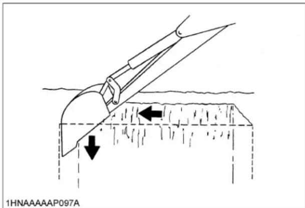
To finish the near wall, raise the boom while crowding in. The bucket will have to be curled in to keep the cutting edge horizontal with the wall during the up cut.

When finishing straight wall, or digging graves, in sandy soil, use a platform under the rear tires and stabilizers. The platform distributes the backhoe load over a large area and lessens the possibility of a cave-in.
■Stabilizer pads (Standard)

(1) Stabilizer pads
■Stabilizer pads (Option)
The stabilizer pads can be reversed without the use of tools. Change the pads depending on the job.

natural_image
Technical line drawing of a mechanical clamp or tool with directional arrows indicating motion (no text or symbols)◆When operating in dirt to prevent slippage.

natural_image
Technical line drawing of a mechanical clamp or lever assembly (no text or symbols)◆When operating on street to prevent damage to work area.
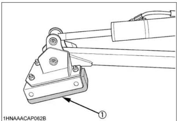
(1) Rubber shoes
IMPORTANT :
● Always lower stabilizers slightly when changing from one position to another to avoid soil splash.
TRANSPORTING

CAUTION
To avoid personal injury:
● Before transporting the machine, raise and center the boom, close the dipperstick, curl the bucket and engage the boom and swing locks.
● Always securely fasten the tractor / loader / backhoe, with chains and chain binders, to transport vehicle.
Determine and note the load height of the backhoe, for underpass clearance, before transporting.
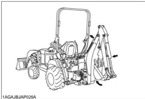
natural_image
Technical line drawing of a front-end loader with levers and stret, no text or symbols present■Driving to the Job-site
When driving or transporting from one job-site to another, or when using the loader such as stockpiling and backfilling, always engage the boom and swing locks.

(1) Boom lock pin
(2) Swing lock pin
■Trailer Transporting
When loading or off-loading the machine on or from trailer / truck, use strong, secure ramps long enough to provide a low angle to the transport vehicle.
After loading the machine, release the boom lock, lower the backhoe bucket to the bed of the transport vehicle, lower the loader bucket, set the parking brake of the tractor, shut the engine off and then remove the key.
Check the hood for proper securement, and remove SMV sign from holder driving transport to avoid damage, reinstall after transport.
Check the local codes or regulations that may apply to tractor / loader / backhoe operation on public streets or highways, before transporting or traveling. Use SMV emblem and warning flashers as required.
(SMV: Slow Moving Vehicle)
MAINTENANCE OF THE TRACTOR
SERVICE INTERVALS
| No. | Items | Indication on hour meter | Since then | Ref.page | ||||||||||||||||||
| 50 | 100 | 150 | 200 | 250 | 300 | 350 | 400 | 450 | 500 | 550 | 600 | 650 | 700 | |||||||||
| 1 | Engine oil Change every 200 Hr 89 | ○ | ○ | ○ | ||||||||||||||||||
| 2 | Engine oil filter Replace every 200 Hr 89 | ○ | ○ | ○ | ||||||||||||||||||
| 3 | Transmission oil filter | Replace every 200 Hr 90 | ○ | ○ | ○ | |||||||||||||||||
| 4 | Transmission fluid Change every 400 Hr 92 | ○ | ||||||||||||||||||||
| 5 | Transmission strainer | Clean every 400 Hr 93 | ○ | |||||||||||||||||||
| 6 | Front axle case oil Change every 400 Hr 94 | ○ | ||||||||||||||||||||
| 7 | Front axle pivot Adjust | ○ | every 400 Hr 92 | |||||||||||||||||||
| 8 | Engine start system | Check | ○ | ○ | ○ | ○ | ○ | ○ | ○ | ○ | ○ | ○ | ○ | ○ | ○ | ○ | ○ | ○ | every 50 Hr | 83 | ||
| 9 | OPC system | Check | ○ | ○ | ○ | ○ | ○ | ○ | ○ | ○ | ○ | ○ | ○ | ○ | ○ | ○ | ○ | ○ | every 50 Hr | 83 | ||
| 10 | Greasing | -- | ○ | ○ | ○ | ○ | ○ | ○ | ○ | ○ | ○ | ○ | ○ | ○ | ○ | ○ | ○ | ○ | every 50 Hr | 82 | ||
| 11 | Wheel bolt torque | Check | ○ | ○ | ○ | ○ | ○ | ○ | ○ | ○ | ○ | ○ | ○ | ○ | ○ | ○ | ○ | ○ | every 50 Hr | 84 | ||
| 12 | Battery condition | Check | ○ | ○ | ○ | ○ | ○ | ○ | every 100 Hr | 84 | *5 | |||||||||||
| 13 | Air cleaner element | Clean every 100 Hr 86 | *1 ○ | ○ | ○ | ○ | ○ | ○ | ||||||||||||||
| Replace every 1 year | 94 | *2 | ||||||||||||||||||||
| 14 | Fuel filter element | Check | ○ | ○ | ○ | ○ | ○ | ○ | ○ | every 100 Hr 86 | ||||||||||||
| Replace every 500 Hr 94 | *4 | ○ | ||||||||||||||||||||
| 15 | Fan belt | Adjust | ○ | ○ | ○ | ○ | ○ | ○ | ○ | every 100 Hr | 87 | |||||||||||
| 16 | HST neutral spring | Adjust | ○ | ○ | ○ | ○ | ○ | ○ | ○ | every 100 Hr | 87 | |||||||||||
| 17 | Brake pedal | Adjust | ○ | ○ | ○ | ○ | ○ | ○ | ○ | every 100 Hr 88 | ||||||||||||
| 18 | Radiator hose and clamp | Check | ○ | ○ | ○ | every 200 Hr 90 | ||||||||||||||||
| Replace every 2 years | 96 | |||||||||||||||||||||
| 19 | Power steering oil line | Check | ○ | ○ | ○ | every 200 Hr 92 | ||||||||||||||||
| Replace every 2 years | 96 | *4 | ||||||||||||||||||||
| 20 | Fuel line | Check | ○ | ○ | ○ | ○ | ○ | ○ | ○ | every 100 Hr 86 | ||||||||||||
| Replace every 2 years | 96 | *4 | ||||||||||||||||||||
| 21 | Intake air line | Check | ○ | ○ | ○ | every 200 Hr 91 | ||||||||||||||||
| Replace every 2 years | 96 | *4 | ||||||||||||||||||||
| 22 | Engine breather hose | Replace every 2 years | 96 | *4 | ||||||||||||||||||
| 23 | Toe-in | Adjust | ○ | ○ | ○ | every 200 Hr | 91 | |||||||||||||||
| 24 | Engine valve clearance | Adjust | every 800 Hr 94 | *4 | ||||||||||||||||||
| 25 | Fuel injection nozzle Injection pressure | Check | every 1500 Hr | 94 | *4 | |||||||||||||||||
| 26 | Injection pump | Check | every 3000 Hr | 94 | *4 | |||||||||||||||||
| 27 | Cooling system | Flush | every 2 years | 94 | ||||||||||||||||||
| 28 | Coolant | Change | every 2 years | 94 | ||||||||||||||||||
| 29 | Fuel system | Bleed | Service as required | 96 | ||||||||||||||||||
| 30 | Fuse | Replace | 97 | |||||||||||||||||||
| 31 | Light bulb | Replace | 97 | |||||||||||||||||||
IMPORTANT :
● The jobs indicated by must be done after the first 50 hours of operation.
*1 Air cleaner should be cleaned more often in dusty conditions than in normal conditions.
*2 Every year or every 6 times of cleaning.
*3 Replace only if necessary.
*4 Consult your local KUBOTA Dealer for this service.
*5 When the battery is used for less than 100 hours per year, check the battery condition by reading the indicator annually.
LUBRICANTS, FUEL AND COOLANT
| No. | Locations Capacities Lubricants | |||
| 1 Fuel 25 L | No. 2-D diesel fuelNo. 1-D diesel fuel if temperature is below-10°C | |||
| 2 | Coolant(with recovery tank) | 3.1 L | Fresh clean soft water with anti-freeze | |
| 3 Engine crankcase 3.1 L *1 | ●Engine oil: API Service Classification CF or better | |||
| Above 25°SAE30, SAE10W-30or 15W-40 | ||||
| 0 to 25°SAE20, SAE10W-30or 15W-40 | ||||
| Below 0°SAE10W, SAE10W-30or 15W-40 | ||||
| 4 Transmission case 11.6 L | KUBOTA SUPER UDT fluid *2 | ● | ||
| 5 Front axle case 4.7 L | ●KUBOTA SUPER UDT fluid *2 or SAE 80 -SAE90 gear oil | |||
| 6 | Greasing | No. of greasing points | Capacity | Type of grease |
| Battery terminal | 2 | moderate amount | Multipurpose EP2 Grease(NLGI Grade No. 2) | |
| Speed control pedal 1 | until grease overflow | |||
Note *1 Oil amount when the oil level is at the upper level of the oil level gauge.
*2 The product name of KUBOTA genuine UDT fluid may be different from that in the Operator's Manual depending on countries or territories. Consult your local KUBOTA Dealer for further detail.
IMPORTANT :
● To prevent serious damage to hydraulic systems, use only KUBOTA genuine fluid or its equivalent.
NOTE :
◆Engine Oil:
- Oil used in the engine should have an American Petroleum Institute (API) service classification and Proper SAE Engine Oil according to the ambient temperatures as shown above:
- With the emission control now in effect, the CF-4 and CG-4 lubricating oils have been developed for use of a low-sulfur fuel on on-road vehicle engines. When an off-road vehicle engine runs on a high-sulfur fuel, it is advisable to employ the "CF or better" lubricating oil with a high Total Base Number (TBN of 10 minimum).
- Refer to the following table for the suitable API classification engine oil according to the engine type (with internal EGR, external EGR or non-EGR) and the fuel (low-sulfur or high-sulfur fuel).
| Fuel used | Engine oil classification (API classification) | |
| Oil class of engines except external EGR Oil class of engines with external EGR | ||
| High Sulfur Fuel [0.05% (500 ppm)] | CF(If the "CF-4, CG-4, CH-4 or CI-4" lubricating oil is used with a high-sulfur fuel, change the lubricating oil at shorter intervals. (approximately half)) | --- |
| Low Sulfur Fuel [<0.05% (500 ppm)] or Ultra Low Sulfur Fuel [<0.0015% (15 ppm)] | CF, CF-4, CG-4, CH-4 or CI-4 | CF or CI-4(Class CF-4, CG-4 and CH-4 engine oils cannot be used on EGR type engines) |
EGR: Exhaust Gas Re-circulation
● The CJ-4 engine oil is intended for DPF (Diesel Particulate Filter) type engines, and cannot be used on this tractor.
| except external EGR with external EGR | ||
| Model BX25DLB-AU --- | ||
◆Fuel:
- Cetane number of 45 is minimum. Cetane number greater than 50 is preferred, especially for temperatures below -20 °C or elevations above 1500 m.
- If diesel fuel with sulfur content greater than 0.5% (5000 ppm) sulfur content is used, reduce the service interval for engine oil and filter by 50%.
- NEVER use diesel fuel with sulfur content greater than 0.05% (500 ppm) for EXTERNAL EGR type engine.
● DO NOT use diesel fuel with sulfur content greater than 1.0% (10000 ppm).
● Diesel fuels specified to EN 590 or ASTM D975 are recommended.
● No.2-D is a distillate fuel of lower volatility for engines in industrial and heavy mobile service. (SAE J313 JUN87)
◆Transmission Oil:
The oil used to lubricate the transmission is also used as hydraulic fluid. To insure proper operation of the hydraulic system and to complete lubrication of the transmission, it is important that a multi-grade transmission fluid is used in this system. We recommend the use of KUBOTA UDT or SUPER UDT fluid for optimum protection and performance. (Consult your local KUBOTA Dealer for further detail.)
Do not mix different brands together.
- Indicated capacities of water and oil are manufacturer's estimate.
PERIODIC SERVICE OF THE TRACTOR

CAUTION
To avoid personal injury:
- Do not work under any hydraulically supported devices. They can settle, suddenly leak down, or be accidentally lowered. If necessary to work under tractor or any machine elements for servicing or adjustment, securely support them with stands or suitable blocking beforehand.
HOW TO OPEN THE HOOD

CAUTION
To avoid personal injury from contact with moving parts;
● Never open the hood or engine side cover while the engine is running.
- Do not touch muffler or exhaust pipes while they are hot;
Severe burns could result.
Hood
To open the hood, rotate the knob to release the latch and open the hood.

(1) Knob
(2) Hood
(A) "ROTATE"
■Engine Cover
- Remove the front-end loader before removing the engine cover. (See "REMOVING THE LOADER" section.)
- To remove front guard, remove the bolts and the nuts.

(1) Bolts
(2) Nuts
(3) Front guard
(4) Tail pipe
- Loosen the screw bolt by using a long screwdriver and remove the tail pipe.
To remove the engine cover, loosen the knob bolts.

(1) Tail pipe
(2) Screw bolt

(1) Knob bolts
- Close the hood halfway and fix the band to the hood. Then, hold the hood with the band, and pull forward as shown in following figure. In the above procedure, be careful not to hit the engine cover against the head lights. It is not necessary to detach the engine cover for daily check.

(1) Band

(1) Engine cover (A) "PULL"
NOTE :
- When reinstall the engine cover, tighten the knob bolts.
- When reinstall the front guard, tighten the bolts and the nuts by 77.4 to 90.2 N-m (7.9 to 9.2 kgf-m)
DAILY CHECK
For your own safety and maximum service life of the machine, make a thorough daily inspection before operating the machine or starting the engine.

CAUTION
To avoid personal injury:
Take the following precautions when checking the tractor.
● Park the machine on firm and level ground.
- Set the parking brake.
● Lower the implement to the ground.
● All residual pressure of the hydraulic system released.
- Stop the engine and remove the key.
■Walk Around Inspection
Look around and under the tractor for such items as loose bolts, trash build-up, oil or coolant leaks, broken or worn parts.
■ Checking and Refueling

CAUTION
To avoid personal injury:
- Do not smoke while refueling. - Be sure to stop the engine and remove the key before refueling.
To avoid allergic skin reaction:
● Wash hands immediately after contact with diesel fuel.
- Turn the key switch to "ON", check the amount of fuel by fuel gauge.
- Fill fuel tank when fuel gauge shows 1/4 or less fuel in tank.
- Use grade No.2-Diesel fuel at temperatures above -10°C Use grade No.1-Diesel fuel at temperatures below -10°C
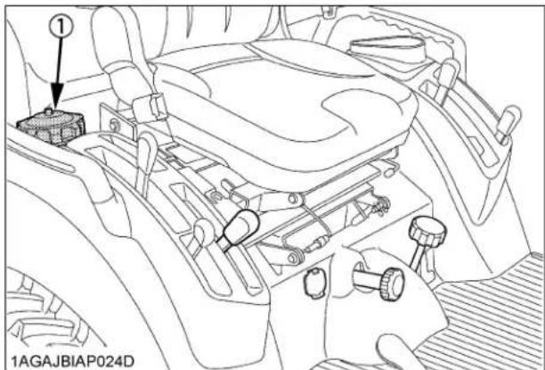
(1) Fuel tank cap
Fuel tank capacity 25 L
IMPORTANT :
- Do not permit dirt or trash or water to get into the fuel system.
- Be careful not to let the fuel tank become empty, otherwise air will enter the fuel system, necessitating bleeding before next engine start.
- Be careful not to spill fuel during refueling. If a spill should occur, wipe it off at once, or it may cause a fire.
● To prevent condensation (water accumulation) in the fuel tank, fill the tank before parking overnight.
■ Checking Engine Oil Level

CAUTION
To avoid personal injury:
- Be sure to stop the engine and remove the key before checking the oil level.
- Park the machine on a firm, flat and level surface.
- Check engine oil before starting the engine, or, after 5 minutes or more when the engine has been stopped.
- To check the oil level, draw out the dipstick, wipe it clean, replace it, and draw it out again. Check to see that the oil level lies between the two notches. If the level is too low, add new oil to the prescribed level at the oil inlet.
(See "LUBRICANTS" in "MAINTENANCE OF THE TRACTOR" section.)

(1) Oil inlet
(2) Dipstick
(A) Oil level is acceptable within this range.
IMPORTANT :
- When using an oil of different maker or viscosity from the previous one, remove all of the old oil and oil filter. Never mix two different types of oil.
- If oil level is low, do not run engine.
- When using BT602 Backhoe and checking oil level, locate the tractor/loader/backhoe on a flat and set the loader/backhoe as illustrated below.

natural_image
Line drawing of a mechanical front-end loader (no text or symbols on the vehicle itself)■ Checking Transmission Fluid Level
- Park the machine on a firm, flat and level surface, lower the implement to the ground and stop the engine.
- To check the oil level, draw out the dipstick, wipe it clean, replace it, and draw it out again. Check to see that the oil level lies between the two notches.
If the level is too low, add new oil to the prescribed level at the oil inlet.
(See "LUBRICANTS" in "MAINTENANCE OF THE TRACTOR" section.)

(1) Oil inlet
(A) Oil level is acceptable within this range.
(2) Dipstick
IMPORTANT :
- If oil level is low, do not run engine.
■ Checking Coolant Level

CAUTION
To avoid personal injury:
- Be sure to stop the engine and remove the key before checking coolant level.
-
Do not remove the radiator cap while coolant is hot. When cool, slowly rotate cap to the first stop and allow sufficient time for excess pressure to escape before removing cap completely.
-
Check to see that the coolant level is between the "H" and "L" marks of recovery tank.
- When the coolant level drops due to evaporation, add soft water only. In case of leakage, add antifreeze and soft water in the specified mixing ratio up to the "H" level.
(See "Flushing Cooling System and Changing Coolant" in "EVERY 2 YEARS" in "PERIODIC SERVICE OF THE TRACTOR" section.)

(1) Recovery tank (A) "H"
(B) "L"
IMPORTANT :
- If the radiator cap has to be removed, follow the above "CAUTION" and securely retighten the cap.
- Use clean, fresh soft water and anti-freeze to fill the recovery tank.
- If water should leak, consult your local KUBOTA Dealer.
■Cleaning Panel and Radiator Screen

CAUTION
To avoid personal injury:
- Be sure to stop the engine and remove the key before removing the screen.
● Before checking or cleaning it, wait long enough until it cools down.
- Check panel screen to be sure they are clean from debris.
- Detach the radiator screen, and then remove all the foreign material.
NOTE :
- If the dust or chaff is accumulated in the battery compartment, open the panel and clean completely.

(1) Panel
(A) "DETACH"
(2) Knob
(3) Center pillar

(1) Radiator screen (A) "DETACH"
IMPORTANT :
- Panel and radiator screen must be clean from debris to prevent engine from overheating and to allow good air intake for air cleaner.
- Be sure to reinstall the panel on the pillar completely to prevent the invasion of dust.
- Be sure to stop the engine to avoid personal injury and to allow good air intake for air cleaner.
■ Checking Brake Pedal
- Inspect the brake pedal for free travel, and smooth operation.
- Adjust if incorrect measurement is found: (See "Adjusting Brake Pedal" in "EVERY 100 HOURS" in "PERIODIC SERVICE OF THE TRACTOR" section.)
■ Checking Gauges, Meters and Easy Checker(TM)
- Inspect the instrument panel for broken gauge(s), meter(s) and Easy Checker(TM) lamps.
- Replace if broken.
■ Checking Head Light, Hazard Light etc.
- Inspect the lights for broken bulbs and lenses.
- Replace if broken.
■ Checking Seat Belt and ROPS
- Always check condition of seat belt and ROPS attaching hardware before operating tractor.
- Replace if damaged.
■ Checking and Cleaning of Electrical Wiring and Battery Cables

CAUTION
To avoid personal injury:
● A loosened terminal or connector, or damaged wire may affect the performance of electrical components or cause short circuits. Leakage of electricity could result in a fire hazard, a dead battery or damage to electrical components.
- Replace damaged wires or connections promptly.
- If a fuse blows soon after replacement, DO NOT USE A LARGER THAN RECOMMENDED FUSE OR BYPASS THE FUSE SYSTEM.
- Many wiring connections are protected by waterproof plugs, plug and unplug these connections carefully and make sure they are sealed correctly after assembly.
●Accumulation of dust, chaff or spilled fuel deposits around the battery, electrical wiring, engine or exhaust system are a fire hazard. CLEAN THESE AREAS BEFORE STARTING WORK.
To avoid premature electrical malfunctions DO NOT APPLY high pressure water directly to battery, wiring, connectors, electrical components or instrument panel.
Inspect the following Regularly:
- Check wiring for chafed or cracked insulation.
- Check wiring harness clamps. Replace if necessary.
-
Check connectors and terminals for looseness, contamination or overheated (discolored) connections.
-
Check instrument panel for correct operation of switches and gauges.
Consult your KUBOTA Dealer regarding maintenance, diagnosis and repair.
■ Checking Movable Parts
If any of the movable parts, such as levers and pedals, is not smoothly moved because of rust or anything sticky, do not attempt to force it into motion.
In the above case, remove the rust or the sticky thing, and apply oil or grease on the relevant spot.
Otherwise, the machine may get damaged.
EVERY 50 HOURS
■ Lubricating Grease Fittings
Apply a small amount of multipurpose grease to the following points every 50 hours: If you operated the machine in extremely wet and muddy conditions, lubricate grease fittings more often.

(1) Grease fitting (Speed control pedal)

(1) Battery terminals
■ Checking Engine Start System

CAUTION
To avoid personal injury:
- Do not allow anyone near the tractor while testing.
- If the tractor does not pass the test, do not operate the tractor.
◆Preparation before testing.
- Sit on operator's seat.
- Set the parking brake and stop the engine.
- Shift the range gear shift lever to "NEUTRAL" position.
- Check the speed control pedal "NEUTRAL" position.
- Shift the PTO clutch lever to "OFF" position.
◆Test 1: Switch for the speed control pedal
- Make sure that the range gear shift lever is set in "NEUTRAL" position.
- Depress the speed control pedal.
- Turn the key to "START" position.
- The engine must not crank.
- If it cranks, consult your local KUBOTA Dealer for this service.
◆Test 2: Switch for the PTO clutch lever
- Make sure that the range gear shift lever is set in "NEUTRAL" position.
- Make sure that the speed control pedal is set in "NEUTRAL" position.
- Shift the PTO clutch lever to "ON" position.
- Turn the key to "START" position.
- The engine must not crank.
- If it cranks, consult your local KUBOTA Dealer for this service.
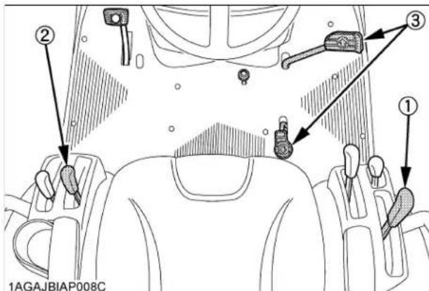
(1) Range gear shift lever (Hi-Lo)
(2) PTO clutch lever
(3) Speed control pedal
■ Checking OPC System

CAUTION
To avoid personal injury:
- Do not allow anyone near the tractor while testing.
- If the tractor does not pass the test, do not operate the tractor.
◆Preparation before testing.
- Sit on operator's seat.
- Set the parking brake and stop the engine.
- Shift the range gear shift lever to "NEUTRAL" position.
- Check the speed control pedal "NEUTRAL" position.
- Shift the PTO clutch lever to "OFF" position.
◆ Test 1: Switches for the operator's seat and the speed control pedal
- Start the engine.
- Depress the speed control pedal.
- Stand up. (Do not get off the machine.)
- The engine must shut off after approximately 1 second.
- If it does not stop, consult your local KUBOTA Dealer for this service.
◆ Test 2: Switches for the operator's seat and the PTO clutch lever.
- Start the engine.
- Engage the PTO clutch lever.
- Stand up. (Do not get off the machine.)
- The engine must shut off after approximately 1 second.
- If it does not stop, consult your local KUBOTA Dealer for this service.

(1) Range gear shift lever (Hi-Lo)
(2) PTO clutch lever
(3) Speed control pedal
■ Checking Wheel Bolt Torque

CAUTION
To avoid personal injury:
● Never operate tractor with a loose rim, wheel, or axle.
● Any time bolts are loosened, retighten to specified torque.
- Check all bolts frequently and keep them tight.
Check wheel bolts regularly especially when new. If they are loose, tighten them as follows.
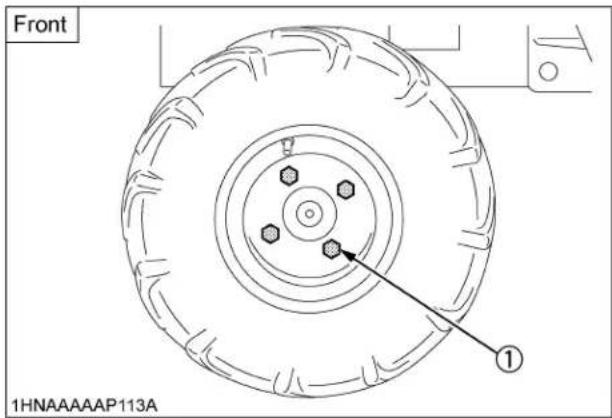
(1) 149.2 to 179.0 N-m (15.2 to 18.3 kgf-m)

(1) 108.5 to 130.2 N-m (11.1 to 13.3 kgf-m)
EVERY 100 HOURS
Battery

DANGER
To avoid the possibility of battery explosion: For the refillable type battery, follow the instructions below.
- Do not use or charge the refillable type battery if the fluid level is below the LOWER (lower limit level) mark. Otherwise, the battery component parts may prematurely deteriorate, which may shorten the battery's service life or cause an explosion. Check the fluid level regularly and add distilled water as required so that the fluid level is between the UPPER and LOWER levels.

CAUTION
To avoid personal injury:
● Never remove the battery cap while the engine is running.
- Keep electrolyte away from eyes, hands and clothes. If you are spattered with it, wash it away completely with water immediately and get medical attention.
- Keep open sparks and flames away from the battery at all times. Hydrogen gas mixed with oxygen becomes very explosive.
● Wear eye protection and rubber gloves when working around battery.
The factory-installed battery is of non-refillable type. If the battery is weak, charge the battery or replace it with new one.
IMPORTANT :
- Mishandling the battery shortens the service life and adds to maintenance costs.
The original battery is maintenance free, but needs some servicing.
If the battery is weak, the engine will be difficult to start and the lights will be dim. It is important to check the battery periodically.
- When exchanging an old battery for new one, use battery of equal specification in table below.
| Battery Type | Volts (V) | Reserve Capacity (min) | Cold Cranking Amps | Normal Charging Rate(A) |
| 526RMF 12 | 80 540 6.5 |
(For non-accessible maintenance-free type batteries.)
Maintenance-free, non-accessible batteries are designed to eliminate the need to add water. Yet the volume of electrolyte above plates may eventually become depleted due to abnormal conditions such as high heat or improper regulator setting. Use a voltmeter to check the state of charge. (See reference chart below to determine if charging is necessary.)
| Battery voltage Reference state of charge | |
| 12.6 | 100%(Full charge) |
| 12.4 75% | |
| 12.2 50% | |
| 12.0 25% | |
| 11.8 0% | |
◆Battery Charging

CAUTION
To avoid personal injury:
- When the battery is being activated, hydrogen and oxygen gases in the battery are extremely explosive. Keep open sparks and flames away from the battery at all times, especially when charging the battery.
- When disconnecting the cable from the battery, start with the negative terminal first. When connecting the cable to the battery, start with the positive terminal first.
● Never check battery charge by placing a metal object across the posts. Use a voltmeter or hydrometer.
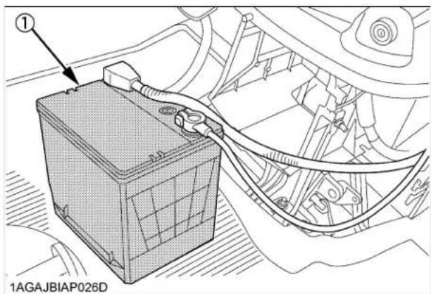
(1) Battery
- To slow charge the battery, connect the battery positive terminal to the charger positive terminal and the negative to the negative, then charge for at least 1 hour at 6.5 amperes.
- A boost charge is only for emergencies. It will partially charge the battery at a high rate and in a short time. When using a boost-charged battery, it is necessary to recharge the battery as early as possible. Failure to do this will shorten the battery's service life.
- When the specific gravity of electrolyte is between 1.27 and 1.29 the charging is completed.
◆Battery for storage
- When storing the tractor for a long period, remove the battery from tractor, adjust the electrolyte to the proper level and store in a dry place out of direct sunlight.
- The battery self-discharges while it is stored. Recharge it once every 3 months in hot seasons and once every 6 months in cold seasons.
■Cleaning Air Cleaner Element

CAUTION
To avoid personal injury:
- Be sure to stop the engine and remove the key before cleaning air cleaner element.
- Remove the air cleaner cover and the element.
(1) Undo the hook
(2) Turn the cover clockwise and detach it.
- Clean the element:
1) When dry dust adheres to the element, blow compressed air from the inside, turning the element. Pressure of compressed air must be under 205kPa (2.1kgf/cm²)
2) When carbon or oil adheres to the element, soak the element in detergent for 15 minutes then wash it several times in water, rinse with clean water and dry it naturally. After element is fully dried, inspect inside of the element with a light and check if it is damaged or not. (referring to the instructions on the label attached to the case.)
- Replace air cleaner element:
Once yearly or after every sixth cleaning, whichever comes first.
NOTE :
- Check to see if the evacuator valve is blocked with dust.

(1) Element
(2) Cover
(3) Evacuator valve
IMPORTANT :
● The air cleaner uses a dry element, never apply oil.
- Do not run the engine with filter element removed
- Align the arrow marks when reinstalling the cover. If the cover is improperly fitted, dust passes by the baffle and directly adheres to the element.
◆Evacuator Valve
Open the evacuator valve once a week under ordinary conditions - or daily when used in a dusty place - to get rid of large particles of dust and dirt.
■ Checking Fuel Lines and Fuel Filter

CAUTION
To avoid personal injury:
- Stop the engine and remove the key before checking fuel lines and fuel filter.
- Check the fuel lines periodically. The fuel lines are subject to wear and aging. Fuel may leak out onto the running engine, causing a fire.
The fuel line connections should be checked annually or every 100 service hours, whichever occurs first.
- The fuel line is made of rubber and ages regardless of service period.
- After inspection, if the fuel line and clamps are found damaged or deteriorated, replace them.
- Check fuel filter, if it is clogged by debris or contaminated by water, replace it.
IMPORTANT :
- When the fuel line is disconnected for maintenance or repair, plug both ends of the fuel line with a clean plug of suitable size to prevent dust and dirt from entering. Particular care must be taken in order to avoid dust and dirt getting into the fuel system. Entrance of dust and dirt causes malfunction of the fuel pump.
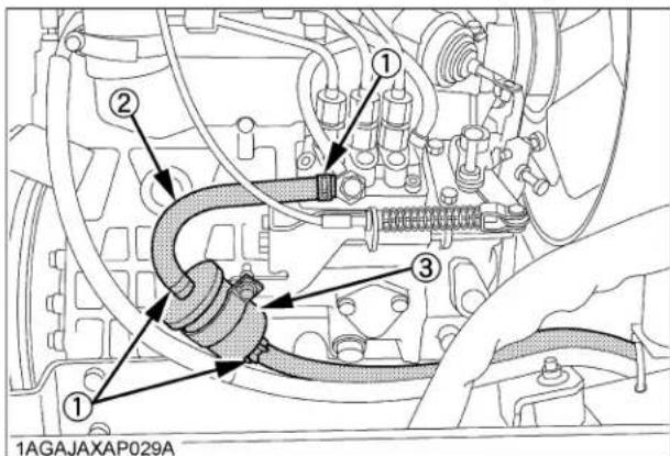
(1) Pipe clamps
(2) Fuel line
(3) Fuel filter

(1) Fuel pump
(2) Fuel filter
NOTE :
- If the fuel line is removed, be sure to properly bleed the fuel system.
(See "Bleeding Fuel System" in "SERVICE AS REQUIRED" in "PERIODIC SERVICE OF THE TRACTOR" section.)
■Adjusting Fan belt Tension

CAUTION
To avoid personal injury:
- Be sure to stop the engine and remove the key before checking belt tension.
| Proper fan belt tension | A deflection of between 7 to 9 mm when the belt is pressed in the middle of the span. |
- Stop the engine and remove the key.
- Apply moderate thumb pressure to belt between pulleys.
- If tension is incorrect, loosen the alternator mounting bolts and, using a lever placed between the alternator and the engine block, pull the alternator out until the deflection of the belt falls within acceptable limits.
- Replace fan belt if it is damaged.
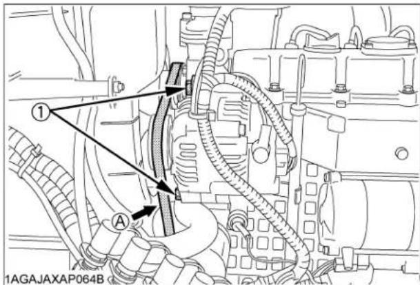
(1) Bolt (A) Check the belt tension
■Adjusting HST Neutral Spring (for Speed Control Pedal)

WARNING
To avoid personal injury:
- Do not operate if tractor moves on level ground with foot off speed control pedal.
- If tractor moves on level ground with foot off the pedal, or, if the pedal is too slow in returning to "NEUTRAL" position when removing the foot from the pedal, consult your local KUBOTA Dealer.
The HST neutral spring located under the front right side of the fender can adjust returning speed of speed control pedal. Consult your local KUBOTA Dealer for service.
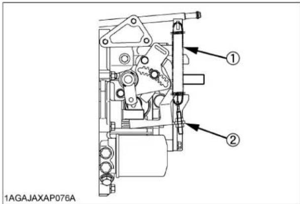
(1) HST neutral spring
(2) Adjusting nut
■Adjusting Brake Pedal

CAUTION
To avoid personal injury:
- Stop the engine, remove the key, lower the implement to the ground, and chock the wheels before checking brake pedal.
● Even if the brake pedal free travel is within the limitation, adjust the brake pedal following the procedure below. - If you are not able to adjust, consult your local KUBOTA Dealer.
| Proper brake pedal free travel | 25 to 35 mm on the pedal |
- Release the parking brake.
- Loosen the lock nut and turn the turnbuckle to adjust the rod length so that the brake pedal free travel is 10 mm.
- Extend the turnbuckle one additional turn.
- Retighten the lock nut.
- Depress the brake pedal several times and make sure the brake pedal free travel is from 25 to 35 mm.

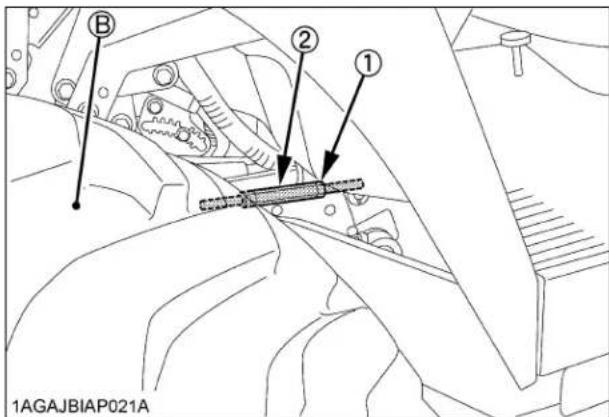
(1) Lock nut
(2) Turnbuckle
(A) Free travel
(B) Right rear tire
1AGAJBIAP020A
EVERY 200 HOURS
■Replacing Engine Oil Filter

CAUTION
To avoid personal injury:
- Be sure to stop the engine and remove the key before changing the oil filter cartridge.
-
Allow engine to cool down sufficiently, oil can be hot and can burn.
-
Remove the oil filter.
- Put a film of clean engine oil on the rubber seal of the new filter.
- Tighten the filter quickly until it contacts the mounting surface.
Tighten filter by hand an additional 1/2 turn only. - After the new filter has been replaced, the engine oil normally decreases a little. Make sure that the engine oil does not leak through the seal and be sure to check the oil level on the dipstick. Then, replenish the engine oil up to the prescribed level.
- Properly dispose of used oil.

(1) Engine oil filter
IMPORTANT :
● To prevent serious damage to the engine, use only a KUBOTA genuine filter.
■Changing Engine Oil

CAUTION
To avoid personal injury:
- Be sure to stop the engine and remove the key before changing the oil.
-
Allow engine to cool down sufficiently, oil can be hot and can burn.
-
To drain the used oil, remove the drain plug at the bottom of the engine and drain the oil completely into the oil pan.
All the used oil can be drained out easily when the engine is still warm. - After draining reinstall the drain plug.
- Fill with the new oil up to the upper notch on the dipstick.
(See "LUBRICANTS" in "MAINTENANCE OF THE TRACTOR" section.) - Properly dispose of used oil.
| Oil capacity with filter 3.1 L |

(1) Oil inlet
(2) Dipstick
(A) Oil level is acceptable within this range
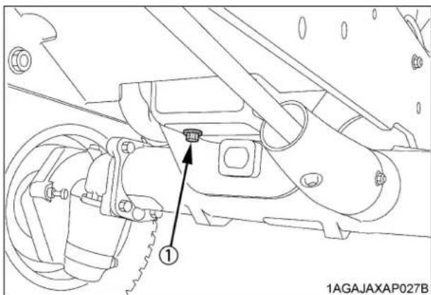
(1) Drain plug
■Replacing Transmission Oil Filter

CAUTION
To avoid personal injury:
- Be sure to stop the engine before changing the oil filter cartridge.
-
Allow engine to cool down sufficiently, oil can be hot and can burn.
-
Remove the oil filter.
- Put a film of clean transmission oil on rubber seal of new filter.
- Tighten the filter quickly until it contacts the mounting surface.
Tighten filter by hand an additional 1/2 turn only.
- After the new filter has been replaced, the transmission fluid level will decrease a little. Make sure that the transmission fluid does not leak through the seal, and check the fluid level.
Top up if necessary.
- Properly dispose of used oil.

(1) Filter
IMPORTANT :
● To prevent serious damage to the hydraulic system, use only a KUBOTA genuine filter.
■Checking Radiator Hoses and Clamps

CAUTION
To avoid personal injury:
- Be sure to stop the engine and remove the key before checking radiator hose and clamp.
Check to see if radiator hoses are properly secured every 200 hours of operation or 6 months, whichever comes first.
- If hose clamps are loose or water leaks, tighten bands securely.
- Replace hoses and tighten hose clamps securely, if radiator hoses are swollen, hardened or cracked.
- Properly dispose of used coolant. Replace hoses and hose clamps every 2 years or earlier if checked and found that hoses are swollen, hardened or cracked.
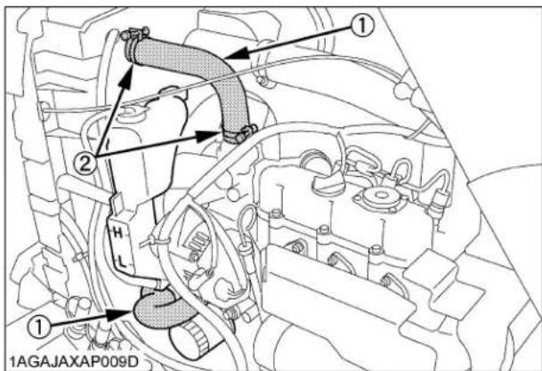
(1) Radiator hoses (2 pcs)
(2) Hose clamps (4 pcs)
◆Precaution at Overheating
Take the following actions in the event the coolant temperature be nearly or more than the boiling point, what is called "Overheating".
- Stop the machine operation in a safe place and keep the engine idling unloaded.
- Don't stop the engine suddenly, but stop it after about 5 minutes of unloaded idling.
- Keep yourself well away from the machine for an additional 10 minutes or until the steam has blown out.
- Checking that there is no danger such as burn, get rid of the causes of overheating according to the manual, see "TROUBLESHOOTING" section, and then, start the engine again.
■ Checking Intake Air Line

CAUTION
To avoid personal injury:
- Be sure to stop the engine and remove the key before checking intake air line.
- Check to see that hose and hose clamps are tight and not damaged.
- If hose and clamps are found to be worn or damaged, replace or repair them at once.
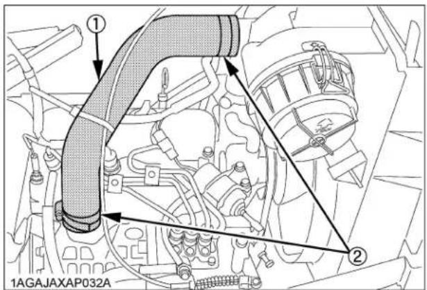
(1) Hose
(2) Hose clamp
■Adjusting Toe-in
- Park tractor on a firm, flat and level place.
- Turn steering wheel so front wheels are in the straight ahead position.
- Lower the implement to the ground, lock the parking brake, stop the engine and remove the key.
- Measure distance between tire beads at front of tire, hub height.
- Measure distance between tire beads at rear of tire, hub height.
- Front distance should be 0 to 5 mm less than rear distance. If not, adjust tie rod length.
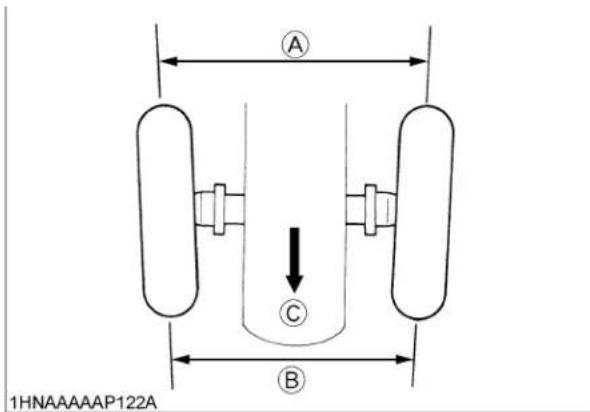
(A) Wheel - to - wheel distance at rear
(B) Wheel - to - wheel distance at front
(C) "FRONT"
◆Adjusting procedure
- Loosen the lock nut and turn the tie rod to adjust the rod length until the proper toe-in measurement is obtained.
- Retighten the lock nut.
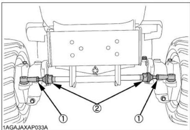
(1) Lock nuts
(2) Tie rod
■ Checking Power Steering Line

CAUTION
To avoid personal injury:
- Be sure to stop the engine and remove the key before checking power steering line.
- Check to see that all lines are tight and not damaged.
- If hoses are found to be worn or damaged, replace or repair them at once.

(1) Power steering pressure hose
EVERY 400 HOURS
■Adjusting Front Axle Pivot
If the front axle pivot pin adjustment is not correct, front wheel vibration can occur causing vibration in the steering wheel.
◆Adjusting procedure
Remove the split pin, tighten the adjusting nut (tightening torque 20 N-m, 2.0 kgf-m), then make sure that one of the nut slots aligns with the split pin hole, tighten the nut slightly if necessary to align. Replace the split pin.
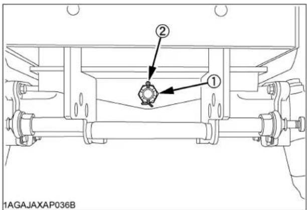
(1) Adjusting nut
(2) Split pin
■Changing Transmission Fluid

CAUTION
To avoid personal injury:
- Allow engine to cool down sufficiently, oil can be hot and can burn.
- To drain the used oil, remove the drain plug at the bottom of the transmission case and drain the oil completely into the oil pan.
- After draining reinstall the drain plug.
- Clean the transmission strainer.
- Fill with new KUBOTA SUPER UDT fluid up to the upper notch on the dipstick.
(See "LUBRICANTS" in "MAINTENANCE OF THE TRACTOR" section and "DAILY CHECK" in "PERIODIC SERVICE OF THE TRACTOR" section.) - After running the engine for a few minutes, stop it and check the oil level again, add oil to prescribed level.
- Properly dispose of used oil.
Oil capacity 11.6 L
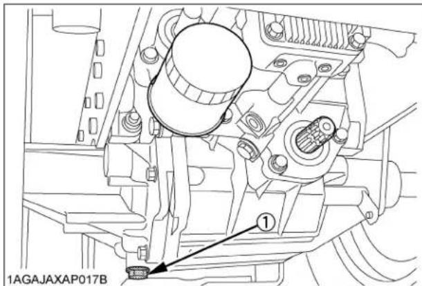
(1) Drain plug
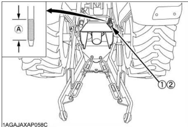
(1) Oil inlet
(A) Oil level is acceptable within this range.
(2) Dipstick
IMPORTANT :
- Do not operate the tractor immediately after changing the transmission fluid. Run the engine at medium speed for a few minutes to prevent damage to the transmission.
■Cleaning Transmission Strainer
When changing the transmission fluid, disassemble and rinse the strainer with nonflammable solvent to completely clean off filings.
When reassembling be careful not to damage the parts.
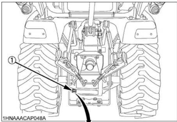

(1) Strainer
(2) Filter plate
NOTE :
- Since the fine filings in the oil can damage the precision component parts of the hydraulic system, the end of the suction line is provided with an oil strainer.
■Changing Front Axle Case Oil
- Park the machine on a firm, flat and level surface.
- To drain the used oil, remove the right and left drain plugs and oil gauge at the front axle case and drain the oil completely into the oil pan.
- After draining reinstall the drain plugs.
- Remove the right and left breather plugs.
- Fill with new oil up to the upper notch on the dipstick. (See "LUBRICANTS" in "MAINTENANCE OF THE TRACTOR" section.)
IMPORTANT :
● After 10 minutes, check the oil level again; add oil to prescribed level.
6. After filling, reinstall the oil gauge and breather plugs.
Oil capacity 4.7 L

(1) Breather plug
(2) Oil gauge with dipstick
(3) Drain plug
(A) Oil level is acceptable within this range
EVERY 500 HOURS
■Replacing Fuel Filter Element
Consult your local KUBOTA Dealer for this service.
EVERY 800 HOURS
■Adjusting Engine Valve Clearance
Consult your local KUBOTA Dealer for this service.
EVERY 1500 HOURS
■ Checking Fuel Injection Nozzle Injection Pressure
Consult your local KUBOTA Dealer for this service.
EVERY 3000 HOURS
■ Checking Injection Pump
Consult your local KUBOTA Dealer for this service.
EVERY 1 YEAR
■Replacing Air Cleaner Element
(See "Cleaning Air Cleaner Element" in "EVERY 100 HOURS" in "PERIODIC SERVICE OF THE TRACTOR" section.)
EVERY 2 YEARS
■Flushing Cooling System and Changing Coolant

CAUTION
To avoid personal injury:
- Do not remove the radiator cap while coolant is hot. When cool, slowly rotate cap to the first stop and allow sufficient time for excess pressure to escape before removing cap completely.
- Stop the engine and let cool down.
- To drain the coolant, open the radiator drain plug and remove radiator cap. The radiator cap must be removed to completely drain the coolant.
- After all coolant is drained, close the drain plug.
- Fill with clean soft water and cooling system cleaner.
- Follow directions of the cleaner instruction.
- After flushing, fill with clean soft water and anti-freeze until the coolant level is just below the radiator cap. Install the radiator cap securely.
- Fill with coolant up to the "H" mark on the recovery tank.
- Start and operate the engine for few minutes.
- Stop the engine and let cool.
- Check coolant level of recovery tank and add coolant if necessary.
| Coolant capacity(With recovery tank) | 3.1 L |

(1) Radiator cap

(1) Drain plug
IMPORTANT :
- Do not start engine without coolant.
- Use clean, fresh soft water and anti-freeze to fill the radiator and recovery tank.
- When mixing the anti-freeze with water, the anti-freeze mixing ratio is 50 %.
- Securely tighten radiator cap. If the cap is loose or improperly fitted, water may leak out and the engine could overheat.
Anti-Freeze

CAUTION
To avoid personal injury:
- When using anti-freeze, put on some protection such as rubber gloves. (Anti-freeze contains poison.)
- If it is swallowed, seek immediate medical help. Do NOT make a person throw up unless told to do so by poison control or a health care professional. Use standard first aid and CPR for signs of shock or cardiac arrest. Call your local Poison Control Center or your local emergency number for further assistance.
- When anti-freeze comes in contact with the skin or clothing, wash it off immediately.
- Do not mix different types of Anti-freeze. The mixture can produce chemical reaction causing harmful substances.
● Anti-freeze is extremely flammable and explosive under certain conditions. Keep fire and children away from anti-freeze. - When draining fluids from the engine, place some container underneath the engine body.
- Do not pour waste onto the grounds, down a drain, or into any water source.
- Also, observe the relevant environmental protection regulations when disposing of anti-freeze.
Always use a 50/50 mix of long-life coolant and clean soft water in KUBOTA engines.
Consult your local KUBOTA dealer concerning coolant for extreme conditions.
- Long-life coolant (hereafter LLC) comes in several types. Use ethylene glycol (EG) type for this engine.
- Before employing LLC-mixed cooling water, fill the radiator with fresh water and empty it again.
Repeat this procedure 2 or 3 times to clean up the inside.
-
Mixing the LLC Premix 50% LLC with 50% clean soft water. When mixing, stir it up well, and then fill into the radiator.
-
The procedure for the mixing of water and anti-freeze differs according to the make of the anti-freeze and the ambient temperature. Refer to SAE J1034 standard, more specifically also to SAE J814c.
IMPORTANT :
- When mixing the anti-freeze with water, the anti-freeze mixing ratio is 50%.
| Vol % Anti-freeze | Freezing Point Boiling Point* °C | °C |
| 50 -37 108 |
* At 1.013 x 10 5 Pa (760 mmHg) pressure (atmospheric).
A higher boiling point is obtained by using a radiator pressure cap which permits the development of pressure within the cooling system.
- Adding the LLC
(1) Add only water if the coolant level reduces in the cooling system by evaporation.
(2) If there is a mixture leak, add the LLC of the same manufacturer and type in the mixing ratio 50%.
* Never add any long-life coolant of different manufacturer. (Different brands may have different additive components, and the engine may fail to perform as specified.)
-
When the LLC is mixed, do not employ any radiator cleaning agent. The LLC contains anti-corrosive agent. If mixed with the cleaning agent, sludge may build up, adversely affecting the engine parts.
-
Kubota's genuine long-life coolant has a service life of 2 years. Be sure to change the coolant every 2 years.
NOTE :
● The above data represent industry standards that necessitate a minimum glycol content in the concentrated anti-freeze.
■Replacing Radiator Hose (Water pipes)
Replace the hoses and clamps.
(See "Checking Radiator Hoses and Clamps" in "EVERY 200 HOURS" in "PERIODIC SERVICE OF THE TRACTOR" section.)
■Replacing Power Steering Hose
Consult your local KUBOTA Dealer for this service.
■Replacing Fuel Lines
Consult your local KUBOTA Dealer for this service.
■Replacing Engine Breather Hose
Consult your local KUBOTA Dealer for this service.
■Replacing Intake Air Line
Consult your local KUBOTA Dealer for this service.
SERVICE AS REQUIRED
■Bleeding Fuel System
Air must be removed:
- When the fuel filter or lines are removed.
- When the tank is completely empty.
- After the tractor has not been used for a long period of time.
◆Bleeding procedure is as follows:
- Fill the fuel tank with fuel.

(1) Fuel pump
(2) Fuel filter
-
Turn the key switch to "ON" position for about 30 seconds. Doing so allows fuel pump to work and pump air out of the fuel system.
-
Start the engine and run for about 30 seconds, and then stop the engine.
■Replacing Fuse
The tractor electrical system is protected from potential damage by fuses.
A blown fuse indicates that there is an overload or short somewhere in the electrical system.
If any of the fuses should blow, replace with a new one of the same capacity.
IMPORTANT :
- Before replacing a blown fuse, determine why the fuse blew and make any necessary repairs. Failure to follow this procedure may result in serious damage to the tractor electrical system. Refer to the troubleshooting section of this manual or your local KUBOTA Dealer for specific information dealing with electrical problems.

(1) Fuse box

(1) Slow blow fuse
◆Protected circuit
[Fuse box]
| FUSE No. | CAPACITY (A) | Protected circuit |
| (1) 15 | SOLENOID | |
| (2) 15 | HAZARD | |
| (3) 15 | ACC | |
| (4) 20 | WORKING LIGHT | |
| (5) 10 | DC OUTLET | |
| (6) 10 | TIMER RELAY |
| CAPACITY (A) Protected circuit | |
| Slow blow Fuse (50A) | Check circuit against wrong battery connection |
■Replacing Light Bulb
- Head light
Take the bulb out of the light body and replace with a new one.
- Other lights
Detach the lens and replace the bulb.
| Light Capacity | |
| Head light 37.5W | |
| Tail light 12.8W | |
| Hazard light 23W |
MAINTENANCE OF THE LOADER

CAUTION
To avoid personal injury:
- Be sure to check and service the tractor on a flat surface with the bucket on the ground, engine shut off, the key removed and the parking brake on.
LUBRICATION
- Lubricate all grease fittings every 10 hours of operation. Also, lubricate joints of control lever linkage every 10 hours. High quality grease designating "extreme pressure" and containing Molybdenum disulfide is recommended. This grease may specify "Moly EP" on its label.
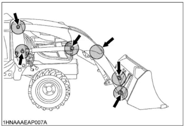
- Daily before operation, check the tractor hydraulic fluid level. If low, add as described in "PERIODIC SERVICE OF THE TRACTOR" section. Also change the filter element and the hydraulic fluid as recommended in "PERIODIC SERVICE OF THE TRACTOR" section.
RE-TIGHTENING OF HARDWARE
After 20 to 30 hours of initial loader operation, re-tighten all mounting bolts and nuts to the required torque value as specified in the "Tightening Torque Chart".
■Tightening Bolts and Nuts
Tighten all bolts and nuts with required torque.
| Location Bolt / Nut Required Torque | ||
| Main frame | M14bolts or nuts | 147 N-m(15.0 kgf-m) |
NOTE :
- Before finally tightening all mounting hardware, start the engine and apply down pressure to the bucket until the loader raises the front wheels slightly, and make sure that the mounting pins can be rotated easily. Tighten all bolts and nuts in this position.
DAILY CHECKS
- Check all hardware daily before operation.
Tighten hardware to torque values as specified in the "Tightening Torque Chart".
- With the engine off and the bucket on the ground, inspect all hoses for cuts or wear. Check for signs of leaks and make sure all fittings are tight.

CAUTION
To avoid serious personal injury:
- Escaping hydraulic fluid under pressure can have sufficient force to penetrate skin, causing serious personal injury. Before disconnecting lines, be sure to relieve all pressure.
Before applying pressure to system, be sure all connections are tight and that lines, tubes, and hoses are not damaged.
Fluid escaping from a very small hole can be almost invisible. Use a piece of cardboard or wood, rather than hands, to search for suspected leaks.

(1) Hydraulic line
(2) Cardboard
(3) Magnifying glass
If injured by escaping fluid, see a doctor at once. Serious infection or allergic reaction will develop if proper medical treatment is not administered immediately.
- When removing the engine side covers, be careful not to touch hot loader cylinders.
Allow all surfaces to cool before performing maintenance.
EVERY 50 HOURS
■ Checking main frame bolt and nut torque

CAUTION
To avoid personal injury:
● Never operate front loader with a loose main frame.
● Any time bolts and nuts are loosened, retighten to specified torque.
- Check all bolts and nuts frequently and keep them tight.
Check main frame bolts and nuts regularly especially when new. If they are loose, tighten them as follows.

(1) Tightening torque: 147 N-m (15.0 kgf-m)
MAINTENANCE OF THE BACKHOE
DAILY CHECKS

CAUTION
To avoid personal injury:
● Never make any repairs, service or adjustments when the hydraulic system is under pressure, when the engine is running or when any backhoe cylinder is under load.
● Escaping hydraulic fluid under pressure can have sufficient force to penetrate skin, causing serious personal injury. Before disconnecting lines, be sure to relieve all pressure. Before applying pressure to system, be sure all connections are tight and that lines, pipes and hoses are not damaged.
Fluid escaping from a very small hole can be almost invisible. Do not use hands to search for suspected leak, use a piece of cardboard or wood. If injured by escaping fluid, see a doctor at once. Serious infection or allergic reaction will develop if proper medical treatment is not administered immediately.

(1) Hydraulic line
(2) Cardboard
(3) Magnifying glass
- The backhoe is run by the tractor hydraulic system. Daily before operation, check the tractor hydraulic level. If low, replenish the oil as described in "PERIODIC SERVICE OF THE TRACTOR" section. Also check the filter screen and change the hydraulic fluid as recommended in "PERIODIC SERVICE OF THE TRACTOR" section.
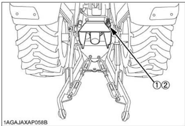
(1) Oil port
(2) Dipstick
- Check all hardware before daily operation. Tighten hardware to torque values as specified in the "General torque specification".
- With the engine off and the bucket on the ground, inspect all hoses for cuts or wear. Check for signs of leaks and make sure all fittings are tight.
- For safe operation, check that the mounting pin slide bar is inserted into the hole of the main frame before operation.

(1) Mounting pin
(2) Slide bar
LUBRICATION
Lubricate all grease fittings every 10 hours of operation. High quality grease designated "extreme pressure" and containing Molybdenum disulfide is recommended. This grease may specify "Moly Ep" on its label.

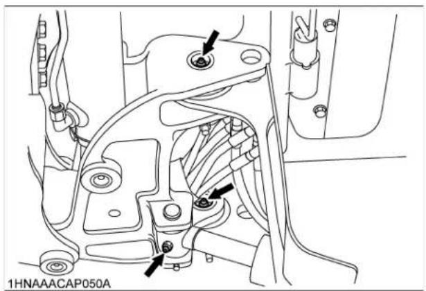

natural_image
Technical line drawing of a vehicle's internal components and suspension system (no text or symbols)BUCKET SERVICE

CAUTION
To avoid personal injury:
- When servicing or repairing pins in cylinder ends, bucket, etc., always use a brass drift and hammer. Failure to do so could result in injury from flying metal fragments.
■Changing the Backhoe Bucket
Changing the backhoe bucket becomes necessary as the type of job to be accomplished changes. In most backhoe operations, this is a common occurrence.
By using the following instructions, this job will be quick and easy. Always select a smooth level area to change buckets.
Place the bucket to be installed on its bottom, near the backhoe dipperstick and the bucket to be removed.
Position the bucket to be removed, hydraulically, into this "NATURAL" position, just touching the ground.
■Changing the Bucket Teeth
The bucket teeth are locked with bolts on the bucket. Even though the teeth are heat-treated and hard, they will eventually need replacement. As the teeth become worn, the resistance of digging will increase. When the teeth are worn, install new teeth using new bolts.
Bucket teeth may be removed and stored when drainage work is required. This type of work may not require trenching teeth.

(1) Bucket
(2) Bucket teeth
(3) Bolt
■General torque specification
| American standard cap screws with UNC or UNF threads | Metric cap screws | |||
| SAE grade No. GR5 or GR8 Property class | 8.8Approx. SAE GR5 | |||
| 1/4 | (N-m)(kgf-m) | 9.8 to 11.71.0 to 1.2 | M6 | (N-m)(kgf-m) |
| 5/16 | (N-m)(kgf-m) | 19 to 23.11.9 to 2.4 | M8 | (N-m)(kgf-m) |
| 3/8 | (N-m)(kgf-m) | 33.9 to 40.73.5 to 4.2 | M10 | (N-m)(kgf-m) |
| 1/2 | (N-m)(kgf-m) | 88.1 to 105.89.0 to 10.8 | M12 | (N-m)(kgf-m) |
| 9/16 | (N-m)(kgf-m) | 122 to 146.412.4 to 14.9 | M14 | (N-m)(kgf-m) |
| 5/8 | (N-m)(kgf-m) | 176.3 to 211.518.0 to 21.6 | M16 | (N-m)(kgf-m) |
Top of bolt

M8

M10

M12

M14

M16
1HNAAAAAP1310
Length

1HNAAAAAP1320
STORAGE OF THE TRACTOR

CAUTION
To avoid personal injury:
- Do not clean the machine while the engine is running.
● To avoid the danger of exhaust fume poisoning, do not operate the engine in a closed building without proper ventilation. - When storing, remove the key from the key switch to avoid unauthorized persons from operating the tractor and getting injured.
TRACTOR STORAGE
If you intend to store your tractor for an extended period of time, follow the procedures outlined below. These procedures will insure that the tractor is ready to operate with minimum preparation when it is removed from storage.
- Check the bolts and nuts for looseness, and tighten if necessary.
- Apply grease to tractor areas where bare metal will rust also to pivot areas.
- Detach the weights from the tractor body.
- Inflate the tires to a pressure a little higher than usual.
- Change the engine oil and run the engine to circulate oil throughout the engine block and internal moving parts for about 5 minutes.
- With all implements lowered to the ground, coat any exposed hydraulic cylinder piston rods with grease.
- Remove the battery from the tractor. Store the battery following the battery storage procedures. (See "Battery" in "EVERY 100 HOURS" in "PERIODIC SERVICE OF THE TRACTOR" section.)
- Keep the tractor in a dry place where the tractor is sheltered from the elements. Cover the tractor.
- Store the tractor indoors in a dry area that is protected from sunlight and excessive heat. If the tractor must be stored outdoors, cover it with a waterproof tarpaulin. Jack the tractor up and place blocks under the front and rear axles so that all 4 tires are off the ground. Keep the tires out of direct sunlight and extreme heat.
IMPORTANT :
- When washing the tractor, be sure to stop the engine. Allow sufficient time for the engine to cool before washing.
- Cover the tractor after the muffler and the engine have cooled down.
REMOVING THE TRACTOR FROM STORAGE
- Check the tire air pressure and inflate the tires if they are low.
- Jack the tractor up and remove the support blocks from under the front and rear axles.
- Install the battery. Before installing the battery, be sure it is fully charged.
- Check the fan belt tension.
- Check all fluid levels (engine oil, transmission/hydraulic oil, engine coolant and any attached implements).
- Start the engine. Observe all gauges. If all gauges are functioning properly and reading normal, move the tractor outside. Once outside, park the tractor and let the engine idle for at least 5 minutes. Shut the engine off and walk around tractor and make a visual inspection looking for evidence of oil or water leaks.
- With the engine fully warmed up, release the parking brake and test the brakes for proper adjustment as you move forward. Adjust the brakes as necessary.
REMOVING THE LOADER

CAUTION
To avoid personal injury:
● Make sure an approved bucket is attached before removing the loader from the tractor.
- For removing the loader, choose flat and hard ground, preferably concrete.
- If the ground surface is soft, place suitable planks on the ground for the bucket and stand.
- When starting the engine or using the loader control lever, always sit in the operator's seat.
● Make sure the bucket and stand are at ground level.
- Raise the boom until the stand can be rotated.
- Stop the engine.
- Remove the spring pin holding the stand to the boom.
- Slide the stand leftward and rotate it until the hole in the stand and pin on the boom are aligned.
Then slide the stand rightward and insert the spring pin as shown.
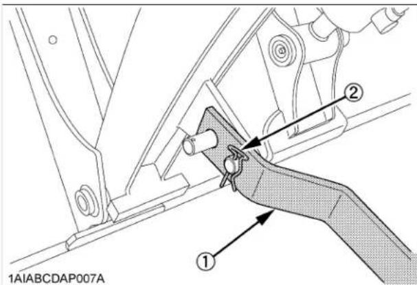
(1) Stand
(2) Spring pin
- Start the engine and run at idle.
- Dump the bucket approximately 20 degrees.
- Lower the boom and raise the front wheels slightly.

(1) Stand
IMPORTANT :
- Lift the front wheels with the bucket. Do not attempt to lift them with the stand.
- Stop the engine.
- Remove the mounting pins from the loader side frame and retain them in the plate of side frame.

(1) Mounting pin
- Start the engine and run at idle. Slowly move the loader control lever to rollback position to raise the loader side frames up and out of the receivers of the main frames as shown.

(1) Loader control lever
- Stop the engine.
- Slowly release all hydraulic pressure by moving the loader control lever in all directions.
- Disconnect the 4 hoses with quick couplers at the control valve and place them on the right side of the boom.
- Place the protective caps and plugs on the quick coupler ends.
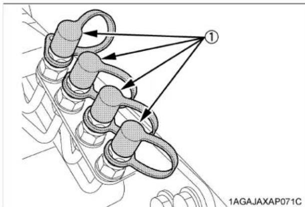
(1) Protective plug
- Start the engine and slowly back the tractor away from the loader.
STORAGE OF THE LOADER
- Store the loader in a clean dry place.
- Make sure the loader is properly supported.
- Attach the protective plugs and caps to the couplers to protect from dust.

natural_image
Technical line drawing of a mechanical excavator assembly (no text or symbols)- Check hydraulic hoses and connections. Repair or replace if necessary.
- Repair or replace any worm, damaged or missing parts.
- Lubricate loader as described "LUBRICATION" in "MAINTENANCE OF THE LOADER" section.
- Apply a coat of grease to all exposed cylinder rods and mounting pins to prevent rust.
- Repaint worn or scratched parts.
REINSTALLING THE LOADER

CAUTION
To avoid personal injury:
- When starting the engine and operating the control lever, always sit in the operator's seat.
- Slowly drive the tractor between the loader side frames until the rear portion of both side frames touches the main frames as shown.

(1) Side frame
(2) Main frame
- Stop the engine.
- Connect 4 hoses with couplers to the nipples on the control valve as indicated with color marks. Then connect the protective caps and plugs to each other.

(1) Hoses
[Spill guard model only]
IMPORTANT :
● The hydraulic hoses and the spill guard hoses are routed as shown below.


(1) Hydraulic hoses with couplers
(2) Spill guard hoses
(3) Hydraulic hose with coupler (White)
- Start the engine and run at idle.
- Slowly move the loader control lever to dump position to lower the side frames into the main frames and engage the bosses of the main frames to the guide bosses of the side frames. Then lift the front wheels slightly with the loader.

(1) Loader control lever
IMPORTANT :
- Do not attempt to lift the front wheels with the stand.
- Stop the engine. Reinstall the mounting pins and secure them with the locking rods.

(1) Mounting pin
- Start the engine.
- Raise the boom until the stand can be rotated.
- Stop the engine.
- Store the stand to their original positions and secure it with the spring pin as shown.

(1) Stand
(2) Spring pin
11.Start the engine.
12. Lower the boom and level the bucket.
REMOVING THE BACKHOE
REMOVAL OF THE BACKHOE

CAUTION
To avoid personal injury:
● Before starting the engine, always sit in the tractor operator's seat.
● Before getting off the tractor, make sure that PTO lever is off and range gear shift lever is in neutral. Then set the parking brake.
- Keep hands, feet and body from between tractor and backhoe. Never allow any part of body under the machine.
● Before leaving the backhoe operator's seat, fully lower the boom to the ground.
● Before removing the backhoe, set the swing lock pin.
IMPORTANT :
● Before removing the backhoe, set the engine speed low idle.
- For removing the backhoe, locate the tractor / loader / backhoe on a flat level and hard surface, preferably concrete.
If the surface is soft, place a board on the ground for the bucket and stabilizers.
- Set the swing lock pin to prevent the pivoting of the boom before removing the backhoe.
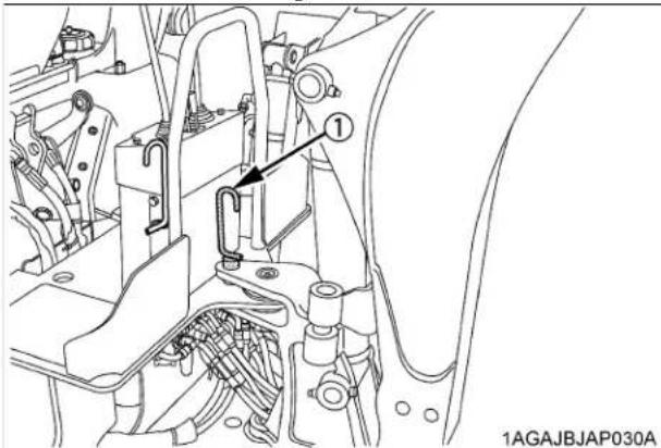
(1) Swing lock pin
-
Stand beside the rear tire, fully close the dipperstick, curl the bucket and lower the boom until the back of bucket contacts the ground.
-
Keep the stabilizer pads at about 381 mm high.

(A) 381 mm
- Raise the rear wheels slightly with the boom and remove the mounting pins.
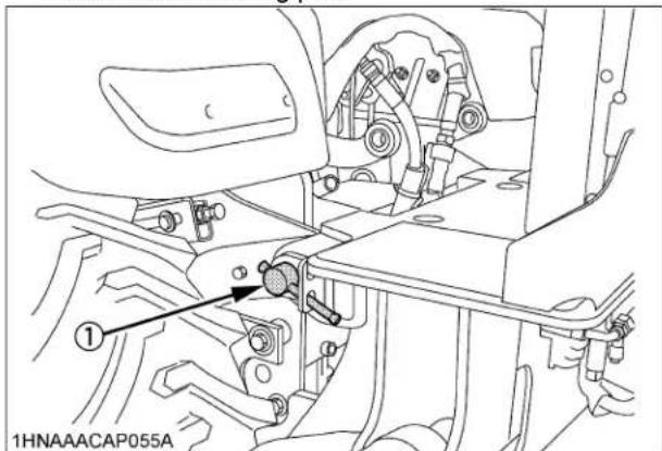
(1) Mounting pin
- Put the mounting pins in the holes on the step of the backhoe.

(1) Mounting pins
- Slowly raise the boom to disengage the backhoe from the tractor.

natural_image
Technical line drawing of an excavator assembly with directional arrows indicating motion (no text or symbols)- Raise the backhoe by operating the stabilizers to the lowering direction until the mount bars hit to the guide stopper on the support hooks.

(1) Guide stopper
(2) Mount bar
(3) Support hook
- Move the tractor forward from the backhoe about 203 mm.
IMPORTANT :
- Be careful not to damage or break the hoses when moving the tractor.
- Lower the main frame and swing frame onto the ground by operating the boom and stabilizer control levers.
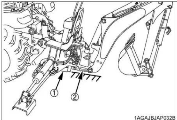
(1) Main frame
(2) Swing frame
10.Shut off the engine and set the parking brake.
11. Slowly release all hydraulic pressure by moving the backhoe hydraulic control levers in all directions.
12.Disconnect hydraulic hoses in the following manner:
(1) Disconnect the inlet, outlet and power beyond hoses from the tractor.
(2) Connect tractor's outlet hose to the coupler of power beyond pipe.

(1) Outlet hose (tractor)
(A) To be connected
(2) Power beyond pipe (tractor)
13.Restart the engine.
Then drive the tractor / loader slowly away from the backhoe.
14.Shut the engine off and remove the key from the tractor. Set the parking brake.
NOTE :
● The entire 3-point hitch can now be reinstalled on the tractor for use with other rear mount implements.
- Be sure that there is sufficient ballast in the rear tires and an implement is attached to the 3-point hitch before using the loader with backhoe removed.
STORAGE OF THE BACKHOE
- Store the backhoe in a dry place.
- Apply a coat of grease to all exposed cylinder rods to prevent rusting.
- If the backhoe is being stored outside, cover the backhoe with suitable weather cover. This will keep moisture, dirt and other airborne debris from getting into the system.
- Repair or replace any worn, damaged or missing parts.
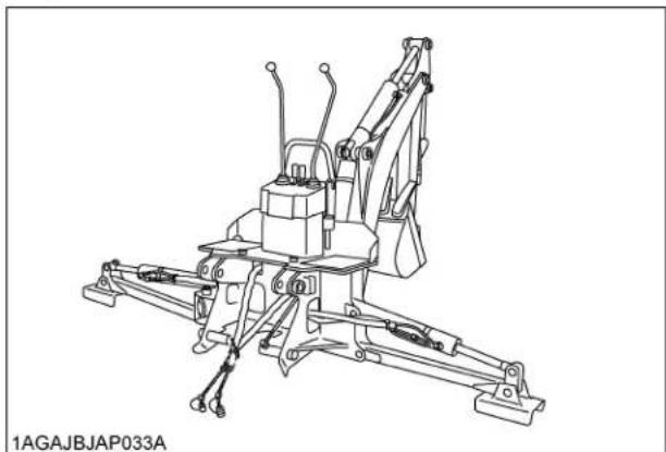
natural_image
Technical line drawing of a mechanical device with articulated arms and levers (no text or symbols)IMPORTANT :
- When storing the backhoe, install the dust caps onto the backhoe's hydraulic nipples to prevent contamination.
REINSTALLING THE BACKHOE

WARNING
To avoid personal injury or death:
- When starting the engine, always sit in the operator's seat.
- When getting off the tractor, make sure that PTO lever is "OFF" and range gear shift lever is in "NEUTRAL". Set the parking brake.
- Keep hands, feet and body from between tractor and backhoe. Never allow any part of body under the machine.

CAUTION
To avoid personal injury:
● Make sure the tractor PTO is disengaged.
IMPORTANT :
● Before reinstalling the backhoe, set the engine speed to low idle.
- Remove the 3-point hitch and / or drawbar. (if equipped)
- Detach the mower, if attached in position.
- Make sure the swing lock pin is installed.
- Slowly back the tractor / loader, centering to the backhoe main frame. Stop the tractor 254 to 304 mm away from the backhoe.
- Shut the engine off and set the parking brake.
- Connect the inlet, outlet and power beyond hoses of the backhoe to the outlet hose, power beyond pipe and return pipe of the tractor.

(1) Inlet hose (Backhoe)
(2) Outlet hose (Backhoe)
(3) Power beyond hose (Backhoe)
(4) Outlet hose (Tractor)
(5) Return pipe (Tractor)
(6) Power beyond pipe (Tractor)
IMPORTANT :
● Make sure both hoses are firmly connected before starting the engine.
- Restart the engine.

WARNING
To avoid personal injury or death:
- Do not move the joystick control lever to the swing position.
- Stand beside the rear tire. Move the boom to fully raising position and raise the backhoe by operating the stabilizers until the mount bar on the backhoe main frame is slightly higher than the tractor main frame support hooks.
NOTE :
- If the support hooks are not parallel to the mount bars, adjust with the stabilizers.

(1) Mount bar
(2) Support hook
- Move the tractor backward until the support hooks on the tractor main frame are just beneath the mount bars on the backhoe main frame.
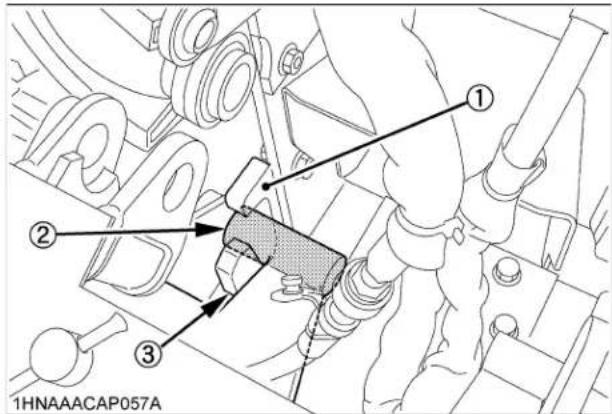
(1) Guide stop
(2) Mount bar
(3) Support hook
-
Lower the mount bars onto the support hooks by operating the stabilizer and boom control levers.
-
Move the boom slowly to the lowering position, and engage the guide plates of the main frame to the bosses of sub frame. Then raise the rear wheels slightly by operating the boom to the lowering direction.

WARNING
To avoid serious injury or death:
● Make sure pins are in all the way slide bar secured and backhoe securely attached.
12.Shut off the engine. Reinstall the mounting pins, and insert the slide bars of the mounting pins to the lower hole of the main frame.
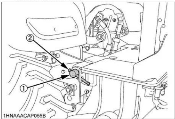
(1) Mounting pin
(2) Slide bar
IMPORTANT :
- If the slide bar of the mounting pins is inserted to the upper hole, the mounting pin comes off and the backhoe might come off. Therefore, please make sure to insert the slide bar to the lower hole.
NOTE :
- Move the tractor / loader / backhoe to an open area and cycle all backhoe functions. This will check their operation and flow oil back through the system, filtering it and refilling each circuit. Check the hydraulic oil level before putting the backhoe into full operation. See "MAINTENANCE OF THE TRACTOR" section for oil type and correct level.
TROUBLESHOOTING
ENGINE TROUBLESHOOTING
If something is wrong with the engine, refer to the table below for the cause and its corrective measure.
| Trouble Cause Countermeasure | |||
| Engine is difficult to start or won't start. | ● No fuel flow. | ● Check the fuel tank and the fuel filter.Replace filter if necessary. | |
| ● Air or water is in the fuel system. | ● Check to see if the fuel line coupler bolt and nut are tight.● Bleed the fuel system.(See "Bleeding Fuel System" in "SERVICE AS REQUIRED" in "PERIODIC SERVICE OF THE TRACTOR" section.)● Remove water from the system and replace the fuel filter. | ||
| ● In winter, oil viscosity increases, and engine revolution is slow. | ● Use oils of different viscosities, depending on ambient temperatures.● Use engine block heater. (Option) | ||
| ● Battery becomes weak and the engine does not turn over quick enough. | ● Clean battery cables and terminals.● Charge the battery.● In cold weather, always remove the battery from the engine, charge and store it indoors.Install it on the tractor only when the tractor is going to be used. | ||
| Insufficient engine power. | ● Insufficient or dirty fuel.● The air cleaner is clogged. | ● Check the fuel system.● Clean or replace the element. | |
| Engine stops suddenly. | ● Insufficient fuel. ● Refuel. | ● Bleed the fuel system if necessary. | |
| Exhaust fumes are colored. | Black | ● Fuel quality is poor.● Too much oil.● The air cleaner is clogged. | ● Change the fuel and fuel filter.● Check the proper amount of oil.● Clean or replace the element. |
| Blue white | ● The inside of exhaust muffler is dumped with fuel.● Injection nozzle trouble.● Fuel quality is poor. | ● Heat the muffler by applying load to the engine.● Check the injection nozzle.● Change the fuel and fuel filter. | |
| Engine overheats. | ● Engine overloaded. | ● Shift to lower gear or reduce load. | |
| ● Low coolant level. | ● Fill cooling system to the correct level;check radiator and hoses for loose connections or leaks. | ||
| ● Loose or defective fan belt. | ● Adjust or replace fan belt. | ||
| ● Dirty radiator core or grille screens. | ● Remove all trash. | ||
| ● Coolant flow route corroded. ● Flush | cooling system. | ||
If you have any questions, consult your local KUBOTA Dealer.
OPTIONS
Consult your local KUBOTA Dealer for further details.
● 18 x 8.5-10 Turf Tire
● 26 x 12.0-12 Turf Tire
● Engine Block heater
For extremely cold weather starting
● Rear Work Light
For high visibility for night work
● Rear wheel weight
● Sunshade for ROPS
KUBOTA Corporation is ...
Since its inception in 1890, KUBOTA Corporation has grown to rank as one of the major firms in Japan.
To achieve this status, the company has through the years diversified the range of its products and services to a remarkable extent. Nineteen plants and 16,000 employees produce over 1,000 different items, large and small.
All these products and all the services which accompany them, however, are unified by one central commitment. KUBOTA makes products which, taken on a national scale, are basic necessities. Products which are indispensable. Products which are intended to help individuals and nations fulfill the potential inherent in their environment. KUBOTA is the Basic Necessities Giant.
This potential includes water supply, food from the soil and from the sea, industrial development, architecture and construction, and transportation.
Thousands of people depend on KUBOTA's know-how, technology, experience and customer service. You too can depend on KUBOTA.
- OPERATOR'S MANUAL
- KUBOTA TRACTOR
- UNIVERSAL SYMBOLS
- FOREWORD
- SAFETY FIRST
- DANGER :
- WARNING :
- CAUTION :
- IMPORTANT :
- NOTE :
- CONTENTS
- SAFE OPERATION ........ -1
- SERVICING....1
- SPECIFICATIONS OF THE TRACTOR 3
- SPECIFICATIONS OF THE LOADER....5
- SPECIFICATIONS OF THE BACKHOE 9
- IMPLEMENT LIMITATIONS 14
- INSTRUMENT PANEL AND CONTROLS.... 16
- PRE-OPERATION CHECK OF THE TRACTOR.... 18
- PRE-OPERATION CHECK OF THE LOADER 19
- PRE-OPERATION CHECK OF THE BACKHOE 23
- 3-POINT HITCH & DRAWBAR 46
- 3-POINT HITCH 47
- HITCH 47
- HYDRAULIC UNIT 49
- 3-POINT HITCH CONTROL SYSTEM....49
- AUXILIARY HYDRAULICS 50
- INSTALLING MOWER....51
- TIRES, WHEELS AND BALLAST....54
- TIRES....54
- WHEEL TREAD 54
- BALLAST 56
- OPERATING THE LOADER....58
- FILLING THE BUCKET 58
- LIFTING THE LOAD 58
- CARRYING THE LOAD 59
- DUMPING THE BUCKET 59
- LOWERING THE BUCKET 59
- OPERATING WITH FLOAT CONTROL 59
- LOADING FROM A BANK 60
- PEELING AND SCRAPING 60
- LOADING LOW TRUCKS OR SPREADERS FROM A PILE....61
- BACKFILLING 61
- HANDLING LARGE HEAVY OBJECTS....62
- VALVE LOCK 62
- Boom Lock (Spill guard model only).... 63
- SAFE OPERATION
- TRACTOR
- Read and understand this manual carefully before operating the tractor.
- ◆CAB, ROPS
- Starting
- ◆Working
- ◆Safety for children
- ◆Operating on slopes
- ◆Driving the tractor on the road
- PARKING THE TRACTOR
- USING 3-POINT HITCH
- SERVICING THE TRACTOR
- LOADER
- AFTER OPERATING THE LOADER
- SERVICING THE LOADER
- BACKHOE
- DRIVING THE TRACTOR ON THE ROAD
- SERVICING THE BACKHOE
- DANGER, WARNING AND CAUTION LABELS OF THE TRACTOR
- CAUTION
- TO AVOID PERSONAL INJURY:
- WARNING
- TO AVOID PERSONAL INJURY WHEN RAISING OR FOLDING ROPS:
- DANGER
- TO AVOID POSSIBLE INJURY OR DEATH FROM A MACHINE RUNAWAY:
- DANGER, WARNING AND CAUTION LABELS OF THE LOADER
- TO AVOID PERSONAL INJURY :
- TO AVOID INJURY FROM FALLS OR BEING CRUSHED :
- ▲WARNING
- DANGER, WARNING AND CAUTION LABELS OF THE BACKHOE
- DANGER, WARNING AND CAUTION LABELS OF THE ATTACHMENTS
- TO AVOID PERSONAL INJURY OR DEATH CAUSED BY ROLLOVER
- TO AVOID INJURY FROM CRUSHING:
- CARE OF DANGER, WARNING AND CAUTION LABELS
- SERVICING
- ◆Warranty
- ◆Scrapping the tractor and its procedure
- SPECIFICATIONS OF THE TRACTOR
- SPECIFICATIONS OF THE LOADER
- LOADER TERMINOLOGY
- SPECIFICATIONS OF THE BACKHOE
- BACKHOE SPECIFICATIONS
- Specifications
- ■Lift Capacity (Per SAE J31)
- BACKHOE TERMINOLOGY
- IMPLEMENT LIMITATIONS
- INSTRUMENT PANEL AND CONTROLS
- ILLUSTRATED CONTENTS
- ■Foot and Hand Controls
- PRE-OPERATION CHECK OF THE TRACTOR
- DAILY CHECK
- Check item
- PRE-OPERATION CHECK OF THE LOADER
- LUBRICATION
- TRANSMISSION FLUID
- REAR BALLAST
- ◆Liquid ballast in rear tires
- [Spill guard model]
- RATED OPERATING LOAD (SPILL GUARD MODEL ONLY)
- TIRE INFLATION
- TEST OPERATION
- REMOVING AIR FROM HYDRAULIC SYSTEM
- PRE-OPERATION CHECK OF THE BACKHOE
- OPERATOR'S SEAT
- Seat Belt
- BALLAST
- STARTING THE ENGINE
- Make sure the parking brake is set.
- Place the PTO clutch lever in "OFF" position.
- Place the speed set rod in "OFF" position.
- ◆Check Easy Checker(TM) Lamps:
- Turn the key to "PREHEAT" position and hold it for about 2 to 3 seconds.
- Turn the key to "START" position and release it when the engine starts.
- ■Cold Weather Starting
- ■Block Heater (Option)
- Check to see that all the lamps on the Easy Checker(TM) are "OFF".
- STOPPING THE ENGINE
- WARMING UP
- ■Warm-up and Transmission Oil in the Low Temperature Range
- JUMP STARTING
- ■Do not Operate the Tractor at Full Speed for the First 50 Hours.
- ■Changing Lubricating Oil for New Tractors
- BOARDING AND LEAVING THE TRACTOR
- OPERATING FOLDABLE ROPS
- ■To Fold the ROPS
- ■To Raise the ROPS to Upright Position
- ■Adjustment of Foldable ROPS
- Adjust the operator's position and engage the seat belt.
- ◆Travel adjustment
- ◆Tilt adjustment
- Selecting Light Switch Positions.
- ■Head Light Switch
- Hazard Light Switch
- ■Turn Signal Light Switch
- Checking the Brake Pedal.
- Brake Pedal
- Start the engine.
- Raise the Implement. (see "HYDRAULIC UNIT" section.)
- Select the Travel Speed.
- ■Range Gear Shift Lever (Hi-Lo)
- ■Front Wheel Drive Lever
- Accelerate the Engine.
- ■Hand Throttle Lever
- Unlock the Parking Brake.
- ■Parking Brake Pedal
- Depress the Speed Control Pedal.
- ■Speed Control Pedal
- Forward Pedal
- Reverse Pedal
- ■Speed Set Device
- ◆To engage Speed Set Device
- ◆To disengage Speed Set Device
- STOPPING
- ■Stopping
- CHECK DURING DRIVING
- ■Immediately Stop the Engine if:
- ■Easy Checker(TM)
- Engine oil pressure
- Electrical charge
- ■Fuel Gauge
- Coolant Temperature Gauge
- Overheat indication:
- If the coolant temperature indicator on the Easy Checker(TM) comes on:
- Check the following items:
- ■Hourmeter/Tachometer
- PARKING
- ACCESSORY
- ■12V Electric Outlet
- OPERATING TECHNIQUES
- ■Differential Lock
- ■Operating the Tractor on a Road
- ■Operating on a Slopes and Rough Terrain
- ■Transport the Tractor Safely
- ■Directions for Use of Power Steering
- REVERSING THE SEAT
- PTO
- PTO OPERATION
- ■PTO Select Lever
- ◆Mid-PTO
- ◆Mid-Rear PTO
- ◆Rear PTO
- ■PTO Clutch Lever
- ■PTO Shaft Cover and Shaft Cap
- ■Stationary PTO
- ■PTO Drive Shaft
- 3-POINT HITCH & DRAWBAR
- 3-POINT HITCH
- ■Attaching and detaching implements
- ■Lifting Rod (Right)
- ■Top Link
- Check Chains
- HITCH
- ■Removing the 3-Point Hitch
- ■Installing the 3-Point Hitch
- HYDRAULIC UNIT
- 3-POINT HITCH CONTROL SYSTEM
- Hydraulic Control
- ■3-point Hitch Lowering Speed
- AUXILIARY HYDRAULICS
- Hydraulic Outlet
- INSTALLING MOWER
- ■Cutting Height Control Dial
- ■Hydraulic Control Unit Use Reference Chart
- TIRES, WHEELS AND BALLAST
- TIRES
- Inflation Pressure
- Dual Tires
- WHEEL TREAD
- Front Wheels
- Rear Wheels
- Front Ballast
- ■Rear Ballast
- FILLING THE BUCKET
- LIFTING THE LOAD
- CARRYING THE LOAD
- DUMPING THE BUCKET
- LOWERING THE BUCKET
- OPERATING WITH FLOAT CONTROL
- LOADING FROM A BANK
- PEELING AND SCRAPING
- LOADING LOW TRUCKS OR SPREADERS FROM A PILE
- BACKFILLING
- HANDLING LARGE HEAVY OBJECTS
- VALVE LOCK
- ■Boom Lock (Spill guard model only)
- [To Set the Boom Lock]
- [To Remove the Boom Lock]
- ◆Storing the boom lock
- SPILL GUARD (SPILL GUARD MODEL ONLY)
- ■Adjustment of spill guard link
- ◆Adjustment of spill guard link
- ATTACHING ATTACHMENTS
- [Option for LA240A, LA240A AU-SG]
- DETACHING ATTACHMENTS
- DISMOUNTING THE LOADER
- ATTACHMENTS
- Bucket
- Pallet fork
- ASSEMBLE PALLET FORK
- BACKHOE CONTROLS
- ■Boom & Swing Lever
- ■Dipperstick & Bucket Lever
- ■Stabilizer Control Levers
- PLACING THE STABILIZERS
- ■Dipperstick Digging
- ■Spoil Pile Location
- ■Straight Wall or Cemetery Digging
- ■Stabilizer pads (Option)
- TRANSPORTING
- ■Driving to the Job-site
- ■Trailer Transporting
- MAINTENANCE OF THE TRACTOR
- ◆Engine Oil:
- ◆Fuel:
- ◆Transmission Oil:
- PERIODIC SERVICE OF THE TRACTOR
- HOW TO OPEN THE HOOD
- Hood
- ■Engine Cover
- ■Walk Around Inspection
- ■ Checking and Refueling
- ■ Checking Engine Oil Level
- ■ Checking Transmission Fluid Level
- ■ Checking Coolant Level
- ■Cleaning Panel and Radiator Screen
- ■ Checking Brake Pedal
- ■ Checking Gauges, Meters and Easy Checker(TM)
- ■ Checking Head Light, Hazard Light etc.
- ■ Checking Seat Belt and ROPS
- ■ Checking and Cleaning of Electrical Wiring and Battery Cables
- Inspect the following Regularly:
- ■ Checking Movable Parts
- EVERY 50 HOURS
- ■ Lubricating Grease Fittings
- ■ Checking Engine Start System
- ◆Preparation before testing.
- ◆Test 1: Switch for the speed control pedal
- ◆Test 2: Switch for the PTO clutch lever
- ■ Checking OPC System
- ◆ Test 1: Switches for the operator's seat and the speed control pedal
- ◆ Test 2: Switches for the operator's seat and the PTO clutch lever.
- ■ Checking Wheel Bolt Torque
- EVERY 100 HOURS
- Battery
- ◆Battery for storage
- ■Cleaning Air Cleaner Element
- ◆Evacuator Valve
- ■ Checking Fuel Lines and Fuel Filter
- ■Adjusting Fan belt Tension
- ■Adjusting HST Neutral Spring (for Speed Control Pedal)
- ■Adjusting Brake Pedal
- EVERY 200 HOURS
- ■Replacing Engine Oil Filter
- ■Changing Engine Oil
- ■Replacing Transmission Oil Filter
- ■Checking Radiator Hoses and Clamps
- ◆Precaution at Overheating
- ■ Checking Intake Air Line
- ■Adjusting Toe-in
- ◆Adjusting procedure
- ■ Checking Power Steering Line
- EVERY 400 HOURS
- ■Adjusting Front Axle Pivot
- ■Changing Transmission Fluid
- ■Cleaning Transmission Strainer
- ■Changing Front Axle Case Oil
- EVERY 500 HOURS
- ■Replacing Fuel Filter Element
- EVERY 800 HOURS
- ■Adjusting Engine Valve Clearance
- EVERY 1500 HOURS
- ■ Checking Fuel Injection Nozzle Injection Pressure
- EVERY 3000 HOURS
- ■ Checking Injection Pump
- EVERY 1 YEAR
- ■Replacing Air Cleaner Element
- EVERY 2 YEARS
- ■Flushing Cooling System and Changing Coolant
- Anti-Freeze
- ■Replacing Radiator Hose (Water pipes)
- ■Replacing Power Steering Hose
- ■Replacing Fuel Lines
- ■Replacing Engine Breather Hose
- ■Replacing Intake Air Line
- SERVICE AS REQUIRED
- ■Bleeding Fuel System
- ■Replacing Fuse
- ■Replacing Light Bulb
- MAINTENANCE OF THE LOADER
- RE-TIGHTENING OF HARDWARE
- ■Tightening Bolts and Nuts
- DAILY CHECKS
- ■ Checking main frame bolt and nut torque
- MAINTENANCE OF THE BACKHOE
- BUCKET SERVICE
- ■Changing the Backhoe Bucket
- ■Changing the Bucket Teeth
- STORAGE OF THE TRACTOR
- TRACTOR STORAGE
- REMOVING THE TRACTOR FROM STORAGE
- REMOVING THE LOADER
- STORAGE OF THE LOADER
- REINSTALLING THE LOADER
- [Spill guard model only]
- REMOVING THE BACKHOE
- REMOVAL OF THE BACKHOE
- STORAGE OF THE BACKHOE
- REINSTALLING THE BACKHOE
- TROUBLESHOOTING
- ENGINE TROUBLESHOOTING
- OPTIONS
- KUBOTA Corporation is ...
Brand : KUBOTA
Model : LA240A
Category : Agricultural tractor