
CH133RR - Thermostat Fantini Cosmi - Free user manual and instructions
Find the device manual for free CH133RR Fantini Cosmi in PDF.


| Product Type | Electronic Thermostat |
| Brand | Fantini Cosmi |
| Model | CH133RR |
| Power Supply | 2 x AAA batteries (1.5 V) |
| Temperature Range | 5°C to 35°C |
| Accuracy | ±0.5°C |
| Display Type | LCD with backlight |
| Installation | Wall-mounted (flush or surface) |
| Programming | Weekly programmable with 6 time slots per day |
| Dimensions (mm) | 85 x 85 x 28 |
| Weight | 150 g (including batteries) |
| Material | ABS plastic, white |
| Protection Class | IP20 |
| Functions | Heating/Cooling control, Frost protection, Holiday mode |
| Compatibility | Gas, electric, heat pump systems (on/off) |
| Warranty | 2 years (manufacturer) |
| Certifications | CE, RoHS |
| Maintenance | Wipe with a dry cloth; clean display gently |
| Repairability | Replaceable batteries; professional repair recommended for electronics |
| Safety | Overheat protection; low battery indicator |
Frequently Asked Questions - CH133RR Fantini Cosmi
User questions about CH133RR Fantini Cosmi
0 question about this device. Answer the ones you know or ask your own.
Ask a new question about this device
Download the instructions for your Thermostat in PDF format for free! Find your manual CH133RR - Fantini Cosmi and take your electronic device back in hand. On this page are published all the documents necessary for the use of your device. CH133RR by Fantini Cosmi.
USER MANUAL CH133RR Fantini Cosmi
Flush mounting thermostat for fan-coils, 3 speeds + automatic
CH133RR is a kit composed by a thermostat for fan-coil (2 or 4 pipes) and a remote actuator. It controls the room temperature both in heating and cooling mode and it is able to control up to two valves and the speed of the fan coil (3 speeds or automatic function)
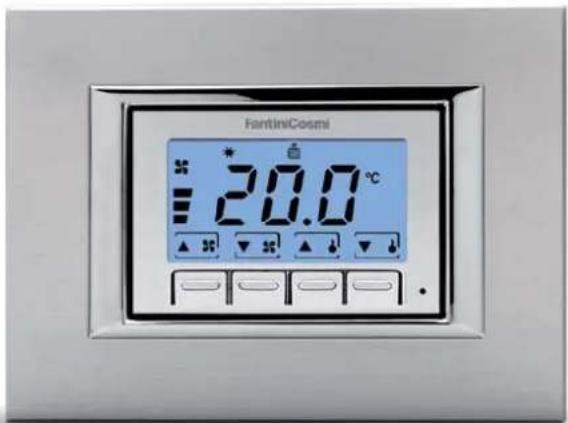
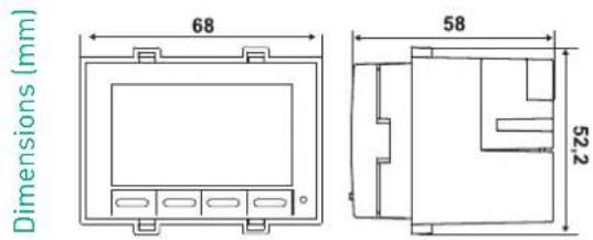
KIT COMPOSITION TABLE
| KIT CODE | THERMOSTAT CODE | ACTUATOR CODE | CONNECTION TYPE | |||
| CH133RR | CH133 | CH172D | 2 wires | |||
| CODICE Mounting Temperature | regulation range | Body admissible temperature | Power supply N° relay Power supply | Protection degree | ||
| CH133 wall mounting 2 ÷ 40 °C 45 °C actuator CH172D - - IP20 | ||||||
| CH172D | 6-module DIN rail | 45 °C | 230V-50Hz | 5 | 5(3)A 250Vac | IP00 |
| CH172DS* | 6-module DIN rail | 45 °C | 230V-50Hz | 5 | 5(3)A 250Vac | IP00 |
*CH172DS is used to control more fan-coils.
natural_image
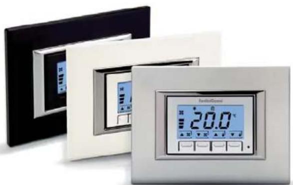
Modern home appliances including a digital display showing 20.0°C, with no visible text or symbols on the devices themselves."MULTIPLATE" KIT
Suitable for all the plates (3 module) thanks to the KIT consisting of: programmable thermostat, coloured plates(white, silver and anthracite), frames and adaptors
CARATTERISTICHE ELETTRICHE
Power supply from a remote actuator
Remote actuator with 5 output relays, voltage 250 Vac.
Contacts rating 5(3)A.
4-TUBE INSTALLATION
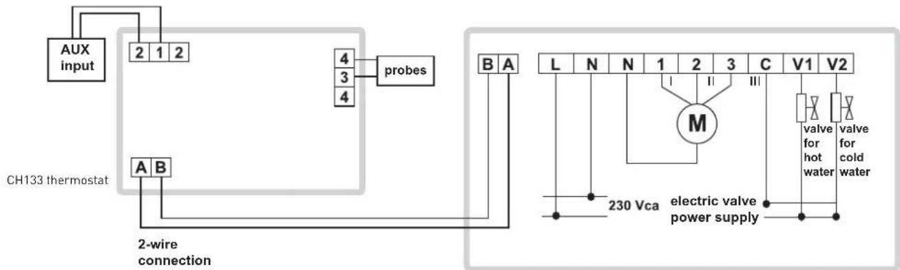
remote actuator CH172D
2-TUBE INSTALLATION
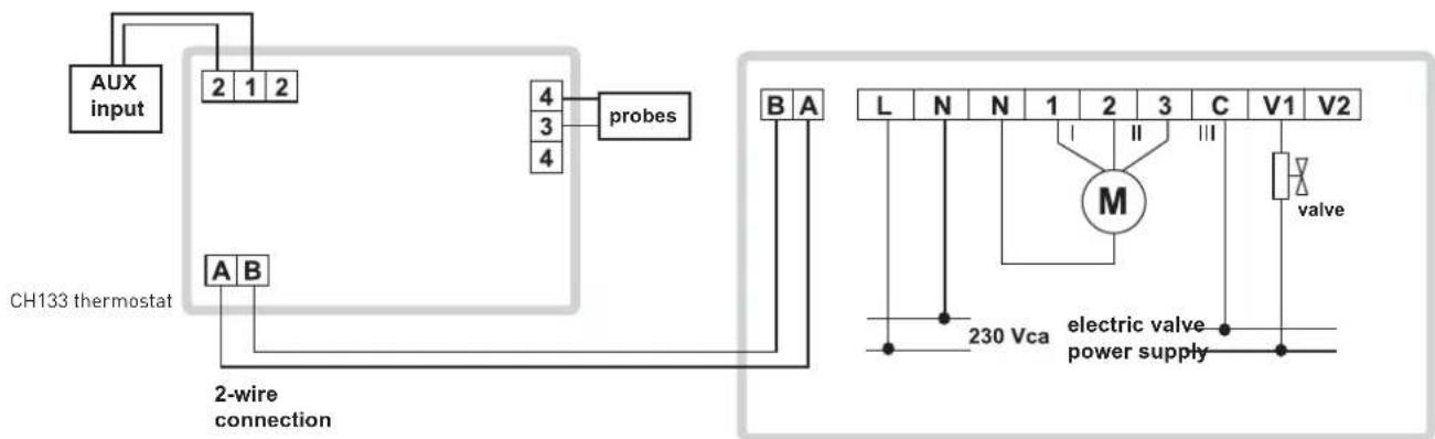
remote actuator CH172D
AUX INPUT CONFIGURATION
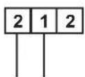
Input supplied with
24 Vdc/Vac
not used
ON/OFF
SUMMER/WINTER
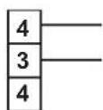
not used
return probes
SUMMER/WINTER control
■ minimum window/thermostat contact
■ reverse contact (minimum window/thermostat)
HOMOLOGATION AND STANDARDS
Complies with EN60730-1, EN60730-2-9.
Complies with 2006/95/CE, 2004/108/CE, 1993/68/CE
ErP: ErP Class IV; 2% (Reg. EU 811/2013 -813/2013)
CE EAC
INSTALLATION
Flush-mounting in 3-module 503 embedded boxes by means of 2 screws (supplied).
Two-wire connection with the user.
Install the thermostat at 1,5 meters above the floor, away from kitchens, heat sources, windows and doors.
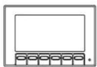
Can be applied, without any connection accessory, the following plates:
INCLUDED IN THE PACKAGE:

A
B
3 COVER "A" for Bticino Axolute, Ave Sistema 44, Eikon Evo and Arkè
□ WHITE
SILVER
ANTHRACITE
3 COVER "B"
□ WHITE
SILVER
ANTHRACITE
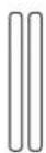
3 PAIRS OF ADAPTERS
□ WHITE
SILVER
ANTHRACITE
1 PAIR OF ADAPTERS for Bticino Matix
□ WHITE
COMPATIBLE PLATES
| MODELS COVER | TYPE | FRAME TYPE | LATERAL ADAPTERS |
| Bticino Living International and Transizione Piana B 1 NO | |||
| Bticino Living Light Air B 3 NO | |||
| Bticino Light, Light tech B 1 NO | |||
| Bticino Axolute A 1 NO | |||
| Bticino Axolue Air A 4 NO | |||
| Bticino Matix B 2 | YES (included) | ||
| Vimar Idea e Rondò | B 2 | YES | |
| Vimar Plana e Eikon | B 1 NO | ||
| Vimar Eikon Evo | A 3 NO | ||
| Vimar Arké | A 3 NO | ||
| Gewiss Chorus One, Lux, Art | B 2 NO | ||
| Ave sistema 45: Zama, Banquise, Yes, Ral | B 2 | YES | |
| Ave sistema 44: Zama, Personal, Tecnopolimero | A 1 NO | ||
| Legrand Cross, Vela quadra, Vela tonda | B 2 | NO | |
| ABB Elos | B 4 | YES | |
| ABB Mylos | B 4 | NO |
OPERATION
CH133 is supplied from the actuator and is able to drive two valves and also control a 3-speed fan-coil motor.
The backlight wide display shows the measured temperature, fan speed, the running program and the selected season.
The settings and data are stored in a permanent (nonvolatile) memory capable of keeping them even in the absence of power supply.
CH133 have 3 different operating modes:
■ COMFORT: with the comfort operating mode, the thermostat regulates the heating or cooling installation operation in order to always keep the same prescribed comfort temperature
ECONOMY with the ECONOMY operating mode, the thermostat regulates the heating or cooling installation operation in order to always keep
■ the same prescribed economy temperature
OFF), this function can be achieved by setting the fan speed to zero. In this case, the thermostat does not perform the regulation. The system will switch OFF completely and on display will appear the message "OFF".
SUMMER-WINTER
Suitable to control heating and air conditioning systems
FAN SPEED SELECTION
■ MANUAL: fan speed can be set manually to free fixed levels (minimum, medium, maximum).
AUTO: if the speed is set in Auto, the thermostat sets automatically the appropriate speed according to the difference between the set-point and the ambient temperature.
TECHNICAL MENU
CH133 has a technical menu to configure it for every installation with the following functions:
SYSTEM TYPE
2-TUBE SYSTEM: the thermostat will drive only the valve (on /off type) used for heating both during the heating and the cooling; in fact, the valve will control both hot water and cold water
4-TUBE SYSTEM: the thermostat will drive one valve (on /off type) used for heating, plus one additional valve (on /off type) used for cooling, based on the needs of the environment
EXTERNAL PROBE
■ RESUMPTION: instead of the probe incorporated into the thermostat, an external probe can be used to read the ambient temperature and carry out heat regulation. Typically, this probe will be positioned under the fan-coil where air is sucked
CHANGEOVER: the external temperature probe can be placed on the fan-coil delivery tube of a 2-tube system to perform automatic changeover between the "Summer" operation and the "Winter" operation
MINIMUM WINDOW /THERMOSTAT CONTACT: when the contact is open, the thermostat will carry out heat regulation; when it is closed, the heat regulation will not be carried out.
INVERTED MINIMUM WINDOW /THERMOSTAT CONTACT : the window contact will operate with an inverted logic with respect to the statements made in previous step 3.
- NONE: the external probe input will not be controlled by the thermostat.
DISPLAY VISUALIZATION
AMBIENT TEMPERATURE: the ambient temperature will be shown on the display
SET-POINT: the current set point will be shown on the display
CENTRAL INPUT CONFIGURATION
■ ON/OFF: in the event that several thermostats have been installed, you may decide either to drive all of them in the normal
operation condition (ON) or taking advantage of the OFF function by controlling them through a central point. The thermostat will be configured to OFF when the input is powered with 24 V (d.c. with no polarity obligation or a.c.); on the contrary, it will remain active when the input is free from voltage
SUMMER /WINTER : as in the previous case, the thermostat will be configured to "Summer" mode when the input is powered with 24 V; on the contrary, it will remain active in the "Winter" mode when the input is free from voltage.
- NONE: the thermostat will not carry out any operation, whatever the input status
SUMMER VALVE TYPE
■ NORMALLY OPEN : in this case, the water flow is normally open and will be closed when the valve is supplied.
■ NORMALLY CLOSED : when the valve is energized, it will open the water flow.
WINTER VALVE TYPE
NORMALLY OPEN : in this case, the water flow is normally open and will be closed when the valve is supplied.
■ NORMALLY CLOSED : when the valve is energized, it will open the water flow
AMBIENT TEMPERATURE CORRECTION
It can be adjusted from -4.0 to 4.0°C. This parameter is used to correct the acquired ambient temperature. In fact, in some installations, the ambient temperature reading may not be satisfying, due to the probe location (i.e. internal or resumption). With this parameter, a constant value upon reading can be added to or subtracted from.
"WINTER" LOWER LIMIT SET-POINT TEMPERATURE
It can be adjusted from 2.0 to 40.0°C. It represents the lower limit for all the set-points (Comfort and Economy) in the heating mode.
"WINTER" UPPER LIMIT SET-POINT TEMPERATURE
It can be adjusted from 2.0 to 40.0°C. It represents the upper limit for all the set-points (Comfort and Economy) in the heating mode.
"SUMMER" LOWER LIMIT SET -POINT TEMPERATURE
It can be adjusted from 2.0 to 40.0°C. It represents the lower limit for all the set-points (Comfort and Economy) in the cooling mode
"SUMMER" UPPER LIMIT SET -POINT TEMPERATURE
It can be adjusted from 2.0 to 40.0°C. It represents the upper limit for all the set-points (Comfort and Economy) in the cooling mode
CHANGEOVER LOWER THRESHOLD
It can be adjusted from 0 to 24^ . It defines the changeover function lower threshold. Below this temperature, the thermostat will be set to the cooling mode.
CHANGEOVER LOWER THRESHOLD
It can be adjusted from 26 to 48^ . It defines the changeover function upper threshold. Above this temperature, the thermostat will be set to the heating mode.
TEMPERATURE RANGE
■ Possibility to visualize Celsius or Fahrenheit temperature values
■ Settable differential.
FEATURES
Auxiliary input for minimum window and/or thermostat contact using an external probe;
Dimensions (L x A x P) 68 x 52 x 58 mm;
External probe distance 10 m max;
Thermal gradient: 4K/h;
Maximum cable length actuator: 100m:
Screwed terminals;
□ double insulation.
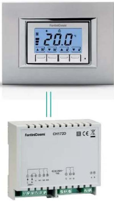
A CH133 can control up to 5 fan-coil units simultaneously, using only two cables for connecting to the actuators. One of these actuators must be a CH172D, while others, maximum four, will be CH172DS.
CONNECTION EXAMPLE 1 FAN-COIL
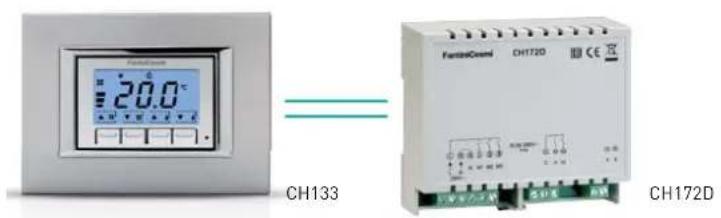
CONNECTION EXAMPLE MOST FAN-COIL (FROM 2 TO 5)
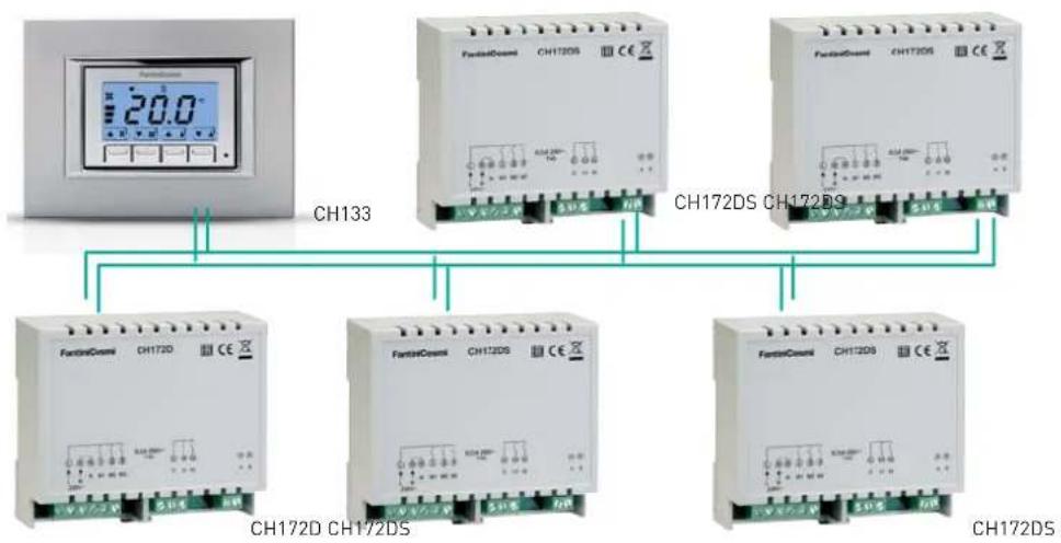
flowchart
graph TD
    A["Digital Display 20.0"] --> B["CH133"]
    C["FantaCount CH172DS"] --> D["CH172DS"]
    E["FantaCount CH172DS"] --> F["CH172DS"]
    G["FantaCount CH172DS"] --> H["CH172DS"]
    I["FantaCount CH172DS"] --> J["CH172DS"]
    K["Ch172DS"] --> L["CH172DS"]
    M["Ch172DS"] --> N["Ch172DS"]
    O["Ch172DS"] --> P["Ch172DS"]
    Q["Ch172DS"] --> R["Ch172DS"]
    S["Ch172DS"] --> T["Ch172DS"]
    U["Ch172DS"] --> V["Ch172DS"]
    W["Ch172DS"] --> X["Ch172DS"]
    Y["Ch172DS"] --> Z["Ch172DS"]
- Flush mounting thermostat for fan-coils, 3 speeds + automatic
- "MULTIPLATE" KIT
- CARATTERISTICHE ELETTRICHE
- HOMOLOGATION AND STANDARDS
- INSTALLATION
- OPERATION
- SUMMER-WINTER
- FAN SPEED SELECTION
- TECHNICAL MENU
- SYSTEM TYPE
- EXTERNAL PROBE
- DISPLAY VISUALIZATION
- CENTRAL INPUT CONFIGURATION
- SUMMER VALVE TYPE
- WINTER VALVE TYPE
- AMBIENT TEMPERATURE CORRECTION
- "WINTER" LOWER LIMIT SET-POINT TEMPERATURE
- "WINTER" UPPER LIMIT SET-POINT TEMPERATURE
- "SUMMER" LOWER LIMIT SET -POINT TEMPERATURE
- "SUMMER" UPPER LIMIT SET -POINT TEMPERATURE
- CHANGEOVER LOWER THRESHOLD
- TEMPERATURE RANGE
- FEATURES
Brand : Fantini Cosmi
Model : CH133RR
Category : Thermostat