
6202 - Car alarm GEMINI - Free user manual and instructions
Find the device manual for free 6202 GEMINI in PDF.


| Product Type | Car Alarm System |
| Brand | Gemini |
| Model | 6202 |
| Power Supply | 10.5 – 14.5 Vdc |
| Current Consumption (Armed) | 14 mA |
| Current Consumption (Disarmed) | 9 mA |
| Operating Temperature | -30°C to +85°C |
| Protection Rating | IP 54 |
| Siren Sound Level | >118 dB at 1 meter |
| Alarm Cycle Duration | 30 seconds |
| Engine Immobilization Relay Rating | 8 A continuous |
| Central Door Locking Relay Rating | 10 A continuous |
| Backup Battery Voltage | 7.2 V |
| Backup Battery Capacity | 170 mAh |
| Sensors | Perimetric and Volumetric (ultrasonic optional for GE-KT versions) |
| Remote Controls Included | 2-button transmitter (art. 5009E) and 1-button transmitter (art. 6108E) |
| Frequency | ETSI 300 220 compliant |
| Homologation | European Directive 95/56 CE (e12*95/56 0011*00) |
| Installation Location | Engine compartment, protected from water spray; ultrasonic heads on windscreen pillars |
| Special Functions | Panic, Passive Arming, Self-learning of transmitters, Ultrasonic Exclusion, LED Memory, Dip-switch Programming |
| Maintenance | Avoid steam cleaning engine; backup battery charges only when system disarmed and ignition ON |
Frequently Asked Questions - 6202 GEMINI
User questions about 6202 GEMINI
0 question about this device. Answer the ones you know or ask your own.
Ask a new question about this device
Download the instructions for your Car alarm in PDF format for free! Find your manual 6202 - GEMINI and take your electronic device back in hand. On this page are published all the documents necessary for the use of your device. 6202 by GEMINI.
USER MANUAL 6202 GEMINI
The undersigned,qualified installer,attests to have personally fitted the here described Vehicle Security System following the manufacturer instructions.
System 6202 or 6203 is a compact alarm that includes sensors and siren. It can be installed on cars with petrol engine equipped with 12 volts battery (negative ground).
DESCRIPTION
GEMINI 6203
- Remote controlled, self-powered, compact alarm unit with dynamic code.
- Blinker and electronic siren, central door locking control, electric windows and sunroof closure (for selected vehicles equipped with pac-comfort" system).
- Perimetric and volumetric protection (only for 6202GE-KT and 6203GE-KT).
- LED's memory.
- Engine immobilisation.
- Battery backup charger activated by ignition key switched on, without drawing current
during alarm on.
GEMINI 6202.
As 6203 not self-powered.
Both systems are supplied with a 2 buttons transmitter (art. 5009E) and a 1 button transmitter (art. 6108E) and 2 keys for ON-OFF.
| WIRING CONNECTIONS(DISCONNECT THE NEGATIVE TERMINAL OF THE BATTERY AND ONLY RE-CONNECT AFTER THE INSTALLATION IS COMPLETE) | ||
| Earth | ↔↔ | BROWN |
| Battery positive terminal | ↔↔ | RED |
| Engine immobilisation | ↔↔ | GREY |
| Ignition live | ↔↔ | YELLOW |
| Direction indicator lights | ↔↔ | ORANGE |
| Door pin switch | ↔↔ | GREEN-BROWN |
| Boot/bonnet pin switches | ↔↔ | GREEN |
| Positive alarm armed | ↔↔ | PINK |
| Sensors inlet | ↔↔ | GREEN-BLACK |
| Outlet negative control additional siren | ↔↔ | YELLOW-BLACK |
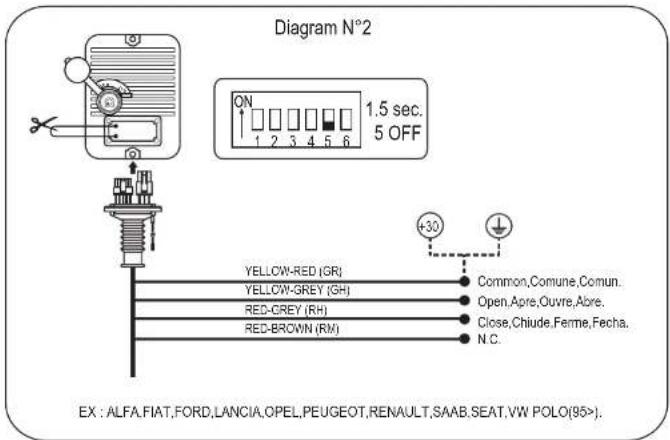
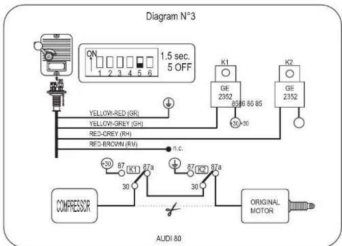
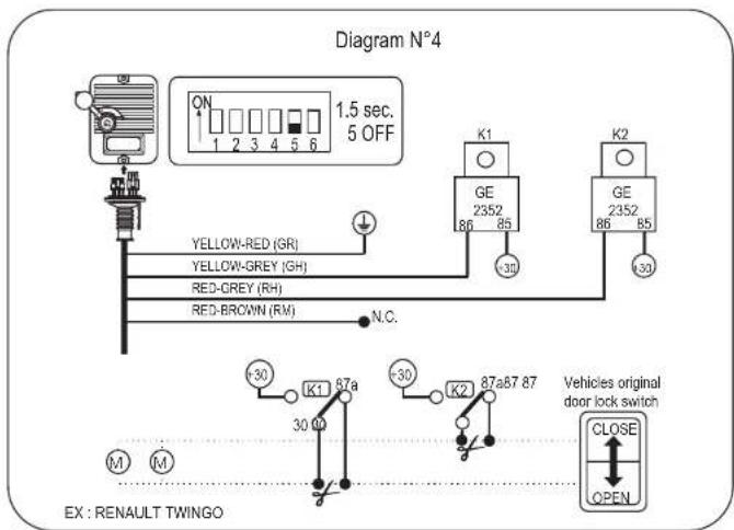
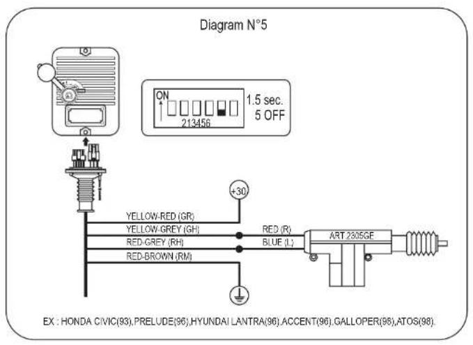
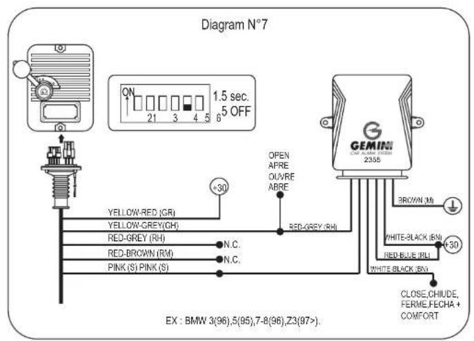
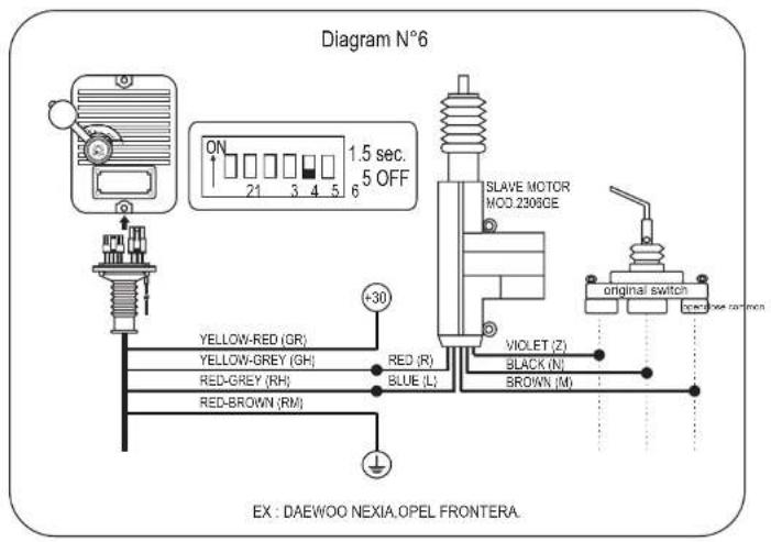
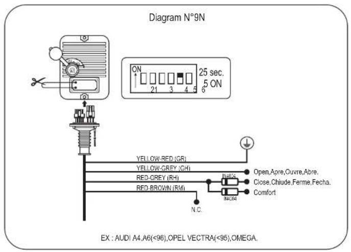
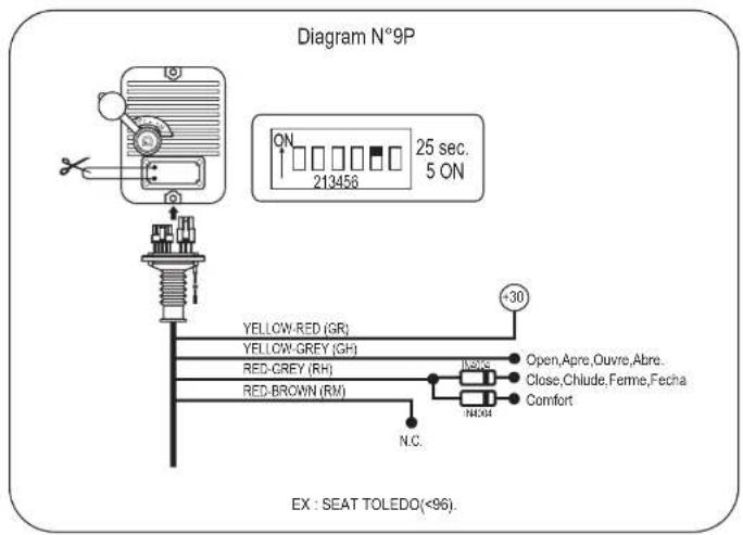
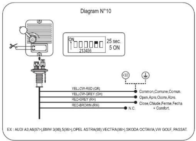
| Central door locking | ↔↔ | YELLOW-RED,BROWN-RED,YELLOW-GREY,RED-GREY |
| NOTE: The wiring harness has two BLACK connectors. Connect the 4 pin BLACK connector to the ultrasound module and the 2 pin BLACK connector to the LED. | ||
USEFUL SUGGESTIONS FOR THE INSTALLATION
- Connect the power feed wire to the battery positive terminal and the earth directly to the vehicle frame.
- On catalysed vehicles the engine immobilisation must be carried out on the fuel pump.
-
Avoid routing connection wires next to interference sources (sparking plug cables, high voltage coil)
-
Install the alarm in the engine compartment protected from water spray.
- If you install an ultrasonic module, the ultrasonic heads must be positioned at the top of each windscreen pillar and must be pointing at each opposite diagonal corner away from the facia outlets.
USER
WORKING DESCRIPTION
ALARM ACTIVATION: push on the transmitter's BLACK button. The activation is signalled by one pulse of the direction indicator lights and one acoustic signal (can be isolated).
ALARM ACTIVATION-ISOLATING ULTRASONICS AND VOLTAGE DROP: push on the transmitter's RED button. The activation is signalled by 2 pulses of the direction indicator lights and two acoustic signals (can be isolated). To de-activate this function, while alarm de-activated, turn the vehicle ignition key to ON position for 15 seconds.
ALARM DE-ACTIVATION: push on the transmitter's BLACK button. The de-activation is signalled by 3 pulses of the direction indicator lights and 3 acoustic signals (can be isolated). 5 pulses of the direction indicator lights if an alarm condition has occurred.
SPECIAL FUNCTIONS
PANIC: The panic function is obtained by pushing on the transmitter's RED button (art. 5009E) while the alarm is activated. The siren will activate for 10 sec.. To de-activate the siren within 10 sec. push again on the transmitter's RED button.
PASSIVE ARMING: Position the dip-switch Nr. 3 in ON position. The passive arming will activate 30 sec. after the engine is switched off if one door is opened. This function allows to activate the alarm and the engine immobilisation without controlling the central door locking.
SELF-LEARNING OF THE CODE OF A NEW TRANSMITTER: While alarm de-activated, position the dip-switch Nr. 4 to ON; turn the ignition key to ON position and push on the transmitter's button. The LED will signal the learning by one flashing. Turn again the ignition key to OFF position and the dip-switch Nr. 4 to OFF position, verifying with the transmitter the activation/de-activation of the alarm. It is possible to codify a maximum number of 4 transmitters.
ULTRASONIC EXCLUSION THROUGH THE ONE-CHANNEL TRANSMITTER (art. 6108E): While alarm deactivated, turn the ignition key to ON position, push on the transmitter's button. The LED will signal the memorisation of the ultrasound exclusion with a 2 sec. flashing.
LED's MEMORY: While alarm de-activated it is possible to verify if an alarm condition has occurred.
The exit delay period is 15 sec. for each alarm.
To stop the LED flashing turn the ignition key to ON position.
| Signalling LED Alarm triggering | |
| *** | Ignition live. |
| *** | Voltage drop sensor and external sensors. |
| *** | Wires cut, door and boot/bonnet pin switches. |
| ***** | Lack of feed , alarm by OFF-ON. |
| LED OFF (2 seconds) * LED ON (1 second) | |
| DIP SWITCH PROGRAMMING TABLE | |||
| 1 | ON | Current drawn active | |
| 1 | OFF | Current drawn isolated | |
| 2 | ON | Acoustic activation/de-activation isolated | |
| 2 | OFF | Acoustic activation/de-activation active | |
| 3 | ON | Passive arming active | |
| 3 | OFF | Passive arming isolated | |
| 4 | ON | Self-learning active | |
| 4 | OFF | Self-learning isolated (normal use) | |
| 5 | ON | Locking control 25 sec | |
| 5 | OFF | Locking control 1,5 sec | |
| 6 | ON | Positive alarm armed isolated | |
| 6 | OFF | Positive alarm armed activated | |
TECHNICAL DATA
| Protection degree mechanic closure IP 54 | |
| Power supply | 10.5 -14.5m Vdc |
| Working temperature | -30 °C + 85 °C |
| Current drawn alarm ON 14 mA | |
| Current drawn alarm OFF 9 mA | |
| Nominal voltage backup battery 7.2 V | |
| Capability backup battery | 170 mAh |
| Engine immobilisation relay contact capability | 8 A continuous |
| Central door locking relay contact capability | 10 A continuous |
| Alarm cycle | 30 seconds |
| Siren audible level at 1 meter in open space | 118 >dB |
| Minimum power absorption required to trigger | 5 W |
| Max. current for control positive alarm armed | 500 mA |
| Max. current for control supplementary siren with negative control | 500 mA |
ULTRASONIC MODUL DESCRIPTION
GEMINI 5023 / 5123 (for 6202GE-KT and 6203GE-KT)
The 5023 or 5123 sensors protect the vehicle passenger compartment, detect the door opening or a movement in the passenger compartment and activate the alarm.
INSTALLATION INSTRUCTIONS
The connection with the alarm system is easy as the 6203GE and 6202GE wiring harness is supplied with a connector for the connection of the sensor.
Put the connectors of the sensor's ultrasonic heads in the appropriate seats: RED for the connection of the TX head; WHITE for the connection of the RX head.
ULTRASONIC ADJUSTMENT
- Lower one of the front windows approximately 20 cm.
- Adjust the sensor to a minimum sensitivity
- Activate the alarm pushing twice on the transmitter's button (button 2) verifying all doors are closed.
- Put an hand through the open windows and move it; the LED will light red. Increase the sensitivity till the alarm triggers.
NOTE
BACK-UP BATTERY CHARGING IS ALLOWED ONLY WHEN THE SYSTEM IS DISARMED AND THE STARTING KEY OF THE VEHICLE IS IN ON POSITION.
IF YOU WANT TO WASH THE ENGINE OF THE CAR, PLEASE TAKE CARE DO NOT STEAM CLEAN.
PRODUCT HOMOLOGATIONS
European Directive 95/56 CE (e12*95/56 0011*00).
REMOTE CONTROLS HOMOLOGATION
.Remote Control Homologation ETSI 300 220.
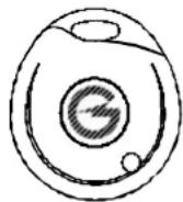
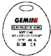
Art. 6108E
natural_image
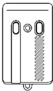
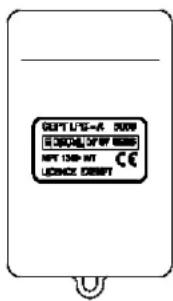
Simple line drawing of a rectangular device with two vertical ports and a hatched side panel (no text or symbols)Art. 5009E
The manufacturer declines every responsibility for any possible defect or failure to the device and to the vehicle's electric system due to incorrect installation or to the alteration of the indicated Technical Features. The alarm system has only a dissuasive function against possible thefts.
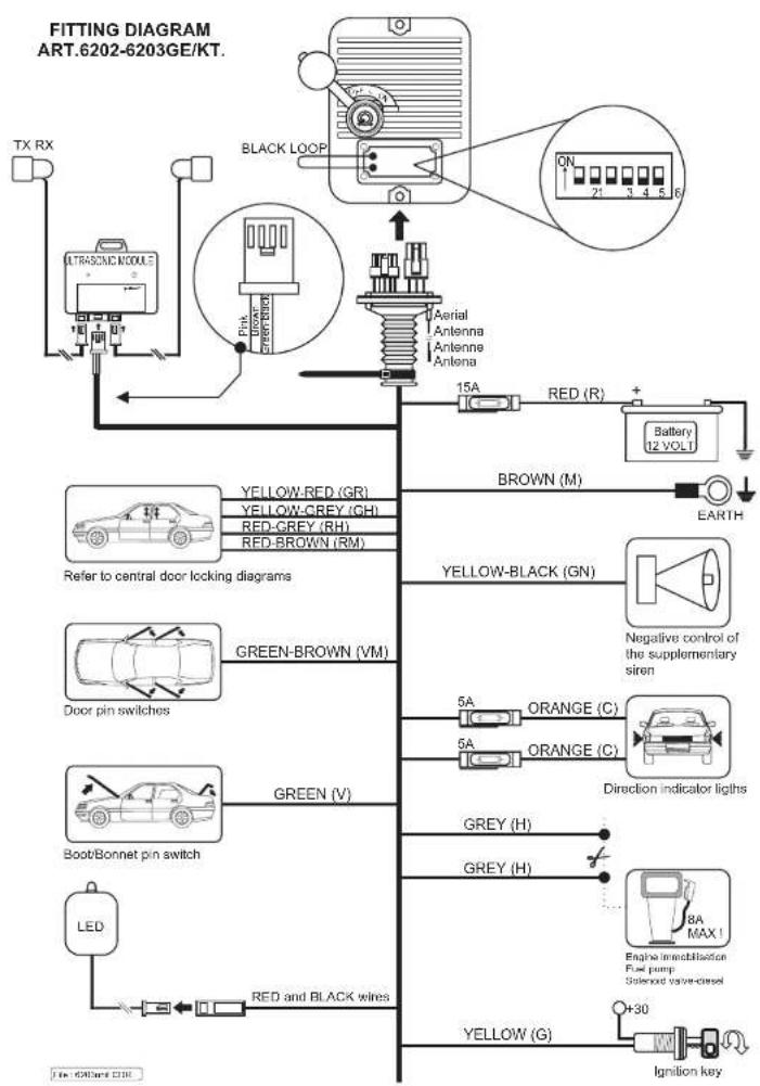
flowchart
graph TD
    A["TX RX"] --> B["ALTRASCENE MODULE"]
    B --> C["Black Loop"]
    C --> D["Aerial Antenna Antenna Antenna"]
    D --> E["15A"]
    E --> F["Battery 12 VOLT"]
    F --> G["BROWN (M)"]
    G --> H["EARTH"]
    I["Refer to central door locking diagrams"] --> J["YELLOW-RED (GR)"]
    I --> K["YELLOW-CREY (GH)"]
    I --> L["RED-CREY (RH)"]
    I --> M["RED-BROWN (RM)"]
    N["Door pin switches"] --> O["GREEN-BROWN (VM)"]
    P["Boot/Bonnet pin switch"] --> Q["GREEN (V)"]
    R["LED"] --> S["RED and BLACK wires"]
    T["Yellow-Black (GN)"] --> U["Negative control of the supplementary siren"]
    V["Orange (C)"] --> W["Direction indicator lights"]
    X["GREY (H)"] --> Y["8A MAX! Engine immobilisation Fuel pump Solvond valve-ciesel"]
    Z["YELLOW (G)"] --> AA["Ignition key"]
    AB["Ground"] --> AC["+30"]
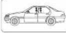 | Commande formotures centralisós.Eingang zentralvarmagelung.Manco oorro centralizaco.Camando fechas centralizadas.Contraio portervegrøndeling. |  | Sirono supplémentaire.Hupe oder sirene ohne skku.Sirona optiona.Sirene adicional.Elektronosone sirone. |
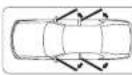 | Poussoir portes.Eingang tirkontaktischalter.Entrada puertas.Entrada portas.Deurcontacten. |  | Indicataure de directions.Blinker.Intermiontes.Luzes de direcção.Knipporionten. |
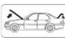 | Poussoir oetro ot capot.Eingang haubenkontaide.Entrada capó y malaton.Entrada vão motor e bagageira.Motorkap/Kofforoksol contacten. |  | Entrée captoir.Sensoroneingang.Entrada sensoros.Entrada sensoros.Sensorongang. |
 | autoseimentöre.rene.autoseimentada.autoseimentada,roomairons. |  | près contact.Zündung.Positivo bajo lave.Postivo de chave.Contactact. |
 | re motourrechnung der stromversorgung derripumpere-ción circuito eléctrico bloqueo motor.gm circuito eléctrico bloqueo motoriderbreking. |  | 108E Art 500E |
| UK I F | D E | P | N | |||
| Red | Rosso | Rouge | Rojo | Vormelho | Rot | Rood |
| Brown | Marone | Marron | Marron | Marron | Braun | Bruin |
| Grey | Grigio | Gris | Gris | Cinza | Grau | Grijs |
| Green | Verde | Vert | Verde | Verde | Grün | Gruen |
| Green-Brown | Verde-Marrone | Verl-Marron | Verde-Marron | Verde-Marron | Grün-Braun | Green-Bruin |
| Green-Black | Verde-Nero | Vert-Noir | Verde-Negro | Verde-Prelo | Grün-Schwarz | Green-Zwart |
| Yellow | Giallo | Jaune | Amarillo | Amarilo | Gelb | Geel |
| Pink | Rosa | Roso | Rosa | Rosa | Rosa | Rozo |
| Yellow-Red | Giallo-Rosso | Jaune-Rouge | Amarillo-Rojo | Amarino-Varmelho | Gelb-Rot | Geel-Rood |
| Yellow-Grey | Giallo-Grigio | Jaune-Gris | Amarillo-Gris | Amaralo-Cinza | Gelb-Grau | Geel-Grija |
| Red-Grey | Rosso-Grigio | Rougo-Gris | Rojo-Gris | Vormelho-Cinza | Rot-Grau | Rood-Grijs |
| Red-Brown | Rosso-Marrone | Rouge-Marron | Rojo-Marron | Vormelho-Marron | Rot-Braun | Rood-Bruin |
| White | Blanco | Blanc | Blanco | Branco | Weiss | Wit |
| I | GB | F | D | E | P | NL | |
| GR | GIALLO-ROSSO | YELLOWRED | JAUNE-ROUGE | CELB-BLAU | AMARILLO-AZUL | AMARELLO-AZUL | CEEL-BLAUY |
| GH | GIALLO GRISSIO | YELLOW GREY | JAUNE-GRIS | GELD-GRAU | AMARILLO-GRIS | AMARELLO-GRISA | GEEL-GRUS |
| RH | ROSSO-GRISIO | RED-SNLY | ROUGE-GRIS | ROT-GRAU | ROJO-GRIS | VERMELHO-GRISA | ROOO-GRUS |
| RM | ROSSO-MARRONE | RED-BROWN | ROUGE-MARRON | ROT-BRAIN | ROJO-MARRONA | VERMELHO-MARRON | ROOO-BRAIN |
| S | ROSA | PINK | ROSE | ROSA | ROSA | ROSA | ROZE |
| RL | ROSSO-BLU | RED BLUE | ROUGE-BLUE | ROT-BLAU | ROJO-AZUL | VERMELHO-AZUL | ROOO-BLAUY |
| BN | BIANCO-NERO | WHITE-BLACK | BLAND-NOR | WESSE-SCHWARZ | BLANCO-NECRO | BRANCO-PRETO | WIT-ZWART |
| R | ROSSO | RED | ROUGE | ROT | ROJO | VERMELHO | ROOD |
| L | BLU | BLUE | BLUE | BLAU | AZUL | AZUL | BLAUY |
flowchart
graph TD
    A["Compressor"] --> B["Yellow-RED (GR)"]
    A --> C["Yellow-GREY (GH)"]
    A --> D["RED-GREY (RH)"]
    A --> E["RED-BROWN (RM)"]
    B --> F["GE 2352"]
    C --> F
    D --> F
    E --> F
    F --> G["GE 2352"]
    G --> H["Original Motor"]
    I["ON 1.5 sec. 5 OFF"] --> J["Yellow-RED (GR)"]
    I --> K["Yellow-GREY (GH)"]
    I --> L["RED-GREY (RH)"]
    I --> M["RED-BROWN (RM)"]
    N["30-30"] --> O["GE 2352"]
    P["87"] --> Q["K1"]
    R["87a"] --> S["K2"]
    T["30"] --> U["87"]
    V["n.c."] --> W["ACU 80"]
Brand : GEMINI
Model : 6202
Category : Car alarm