WBS-200N - Access Point Planet - Free user manual and instructions
Find the device manual for free WBS-200N Planet in PDF.


| Product Type | Outdoor Wireless Access Point / CPE |
| Model | WBS-200N |
| Wireless Standard | IEEE 802.11b/g/n |
| Data Rate | Up to 300Mbps (2T2R) |
| Frequency Band | 2.412 - 2.472 GHz |
| Antenna | Built-in 8dBi dual-polarization directional antenna |
| Interfaces | 1 x 10/100BASE-TX PoE LAN (LAN1), 1 x 10/100BASE-TX LAN (LAN2) |
| Power Supply | Passive PoE (24V DC, 0.6A) via LAN1 |
| Power Consumption | Max 7.2W |
| Dimensions (W x D x H) | 100 x 29 x 186 mm |
| Weight | 300 g |
| Enclosure Rating | IP55 (outdoor UV-resistant) |
| Operating Temperature | -20 to 70°C |
| Operation Modes | Access Point, Client Bridge, WDS (AP/Bridge/Station), Client Router (WISP), Repeater |
| Security | 64/128/152-bit WEP, WPA/WPA2, WPA-PSK/WPA2-PSK, 802.1X RADIUS |
| Maximum SSIDs | 4 (with VLAN mapping) |
| Maximum Wireless Clients | 64 (suggested 32) |
| LED Indicators | Power, LAN, WLAN, Signal Strength (in client modes) |
| Mounting | Pole or wall mount (bracket included) |
| Regulatory Certifications | CE, FCC, RoHS |
Frequently Asked Questions - WBS-200N Planet
User questions about WBS-200N Planet
0 question about this device. Answer the ones you know or ask your own.
Ask a new question about this device
Download the instructions for your Access Point in PDF format for free! Find your manual WBS-200N - Planet and take your electronic device back in hand. On this page are published all the documents necessary for the use of your device. WBS-200N by Planet.
USER MANUAL WBS-200N Planet
300Mbps 802.11n Outdoor Wireless AP/CPE
WAP-200N/WBS-200N

natural_image
Woman in business attire using a laptop on stairs (no visible text or symbols)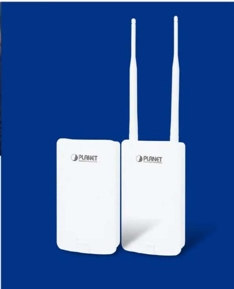
natural_image
Two white Planet wireless devices with two antennas against a solid blue background (no text or symbols visible on the devices themselves)Copyright
Copyright © 2017 by PLANET Technology Corp. All rights reserved. No part of this publication may be reproduced, transmitted, transcribed, stored in a retrieval system, or translated into any language or computer language, in any form or by any means, electronic, mechanical, magnetic, optical, chemical, manual or otherwise, without the prior written permission of PLANET.
PLANET makes no representations or warranties, either expressed or implied, with respect to the contents hereof and specifically disclaims any warranties, merchantability or fitness for any particular purpose. Any software described in this manual is sold or licensed "as is". Should the programs prove defective following their purchase, the buyer (and not this company, its distributor, or its dealer) assumes the entire cost of all necessary servicing, repair, and any incidental or consequential damages resulting from any defect in the software. Further, this company reserves the right to revise this publication and to make changes from time to time in the contents hereof without obligation to notify any person of such revision or changes.
All brand and product names mentioned in this manual are trademarks and/or registered trademarks of their respective holders.
FCC Interference Statement
This equipment has been tested and found to comply with the limits for a Class B digital device,
FCC pursuant to Part 15 of FCC Rules. These limits are designed to provide reasonable protection against harmful interference in a residential installation. This equipment generates, uses, and can radiate radio frequency energy and, if not installed and used in accordance with the instructions, may cause harmful interference to radio communications. However, there is no guarantee that interference will not occur in a particular installation. If this equipment does cause harmful interference to radio or television reception, which can be determined by turning the equipment off and on, the user is encouraged to try to correct the interference by one or more of the following measures:
- Reorient or relocate the receiving antenna.
- Increase the separation between the equipment and receiver.
- Connect the equipment into an outlet on a circuit different from that to which the receiver is connected.
- Consult the dealer or an experienced radio/TV technician for help.
FCC Caution:
Any changes or modifications not expressly approved by the party responsible for compliance could void the user's authority to operate the equipment. This transmitter must not be co-located or operating in conjunction with any other antenna or transmitter. To assure continued compliance, for example, use only shielded interface cables when connecting to computer or peripheral devices.
This device complies with Part 15 of the FCC Rules. Operation is subject to the following two conditions:
(1) This device may not cause harmful interference
(2) This device must accept any interference received, including interference that may cause undesired operation.
This transmitter must not be co-located or operating in conjunction with any other antenna or transmitter.
FCC Radiation Exposure Statement
This equipment complies with FCC radiation exposure limits set forth for an uncontrolled environment. This equipment should be installed and operated with a minimum distance of 21cm between the radiator and your body.
CE Compliance Statement
This device meets the RED directive 2014/53/EU of EU requirements on the limitation of exposure of the general public to electromagnetic fields by way of health protection. The device complies with RF specifications in that the distance between the device and your body should not be less than 20 cm.
Safety
This equipment is designed with the utmost care for the safety of those who install and use it. However, special attention must be paid to the dangers of electric shock and static electricity when working with electrical equipment. All guidelines must be followed at all times to ensure the safe use of the equipment.
WEEE regulation
To avoid the potential effects on the environment and human health as a result of the presence of hazardous substances in electrical and electronic equipment, end users of electrical and electronic equipment should understand the meaning of the crossed-out wheeled bin symbol. Do not dispose of WEEE as unsorted municipal waste; WEEE should be collected separately.
Revision
User Manual of PLANET 2.4GHz 300Mbps 802.11n Outdoor Wireless AP/CPE
Model: WAP-200N/WBS-200N
Rev: 1.0 (August, 2017)
Part No. EM-WAP-200N_WBS-200N_v1.0
CONTENTS
Chapter 1.Product Introduction....7
1.1 Package Contents....7
1.2 Product Description....8
1.3 Product Features....10
1.4 Product Specifications .... 11
Chapter 2.Hardware Installation....14
2.1 Hardware Description....14
2.1.1 The Bottom Panel 16
Chapter 3. Connecting to the AP .... 18
3.1 Preparation before Installation 18
3.1.1 Professional Installation Required 18
3.1.2 Safety Precautions....18
3.2 Installation Precautions....18
3.3 Installing the AP 20
Chapter 4. Quick Installation Guide ...... 22
4.1 Manual Network Setup -- TCP/IP Configuration....22
4.1.1 Configuring the IP Address Manually 22
4.2 Starting Setup in the Web UI....25
Chapter 5.Configuring the AP....27
5.1 Operation Mode....27
5.1.1 Access Point (AP)....29
5.1.2 Client Bridge (CB)....30
5.1.3 WDS Access Point (WDS AP) 31
5.1.4 WDS Station (WDS STA)....32
5.1.5 WDS Bridge (WDS PtP/WDS PtMP) 33
5.1.6 Client Router (CR/WISP) 39
5.1.7 Repeater 45
5.2 Status....49
5.2.1 Main 49
5.2.2 Save/Reload 51
5.2.3 Wireless Client List....52
5.2.4 WDS Link List 53
5.2.5 DHCP Client Table....53
5.2.6 Connection Status....54
5.2.7 System Log....55
5.3 System....56
5.3.1 IP Settings....56
5.3.2 Spanning Tree Settings (STP) 57
5.4 Router (WISP Mode Only)....58
5.4.1 DHCP Server Settings....58
5.4.2 WAN Settings....59
5.4.2.1. DHCP 60
5.4.2.2. Static IP 61
5.4.2.3. PPPoE 63
5.4.2.4. PPTP 64
5.4.3 VPN Pass Through 65
5.4.4 Port Forwarding 66
5.4.5 DMZ Settings 67
5.5 Wireless....68
5.5.1 Wireless Network....68
5.5.2 WDS Link Settings....71
5.5.3 Security Settings....73
5.5.4 Wireless MAC Filter 83
5.5.5 Wireless Advanced Settings 84
5.6 Management 85
5.6.1 Administration (Password Settings)......85
5.6.2 Management VLAN 86
5.6.3 SNMP Settings 87
5.6.4 Backup/Restore Settings 88
5.6.5 Auto Reboot Settings....89
5.6.6 Firmware Upgrade 89
5.6.7 Time Settings....91
5.6.8 Wi-Fi Schedule 92
5.6.9 CLI Settings 93
5.6.10 Log....93
5.6.11 Diagnostics 94
5.6.12 Logout....95
Appendix A: Troubleshooting....96
Appendix B: Use Planet Smart Discovery to find AP 98
Appendix C: FAQ....99
Q1: How to set up the AP Client Connection....99
Q2: How to set up the WDS Connection 108
FIGURES
FIGURE 2-1 THREE-WAY VIEW (WAP-200N)....14
FIGURE 2-2 THREE-WAY VIEW (WBS-200N)....14
FIGURE 2-3 REAR PANEL (WAP-200N)....15
FIGURE 2-4 REAR PANEL (WBS-200N)....15
FIGURE 2-5 BOTTOM PANEL (WAP-200N/WBS-200N)....17
FIGURE 2-6 POE WARNING LABEL ....17
FIGURE 3-1 POE AND LAN PORT CONNECTION....20
FIGURE 3-2 FINISH INSTALLATION AND CONNECT TO ANTENNAS (WAP-200N ONLY)....20
FIGURE 3-3 POLE MOUNTING....21
FIGURE 3-4 WALL MOUNTING....21
FIGURE 4-1 TCP/IP SETTING....23
FIGURE 4-2 WINDOWS START MENU ....24
FIGURE 4-3 SUCCESSFUL RESULT OF PING COMMAND 24
FIGURE 4-4 FAILED RESULT OF PING COMMAND....25
FIGURE 4-5 LOGIN BY DEFAULT IP ADDRESS....25
FIGURE 4-6 LOGIN WINDOW ....25
FIGURE 4-7 WEB UI SCREENSHOT....26
FIGURE 5-1 OPERATION MODE - ALL....28
FIGURE 5-2 OPERATION MODE - AP....29
FIGURE 5-3 OPERATION MODE - CLIENT BRIDGE....30
FIGURE 5-4 OPERATION MODE – WDS AP ...... 31
FIGURE 5-5 OPERATION MODE – WDS STATION....32
FIGURE 5-6 OPERATION MODE – WDS BRIDGE....33
FIGURE 5-7 OPERATION MODE - CLIENT ROUTER (WISP)....39
FIGURE 5-8 OPERATION MODE – REPEATER ....45
FIGURE 5-9 SYSTEM MENU - RESET 49
FIGURE 5-10 SYSTEM MENU – LANGUAGE OPTION ...... 49
FIGURE 5-11 MAIN STATUS....50
FIGURE 5-12 SAVE/RELOAD .... 51
FIGURE 5-13 SAVE/RELOAD - DEFAULT ....52
FIGURE 5-14 WIRELESS CLIENT LIST ....52
FIGURE 5-15 KICK THE CLIENT....52
FIGURE 5-16 WDS LINK STATUS....53
FIGURE 5-17 DHCP CLIENT LIST ....53
FIGURE 5-18 CONNECTION STATUS ....54
FIGURE 5-19 SYSTEM LOG ....55
FIGURE 5-20 LAN IP SETTINGS....56
FIGURE 5-21 SPANNING TREE SETTINGS....57
FIGURE 5-22 DHCP SERVER SETTINGS ....58
FIGURE 5-23 WAN SETTINGS – ALL....59
FIGURE 5-24 WAN SETTINGS – DHCP....61
FIGURE 5-25 WAN SETTINGS – STATIC IP 62
FIGURE 5-26 WAN SETTINGS – PPPOE....63
FIGURE 5-27 WAN SETTINGS – PPTP 64
FIGURE 5-28 VPN PASS THROUGH....65
FIGURE 5-29 PORT FORWARDING....66
FIGURE 5-30 PORT FORWARDING....67
FIGURE 5-31 DMZ 68
FIGURE 5-32 WIRELESS NETWORK – AP/WDS AP MODE ....69
FIGURE 5-33 WIRELESS NETWORK – SSID PROFILE....69
FIGURE 5-34 WIRELESS NETWORK – CB/WDS STA/CR/REPEATER MODE ....71
FIGURE 5-35 WDS LINK SETTINGS – WDS BRIDGE MODE 72
FIGURE 5-36 SECURITY SETTINGS – AP/WDS AP MODE ....73
FIGURE 5-37 SECURITY SETTINGS – CB/WDS STA/CR/REPEATER MODE....73
FIGURE 5-38 SECURITY SETTINGS – WDS BRIDGE MODE....74
FIGURE 5-39 SECURITY SETTINGS – WEP 75
FIGURE 5-40 SECURITY SETTINGS – WPA-PSK....76
FIGURE 5-41 SECURITY SETTINGS – WPA2-PSK....77
FIGURE 5-42 SECURITY SETTINGS – WPA-PSK MIXED....77
FIGURE 5-43 SECURITY SETTINGS – WPA (WPA ENTERPRISE)....78
FIGURE 5-44 SECURITY SETTINGS – WPA2 (WPA2 ENTERPRISE) 79
FIGURE 5-45 SECURITY SETTINGS – WPA MIXED (WPA MIXED ENTERPRISE)....81
FIGURE 5-46 WIRELESS MAC FILTER ....83
FIGURE 5-47 WIRELESS ADVANCED SETTINGS ....84
FIGURE 5-48 ADMINISTRATION (PASSWORD SETTINGS)....86
FIGURE 5-49 MANAGEMENT VLAN....86
FIGURE 5-50 SNMP SETTINGS ....87
FIGURE 5-51 BACKUP/RESTORE SETTINGS....88
FIGURE 5-52 AUTO REBOOT SETTINGS....89
FIGURE 5-53 FIRMWARE UPGRADE....89
FIGURE 5-54 TIME SETTINGS....91
FIGURE 5-55 WI-FI SCHEDULE....92
FIGURE 5-56 CLI SETTINGS....93
FIGURE 5-57 LOG....93
FIGURE 5-58 DIAGNOSTICS....94
FIGURE 5-59 LOGOUT....95
Chapter 1. Product Introduction
1.1 Package Contents
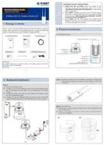
Thank you for choosing PLANET WAP-200N/WBS-200N series. Before installing the AP/CPE, please verify the contents inside the package box.
WBS-200N / WAP-200N

Quick Installation Guide
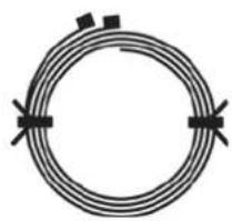
Mounting Strap x 2
natural_image
Simple circular diagram with two black arrows pointing inward, no text or symbols present.Screw Set x 1

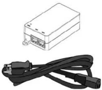
PoE Injector & Power Cord
natural_image
Illustration of a rectangular device with internal ports and a black cable with two connectors (no text or symbols)Antenna x 2 (WAP-200N only)


If there is any item missing or damaged, please contact the seller immediately.
1.2 Product Description
Cost-effective Wireless Solution with Superior Performance
PLANET WAP-200N/WBS-200N 300Mbps 802.11n Outdoor Wireless AP/CPE offers a better range and excellent throughput. Via the WAP-200N's RP-SMA antenna connectors and the WBS-200N's embedded 8dBi dual-polarity directional antenna, it is easy to build different point to multi-point applications with good diversity coverage and better noise immunity effect, thus heightening the performance and stability of a long-distance connectivity.
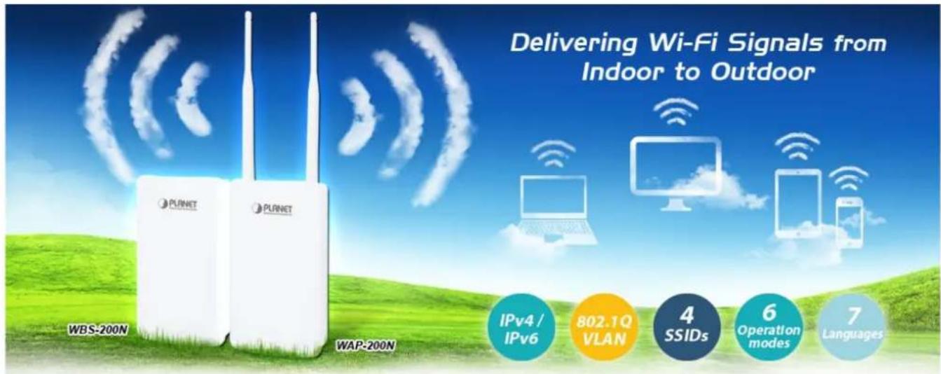
Designed for Various Requirements
The WAP-200N/WBS-200N is dedicatedly designed for WISP solution that provides CPE users with Internet access via the WISP provider in rural areas. Besides, it caters to various wireless communication connectivities (AP, Client, WDS, Repeater and WISP), thus meeting users' application requirements.
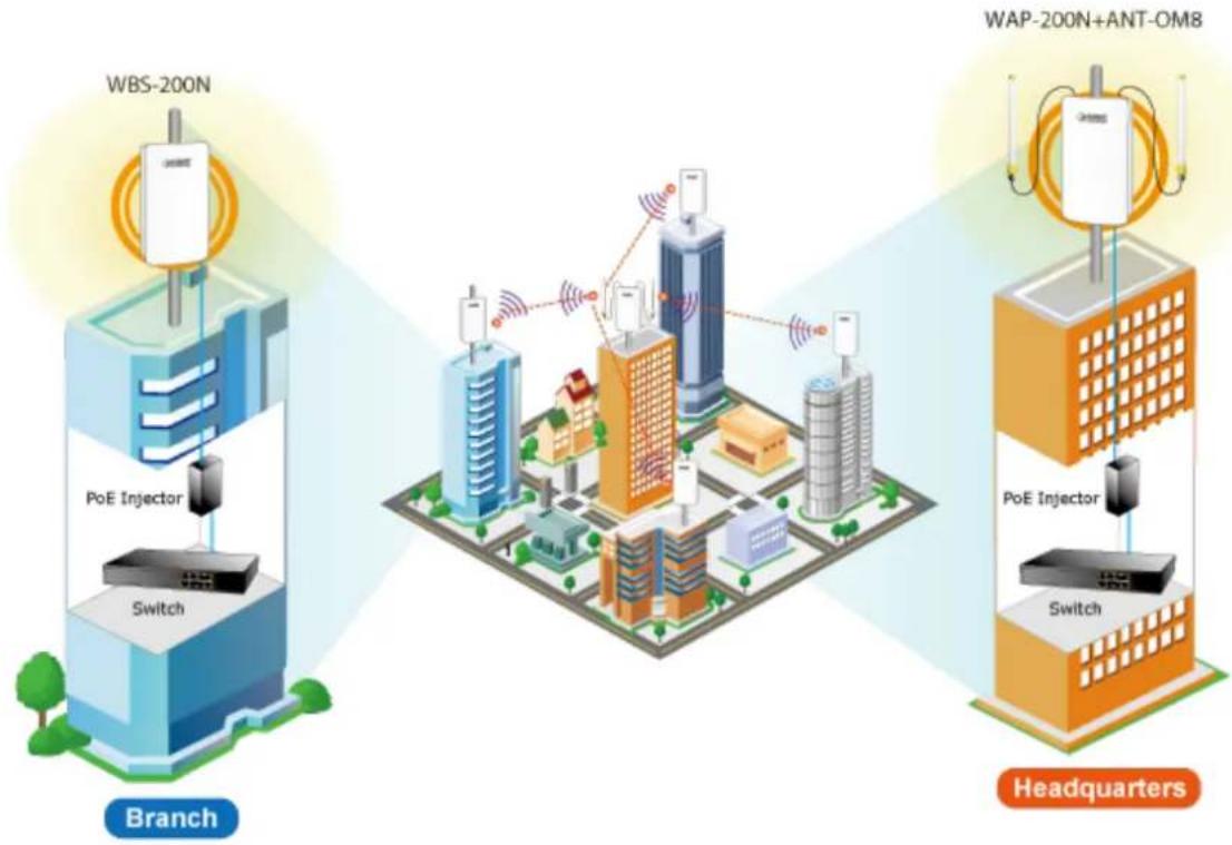
flowchart
graph TD
    subgraph Branch
        A["WBS-200N"] --> B["Switch"]
        C["PoE Injector"] --> D["Branch"]
        E["Switch"] --> F["Branch"]
    end
    subgraph Headquarters
        G["WAP-200N+ANT-OM8"] --> H["Switch"]
        I["PoE Injector"] --> J["Branch"]
        K["Switch"] --> L["Headquarters"]
    end
    A --> C
    C --> E
    E --> G
    G --> I
    style Branch fill:#f9f,stroke:#333
    style Headquarters fill:#bbf,stroke:#333
Multiple SSIDs with VLAN Tagging
Multiple SSIDs can broadcast up to four wireless networks with different names. For management purposes, the IEEE 802.1Q VLAN supported allows multiple VLAN tags to be mapped to multiple SSIDs to distinguish the wireless access. This makes it possible for the WAP-200N/WBS-200N to work with managed Ethernet switches to have VLANs assigned for a different access level and authority.
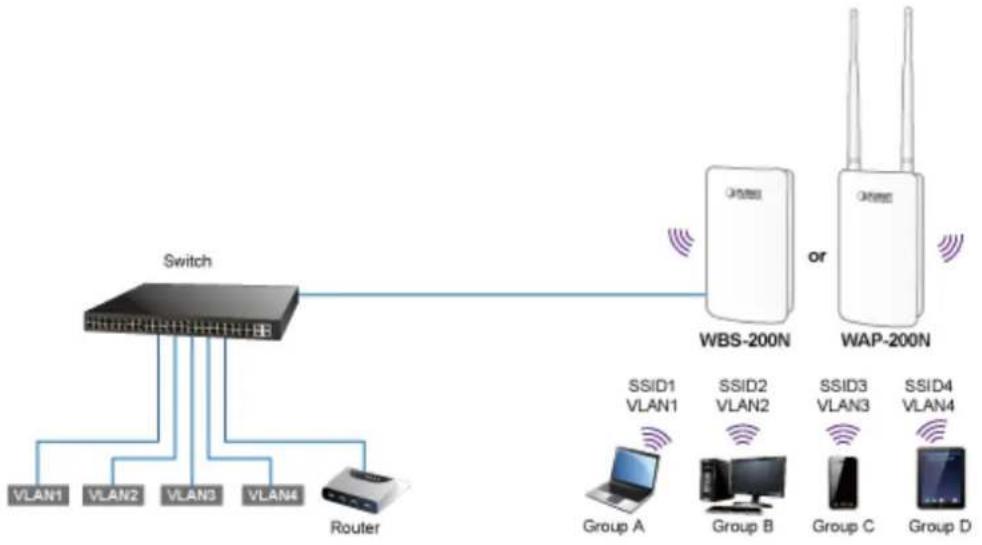
flowchart
graph TD
    A["Switch"] --> B["WBS-200N"]
    A --> C["WAP-200N"]
    B --> D["Group A"]
    B --> E["Group B"]
    B --> F["Group C"]
    B --> G["Group D"]
    H["VLAN1"] --> A
    I["VLAN2"] --> A
    J["VLAN3"] --> A
    K["VLAN4"] --> A
    L["Router"] --> A
    style A fill:#f9f,stroke:#333
    style B fill:#ccf,stroke:#333
    style C fill:#ccf,stroke:#333
    style D fill:#dfd,stroke:#333
    style E fill:#dfd,stroke:#333
    style F fill:#dfd,stroke:#333
    style G fill:#dfd,stroke:#333
    style H fill:#dfd,stroke:#333
    style I fill:#dfd,stroke:#333
    style J fill:#dfd,stroke:#333
    style K fill:#dfd,stroke:#333
    style L fill:#dfd,stroke:#333
Flexible and Reliable Outdoor Characteristics
The WAP-200N/WBS-200N is definitely suitable for wireless IP surveillance to enable to have wide deployments between buildings and to act as the backbone of public service. Additionally, its self-healing capability keeps connection alive all the time. With the IP55-rated outdoor UV-resistant enclosure, the WAP-200N/WBS-200N can perform normally under rigorous weather conditions, meaning it can be installed in any harsh, outdoor environments. With the proprietary Power over Ethernet (PoE) design, the WAP-200N/WBS-200N can be easily installed in the areas where power outlets are not available.
Advanced Security and Rigorous Authentication
The WAP-200N/WBS-200N supports 152-bit WEP, WPA/WPA2, WPA-PSK and WPA2-PSK wireless encryptions, the advanced WPA2-AES mechanism and 802.1X RADIUS authentication, which can effectively prevent eavesdropping by unauthorized users or bandwidth occupied by unauthenticated wireless access. Furthermore, any users are granted or denied access to the wireless LAN network based on the ACL (Access Control List) that the administrator pre-established.
Easy Deployment and Management
With user-friendly Web UI and comprehensive management features including client limit control and wireless traffic shaping, the WAP-200N/WBS-200N is easy to limit the client access and inbound/outbound bandwidth control, even for users who have no experience in setting up a wireless network. Furthermore, with the Planet Smart Discovery Utility, SNMP and diagnostics tools, the WAP-200N/WBS-200N is convenient to be managed remotely.
1.3 Product Features
Industrial Compliant Wireless LAN
■ Compliant with the IEEE 802.11b/g/n wireless technology
■ 2T2R architecture with data rate of up to 300Mbps
■ Equipped with two 10/100Mbps RJ45 ports, with auto MDI/MDI-X supported
Fixed Network Broadband Router
■ Supported WAN connection types in WISP mode: DHCP, Static IP, PPPoE, PPTP
■ Supports Port Forwarding and DMZ for various networking applications
■ Supports DHCP server in WISP mode
RF Interface Characteristics
■ Built-in 5dBi detachable antennas with RP-SMA connectors (WAP-200N)
■ Built-in 8dBi dual-polarization antenna (WBS-200N)
■ High output power with multiply-adjustable transmit power control
Outdoor Environmental Characteristics
■ IP55 rating
■ Passive Power over Ethernet design
■ Operating temperature: -20\~70°C
Multiple Operation Modes and Wireless Features
■ Multiple operation modes: AP, Client Bridge, Client Router (WISP), WDS, Repeater
■ WMM (Wi-Fi multimedia) provides higher priority to multimedia transmitting over wireless
■ Wireless Traffic Shaping to control the upload/download bandwidth
■ Wi-Fi scheduler allows to be enabled or disabled based on predefined schedule
▶ Secure Network Connection
■ Full encryption supported: 64-/128-/152-bit WEP, WPA/WPA2, WPA-PSK/WPA2-PSK and 802.1X RADIUS authentication
■ Supports 802.1Q VLAN pass-through over WDS and SSID-to-VLAN mapping
■ Supports up to 50 entries of MAC address filtering
Easy Installation and Management
■ IPv4/IPv6 dual-stack management networks
■ Multilingual Web User Interface: English, Spanish, French, German, Portuguese, Russian, and Simplified Chinese
■ CLI command and SNMP-based management interface
■ Self-healing mechanism through system auto reboot setting
■ System status monitoring through remote Syslog Server and Device Discovery
■ Diagnostic tools include Ping, Traceroute, Speed
■ Planet Smart Discovery Utility allows administrator to discover and locate each AP
1.4 Product Specifications
| Product | WAP-200N | WBS-200N |
| 2.4GHz 300Mbps 802.11n Outdoor Wireless AP/CPE | ||
| Hardware Features | ||
| Standard Support | IEEE802.11b/g/nIEEE 802.3IEEE 802.3uIEEE 802.3x | |
| Memory | 64 Mbytes DDR SDRAM16 Mbytes Flash | |
| PoE | Passive PoE | |
| Interface | Wireless IEEE 802.11b/g/n, 2T2RPoE LAN (LAN 1): 1 x 10/100BASE-TX, auto-MDI/MDIX, 24V passive PoE In LAN 2: 1 x 10/100BASE-TX, auto-MDI/MDIX | |
| Button | Reset button | |
| LED | PWR, LAN, WLAN, Signal Strength | |
| Dimensions (W x D x H) | 100 x 29 x 186mm (without antennas)100 x 29 x 380mm (with antennas) | 100 x 29 x 186mm |
| Weight | 300g (without antennas)332g (with antennas) | 300g |
| Power Consumption | Maximum 7.2W | |
| Power Requirements | LAN1■ 24V DC, 0.6A (Passive PoE)■ Pin 4, 5 V DC+■ Pin 7, 8 V DC- | |
| Mounting Type | Mast, wall mount | |
| Wireless Interface Specifications | ||
| Antenna | Built-in 5dBi detachable omnidirectional antennas with RP-SMA connectorsHPBW Horizontal: 360 degreesHPBW Vertical: 30 degrees | Built-in 8dBi directional antenna with dual polarization[Port1]HPBW Horizontal: 78 degreesHPBW Vertical: 45 degrees[Port2]HPBW Horizontal: 54 degreesHPBW Vertical: 59 degrees |
| Data Rate | IEEE 802.11b: 1, 2, 5.5, 11MbpsIEEE 802.11g: up to 54MbpsIEEE 802.11n (20MHz): up to 150MbpsIEEE 802.11n (40MHz): up to 300Mbps | |
| Media Access Control | CSMA/CA | |
| Modulation | Transmission/Emission type: OFDMData Modulation type: OFDM with BPSK, QPSK, 16-QAM, 64-QAM | |
| Frequency Band | 2.412GHz ~ 2.472GHz | |
| Operating Channel | United States -- FCC: 2.414~2.462GHz (11 channels)Europe -- ETSI: 2.412~2.472GHz (13 channels) | |
| RF Output Power (dBm) | FCC: IEEE 802.11b/g/n: up to 26 ± 2dBmETSI: IEEE 802.11b/g/n: < 20dBm (EIRP) | |
| Receiver Sensitivity (dBm) | IEEE 802.11b:-95/-93dBm (1~2/ 5.5~11Mbps)IEEE 802.11g:-95/-93/-92/-80/-77/-75dBm (6/ 9~18/ 24/ 36/ 48/ 54Mbps)IEEE 802.11n:MCS0/ MCS8: -95dBmMCS1/ MCS9: -93dBmMCS2/ MCS10: -92dBmMCS3/ MCS11: -90dBmMCS4/ MCS12: -86dBmMCS5/ MCS13: -83dBmMCS6/ MCS14: -76dBmMCS7/ MCS15: -73dBm | |
| Environment & Certification | ||
| Operating Temperature | -20~70 degrees C | |
| Operating Humidity | 10~90% (non-condensing) | |
| IP Level | IP55 | |
| Regulatory | CE, FCC, RoHS | |
| Software Features | ||
| LAN | ■ Static IP■ Dynamic IP■ DHCP server in WISP mode | |
| Supports 802.1d STP (Spanning Tree) | ||
| WAN Connection Type (WISP Mode only) | ■ Static IP■ Dynamic IP■ PPPoE■ PPTP | |
| Wireless Modes | ■ Access Point■ Client Bridge■ WDS (AP/Bridge/Station)■ Client Router (WISP)/Client AP Router (WISP+AP)■ Repeater | |
| Firewall | Offers DoS protection to guard user's content network against DoS attacks | |
| Built-in DMZ and Port Forwarding | ||
| VPN Pass-through:■ PPTP Pass-through■ L2TP Pass-through■ IPSec Pass-through | ||
| Channel Width | 20MHz/40MHz | |
| Encryption Type | 64-/128-/152-bit WEP, WPA, WPA-PSK, WPA2, WPA2-PSK, 802.1X | |
| Wireless Security | Enable/Disable SSID Broadcast | |
| Wireless MAC address filtering up to 50 entries | ||
| VAP Separation, Station Separation | ||
| Max. Wireless Clients | Max. 64 (Suggested 32, depending on usage) | |
| Max. SSIDs | Up to 4 | |
| Max. WDS Peers | Up to 4 | |
| Wireless QoS | Supports Wi-Fi Multimedia (WMM) | |
| Supports Wireless Traffic Shaping per Radio | ||
| Wireless Advanced Control | Auto Channel Selection | |
| Auto Transmit Power by Regular Domains | ||
| Client Limit Control | ||
| Distance Control (Auto Ack Timeout) | ||
| Wi-Fi Schedule | ||
| Status Monitoring | Connection Status | |
| Device Discovery, PLANET Smart Discovery | ||
| Wireless Client List/WDS Link List | ||
| DHCP Client Table | ||
| System Log supports remote syslog server | ||
| Signal Strength LEDs in Client Bridge and WDS Station modes | ||
| VLAN | VLAN pass-through over WDS | |
| SSID-to-VLAN mapping | ||
| Management VLAN (VID: 1~4094) | ||
| Self-healing | Supports auto reboot settings | |
| NTP | Network Time Management | |
| Management | Web-based UI, CLI (Command Line Interface) supported | |
| Configuration backup and restore | ||
| SNMP v1/v2c/v3 support, MIB I/II, Private MIB | ||
| Diagnostic Tools | Built-in Ping, Trace Route, Speed Test Tools | |
Chapter 2. Hardware Installation
2.1 Hardware Description
■ Dimensions (W x D x H): 100 x 29 x 186mm (without antennas)/100 x 29 x 380mm (with 5dBi antennas)
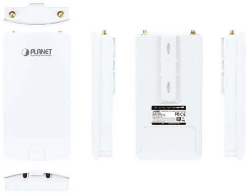
natural_image
Exterior view of a white Planet Wireless device with multiple side panels showing front, top, and side views (no readable text or symbols)Figure 2-1 Three-way View (WAP-200N)
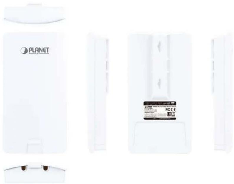
natural_image
Exterior view of a white Planet air purifier unit with visible branding and a small card (no text or symbols on main body)Figure 2-2 Three-way View (WBS-200N)
Rear Panel – LED
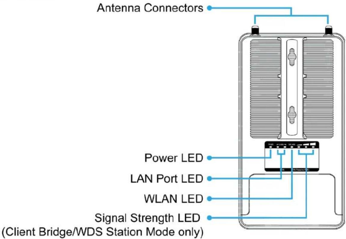
Figure 2-3 Rear Panel (WAP-200N)
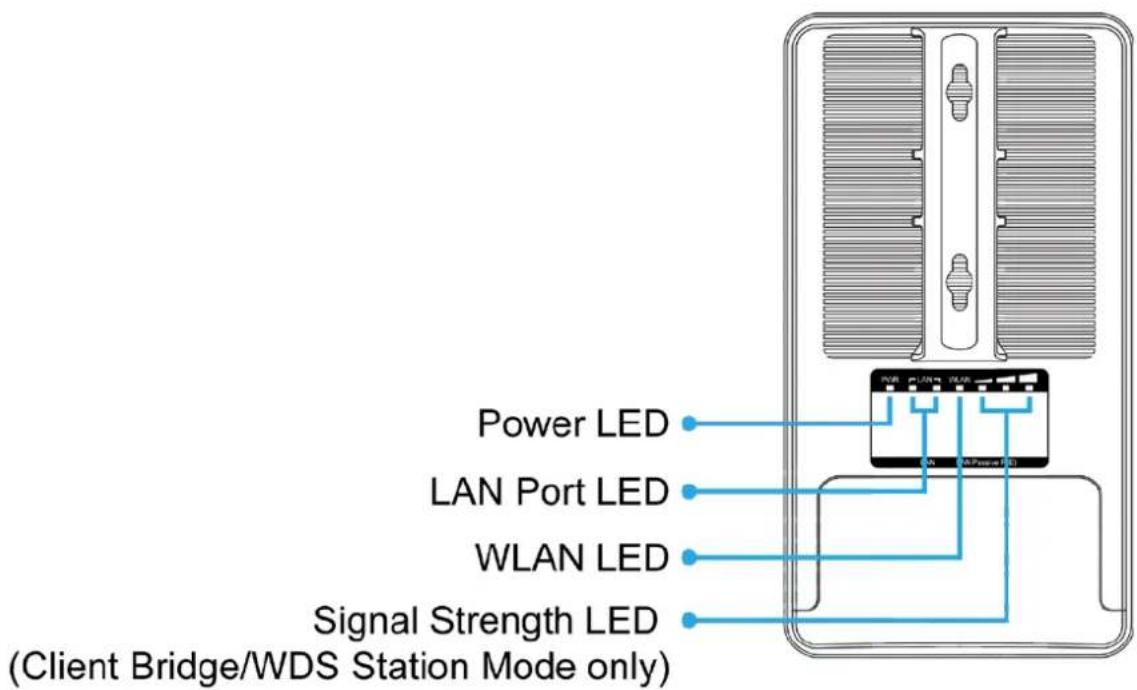
Figure 2-4 Rear Panel (WBS-200N)
LED Definition
| LED State Meaning | ||
| Power | On | The device is powered on |
| Off | The device is powered off | |
| LAN Ports | On Port linked | |
| Blinking | Data is transmitting or receiving data | |
| Off No link | ||
| WLAN | On | The wireless radio is on |
| Blinking | Data is transmitting or receiving over wireless | |
| Off | The wireless radio is off | |
| Signal Strength(Client Bridge/WDS Station/Client Router mode only) | Green LED on | Signal is good |
| Orange LED on | Signal is normal | |
| Red LED on | Signal is poor |
Table 2-1 The LED indication
2.1.1 The Bottom Panel
The Bottom panel provides the physical connectors connected to the power adapter and any other network device. Figure 2-5 shows the bottom panel of the WAP-200N/WBS-200N.
Bottom Panel
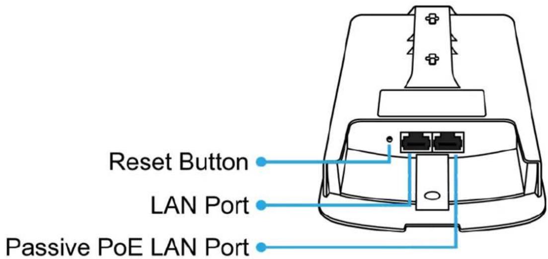
Figure 2-5 Bottom Panel (WAP-200N/WBS-200N)
PoE Warning Label

Figure 2-6 PoE Warning Label
Hardware Interface Definition
| Object Description | |
| Antenna Connectors(WAP-200N only) | 2 RP-SMA (Female) antenna connectors |
| Passive PoE LAN Port | 10/100Mbps RJ45 port, auto MDI/MDI-XPassive PoE/PD supported, 24V DC InPin assignment:Pins 4, 5 (+)Pins 7, 8 (-)NOTE: Please use the 24V DC Passive PoE only (included) |
| LAN Port | 10/100Mbps RJ45 port, auto MDI/MDI-X |
| Reset Button | Press and hold the Reset button on the device for over 10 seconds to return to the factory default setting. |
Table 2-2 Hardware Interface Definition
Chapter 3. Connecting to the AP
3.1 Preparation before Installation
3.1.1 Professional Installation Required
Please seek assistance from a professional installer who is well trained in the RF installation and knowledgeable in the local regulations.
3.1.2 Safety Precautions
- To keep you safe and install the hardware properly, please read and follow these safety precautions.
- If you are installing the WBS-200N or WAP-200N for the first time, for your safety as well as others', please seek assistance from a professional installer who has received safety training on the hazards involved.
- Keep safety as well as performance in mind when selecting your installation site, especially where there are electric power and phone lines.
- When installing the WBS-200N or WAP-200N, please note the following things:
♦ Do not use a metal ladder;
Do not work on a wet or windy day; -
Wear shoes with rubber soles and heels, rubber gloves, long sleeved shirt or jacket.
-
When the system is operational, avoid standing directly in front of it. Strong RF fields are present when the transmitter is on.
3.2 Installation Precautions
■ Users MUST use a proper and well-installed surge arrestor and grounding kit with WBS-200N or WAP-200N; otherwise, a random lightning could easily cause fatal damage to the WBS-200N or WAP-200N. EMD (Lightning) DAMAGE IS NOT COVERED UNDER WARRANTY.
- Users MUST use the “Power Cord and PoE Injector” shipped in the box with the WBS-200N or WAP-200N. Use of other options will cause damage to the WBS-200N or WAP-200N.

OUTDOOR INSTALLATION WARNING
IMPORTANT SAFETY PRECAUTIONS:
LIVES MAY BE AT RISK! Carefully observe these instructions and any special instructions that are included with the equipment you are installing.
CONTACTING POWER LINES CAN BE LETHAL. Make sure no power lines are anywhere where possible contact can be made. Antennas, masts, towers, guy wires or cables may lean or fall and contact these lines. People may be injured or killed if they are touching or holding any part of equipment when it contacts electric lines. Make sure that equipment or personnel do not come in contact directly or indirectly with power lines.
The horizontal distance from a tower, mast or antenna to the nearest power line should be at least twice the total length of the mast/antenna combination. This will ensure that the mast will not contact power if it falls either during installation or later.
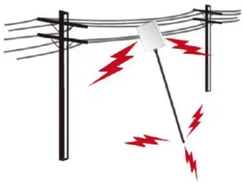
natural_image
Illustration of a utility pole with red lightning bolts indicating electric shock (no text or symbols)TO AVOID FALLING, USE SAFE PROCEDURES WHEN WORKING AT HEIGHTS ABOVE GROUND.
- Select equipment locations that will allow safe, simple equipment installation.
- Don't work alone. A friend or co-worker can save your life if an accident happens.
- Use approved non-conducting lasers and other safety equipment. Make sure all equipment is in good repair.
- If a tower or mast begins falling, don't attempt to catch it. Stand back and let it fall.
- If anything such as a wire or mast does come in contact with a power line, DON'T TOUCH IT OR ATTEMPT TO MOVE IT. Instead, save your life by calling the power company.
- Don't attempt to erect antennas or towers on windy days.
MAKE SURE ALL TOWERS AND MASTS ARE SECURELY GROUNDED, AND ELECTRICAL CABLES CONNECTED TO ANTENNAS HAVE LIGHTNING ARRESTORS. This will help prevent fire damage or human injury in case of lightning, static build-up, or short circuit within equipment connected to the antenna.
- The base of the antenna mast or tower must be connected directly to the building protective ground or to one or more approved grounding rods, using 1 OAWG ground wire and corrosion-resistant connectors.
- Refer to the National Electrical Code for grounding details.
IF A PERSON COMES IN CONTACT WITH ELECTRICAL POWER, AND CANNOT MOVE:
- DON'T TOUCH THAT PERSON, OR YOU MAY BE ELECTROCUTED.
- Use a non-conductive dry board, stick or rope to push or drag them so they no longer are in contact with electrical power.
Once they are no longer contacting electrical power, administer CPR if you are certified, and make sure that emergency medical aid has been requested.
3.3 Installing the AP
Please install the AP according to the following steps. Don't forget to pull out the power plug and keep your hands dry.
Step 1. PoE and LAN port connection:
(1) Remove the bottom cover.
(2) Connect one end of the Ethernet cable into the LAN (Passive PoE) port of the device and the other end to the PoE port on the PoE Injector.
(3) Connect the power cord with the PoE Injector and plug the other end into an electrical outlet.
(4) Connect the second Ethernet cable into the LAN port of the PoE Injector and the other end to the Ethernet port on the computer.
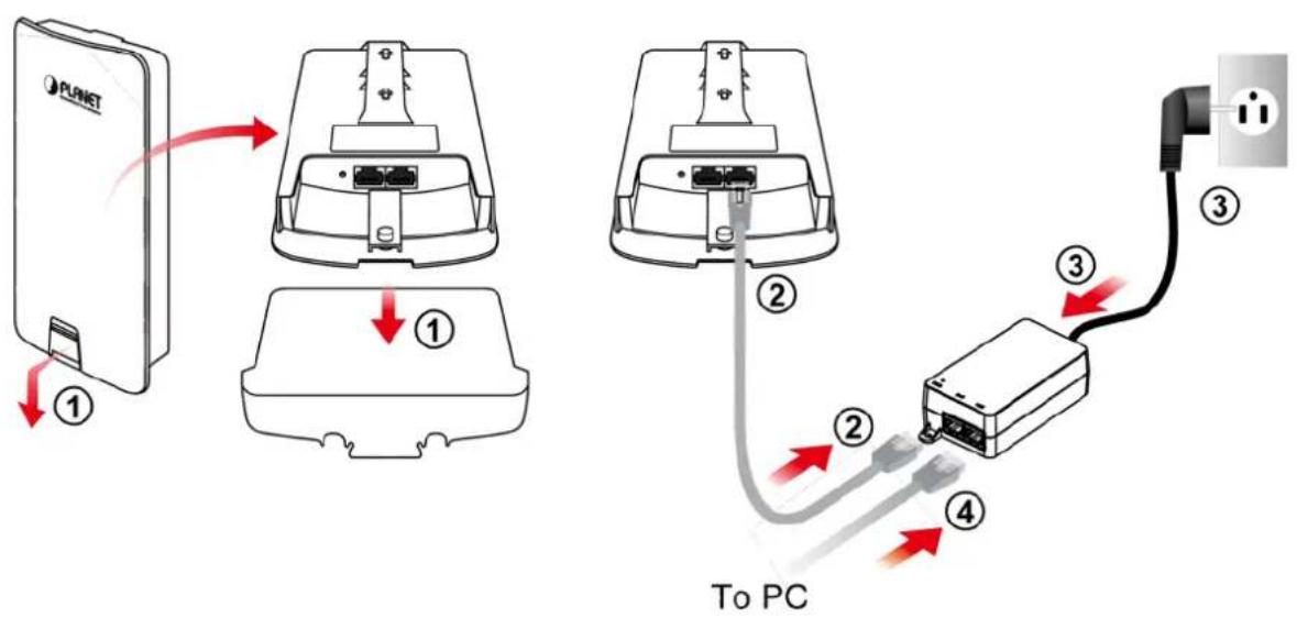
Figure 3-1 PoE and LAN port connection
Step 2. Attach the antennas onto the antenna connectors of the device and place the bottom cover back into the device to finish the installation.
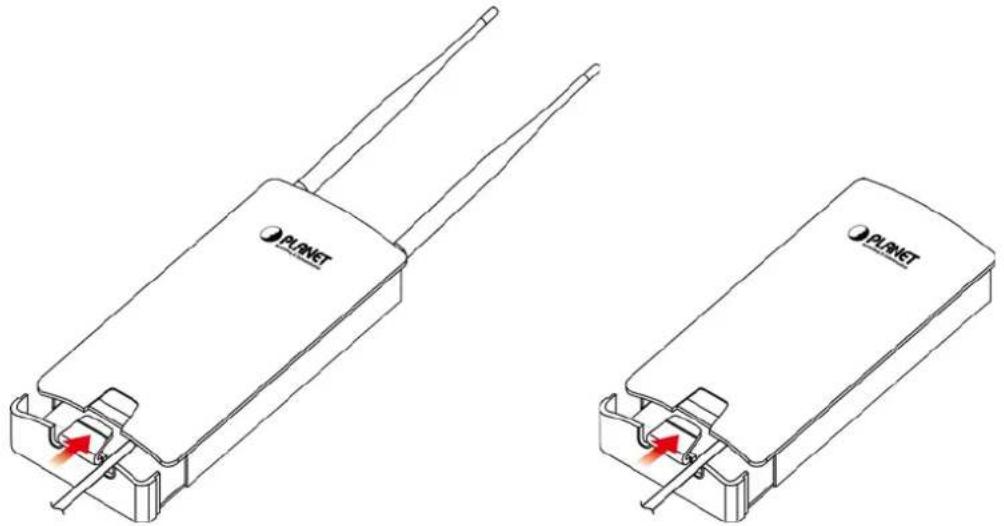
natural_image
Two identical PLNET device diagrams showing internal components with red arrows indicating ports (no text or symbols present)Figure 3-2 Finish installation and connect to antennas (WAP-200N only)
Step 3. Pole Mounting:
(1) Thread two mounting straps through the mounting bracket on the back of the device.
(2) Position the device on a pole and secure both mounting straps to finish the installation.
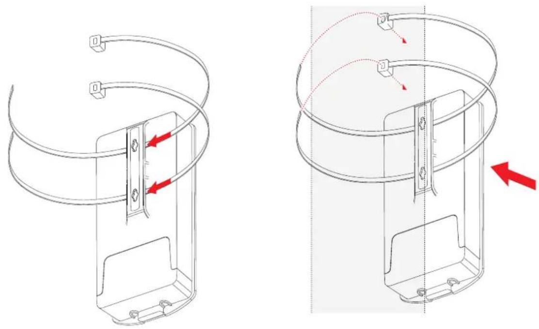
natural_image
Technical line drawing of a mechanical component with red arrows indicating assembly or movement (no text or symbols present)Figure 3-3 Pole Mounting
Step 4. Wall Mounting:
(1) Secure the adhesive label to a position on the wall where you would like to install the device.
(2) Follow the plotting sticker to drill two holes and secure the plastic anchors.
(3) Align the screw holes on the mounting bracket with the screws and then install the device on the wall to finish the installation.
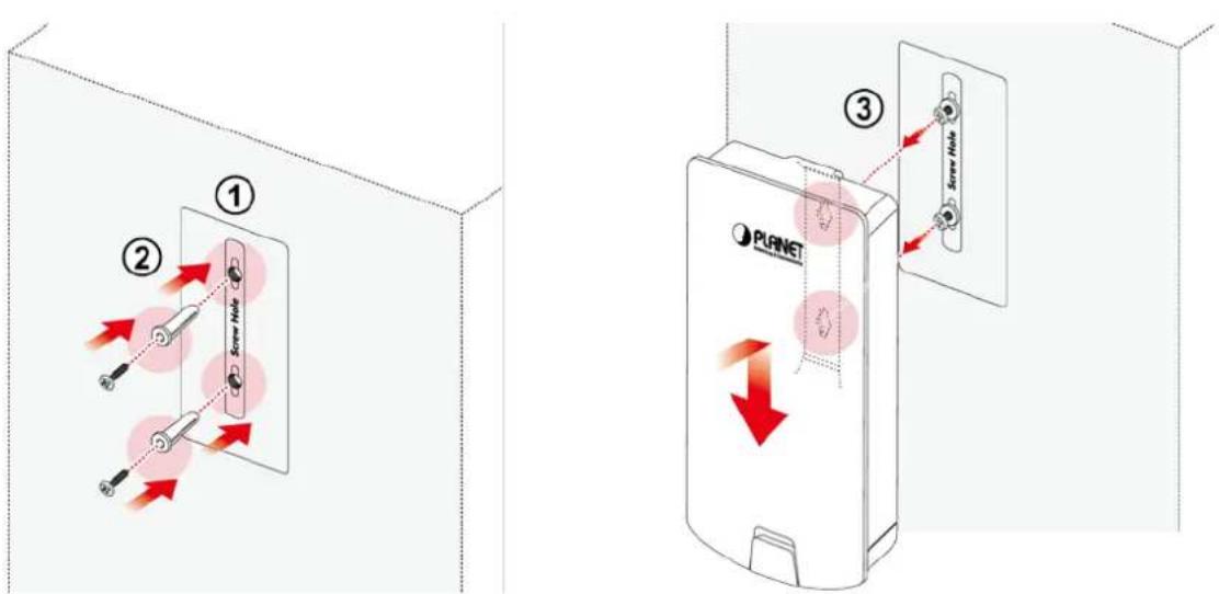
Figure 3-4 Wall Mounting
Chapter 4. Quick Installation Guide
This chapter will show you how to configure the basic functions of your AP within minutes.

A computer with wired Ethernet connection to the Wireless AP is required for the first-time configuration.
4.1 Manual Network Setup -- TCP/IP Configuration
The default IP address of the WBS-200N and WAP-200N is 192.168.1.253. And the default Subnet Mask is 255.255.255.0. These values can be changed as you desire. In this guide, we use all the default values for description.
Connect the WBS-200N or WAP-200N with your PC via an Ethernet cable which is then plugged into a LAN port of the PoE injector with one end and into a LAN port of the PC with the other end. Then power on the WBS-200N and WAP-200N via PoE injector or PoE switch.
In the following sections, we'll introduce how to install and configure the TCP/IP correctly in Windows 7. And the procedures in other operating systems are similar. First, make sure your Ethernet adapter is working, and refer to the Ethernet adapter's manual if needed.
4.1.1 Configuring the IP Address Manually
Summary:
■ Set up the TCP/IP Protocol for your PC.
- Configure the network parameters. The IP address is 192.168.1.xxx ("xxx" is any number from 2 to 252), Subnet Mask is 255.255.255.0.
1 Select Use the following IP address radio button.
2 If the AP's LAN IP address is 192.168.1.253, enter IP address 192.168.1.x (x is from 2 to 254 except 192.168.1.253), and Subnet mask is 255.255.255.0.
3 Select Use the following DNS server addresses radio button. In the Preferred DNS Server field, you can enter the DNS server IP address which has been provided by your ISP
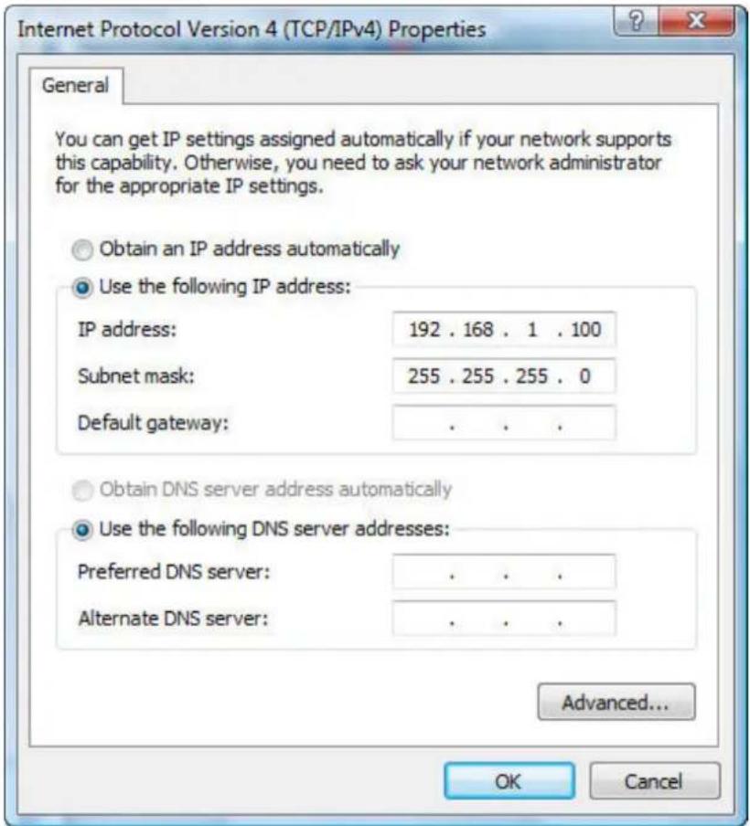
Figure 4-1 TCP/IP Setting
Now click OK to save your settings.
Now, you can run the ping command in the command prompt to verify the network connection between your PC and the AP. The following example is in Windows 7 OS. Please follow the Steps below:
- Click on Start > Run.
- Type "cmd" in the Search box.
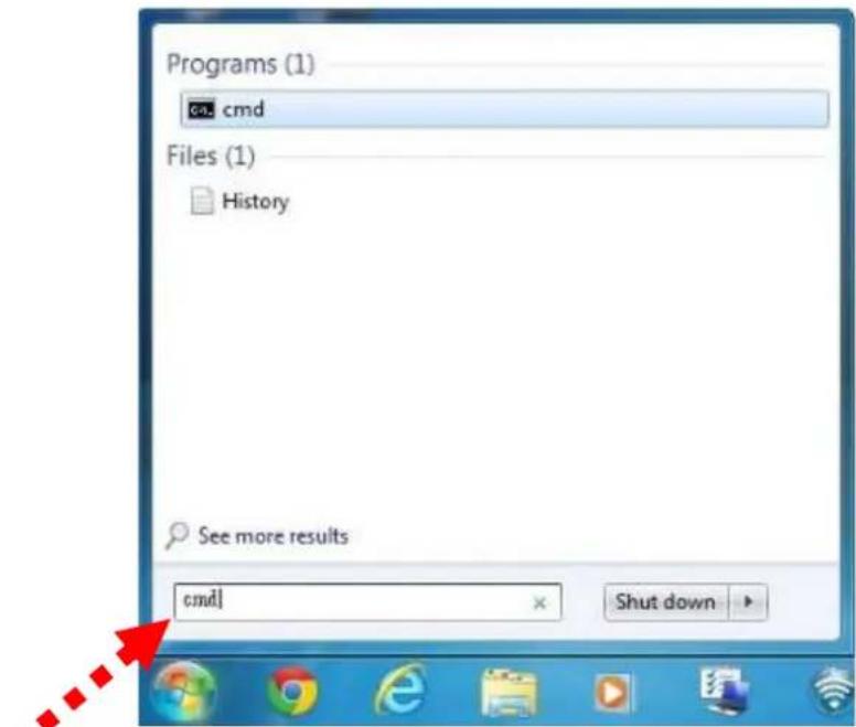
Figure 4-2 Windows Start Menu
- Open a command prompt and type ping 192.168.1.253, and then press Enter.
If the result displayed is similar to Figure 4-3, it means the connection between your PC and the AP has been established well.
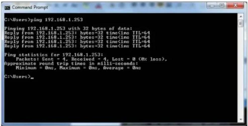
Figure 4-3 Successful result of Ping command
If the result displayed is similar to Figure 4-4, it means the connection between your PC and the AP has failed.
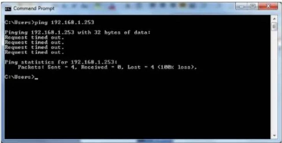
Figure 4-4 Failed result of Ping command
If the address is 0.0.0.0, check your adapter installation, security settings, and the settings on your AP. Some firewall software programs may block a DHCP request on newly installed adapters.
4.2 Starting Setup in the Web UI
It is easy to configure and manage the WBS-200N or WAP-200N with the web browser.
Step 1. To access the configuration page, open a web browser and enter the default IP address http://192.168.1.253 in the web address field of the browser.

Figure 4-5 Login by default IP address
After a moment, a login window will appear. Enter admin for the User Name and Password, both in lower case letters. Then click the OK button or press the Enter key.
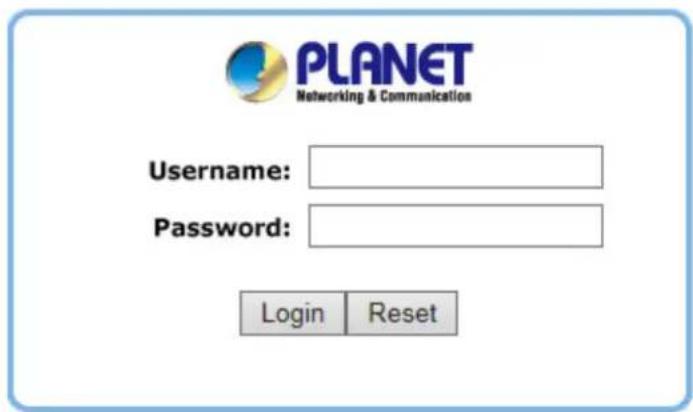
Figure 4-6 Login Window
Default IP Address: 192.168.1.253
Default User Name: admin
Default Password: admin

If the above screen does not pop up, it may mean that your web browser has been set to a proxy. Go to Tools menu> Internet Options> Connections> LAN Settings in the screen that appears, cancel the Using Proxy checkbox, and click OK to finish it.
After you enter into the Web User Interface, click Operation Mode at the left hand side of the screen to configure the wireless connection. Once the basic configuration of the device is done, go to the Save/Reload page to save and apply the changes.
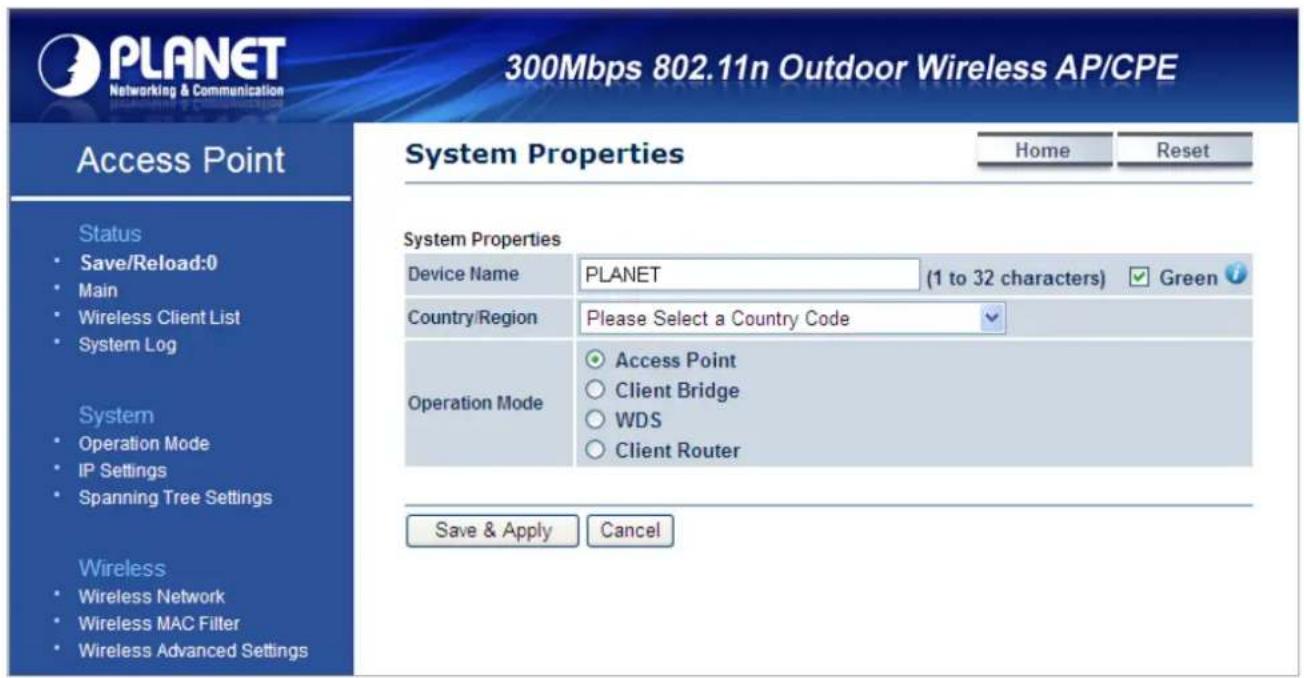
Figure 4-7 Web UI Screenshot
You can choose an Operation Mode according to your application. Please refer to the instructions in the next chapter for configuring different Operation Modes.
This chapter instructs you how to quickly configure the AP/CPE in different operation modes.
5.1 Operation Mode
On this page, you can select different operation modes of the AP depending on your application, including:
| ■ Access Point | Access Point mode is used to provide wireless connectivity to wireless clients. This mode is compatible with general wireless clients. |
| ■ Client Bridge | Client Bridge mode allows the Access Point to become a wireless client to associate to another AP thus enabling the wireless capability of wired clients. |
| ■ WDS Access Point | In WDS Access Point mode, the device functions as a WDS bridge with Access Point Mode. For WDS Access Point, it can be connected by same series of devices which using the WDS station mode. In this mode, the setting is same as Access Point Mode. |
| ■ WDS Bridge | In WDS Bridge mode, the device can bridge with remote LAN networks through MAC address. This application can create two individual networks for two groups of users sharing one Internet. The advantage of WDS is the Layer 2 transparent bridging and broadcasting across wireless connections so that all connected network devices form one common broadcast domain. |
| NOTE: The WDS mode is a non-standard extension to the IEEE 802.11 standard, which implemented differently in wireless driver and firmware making them incompatible with each other. In order to use WDS, the same model of devices should be used. | |
| ■ WDS Station | In WDS Station mode, the device functions as a wireless client which can bridge the remote WDS Access Point with SSID. In this mode, the setting is same as Client Bridge mode. |
| ■ Client Router | With Client Router (Wireless ISP) mode, the device can connect to a wireless network and share the Internet connection to the WISP subscribers.On the LAN side, the device acts like a wired router for IP sharing function. In this mode, the wireless interface acts as WAN side. |
| ■ Repeater | Repeater mode is used to extend the wireless coverage with same SSID and security. |
Go to "System → Operation Mode" page to configure the device in the operation mode which is suitable for your application. Then go to "Wireless → Wireless Network" to configure the related wireless settings of each mode.
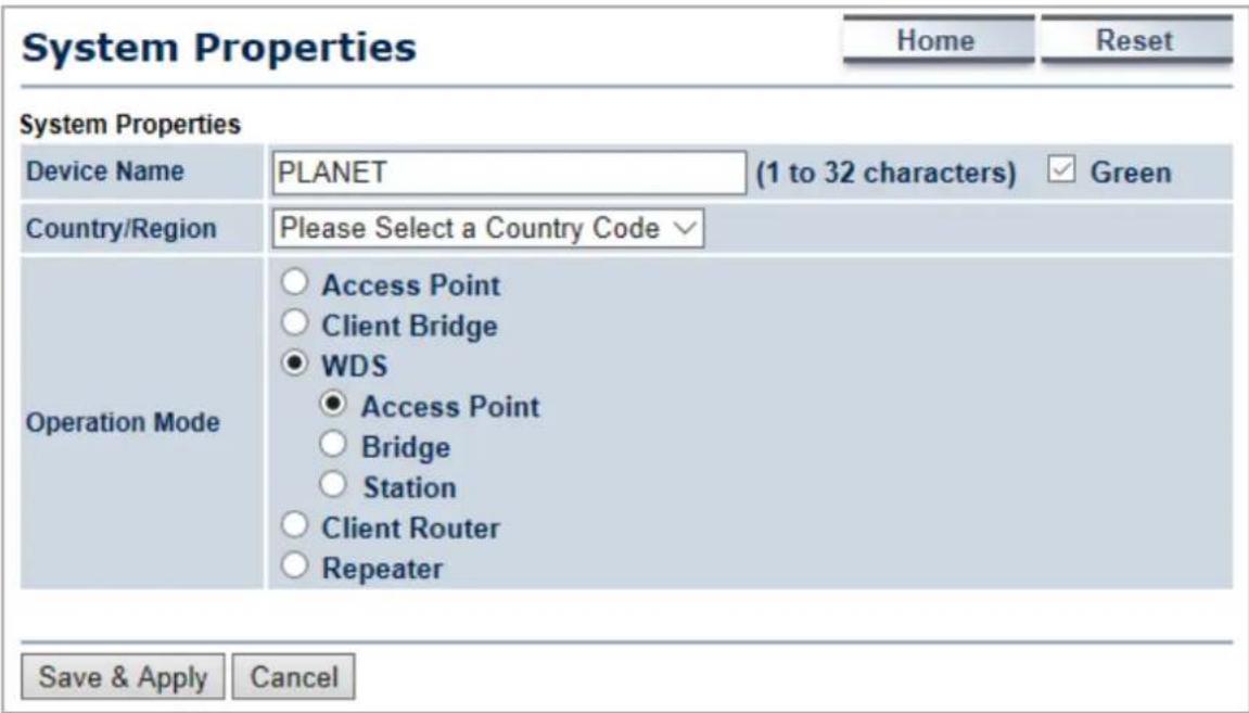
Figure 5-1 Operation Mode – All
The page includes the following settings:
| Object Description | |
| • Device Name | Enter a name for the device (1-32 characters). The name you type appears in SNMP management. This name is not the SSID and is not broadcast to other devices. |
| • Green | Disable the green option to enable transmit power to be configured manually. Keep it as default setting to prevent violating regional regulation unless your configuration meets the regulation. |
| • Country/Region | Select a Country/Region to conform to local regulations. |
| • Operation Mode | Use the radio button to select an operation mode. |
| • Save & Apply | Click Save & Apply to save changes. |
| • Cancel | Click Cancel to cancel the unsaved changes and revert to the previous settings. |
5.1.1 Access Point (AP)
This section allows you to configure the AP Bridge mode to provide wireless connectivity for wireless clients.
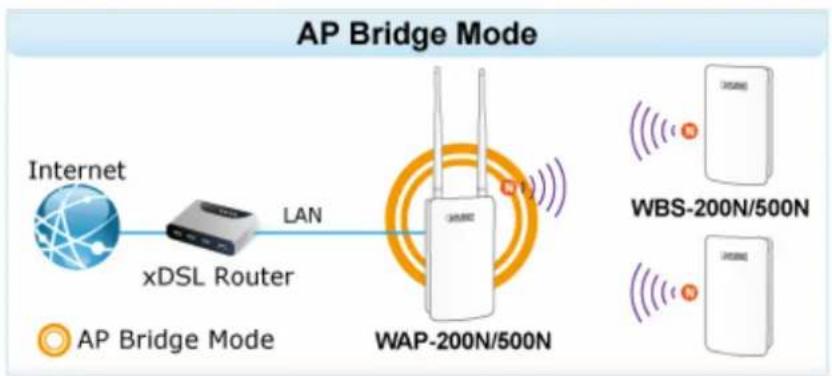
flowchart
graph LR
    A["Internet"] -->|LAN| B["xDSL Router"]
    B --> C["WAP-200N/500N"]
    D["AP Bridge Mode"] --> E["WBS-200N/500N"]
    E --> F["Mobile Device"]
Go to the "System → Operation Mode" page to configure the device as "Access Point" and then go to "Wireless → Wireless Network" to configure the related wireless settings.
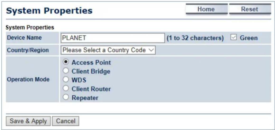
Figure 5-2 Operation Mode – AP
For the configuration example, please refer to the section "Appendix C: FAQ, Q1".
5.1.2 Client Bridge (CB)
This section allows you to configure the Client Bridge mode. In this mode, the device enables the wired client to be connected to the central site through wireless interface.
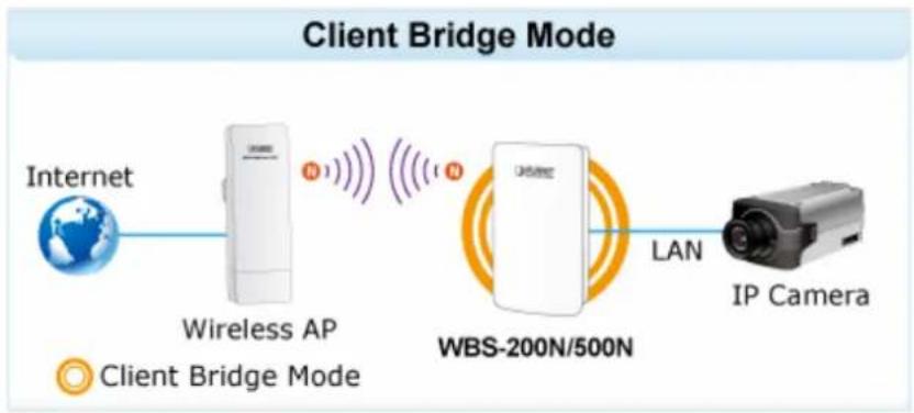
flowchart
graph LR
    A["Internet"] --> B["Wireless AP"]
    B --> C["WBS-200N/500N"]
    C --> D["IP Camera"]
    style A fill:#f9f,stroke:#333
    style B fill:#ccf,stroke:#333
    style C fill:#cfc,stroke:#333
    style D fill:#fcc,stroke:#333
Go to the "System → Operation Mode" page to configure the device as "Client Bridge" and then go to "Wireless → Wireless Network" to configure the related wireless settings.
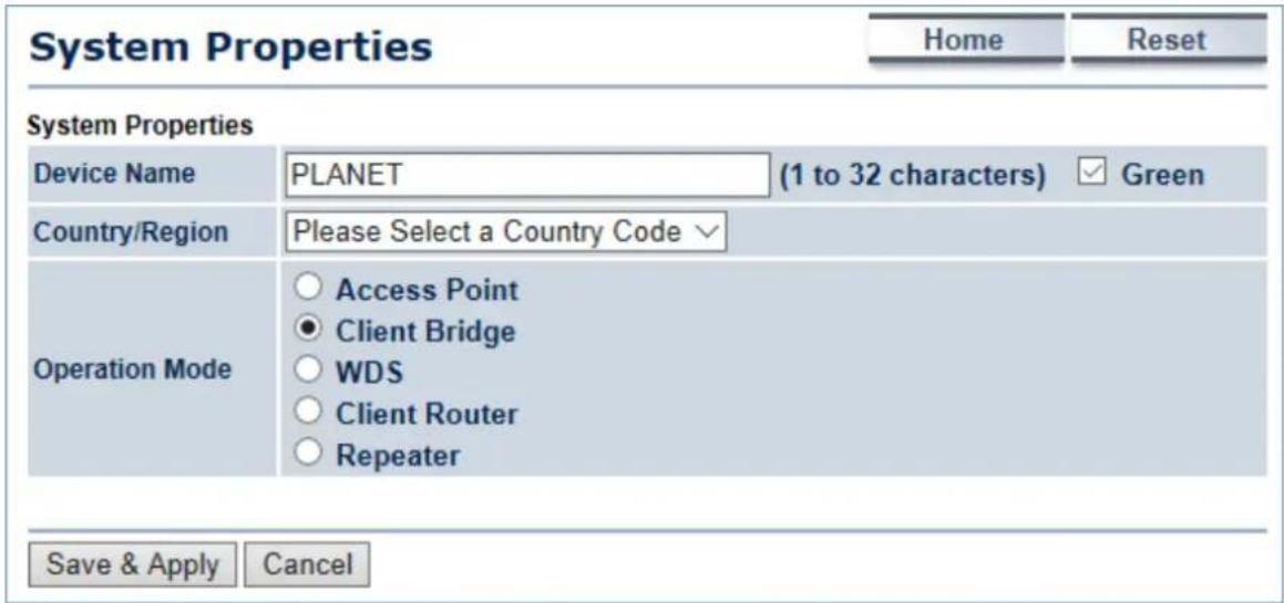
Figure 5-3 Operation Mode – Client Bridge
For the configuration example, please refer to the section "Appendix C: FAQ, Q1".
5.1.3 WDS Access Point (WDS AP)
This section allows you to configure the WDS AP mode. In this mode, the device is acting as master AP in the WDS connection.
Go to the "System → Operation Mode" page to configure the device as "WDS Access Point" and then go to "Wireless → Wireless Network" to configure the related wireless settings.
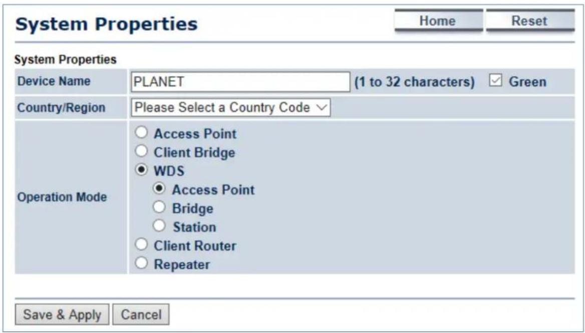
Figure 5-4 Operation Mode – WDS AP
For the configuration example, please refer to the section "Appendix C: FAQ, Q2".
5.1.4 WDS Station (WDS STA)
This section allows you to configure the WDS Station mode. In this mode, the device is acting as slave AP in the WDS connection.
Go to the "System → Operation Mode" page to configure the device as "WDS Station" and then go to "Wireless → Wireless Network" to configure the related wireless settings.
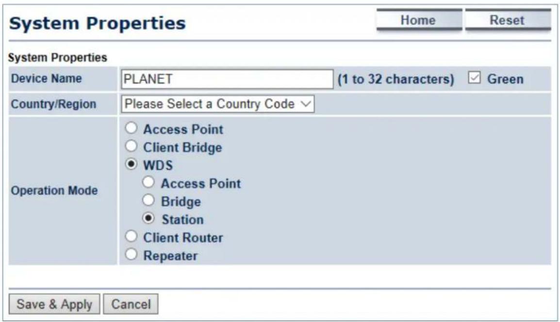
Figure 5-5 Operation Mode – WDS Station
For the configuration example, please refer to the section "Appendix C: FAQ, Q2".
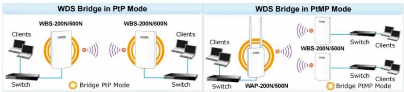
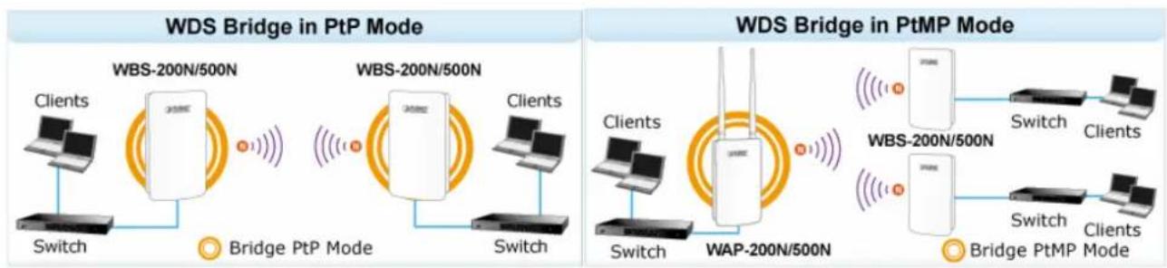
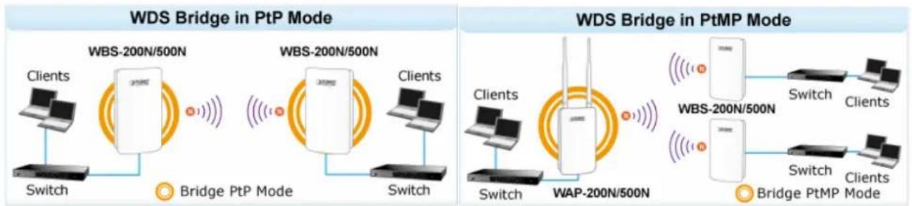
5.1.5 WDS Bridge (WDS PtP/WDS PtMP)
This section allows you to configure the WDS Bridge mode. In this mode, the device is bridging to remote node through wireless MAC address. When suppressed SSID broadcast is checked, unknown wireless clients are not allowed to connect to the AP.
flowchart
graph LR
    subgraph_PtP_Bridge_WDS_Bridge["WDS Bridge in PtP Mode"]
        A1["Clients"] --> B1["Switch"]
        B1 --> C1["Bridge PtP Mode"]
        C1 --> D1["Client"]
        D1 --> E1["Switch"]
        E1 --> F1["Bridge PtP Mode"]
        F1 --> G1["Client"]
        G1 --> H1["Switch"]
        H1 --> I1["Bridge PtP Mode"]
        I1 --> J1["Client"]
        J1 --> K1["Switch"]
        K1 --> L1["Bridge PtP Mode"]
        L1 --> M1["Client"]
        M1 --> N1["Switch"]
        N1 --> O1["Bridge PtP Mode"]
        O1 --> P1["Client"]
        P1 --> Q1["Switch"]
        Q1 --> R1["Bridge PtP Mode"]
        R1 --> S1["Client"]
        S1 --> T1["Switch"]
        T1 --> U1["Bridge PtP Mode"]
        U1 --> V1["Client"]
        V1 --> W1["Switch"]
        W1 --> X1["Bridge PtP Mode"]
        X1 --> Y1["Client"]
        Y1 --> Z1["Switch"]
        Z1 --> AA1["Bridge PtP Mode"]
        AA1 --> AB1["Client"]
        AB1 --> AC1["Switch"]
        AC1 --> AD1["Bridge PtP Mode"]
        AD1 --> AE1["Client"]
        AE1 --> AF1["Switch"]
        AF1 --> AG1["Bridge PtP Mode"]
        AG1 --> AH1["Client"]
        AH1 --> AI1["Switch"]
        AI1 --> AJ1["Bridge PtP Mode"]
        AJ1 --> AK1["Client"]
        AK1 --> AL1["Switch"]
        AL1 --> AM1["Bridge PtP Mode"]
        AM1 --> AN1["Client"]
        AN1 --> AO1["Switch"]
        AO1 --> AP1["Bridge PtP Mode"]
        AP1 --> AQ1["Client"]
        AQ1 --> AR1["Switch"]
        AR1 --> AS1["Bridge PtP Mode"]
        AS1 --> AT1["Client"]
        AT1 --> AU["Switch"]
        AU --> AV1["Bridge PtP Mode"]
        AV1 --> AW1["Client"]
        AW1 --> AX["Switch"]
        AX --> AY["Bridge PtP Mode"]
        AY --> AZ["Client"]
        AZ --> BA["Switch"]
        BA --> BB1["Bridge PtP Mode"]
        BB1 --> BC["Client"]
        BC --> BD["Switch"]
        BD --> BE1["Bridge PtP Mode"]
        BE1 --> BF["Client"]
        BF --> BG["Switch"]
        BG --> BH1["Bridge PtP Mode"]
        BH1 --> BI["Client"]
        BI --> BJ["Switch"]
        BJ --> BK1["Bridge PtP Mode"]
        BK1 --> BL["Client"]
        BL --> BM["Switch"]
        BM --> BN1["Bridge PtP Mode"]
        BN1 --> BO["Client"]
        BO --> BP["Switch"]
        BP --> BQ["Bridge PtP Mode"]
        BQ --> BR["Client"]
        BR --> BS["Switch"]
        BS --> BT1["Bridge PtP Mode"]
        BT1 --> BU["Client"]
        BU --> BV["Switch"]
        BV --> BW["Bridge PtP Mode"]
    end
Go to the "System → Operation Mode" page to configure the device as "WDS Bridge" and then go to "Wireless → WDS Link Settings" to configure the WDS bridge mode in PtP (Point to Point) or PtMP (Point to Multiple Points) applications.
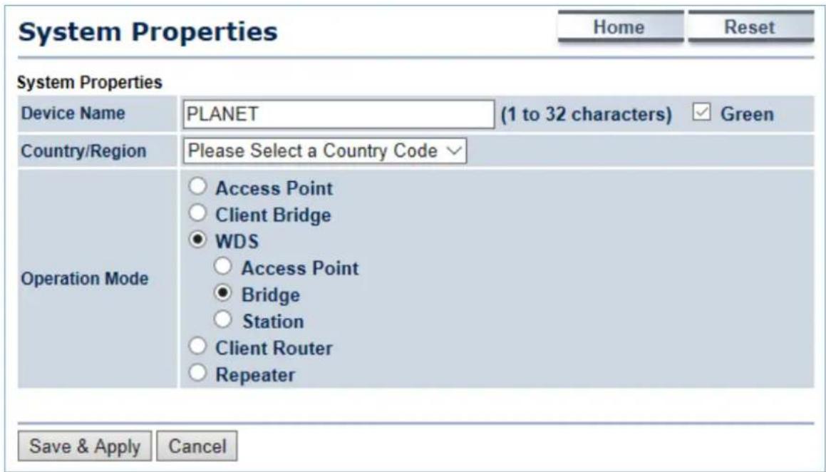
Figure 5-6 Operation Mode – WDS Bridge
Configuration Example
The following procedure will guide you to how to establish WDS connection.
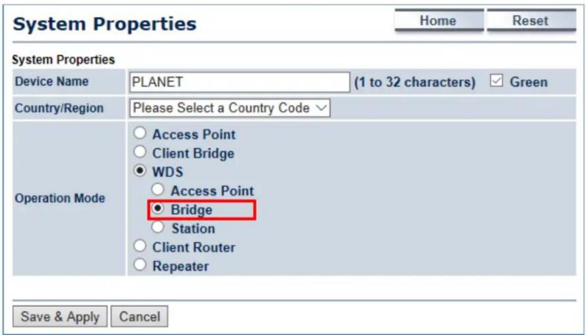
Step 1. Go to the "Operation Mode" page to configure the device as "WDS Bridge".
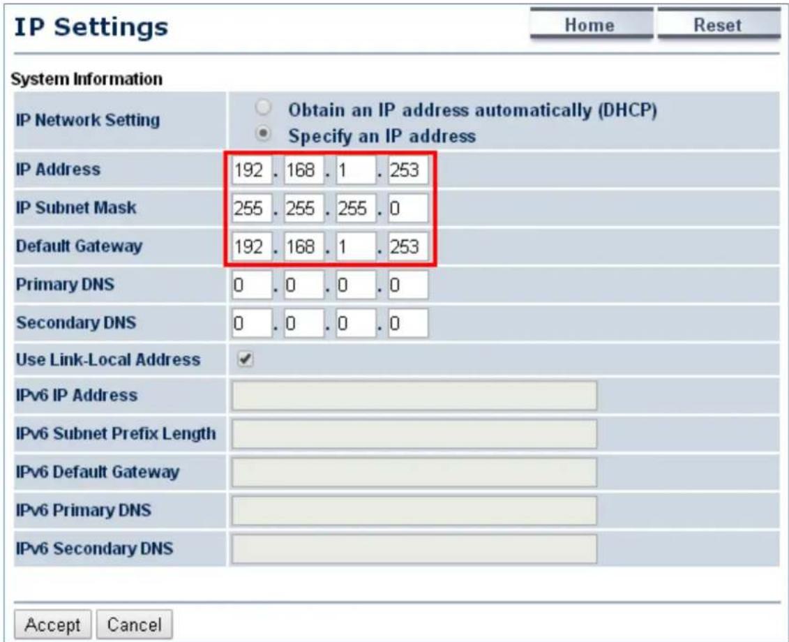
Step 2. Go to the "System → IP Settings" page to configure LAN IP of central site and remote site. The LAN IP must be different at both sites. In this example, the master AP at the central site is configured to 192.168.1.252 and the slave AP at remote site is configured to 192.168.1.253.
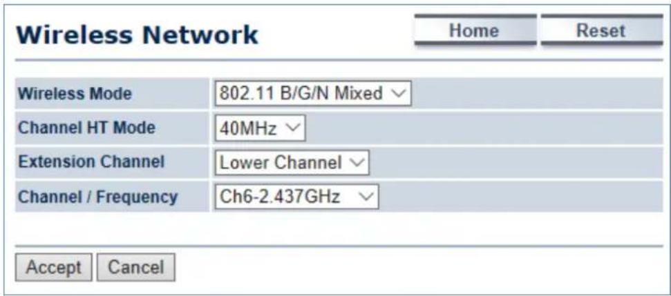
Step 3. Go to the "Wireless Wireless Network" page to configure the wireless parameters of the WDS link. In this example, we set the channel to 6 and channel width to 40MHz .
(1) Channel HT Mode: set to 40MHz for wider bandwidth to optimize performance
(2) Channel/Frequency: set to a fixed channel. For the WDS link, the fixed channel must be used.
Step 4. Go to the "Wireless →WDS Link Settings" page to enter the wireless MAC of the remote node and add encryption to protect the WDS link. Click Accept to save the changes.
(1) In PtMP of the master node: enter the wireless MAC of each remote slave node up to 4 entries.
(2) In PtMP, the distance from each slave node must be configured to the actual distance from each slave node to the master node. As to the master node, it should be configured to the value of the farthest node. In PtMP application, the distance from each node to master node should not have too much deviation to ensure the connection stability.
WDS Link Settings
Home
Reset

AES is strongly recommended
PtP application: enable ID1 and enter the wireless MAC of remote node
CAUTION: WDS was enabled, you need to assign Wifi Channel manually later.
PtMP application: up to 4 remote peers can be configured in the master AP
Accept
Cancel
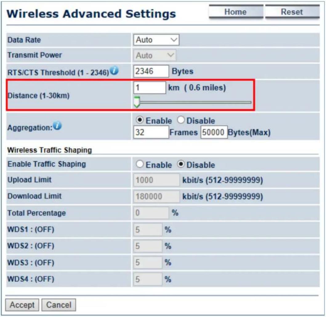
Step 5. If the connection range exceeds 1km, go to the "Wireless → Wireless Advanced Settings" page to configure the distance parameter between two sites.
(3) In PtP, the distance must be configured to the same at both sites.
(4) In PtMP, the distance at each slave nodes must be configured to the actual distance from each slave node to the master node; as to the master node should be configured to the value of the farthest node. In PtMP application, the distance from each node to master node should not have too much deviation to ensure the connection stability.
Step 6. Go to the "Status -> Save/Reload" page to save and apply settings.
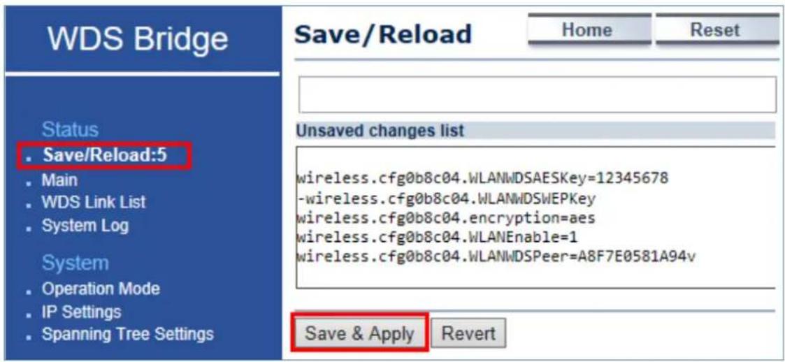
Step 7. Repeat Steps1 to 6 for each node.
Step 8. Go to the "Status -> WDS Link List" page to check the connection status.
| WDS Link Status | Home | Reset | |
| WDS Link ID | MAC Address | Link Status | RSSI (dBm) |
| 1 | a8:f7:e0:58:1a:94 | UP | -35 |
| Refresh | |||
5.1.6 Client Router (CR/WISP)
This section allows you to configure the Client Router (Wireless ISP) mode to enable clients to access Internet through remote wireless AP provided by ISP. In this mode, the DHCP server is enabled and able to assign IP address to local clients after the device is connected to remote wireless AP provided by ISP.
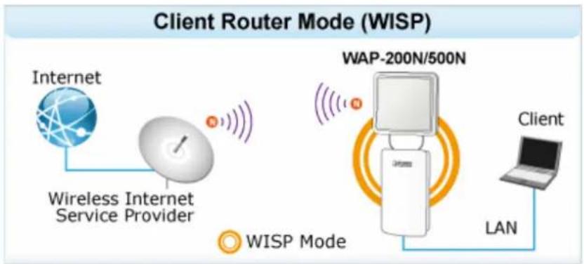
flowchart
graph LR
    A["Internet"] --> B["Wireless Internet Service Provider"]
    B --> C["WAP-200N/500N"]
    C --> D["Client"]
    D --> E["LAN"]
    E --> F["WISP Mode"]
Go to the "System → Operation Mode" page to configure the device as "Client Router" and then go to "Wireless → Wireless Network" to configure the related wireless settings.
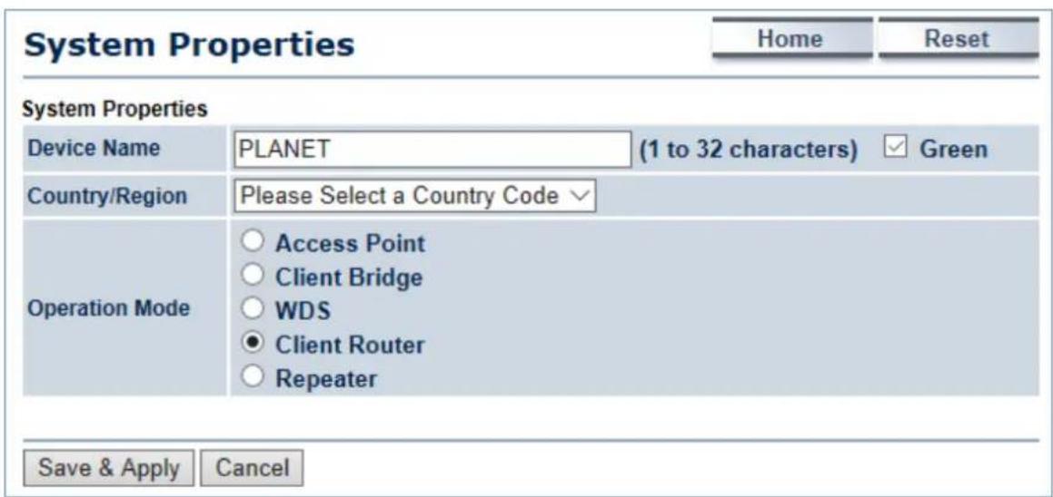
Figure 5-7 Operation Mode – Client Router (WISP)
Configuration Example
The following procedure will guide you to how to establish WISP connection.
Step 1. Go to the "Operation Mode" page to configure the device as "Client Router".
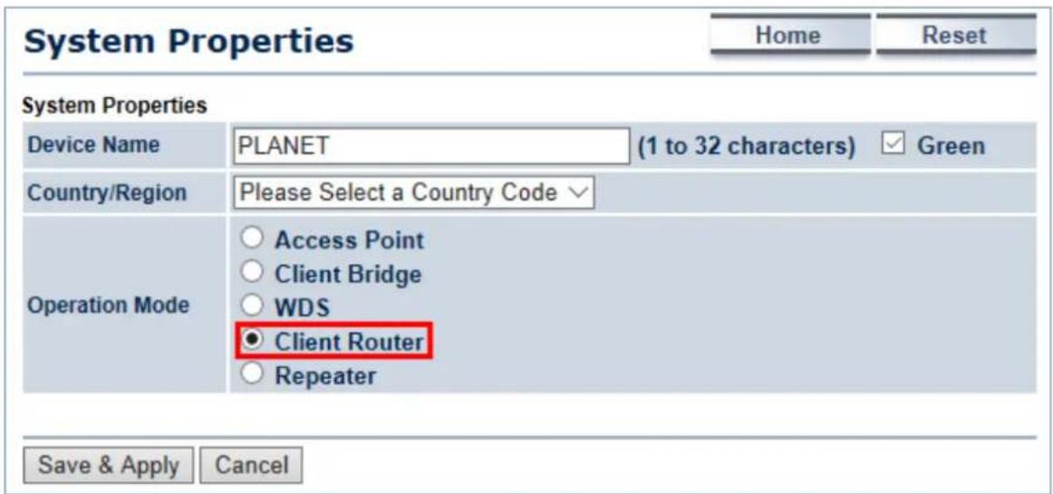
Step 2. Go to the "Router → LAN Settings" page to configure LAN IP and enable the DHCP server. The LAN IP must be a different subnet from the remote wireless AP provided by ISP.
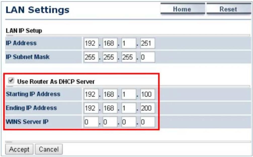
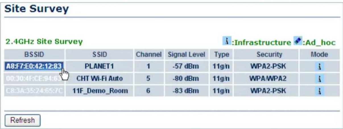
Step 3. Go to the "Wireless → Wireless Network" page to click the Site Survey button to discover the root AP.
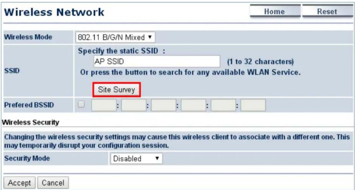
Step 4. Click the root AP as shown below and it will go back to the previous wireless network page.
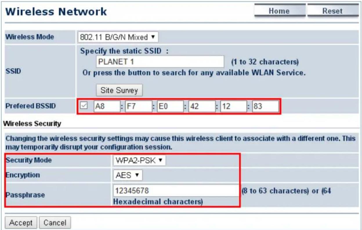
Step 5. Click the check box of the preferred BSSID and configure the encryption to be the same as the root AP. The Repeater SSID can be modified to an easily-recognized name for wireless clients. Then, click "Accept" to save the configurations.
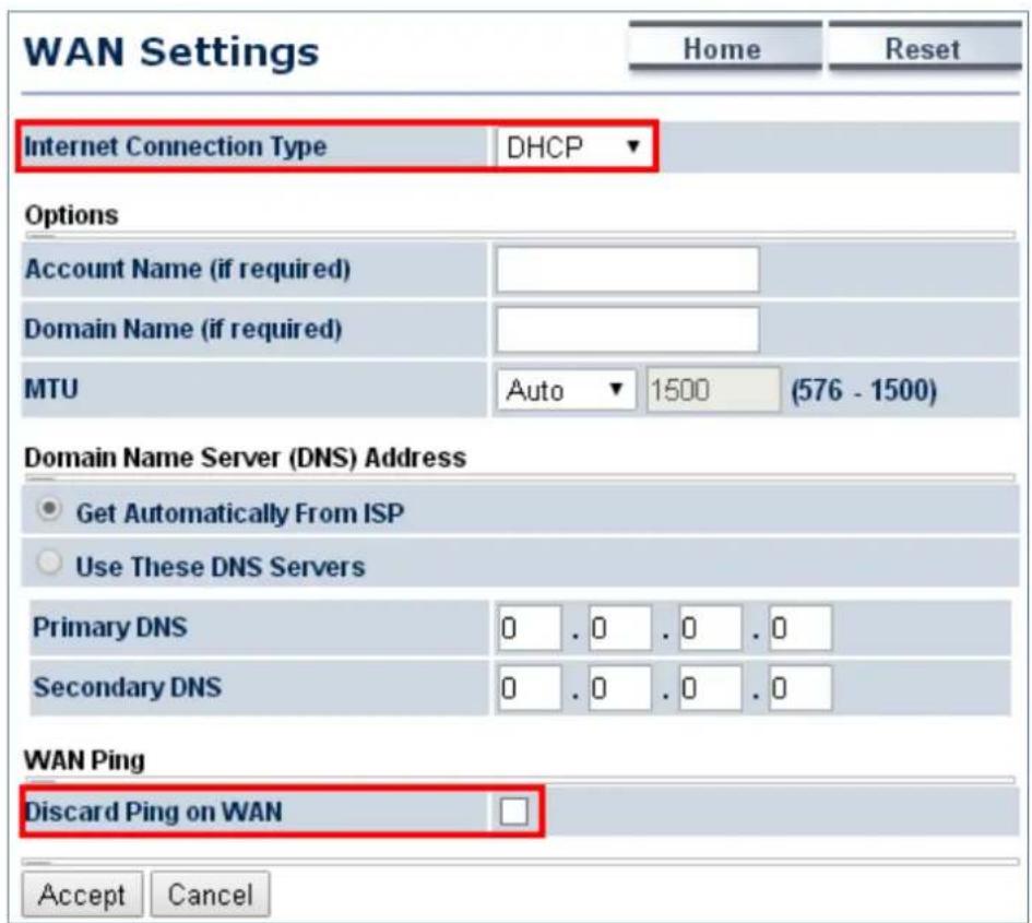
Step 6. Go to the "Router -> WAN Settings" page to configure WAN settings. The Internet connection type is provided by your ISP and should be configured properly. Disable "Discard Ping on WAN" and then you'll be able to use ping test tool of Diagnostics page to ping DNS to ensure the WAN connection is established properly through WISP mode.
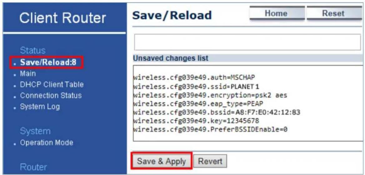
Step 7. Go to the "Status -> Save/Reload" page to save and apply settings.
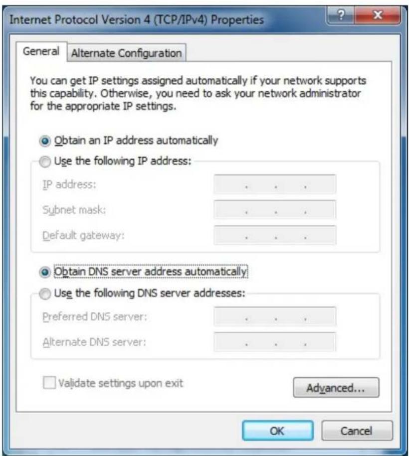
Step 8. Modify your PC/laptop connected to the LAN port of this client router to "Obtain an IP address automatically".
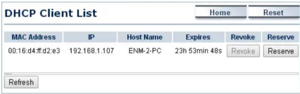
Step 9. Go to "Status -> DHCP Client Table" to ensure your PC/laptop receives the IP automatically.
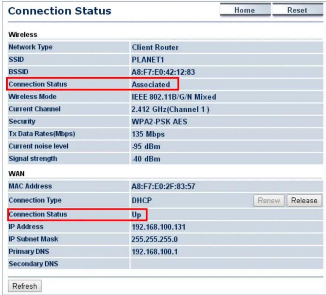
Step 10. Go to "Status -> Connection Status" to check whether the connection is established successfully.
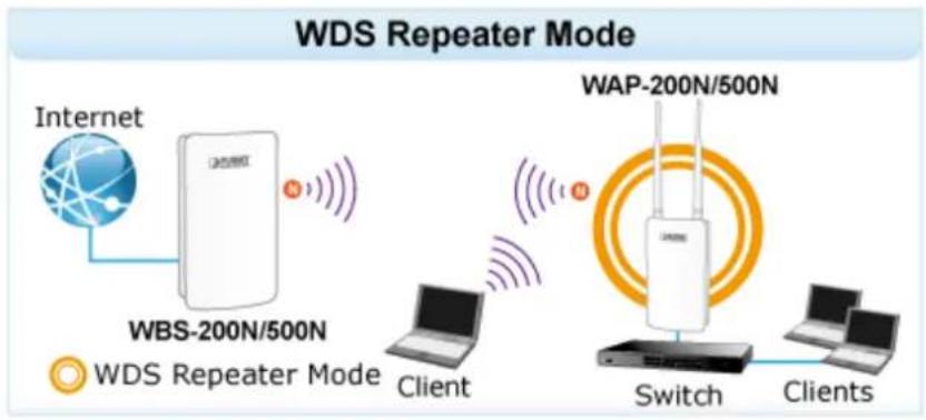
5.1.7 Repeater
This section allows you to configure the Repeater mode to extend the root AP's signal coverage.
flowchart
graph LR
    A["Internet"] --> B["WBS-200N/500N"]
    B --> C["Client"]
    D["WAP-200N/500N"] --> E["Switch"]
    E --> F["Clients"]
    style A fill:#f9f,stroke:#333
    style D fill:#bbf,stroke:#333
    style B fill:#fff,stroke:#333
    style E fill:#fff,stroke:#333
    style F fill:#fff,stroke:#333
Go to the "System → Operation Mode" page to configure the device as "Repeater" and then go to "Wireless → Wireless Network" to configure the related wireless settings.
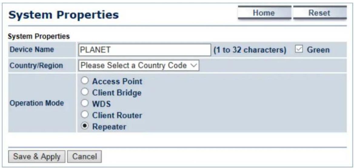
Figure 5-8 Operation Mode – Repeater
Configuration Example
The following procedure will guide you to how to establish repeater connection.
Step 1. Go to "Operation Mode" page to configure the device as "Repeater".
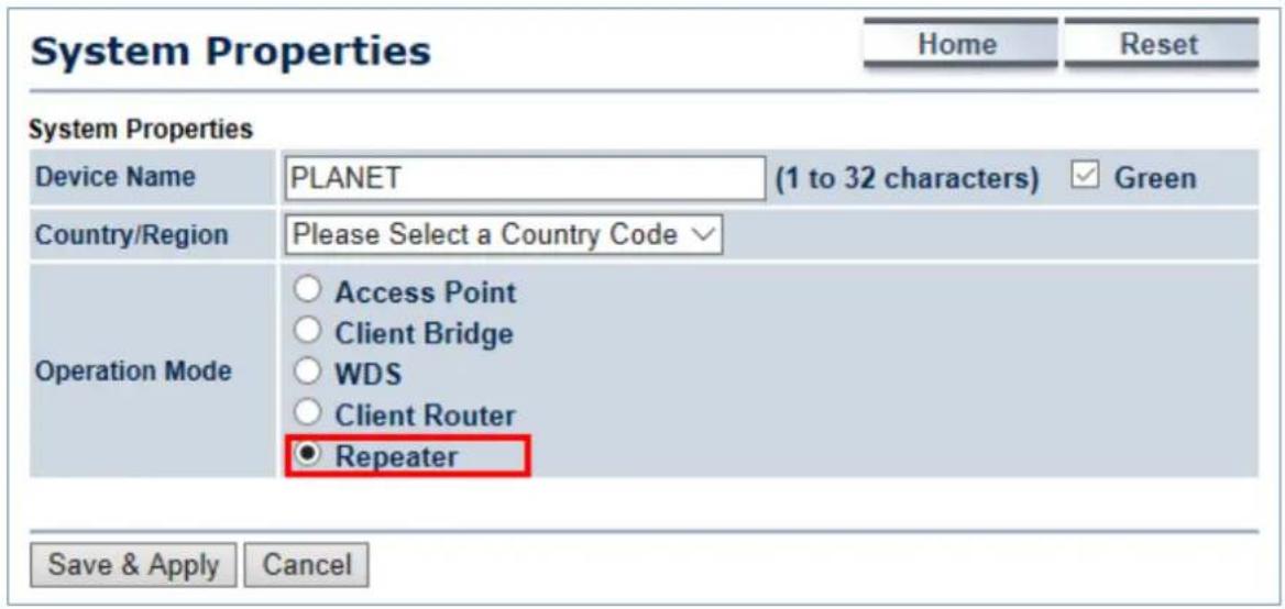
Step 2. Go to the "Wireless → Wireless Network" page to click the Site Survey button to discover the root AP.
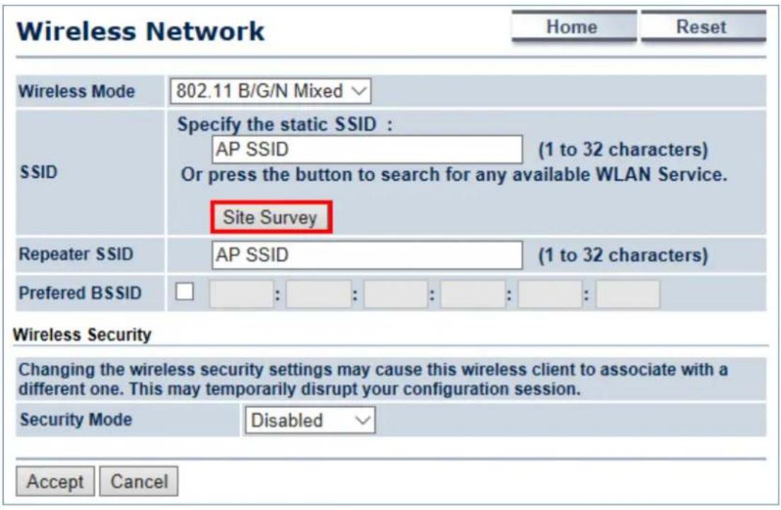
Step 3. Click the root AP as shown below and it will go back to the previous wireless network page.
Site Survey
2.4GHz Site Survey
:Infrastructure :Ad_hoc
| BSSID | SSID | Channel | Signal Level | Type | Security | Mode |
| A8:F7:E0:42:12:83 | PLANET1 | 1 | -57 dBm | 11g/n | WPA2-PSK | |
| 00:30:4F:CE:94:63 | CHT Wi-Fi Auto | 5 | -80 dBm | 11g/n | WPA/WPA2 | |
| C8:3A:35:24:65:7C | 11F_Demo_Room | 6 | -83 dBm | 11g/n | WPA2-PSK |
Step 4. Click the check box of the preferred BSSID and configure the encryption to be the same as the root AP. The Repeater SSID can be modified to an easily-recognized name for wireless clients. Then, click "Accept" to save the configurations.
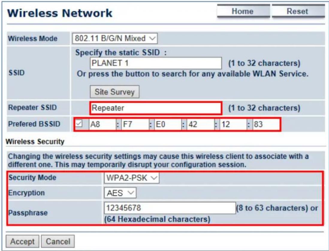
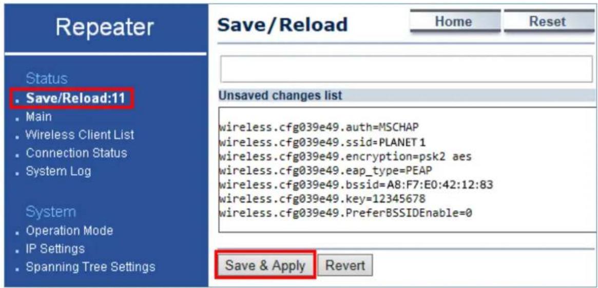
Step 5. Go to the "Status-> Save/Reload" page to save and apply settings.
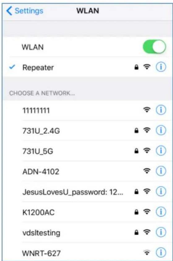
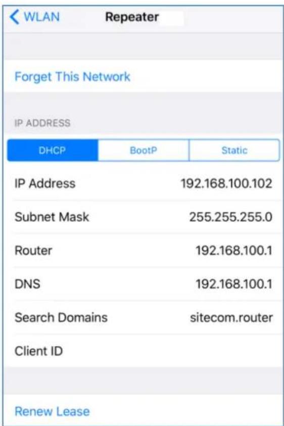
Step 6. Use a wireless client to connect to the repeater AP and ensure it is able to receive IP address from the root AP's network.
5.2 Status
This section provides the current system summary, system log and connection status including Wireless Client List, WDS Link List, DHCP Client Table and Connection Status to assist the administrator in viewing the network status.
In the upper-right corner of each function page, you can click "Home" to go back to the Main page to view the current system status and click "Reset" to force the system to reboot or reset the device to factory defaults.
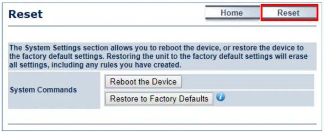
Figure 5-9 System Menu - Reset
In the upper-right corner of each function page, you can choose the Language supported in the system from the drop-down list for better user experience. Once the language is chosen, the whole web page will be translated in the language.

Figure 5-10 System Menu – Language option
5.2.1 Main
Click "Status → Main" to view the current system summary.
| Main | Home | Reset | |
| System Information | |||
| Device Name | WBS-200N | ||
| Ethernet Main MAC Address | A8:F7:E0:58:E9:73 | ||
| Ethernet Secondary MAC Address | A8:F7:E0:58:E9:73 | ||
| Wireless MAC Address | A8:F7:E0:58:E9:72 | ||
| Country | N/A | ||
| Current Time | Wed Apr 26 18:09:46 UTC 2017 | ||
| Firmware Version | 1.0.0 | ||
| LAN Settings | |||
| IP Address | 192.168.1.251 | ||
| Subnet Mask | 255.255.255.0 | ||
| DHCP Server | Enabled | ||
| RX(Packets) | 184.158 KB (2072 PKts.) | ||
| TX(Packets) | 2.94403 MB (2918 PKts.) | ||
| WAN Settings | |||
| MAC Address | A8:F7:E0:58:E9:72 | ||
| Connection Type | DHCP | ||
| Connection Status | Up | ||
| IP Address | 192.168.100.131 | ||
| IP Subnet Mask | 255.255.255.0 | ||
| Primary DNS | 192.168.100.1 | ||
| Secondary DNS | |||
| RX(Packets) | 9.13184 KB (54 PKts.) | ||
| TX(Packets) | 7.24023 KB (123 PKts.) | ||
| Current Wireless Settings | |||
| Operation Mode | Client Router | ||
| Wireless Mode | IEEE 802.11B/G/N Mixed | ||
| Channel Bandwidth | 20/40 MHz | ||
| Frequency/Channel | 2.412 GHz (Channel 1) | ||
| Wireless Network Name (SSID) | PLANET 1 | ||
| Security | WPA2-PSK AES | ||
| Distance | 1 km | ||
| RX(Packets) | 9.13184 KB (54 PKts.) | ||
| TX(Packets) | 7.24023 KB (123 PKts.) | ||
| Refresh | |||
Figure 5-11 Main Status
The page includes the following settings:
| Object Description | |
| • System Information | Shows the general system information such as device name, MAC address, country, current time, and firmware version. |
| • LAN Settings | Shows Local Area Network settings such as the LAN IP address, subnet mask, DHCP Server, and Rx/Tx packets. |
| • WAN Settings | Shows Wide Area Network settings such as the MAC address, connection type, connection status, IP address, subnet mask, primary and secondary DNS, and Rx/Tx packets. |
| • Current Wireless Settings | Shows wireless information such as operation mode, wireless mode, channel bandwidth, frequency, channel, information about each SSID, security settings, and Rx/Tx packets. |
5.2.2 Save/Reload
Click "Status → Save/Reload" and the following page will be displayed.
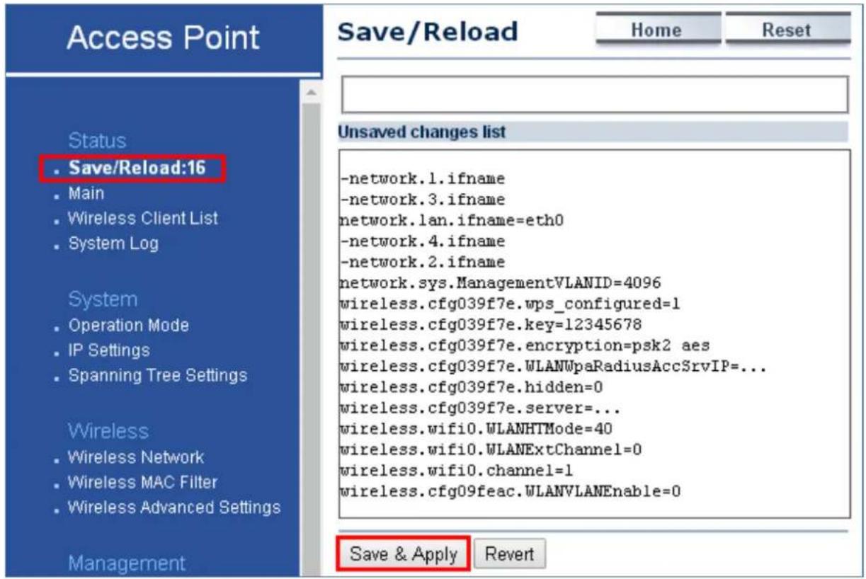
Figure 5-12 Save/Reload
Click Save & Apply to save and apply all configurations.
Click Revert to cancel the unsaved changes and revert to the previous settings that have been saved.
It's not necessary to save and apply the settings if unsaved changes list is empty.
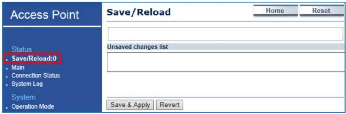
Figure 5-13 Save/Reload - Default
5.2.3 Wireless Client List
Click "Status → Wireless Client List" to view the current associated client.
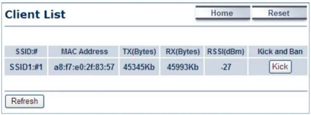
Figure 5-14 Wireless Client List
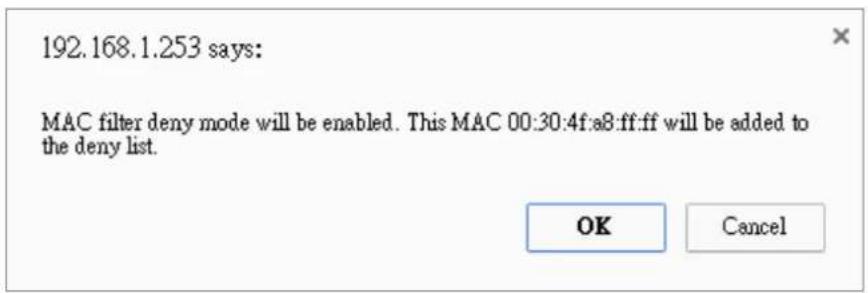
Figure 5-15 Kick the client
The page includes the following settings:
| Object Description | |
| • SSID:# | The SSID number that the client associated to. |
| • MAC Address | The MAC Address of the associated client. |
| • TX (Bytes) | The current transmit packet of the associated client. |
| • RX (Bytes) | The current received packet of the associated client. |
| • RSSI (dBm) | The current signal strength of the associated client. |
| • Kick and Ban | Click Kick to add the client to the wireless mac filtering deny list. |
5.2.4 WDS Link List
Click "Status → WDS Link List" to view the current WDS link client.
The WDS Link List is only available in WDS Bridge mode.
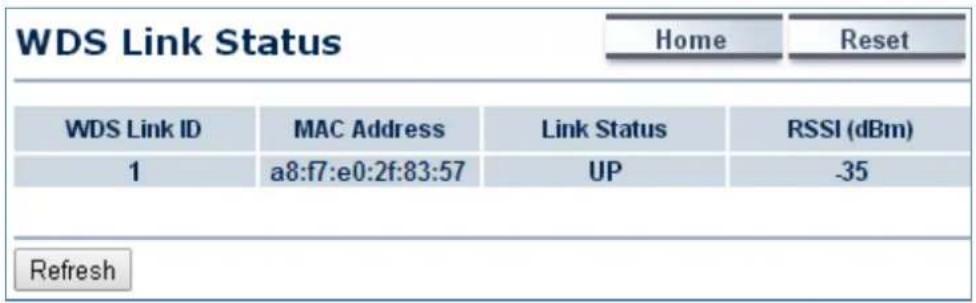
Figure 5-16 WDS Link Status
The page includes the following settings:
| Object Description | |
| WDS Link ID | The sequence number of the WDS link. |
| MAC Address | The MAC Address of the associated remote node. |
| Link Status | The current link status. |
| RSSI (dBm) | The current signal strength of the associated remote node. |
| Refresh | Click Refresh to update the current list. |
5.2.5 DHCP Client Table
Click "Status → DHCP Client Table" to view the current DHCP client.
The DHCP Client Table is only available in Client Router (WISP) mode.
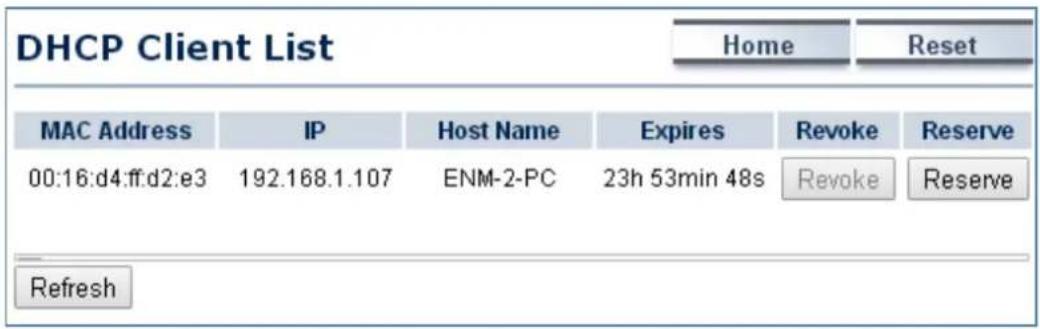
Figure 5-17 DHCP Client List
The page includes the following settings:
| Object Description | |
| • MAC Address | The MAC Address of the DHCP client. |
| • IP | The IP assigned to the DHCP client. |
| • Host Name | The Host Name of the DHCP client. |
| • Expires | The Expiry time of the DHCP client. |
| • Revoke | ClickRevoketo revoke the DHCP lease of the client. |
| • Reserve | ClickReserveto reserve the IP to the client. |
| • Refresh | ClickRefreshto update the client list. |
5.2.6 Connection Status
Click "Status → Connection Status" to view the current DHCP client.
The Connection Status is only available in the following operation modes:
(1) Client Bridge
(2) Client Router
(3) WDS Station
(4) Repeater
| Connection Status | Home | Reset | |
| Network Type | Client Bridge | ||
| SSID | PLANET1 | ||
| BSSID | A8:F7:E0:04:B4:C0 | ||
| Connection Status | Associated | ||
| Wireless Mode | IEEE 802.11B/G/N Mixed | ||
| Current Channel | 2.412 GHz(Channel 1) | ||
| Security | WPA2-PSK AES | ||
| Tx Data Rates(Mbps) | 300 Mbps | ||
| Current noise level | -95 dBm | ||
| Signal strength | -60 dBm | ||
| Refresh | |||
Figure 5-18 Connection Status
The page includes the following settings:
| Object Description | |
| • Network Type | The current operation mode of the device. |
| • SSID | The SSID of the connected AP. |
| • BSSID | The MAC Address of the connected AP. |
| • Connection Status | The status of the connection. |
| • Wireless Mode | The current wireless mode of the AP. |
| • Current Channel | The current channel used of this connection. |
| • Security | The encryption method of the AP. |
| • Tx Data Rates (Mbps) | The current data rates of the connection. |
| • Current noise level | The current noise level of the connection |
| • Signal Strength | The current signal strength of the connected AP. |
| • Refresh | Click Refresh to update the current data. |
5.2.7 System Log
Click "Status → System Log" to view the system log.
![System Log Home Reset Show log type All May 22 15: Debug ON user.notice root: starting ntpd May 22 15: Information ON cron.info crond[3020]: crond: USER root pid 1398 cmd ./etc/ho May 22 15: Notice ON user.warn kernel: Adding WDS entry for ec:a8:6b:d6:99:c4, throw May 22 15: Warning ON user.warn kernel: Node Added (NC = 1) May 22 15: Error ON daemon.debug radvd[514]: resuming normal operation May 22 15: Critical ON daemon.debug radvd[514]: attempting to reread config file May 22 15: Alert ON daemon.debug radvd[514]: attempting to reread config file May 22 15: Emergency ON user.warn kernel: Node deleted (NC = 0) May 22 15:21:25 WAP200N daemon.debug radvd[514]: resuming normal operation May 22 15:21:25 WAP200N daemon.debug radvd[514]: resuming normal operation May 22 15:21:25 WAP200N daemon.debug radvd[514]: attempting to reread config file May 22 15:21:25 WAP200N daemon.debug radvd[514]: attempting to reread config file May 22 15:21:15 WAP200N user.warn kernel: Node Added (NC = 1) May 22 15:21:15 WAP200N user.info kernel: br-lan: port 2(ath0) entering forwarding sta May 22 15:21:15 WAP200N daemon.debug radvd[514]: resuming normal operation May 22 15:21:15 WAP200N daemon.debug radvd[514]: resuming normal operation May 22 15:21:15 WAP200N daemon.debug radvd[514]: resuming normal operation May 22 15:21:15 WAP200N daemon.debug radvd[514]: resuming normal operationSave Refresh Clear](/content/2026/05/990653/images/92b3a81edf5dbbb54e126c29df2587aa6cfb33a485647f31bc48a11a759d6f81.jpg)
Figure 5-19 System Log
The page includes the following settings:
| Object Description | |
| • Show log type | Select log type to filter the records. |
| • Save | Click Save to save the records. |
| • Refresh | Click Refresh to update the current data. |
| • Clear | Click Clear to erase the records. |
5.3 System
5.3.1 IP Settings
Click "System → IP Settings" to configure the LAN IP address.
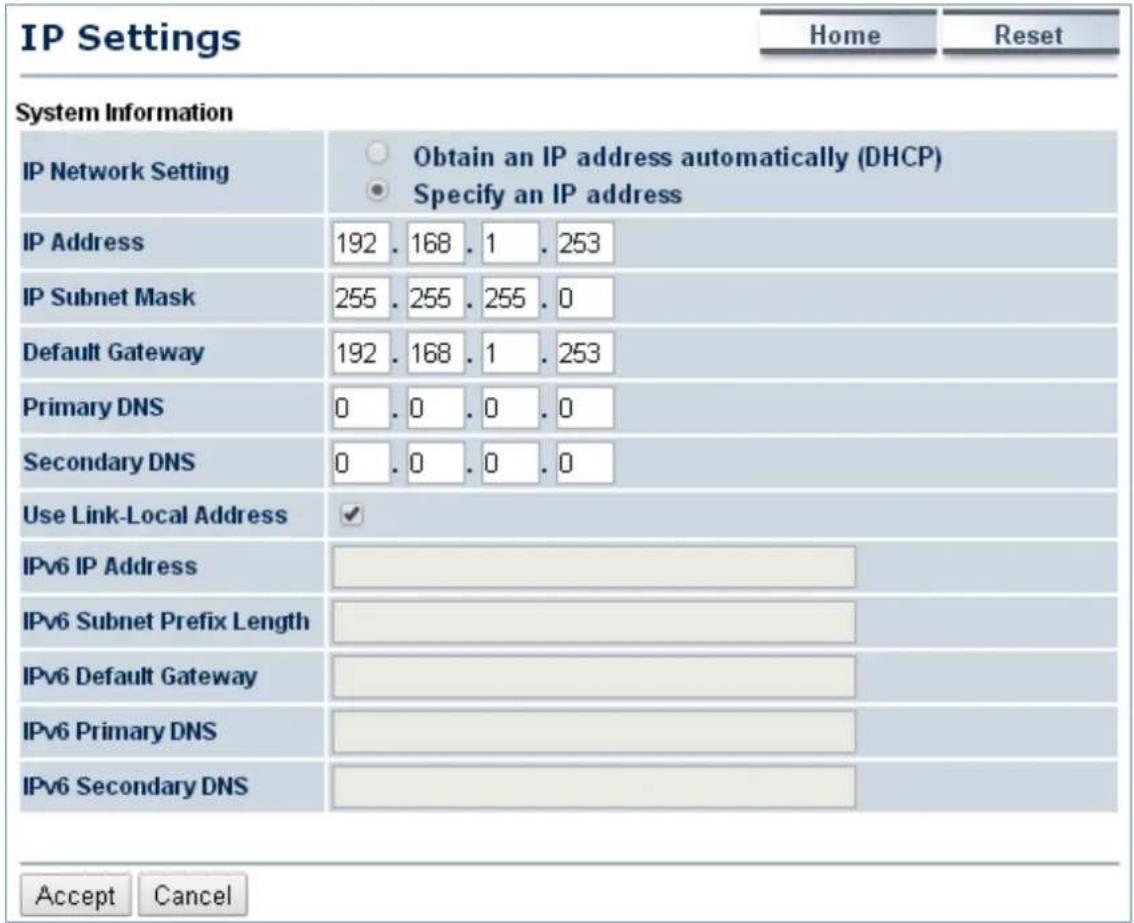
Figure 5-20 LAN IP Settings
The page includes the following settings:
| Object Description | |
| IP Network Setting | Select Obtain an IP address automatically (DHCP) to receive the IP from DHCP server.Select Specify an IP address to configure the AP to use static IP. |
| IP Address | The LAN IP of the AP.The default is 192.168.1.253. You can change it according to your needs. |
| IP Subnet Mask | The LAN subnet mask of the AP. |
| Default Gateway | Enter the Gateway IP address of the AP. |
| Primary DNS | Enter the primary DNS server of the AP. |
| Secondary DNS | Enter the secondary DNS server of the AP. |
| Use Link-Local Address | Click to enable a link-local address for the AP. |
| IPv6 IP Address | Enter the IPv6 LAN IP of the AP. |
| IPv6 Subnet Prefix Length | Enter the secondary DNS server of the AP. |
| IPv6 Default Gateway | Enter the IPv6 Gateway IP address of the AP. |
| IPv6 Primary DNS | Enter the IPv6 primary DNS server of the AP. |
| IPv6 Secondary DNS | Enter the IPv6 secondary DNS server of the AP. |
| Accept | Click Accept to apply the new settings. |
| Cancel | Click Cancel to cancel the unsaved changes and revert to the previous settings. |
5.3.2 Spanning Tree Settings (STP)
The Spanning Tree Settings (STP) protocol allows network to provide a redundant link in the event of a link failure. It is advised to turn on this option for multi-point bridge network to avoid network loop.
Click "System → Spanning Tree Settings" to enable/disable Spanning Tree Settings.
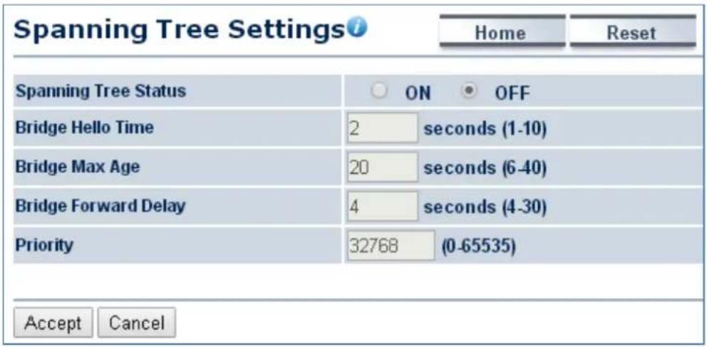
Figure 5-21 Spanning Tree Settings
The page includes the following settings:
| Object Description | |
| • Spanning Tree Status | Click ON to enable or click OFF to disable the option. |
| • Bridge Hello Time | Specify Bridge Hello Time, in seconds. This value determines how often the AP sends hello packets to communicate information about the topology throughout the entire Bridged Local Area Network. |
| • Bridge Max Age | Specify Bridge Max Age, in seconds. If another bridge in the spanning tree does not send a hello packet for a long period of time, it is assumed to be dead. |
| • Bridge Forward Delay | Specify Bridge Forward Delay, in seconds. Forwarding delay time is the time spent in each of the Listening and Learning states before theForwarding state is entered. This delay is provided so that when a new bridge comes onto a busy network, it looks at some traffic before participating. |
| • Priority | Specify the Priority number. Smaller numbers have greater priority. |
| • Accept | Click Accept to apply the setting. |
| • Cancel | Click Cancel to cancel the setting. |
5.4 Router (WISP Mode Only)
5.4.1 DHCP Server Settings
Go to the "Operation Mode" page to configure the device as "Client Router" and then go to "Router → LAN Settings" to configure the device's LAN IP settings in client router mode.
On this page, enable the DHCP server to assign IP address to local wired/wireless clients after the device is connected to the remote AP supplied by wireless ISP.
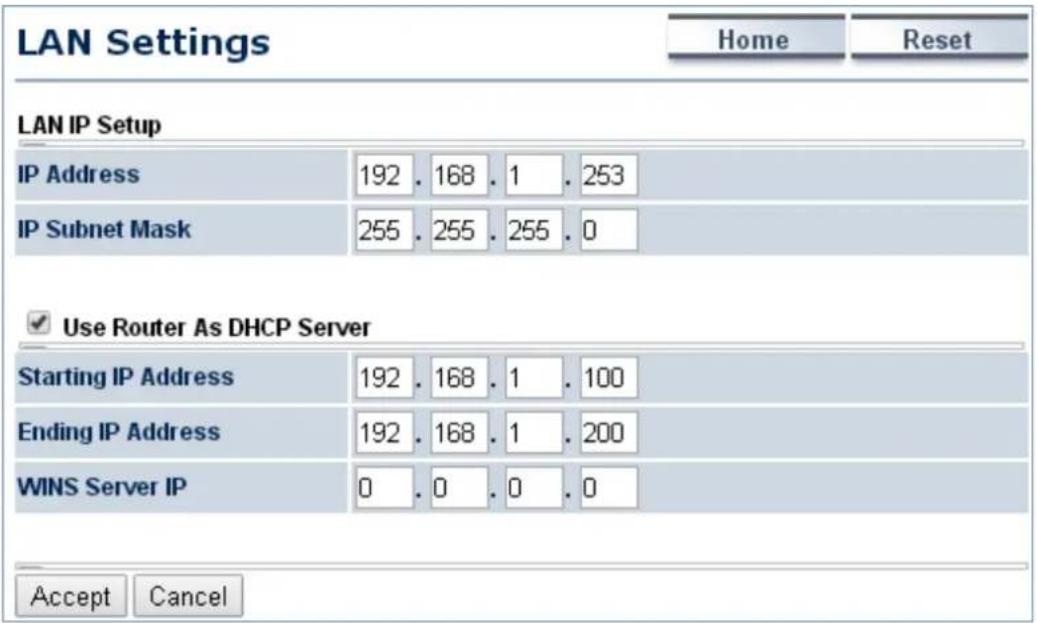
Figure 5-22 DHCP Server Settings
The page includes the following settings:
| Object Description | |
| • IP Address | The LAN IP of the AP. |
| • IP Subnet Mask | The LAN subnet mask of the AP. |
| • Use Router As DHCP Server | Select it to enable DHCP server. In here the device is acting as a router. |
| • Starting IP Address | Specify the starting IP address for the DHCP range. |
| • Ending IP Address | Specify the ending IP address for the DHCP range. |
| • WINS Server IP | Enter the IP address of the WINS server. |
| • Accept | Click Accept to apply the setting. |
| • Cancel | Click Cancel to cancel the setting. |
5.4.2 WAN Settings
Go to the "Operation Mode" page to configure the device as "Client Router" and then go to "Router → WAN Settings" to configure the device's WAN settings in client router mode. The WAN settings should be provided by the ISP.
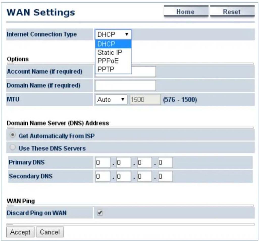
Figure 5-23 WAN Settings – All
The page includes the following common settings in each Internet Connection Type:
| Object Description | |
| • Internet Connection Type | DHCP: Dynamic IP addressing assigns a different IP address each time a device connects to an ISP service provider.Static IP: Setting a static IP address allows an administrator to set a specific IP address for the router and guarantees that it cannot beassigned a different address.PPPoE: Point-to-Point Protocol over Ethernet (PPPoE) is used mainly by ISPs that provide DSL modems to connect to the Internet.PPTP: The point-to-point tunneling protocol (PPTP) is used in association with virtual private networks (VPNs). |
| Options: This section will not be the same depending on the Internet Connection Type.Refer to settings of each corresponding section from 5.4.2.1 to 5.4.2.4 | |
| Domain Name Server (DNS) Address | |
| • Get Automatically From ISP | Select it to obtain the DNS automatically from the DHCP server. |
| • Use These DNS Servers | Select it to set up the Primary DNS and Secondary DNS servers manually. |
| • Primary DNS | Enter the primary DNS server address. |
| • Secondary DNS | Enter the secondary DNS server address. |
| WAN Ping | |
| • Discard Ping on WAN | Check it to enable pings on the WAN interface or disable to block pings on the WAN interface. |
| • Accept | Click Accept to apply the setting. |
| • Cancel | Click Cancel to cancel the setting. |
5.4.2.1. DHCP
Select DHCP and the device will automatically obtain IP addresses, subnet masks and gateway addresses from the ISP.
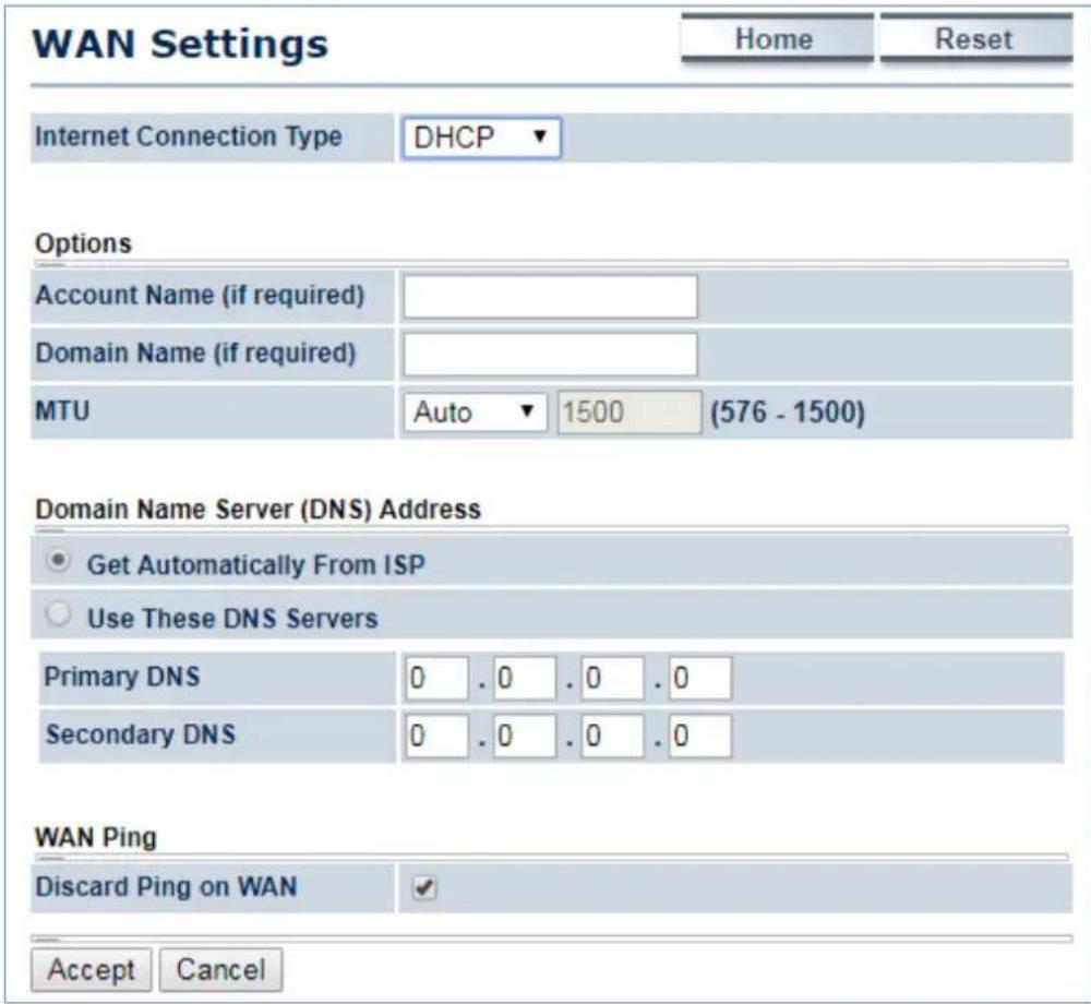
Figure 5-24 WAN Settings – DHCP
The page includes the following specific settings in DHCP type:
| Object Description | |
| • Account Name (if required) | Enter the account name provided by your ISP. |
| • Domain Name (if required) | Enter the domain name provided by your ISP. |
| • MTU | The maximum transmission unit (MTU) specifies the largest packet size permitted for an internet transmission. The factory default MTU size for DHCP is 1500. The MTU size can be set between 576 and 1500. |
| • Accept | Click Accept to apply the setting. |
| • Cancel | Click Cancel to cancel the setting. |
5.4.2.2. Static IP
If your ISP offers you static IP Internet connection type, select Static IP and then enter IP address, subnet mask, primary DNS and secondary DNS information provided by ISP in the corresponding fields.
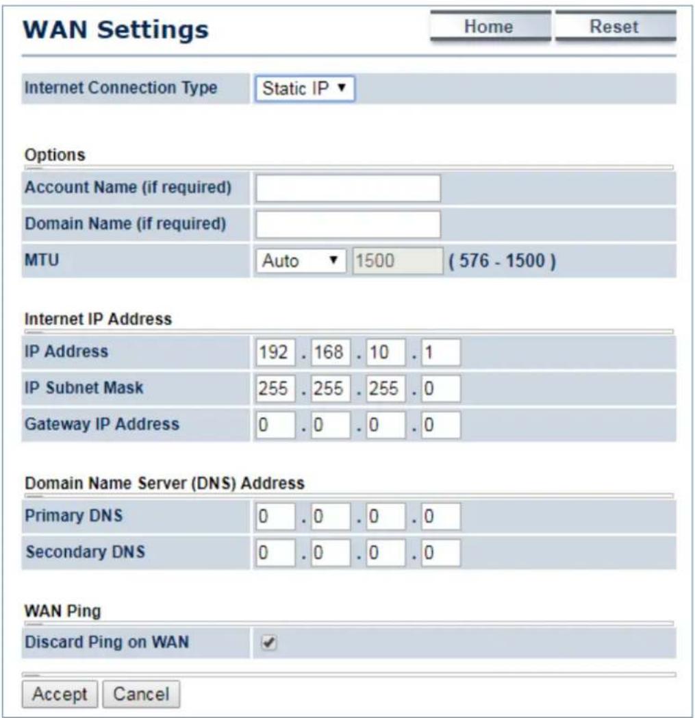
Figure 5-25 WAN Settings – Static IP
The page includes the following specific settings in Static IP type:
| Object Description | |
| • Account Name (if required) | Enter the account name provided by your ISP. |
| • Domain Name (if required) | Enter the domain name provided by your ISP. |
| • MTU | The maximum transmission unit (MTU) specifies the largest packet size permitted for an internet transmission. The factory default MTU size for static IP is 1500. The MTU size can be set between 576 and 1500. |
| • IP Address | Enter the device's WAN IP address provided by ISP. |
| • IP Subnet Mask | Enter the device's WAN IP subnet mask provided by ISP. |
| • Gateway IP Address | Enter the device's WAN Gateway IP provided by ISP. |
| • Accept | Click Accept to apply the setting. |
| • Cancel | Click Cancel to cancel the setting. |
5.4.2.3. PPPoE
Select PPPOE if ISP is using a PPPoE connection and provide you with PPPoE user name and password.
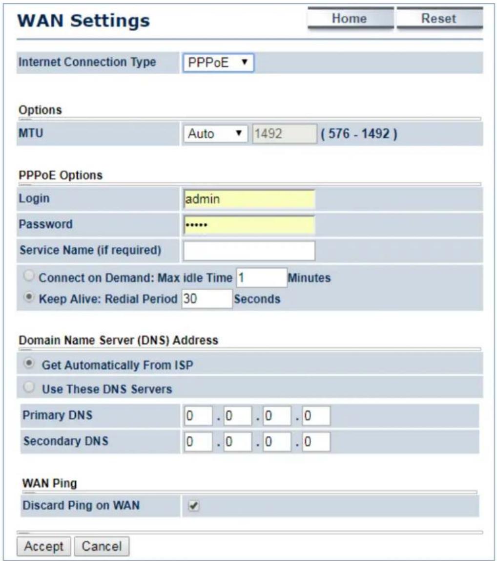
Figure 5-26 WAN Settings – PPPOE
The page includes the following specific settings in PPPoE type:
| Object Description | |
| • MTU | The maximum transmission unit (MTU) specifies the largest packet size permitted for an internet transmission. The factory default MTU size for PPPoE is 1492. The MTU size can be set between 576 and 1492. |
| • Login | Enter the username provided by ISP. |
| • Password | Enter the password provided by ISP. |
| • Service Name (if required) | Enter the service name of an ISP (optional). |
| • Connect on Demand | Select it to specify the maximum idle time. Internet connection will disconnect when it reaches the maximum idle time, but it will |
| automatically connect when user tries to access the network. | |
| Keep Alive | Select whether to keep the Internet connection always on, or enter a redial period once the internet loses connection. |
| Accept | Click Accept to apply the setting. |
| Cancel | Click Cancel to cancel the setting. |
5.4.2.4. PPTP
Select PPTP if ISP is using a PPTP connection.

Figure 5-27 WAN Settings – PPTP
The page includes the following specific settings in PPTP type:
| Object Description | |
| MTU | The maximum transmission unit (MTU) specifies the largest packet size permitted for an internet transmission. The factory default MTU size for PPTP is 1400. The MTU size can be set between 1200 and 1400. |
| IP Address | Enter the device's WAN IP address provided by ISP. |
| Subnet Mask | Enter the device's WAN IP subnet mask provided by ISP. |
| Default Gateway | Enter the device's WAN Gateway IP provided by ISP. |
| PPTP Server | Enter the IP address of the PPTP server. |
| Username | Enter the username provided by ISP. |
| Password | Enter the password provided by ISP. |
| Connect on Demand | Select it to specify the maximum idle time. Internet connection will disconnect when it reaches the maximum idle time, but it will automatically connect when user tries to access the network. |
| Keep Alive | Select whether to keep the Internet connection always on, or enter a redial period once the internet loses connection. |
| Accept | Click Accept to apply the setting. |
| Cancel | Click Cancel to cancel the setting. |
5.4.3 VPN Pass Through
VPN Pass-through allows a secure virtual private network (VPN) connection between two sites. Enabling the options on this page opens a VPN port and enables connections to pass through the AP without interruption.
Go to the "Operation Mode" page to configure the device as "Client Router" and then go to "Router → VPN Pass Through" to enable VPN pass through you required in client router mode.
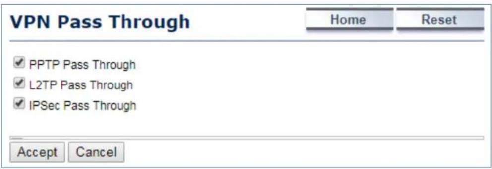
Figure 5-28 VPN Pass Through
The page includes the following settings:
| Object Description | |
| PPTP Pass Through | Check this option to enable PPTP pass-through mode. |
| L2TP Pass Through | Check this option to enable L2TP pass-through mode. |
| IPSec Pass Through | Check this option to enable IPSec pass-through mode. |
| Accept | Click Accept to apply the setting. |
| Cancel | Click Cancel to cancel the setting. |
5.4.4 Port Forwarding
Go to "Operation Mode" page to configure the device as "Client Router" and then go to "Router → Port Forwarding" to enable VPN pass through you required in client router mode.
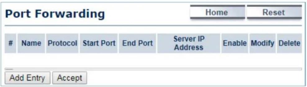
Figure 5-29 Port Forwarding
The page includes the following settings:
| Object Description | |
| # | Displays the sequence number of the forwarded port. |
| Name | Displays the name of the forwarded port. |
| Protocol | Displays the protocol to use for mapping from the following: TCP, UDP or Both. |
| Start Port | Displays the LAN port number that WAN client packets will be forward to. |
| End Port | Displays the port number that the WAN client packets are received. |
| Server IP Address | Displays the IP address of the server for the forwarded port. |
| Enable | Click to enable or disable the forwarded port profile. |
| Modify | Click to modify the forwarded port profile. |
| Delete | Click to delete the forwarded port profile. |
| Add Entry | Click Add Entry to add the new forwarding rule. |
| Accept | Click Accept to apply the setting. |
When clicking Add Entry, the following window will pop up and fill in the fields required to add a new forwarding rule.
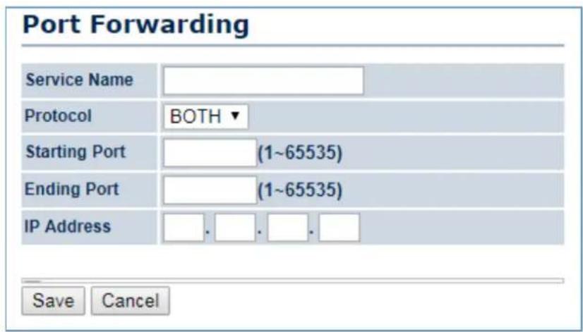
Figure 5-30 Port Forwarding
The page includes the following settings:
| Object Description | |
| Service Name | Enter a name for the port forwarding rule. |
| Protocol | Select a protocol for the application: Choices are Both, TCP and UDP. |
| Starting Port (1~65535) | Enter a starting port number. |
| Ending Port (1~65535) | Enter an ending port number.All ports numbers between the starting and ending ports will forward users to the IP address specified in the IP Address field. |
| IP Address | Enter the IP address of the server computer on the LAN network where users will be redirected. |
| Save | Click Save to save the new forwarding rule. |
| Cancel | Click Cancel to cancel the setting. |
5.4.5 DMZ Settings
The DMZ function allows the device to redirect all packets going to the WAN port IP address to a particular IP address on the LAN. The difference between the virtual server and the DMZ function is that a virtual server redirects a particular service or Internet application, such as FTP, to a particular LAN client or server, whereas a DMZ redirects all packets, regardless of the service, going to the WAN IP address to a particular LAN client or server.
Go to the "Operation Mode" page to configure the device as "Client Router" and then go to "Router → DMZ Settings" to enable/configure DMZ in client router mode.
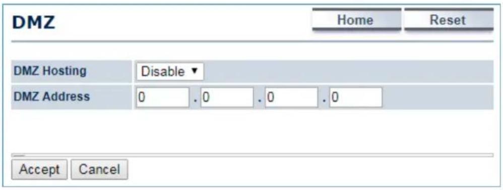
Figure 5-31 DMZ
The page includes the following settings:
| Object Description | |
| • DMZ Hosting | Select Enable DMZ to activate DMZ functionality. |
| • DMZ Address | Enter an IP address of a device on the LAN. |
| • Accept | Click Accept to apply the setting. |
| • Cancel | Click Cancel to cancel the setting. |
5.5 Wireless
This section provides wireless related settings in different operation modes.
5.5.1 Wireless Network
Click "Wireless → Wireless Network" to configure the wireless basic settings. The wireless settings on this page may vary according to the selected operation mode.
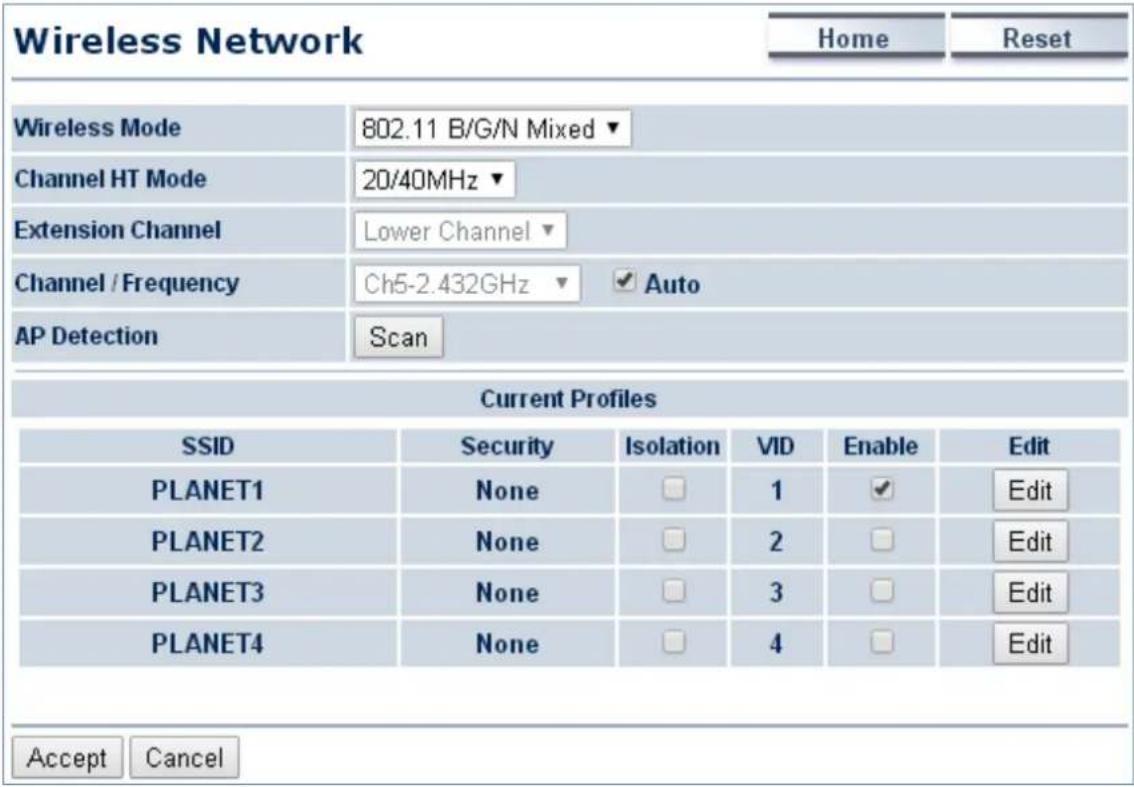
Figure 5-32 Wireless Network – AP/WDS AP Mode
In the AP/WDS AP mode, click the Edit button on the "Wireless Network" page to enter the "SSID Profile" page to configure the SSID profile for the wireless network.
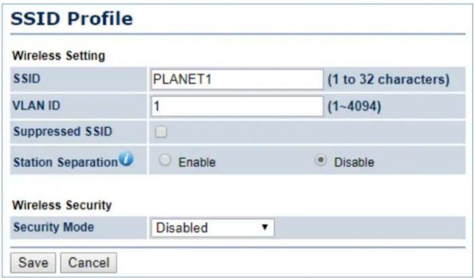
Figure 5-33 Wireless Network – SSID Profile
The page includes the following settings:
| Object Description | |
| • Wireless Mode | Wireless mode supports 802.11b/g/n mixed modes. |
| • Channel HT Mode | The default channel bandwidth is 20/40MHz. The larger the channel, the better the transmission quality and speed. |
| • Extension Channel | Select upper or lower channel. Your selection may affect the Auto channel function. |
| • Channel / Frequency | Select the channel and frequency appropriate you're your country's regulation. |
| • Auto | Check this option to enable auto-channel selection. |
| • AP Detection | AP Detection can select the best channel to use by scanning nearby areas for Access Points. |
| • Current Profile | Configure up to four different SSIDs. If many client devices will be accessing the network, you can arrange the devices into SSID groups. Click Edit to configure the profile and check whether you want to enable extra SSIDs. |
| SSID Profile | |
| • SSID | Specify the SSID for the current profile. |
| • VLAN ID | Specify the VLAN tag for the current profile. |
| • Suppressed SSID | Check this option to hide the SSID from clients. If checked, the SSID will not appear in the site survey. |
| • Station Separation | Click the appropriate radio button to allow or prevent communication between client devices. |
| • Wireless Security | Refer to section5.5.3 Security Setting. |
| • Save | ClickSaveto save changes. |
| • Cancel | ClickCancelto cancel the unsaved changes and revert to the previous settings. |
In the CB/WDS STA/CR/Repeater mode, select Security Mode on the "Wireless Network" page to configure the wireless security to be the same as the root AP's security settings.
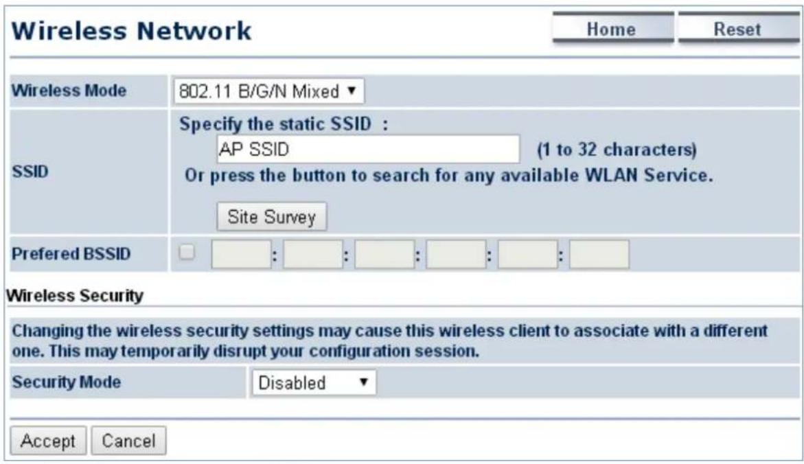
Figure 5-34 Wireless Network – CB/WDS STA/CR/Repeater Mode
The page includes the following settings:
| Object Description | |
| • Wireless Mode | Wireless mode supports 802.11b/g/n mixed modes. |
| • SSID | Specify the SSID if known. This field is completed automatically if you select an Access Point in the Site Survey. |
| • Site Survey | Scans nearby locations for Access Points. You can select a discovered Access Point to establish a connection. |
| • Prefer BSSID | Enter the MAC address if known. If you select an Access Point in the Site Survey, this field is completed automatically. |
| • Wireless Security | Refer to section5.5.3 Security Setting. |
| • Accept | Click Accept to apply the setting. |
| • Cancel | Click Cancel to cancel the unsaved changes and revert to the previous settings. |
5.5.2 WDS Link Settings
Go to the "Operation Mode" page to configure the device as "WDS Bridge" and then go to "Wireless → WDS Link Settings" to configure the WDS link settings including PtP (Point to Point) or PtMP (Point to Multiple Points) applications.
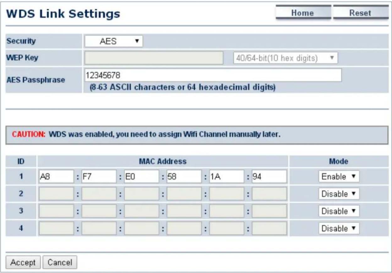
Figure 5-35 WDS Link Settings – WDS Bridge Mode
The page includes the following settings:
| Object Description | |
| • Security | Select the type of WDS security: None, WEP, or AES. |
| • WEP Key | Enter the WEP key if select security as WEP. |
| • AES Passphrase | Enter the AES passphrase if select security as AES |
| • MAC Address | Enter the wireless MAC address of the AP to which you want to extend wireless connectivity. |
| • Mode | Select Disable or Enable to disable or enable WDS. |
| • Accept | Click Accept to save the settings. |
| • Cancel | Click Cancel to cancel the unsaved changes and revert to the previous settings. |

Note
NOTE:
- The WDS link setting is only available in WDS Bridge mode and is communicating through wireless MAC address to each other by using non-standard protocol which may not be compatible with other brands/models of device. Using the same model for full compatibility is required.
- The security setting in each site of WDS link must be the same.
- The wireless channel must be fixed and must be the same in each site of WDS link.
5.5.3 Security Settings
Go to the "Wireless → Wireless Network" page to configure the security settings.
In the AP/WDS AP mode, click the Edit button on the "Wireless Network" page to enter the "SSID Profile" page and configure the wireless security for the wireless network.
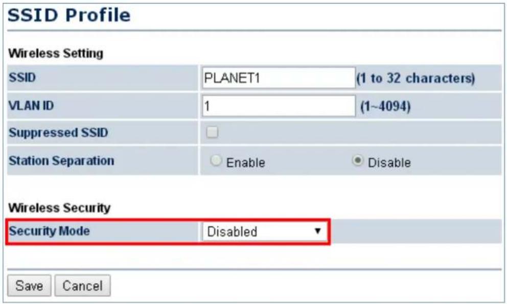
Figure 5-36 Security Settings – AP/WDS AP Mode
In the CB/WDS STA/CR/Repeater mode, select Security Mode on the "Wireless Network" page to configure the wireless security to be the same as the root AP's security settings.
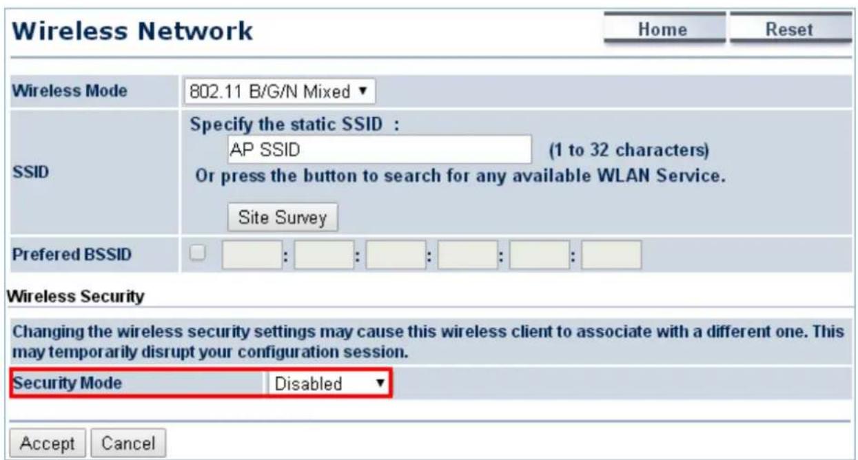
Figure 5-37 Security Settings – CB/WDS STA/CR/Repeater Mode
In the WDS Bridge mode, select Security Mode on the "WDS Link Settings" page to configure the wireless security settings. The security settings in each site of the WDS link must be configured to the same.
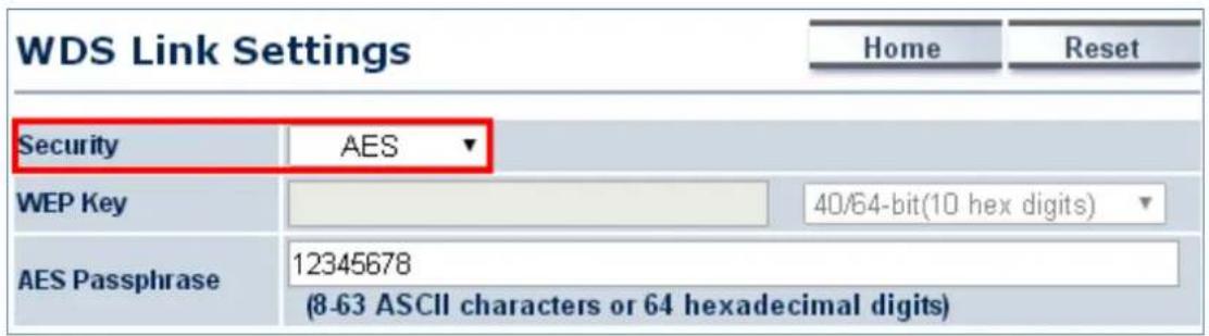
Figure 5-38 Security Settings – WDS Bridge Mode
The option includes the following settings:
| Object Description | |
| • Security Mode | Select the suitable security mode from the drop-down list to encrypt the wireless network. The options include Disabled, WEP, WPA-PSK, WPA2-PSK, WPA-PSK Mixed, WPA, WPA2, and WPA Mixed. The latest WPA2-PSK mode is strongly recommended to use. |

- The WEP and WPA/WPA2 with TKIP didn't support in pure 802.11n mode and these options will not available in pure 802.11n mode.
- In 802.11b/g /n mixed mode, if configured the security to WEP, WPA/WPA2 with TKIP, the connection mode/speed will be changed from 802.11n to 802.11g.
■ Disabled
Authentication is disabled and no password/key is required to connect to the access point.
■ WEP
WEP (Wired Equivalent Privacy) is a basic encryption. For a higher level of security, consider using the WPA encryption.
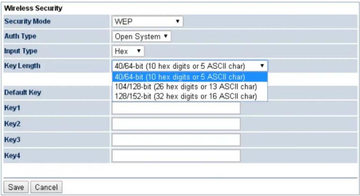
Figure 5-39 Security Settings – WEP
The security mode includes the following settings:
| Object Description | |
| • Security Mode | Select WEP from the drop-down list to configure the wireless network using WEP encryption method. |
| • Auth Type | Select Open System or Shared. |
| • Input Type | Select an input type of Hex or ASCII. |
| • Key Length | Level of WEP encryption is applied to all WEP keys.Select a 64-/128-/152-bit password length.■ 40/64-bit: enter 10 hexadecimal digits (any combination of 0-9, a-f, A-F and null key is not permitted) or 5 ASCII characters.■ 104/128-bit: enter 26 hexadecimal digits (any combination of 0-9, a-f, A-F and null key is not permitted) or 13 ASCII characters.■ 128/152-bit: enter 32 hexadecimal digits (any combination of 0-9, a-f, A-F and null key is not permitted) or 16 ASCII characters. |
| • Default Key | Select 1 – 4 to specify which of the four WEP keys the device uses as its default. |
| • Key1 – Key4 | Specify a password for the security key index. For security, each typed character is masked by a dot. |
| • Save | Click Save to save the settings. |
| • Cancel | Click Cancel to cancel the unsaved changes and revert to the previous settings. |
WPA-PSK
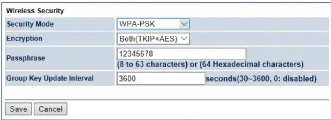
Figure 5-40 Security Settings – WPA-PSK
The security mode includes the following settings:
| Object Description | |
| • Security Mode | Select WPA-PSK from the drop-down list to configure the wireless network using WPA-PSK encryption method. |
| • Encryption | Select Both, TKIP, or AES as the encryption type.■ Both: uses TKIP and AES.■ TKIP: automatic encryption with WPA-PSK; requires passphrase.■ AES: automatic encryption with WPA2-PSK; requires passphrase. |
| • Passphrase | Specify the security password. For security, each typed character is masked by a dot. |
| • Group Key Update Interval | Specify how often, in seconds, the group key changes. |
| • Save | Click Save to save the settings. |
| • Cancel | Click Cancel to cancel the unsaved changes and revert to the previous settings. |
WPA2-PSK
The later WPA2 protocol features compliance with the full IEEE 802.11i standard and uses Advanced Encryption Standard (AES) in addition to TKIP encryption protocol to guarantee better security than that provided by WEP or WPA.
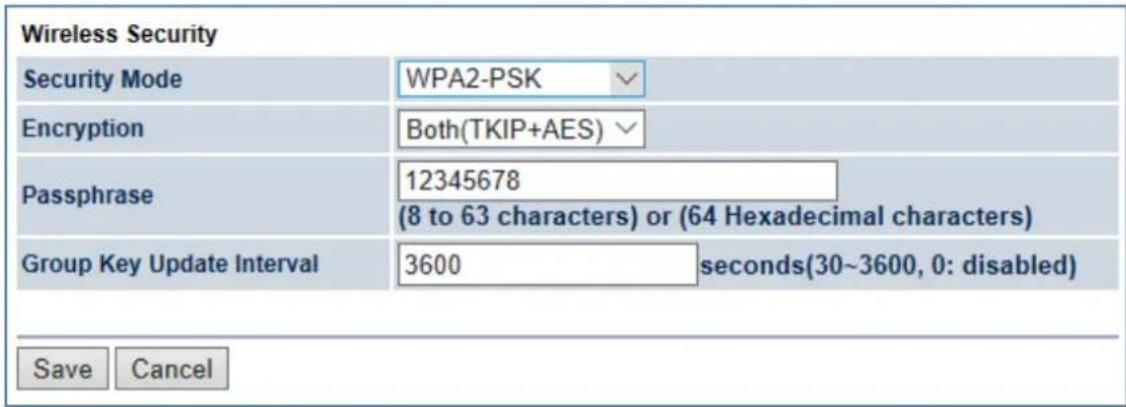
Figure 5-41 Security Settings – WPA2-PSK
The security mode includes the following settings:
| Object Description | |
| • Security Mode | Select WPA2-PSK from the drop-down list to configure the wireless network using WPA2-PSK encryption method. |
| • Encryption | Select Both, TKIP, or AES as the encryption type.■ Both: uses TKIP and AES.■ TKIP: automatic encryption with WPA-PSK; requires passphrase.■ AES: automatic encryption with WPA2-PSK; requires passphrase. |
| • Passphrase | Specify the security password. For security, each typed character is masked by a dot. |
| • Group Key Update Interval | Specify how often, in seconds, the group key changes. |
| • Save | Click Save to save the settings. |
| • Cancel | Click Cancel to cancel the unsaved changes and revert to the previous settings. |
■ WPA-PSK Mixed
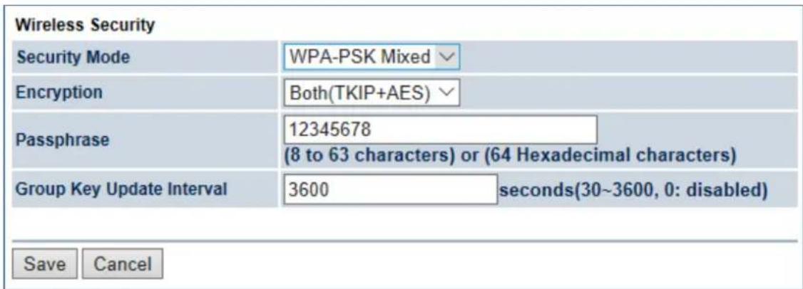
Figure 5-42 Security Settings – WPA-PSK Mixed
The security mode includes the following settings:
Object Description
| • Security Mode | Select WPA-PSK Mixed from the drop-down list to configure the wireless network using WPA-PSK Mixed encryption method. |
| • Encryption | Select Both, TKIP, or AES as the encryption type.■ Both: uses TKIP and AES.■ TKIP: automatic encryption with WPA-PSK; requires passphrase.■ AES: automatic encryption with WPA2-PSK; requires passphrase. |
| • Passphrase | Specify the security password. For security, each typed character is masked by a dot. |
| • Group Key Update Interval | Specify how often, in seconds, the group key changes. |
| • Save | Click Save to save the settings. |
| • Cancel | Click Cancel to cancel the unsaved changes and revert to the previous settings. |
■ WPA (WPA Enterprise)
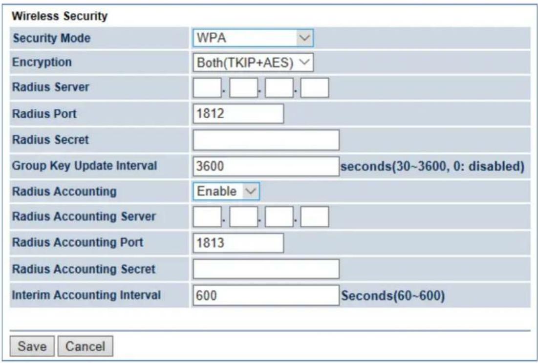
Figure 5-43 Security Settings – WPA (WPA Enterprise)
The security mode includes the following settings:
| Object Description | |
| • Security Mode | Select WPA from the drop-down list to configure the wireless network using WPA encryption method. |
| • Encryption | Select Both, TKIP, or AES as the encryption type.■ Both: uses TKIP and AES.■ TKIP: automatic encryption with WPA-PSK; requires passphrase.■ AES: automatic encryption with WPA2-PSK; requires passphrase. |
| Radius Server | Specify the IP address of the RADIUS server. |
| Radius Port | Specify the port number that your RADIUS server uses for authentication. Default port is 1812. |
| Radius Secret | Specify RADIUS secret furnished by the RADIUS server. |
| Group Key Update Interval | Specify how often, in seconds, the group key changes. |
| Radius Accounting | Select to enable or disable RADIUS accounting. |
| Radius Accounting Server | Specify the IP address of the RADIUS accounting server. |
| Radius Accounting Port | Specify the port number that your RADIUS accounting server uses for authentication. Default port is 1813. |
| Radius Accounting Secret | Specify RADIUS accounting secret furnished by the RADIUS server. |
| Interim Accounting Interval | Specify the interim accounting interval (60 - 600 seconds). |
| Save | Click Save to save the settings. |
| Cancel | Click Cancel to cancel the unsaved changes and revert to the previous settings. |
■ WPA2 (WPA2 Enterprise)
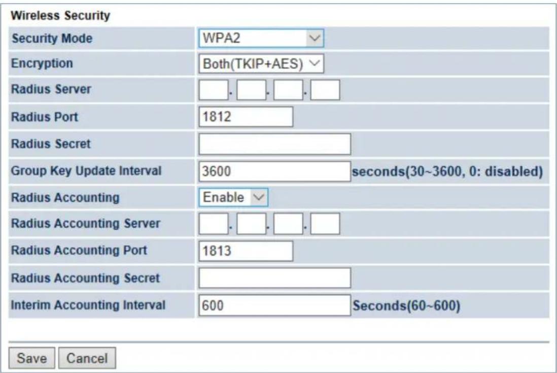
Figure 5-44 Security Settings – WPA2 (WPA2 Enterprise)
The security mode includes the following settings:
| Object Description | |
| • Security Mode | Select WPA2 from the drop-down list to configure the wireless network using WPA2 encryption method. |
| • Encryption | Select Both, TKIP, or AES as the encryption type.■ Both: uses TKIP and AES.■ TKIP: automatic encryption with WPA-PSK; requires passphrase.■ AES: automatic encryption with WPA2-PSK; requires passphrase. |
| • Radius Server | Specify the IP address of the RADIUS server. |
| • Radius Port | Specify the port number that your RADIUS server uses for authentication. Default port is 1812. |
| • Radius Secret | Specify RADIUS secret furnished by the RADIUS server. |
| • Group Key Update Interval | Specify how often, in seconds, the group key changes. |
| • Radius Accounting | Select to enable or disable RADIUS accounting. |
| • Radius Accounting Server | Specify the IP address of the RADIUS accounting server. |
| • Radius Accounting Port | Specify the port number that your RADIUS accounting server uses for authentication. Default port is 1813. |
| • Radius Accounting Secret | Specify RADIUS accounting secret furnished by the RADIUS server. |
| • Interim Accounting Interval | Specify the interim accounting interval (60 - 600 seconds). |
| • Save | Click Save to save the settings. |
| • Cancel | Click Cancel to cancel the unsaved changes and revert to the previous settings. |
■ WPA Mixed (WPA Mixed Enterprise)
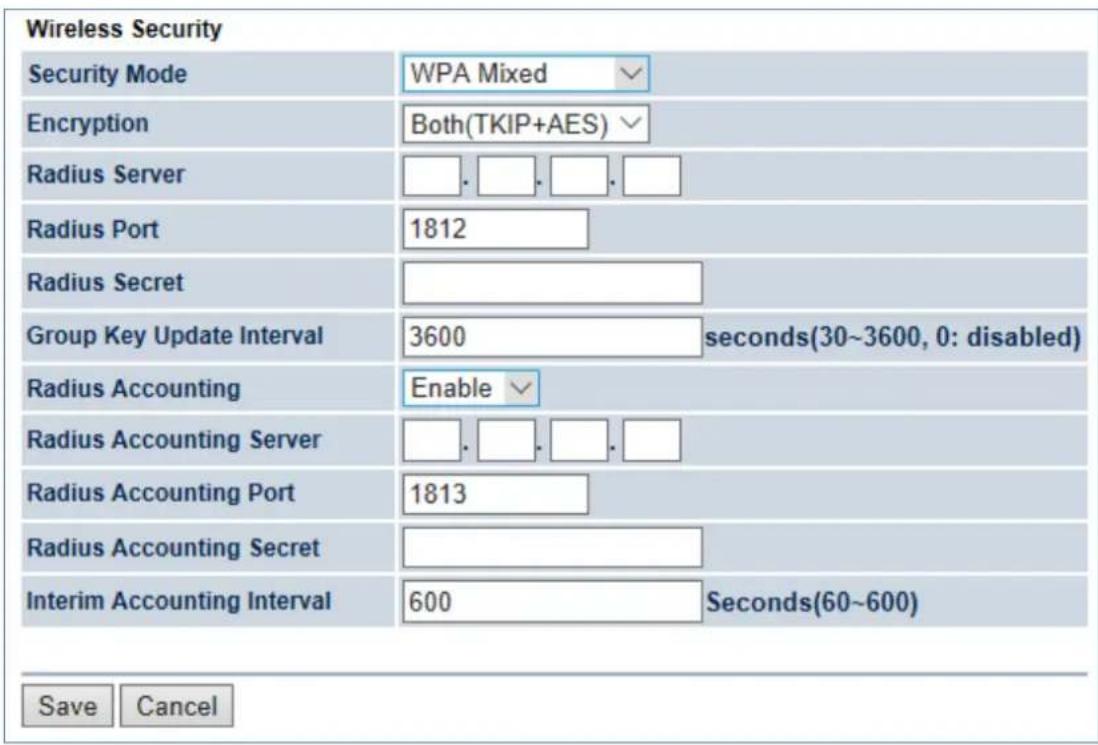
Figure 5-45 Security Settings – WPA Mixed (WPA Mixed Enterprise)
The security mode includes the following settings:
| Object Description | |
| • Security Mode | Select WPA Mixed from the drop-down list to configure the wireless network using WPA Mixed encryption method. |
| • Encryption | Select Both, TKIP, or AES as the encryption type.■ Both: uses TKIP and AES.■ TKIP: automatic encryption with WPA-PSK; requires passphrase.■ AES: automatic encryption with WPA2-PSK; requires passphrase. |
| • Radius Server | Specify the IP address of the RADIUS server. |
| • Radius Port | Specify the port number that your RADIUS server uses for authentication. Default port is 1812. |
| • Radius Secret | Specify RADIUS secret furnished by the RADIUS server. |
| • Group Key Update Interval | Specify how often, in seconds, the group key changes. |
| • Radius Accounting | Select to enable or disable RADIUS accounting. |
| • Radius Accounting Server | Specify the IP address of the RADIUS accounting server. |
| • Radius Accounting Port | Specify the port number that your RADIUS accounting server uses for authentication. Default port is 1813. |
| • Radius Accounting Secret | Specify RADIUS accounting secret furnished by the RADIUS server. |
| • Interim Accounting Interval | Specify the interim accounting interval (60 - 600 seconds). |
| • Save | Click Save to save the settings. |
| • Cancel | Click Cancel to cancel the unsaved changes and revert to the previous settings. |
5.5.4 Wireless MAC Filter
Wireless MAC Filters are used to allow or deny network access to wireless clients according to their MAC addresses. You can manually add a MAC address to restrict the permission to access the device or refer to section 5.2.3 to kick the associated client from the wireless client list.
Click "Wireless → Wireless MAC Filter" to configure the wireless access control settings.
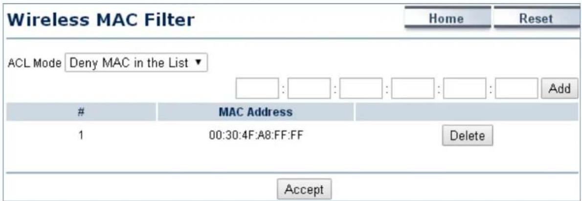
Figure 5-46 Wireless MAC Filter
The page includes the following settings:
| Object Description | |
| ACL Mode | Determines whether network access is granted or denied to clients whose MAC addresses appear in the MAC Address table on this page. The option includes Disable, Deny MAC in the list, or Allow MAC in the list. |
| Add | Enter the wireless MAC address of the client in front of the Add button and then click Add to add the new entry to the MAC filtering list. |
| # | Displays the sequence number of the entries. |
| MAC Address | Displays the MAC Address that will be denied/allowed to access this device. |
| Delete | Click Delete to remove the entry from the list. |
| Accept | Click Accept to apply the setting. |
5.5.5 Wireless Advanced Settings
Click "Wireless → Wireless Advanced Settings" to configure the wireless advanced settings.
This section allows you to configure the wireless related settings to optimize the wireless network.
| Wireless Advanced Settings | Home | Reset | ||
| Data Rate | Auto ▼ | |||
| Transmit Power | Auto ▼ | |||
| RTS/CTS Threshold (1 - 2346) | 2346 | Bytes | ||
| Distance (1-30km) | 1 km (0.6 miles) | |||
| Aggregation: | ● Enable ○ Disable 32 Frames 50000 Bytes(Max) | |||
| Wireless Traffic Shaping | ||||
| Enable Traffic Shaping | ○ Enable ● Disable | |||
| Upload Limit | 1000 kbit/s (512-99999999) | |||
| Download Limit | 180000 kbit/s (512-99999999) | |||
| Client Limit | ||||
| Frequency | Enable | Max Client | ||
| 2.4G | ✓ | 64 | ||
| Accept Cancel | ||||
Figure 5-47 Wireless Advanced Settings
The page includes the following settings:
| Object Description | |
| Data Rate | Select a data rate from the drop-down list. The data rate affects throughput. If you select a low data rate value, for example, the throughput is reduced but the transmission distance increases. The default is “Auto”. |
| Transmit Power | Configure the output transmission power of the device (Range: 11~29dBm). The PtP range less 1km should keep it as default and distance exceed 5km is suggested to highest value.The option is only allowed to be configured after disabled Green option of “Operation Mode” page. Keep it as default “Auto” setting to prevent violating regional regulation unless your configuration meets theregulation. |
| • RTS/CTS Threshold | When the length of a data packet exceeds this value, the device will send an RTS frame to the destination wireless node, and the latter will reply with a CTS frame, and thus they are ready to communicate. The default value is 2346. A small number causes RTS/CTS packets to be sent more often and consumes more bandwidth. |
| • Distance | Specify the distance between the master AP and slave AP. Longer distances may drop high-speed connections. |
| • Aggregation | A part of the 802.11n standard that allows sending multiple frames per single access to the medium by combining frames together into one larger frame. It creates the larger frame by combining smaller frames with the same physical source, destination end points, and traffic class (QoS) into one large frame with a common MAC header. This option reduces the number of packets, but increases packet sizes. |
| Wireless Traffic Shaping | |
| Enable Traffic Shaping | Enable or disable the regulation of packet flow leaving an interface for improved QoS. |
| Incoming Traffic Limit | Specify the wireless transmission speed used for downloading. |
| Outgoing Traffic Limit | Specify the wireless transmission speed used for uploading. |
| Total Percentage | Specify the total percentage of the wireless traffic that is shaped. |
| SSID1 to SSID4 | Specify the percentage of the wireless traffic that is shaped for a specific SSID. |
| Client Limit: This option is only available in AP and WDS AP modes. | |
| Frequency | Display the frequency of the device's radio interface. |
| Enable | Click to enable the client limit function. |
| Max Client | Specify the max. client quantity that is allowed to connect to the radio interface. |
| Accept | Click Accept to apply all changes. |
| Cancel | Click Cancel to cancel the settings. |
5.6 Management
On this page, you can configure the system settings for management purposes, including Management VLAN settings, Time settings, Password settings, SNMP settings, CLI settings, Wi-Fi schedule, Firmware upgrade, Configuration backup and restore, Factory default, and Auto reboot.
5.6.1 Administration (Password Settings)
Click "Management → Administration" to configure username and password of the login account.
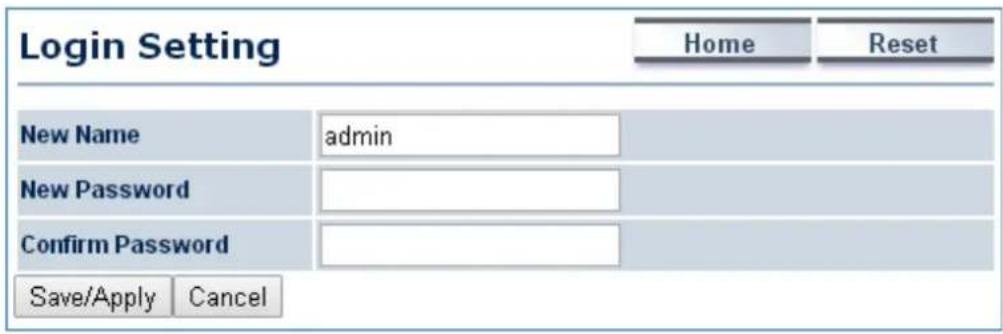
Figure 5-48 Administration (Password Settings)
The page includes the following settings:
| Object Description | |
| New Name | Enter a new username for logging in to the Web page. |
| New Password | Enter a new password for logging in to the Web page. |
| Confirm Password | Re-enter the new password for confirmation. |
| Save/Apply | Click Save/Apply to apply all changes. |
| Cancel | Click Cancel to cancel the settings. |
5.6.2 Management VLAN
Click "Management → Management VLAN" to configure the management VLAN settings.
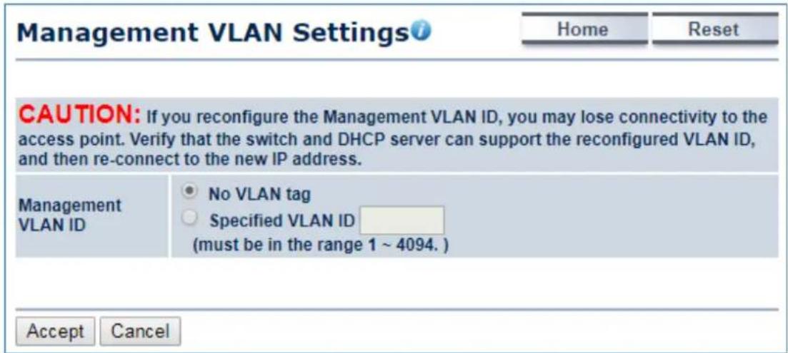
Figure 5-49 Management VLAN
The page includes the following settings:
| Object Description | |
| Management VLAN ID | If your network includes VLANs and if tagged packets need to pass through the Access Point, enter the VLAN ID. Otherwise, select No VLAN tag. |
| • Accept | Click Accept to apply the changes. |
| • Cancel | Click Cancel to cancel the settings. |
5.6.3 SNMP Settings
SNMP is used in network management systems to monitor network-attached devices for conditions that warrant administrative attention.
Click "Management → SNMP Settings" to configure SNMP settings.
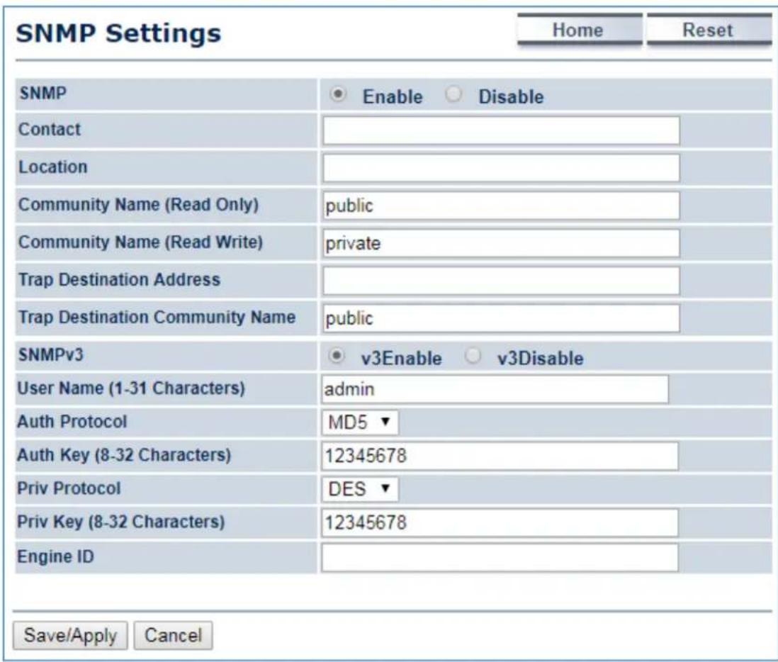
Figure 5-50 SNMP Settings
The page includes the following settings:
| Object Description | |
| • SNMP | Enable or disable the SNMP service. |
| • Contact | Enter the contact details of the device. |
| • Location | Enter the location of the device. |
| • Community Name (Read Only) | Enter the password for accessing the SNMP community for read-only access. |
| Community Name (Read/Write) | Enter the password for accessing the SNMP community for read and write access. |
| Trap Destination Address | Enter the IP address where SNMP traps are to be sent. |
| Trap Destination Community Name | Enter the password of the SNMP trap community. |
| SNMPv3 | Enable or Disable the SNMPv3 feature. |
| User Name | Specify the username for SNMPv3. |
| Auth Protocol | Select the authentication protocol type: MD5 or SHA. |
| Auth Key (8-32 Characters) | Specify the authentication key for authentication. |
| Priv Protocol | Select the privacy protocol type: DES. |
| Priv Key (8-32 Characters) | Specify the privacy key for privacy. |
| Engine ID | Specify the engine ID for SNMPv3. |
| Save/Apply | Click Save/Apply to apply all changes. |
| Cancel | Click Cancel to cancel the settings. |
5.6.4 Backup/Restore Settings
Click "Management → Backup/Restore Settings" and the following page will be displayed.
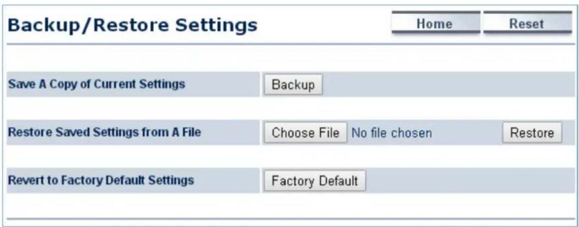
Figure 5-51 Backup/Restore Settings
The page includes the following settings:
| Object Description | |
| Save A Copy of Current Settings | Click Backup to save the current configured settings. |
| Restore Saved Settings from A File | To restore settings that have been previously backed up, click Choose File to select the file, and click Restore. |
| Revert to Factory Default Settings | Click Factory Default to restore the device to its factory default settings. |
5.6.5 Auto Reboot Settings
Click "Management → Auto Reboot Settings" and the following page will be displayed.
This page allows you to enable and configure system auto reboot interval. The device can regularly reboot according to the frequency in different time formats of interval.
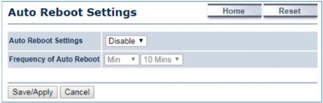
Figure 5-52 Auto Reboot Settings
The page includes the following settings:
| Object Description | |
| • Auto Reboot Settings | Select Enable from the drop-down menu to setup this function. |
| • Frequency of Auto Reboot | Select the frequency interval using the drop-down menus. The interval supported in different time formats:Min: 10/20/30/40/50/60 MinsHour: 1~24 hoursDay: 1~31 daysWeek: 1~5 weeks |
| • Save/Apply | Click Save/Apply to apply all changes. |
| • Cancel | Click Cancel to cancel the settings. |
5.6.6 Firmware Upgrade
Click "Management → Firmware Upgrade" to upgrade the device's firmware.
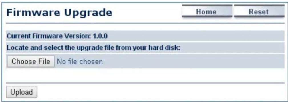
Figure 5-53 Firmware Upgrade
The page includes the following settings:
| Object Description | |
| • Current Firmware Version | Click ON to enable or click OFF to disable the option. |
| • Choose File | Click Choose File to locate and select the upgrade file from your local hard disk. |
| • Upload | Click Upload to upgrade the firmware. |
Firmware Upgrade Procedure
The following procedure will guide you to how to upgrade the firmware.
Step 1. Click the Choose File button to locate the firmware file path. Then, click the Upload button.
Step 2. The firmware checksum information appeared to help you confirm the file is correct. Once confirmed, click the Upgrade button to begin the upgrade process.
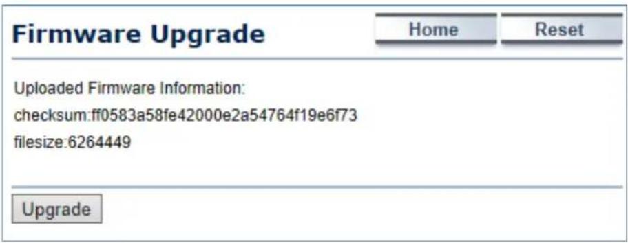
Step 3. Wait for the process to finish.
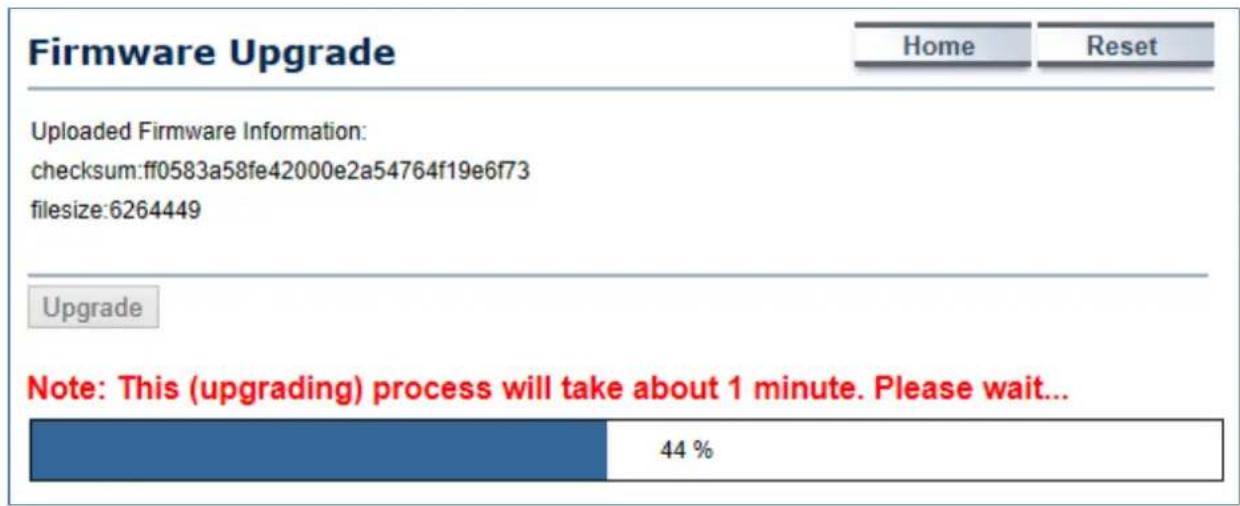
Step 4. When the upgrade is finished, the system will auto reboot and you can click the hyperlink "Click here when AP is ready" after the system restarts.
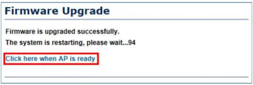
5.6.7 Time Settings
Click "Management → Time Settings" to configure time zone and NTP server settings to be in sync with the device's time.
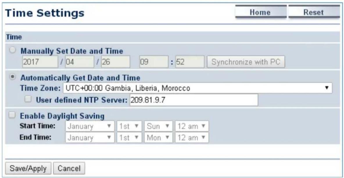
Figure 5-54 Time Settings
The page includes the following settings:
| Object Description | |
| • Manually Set Date and Time | Enter the date and time values in the date and time fields or click the Synchronize with PC to get the date and time values from the administrator's PC. |
| • Automatically Get Date and Time | Select a time zone from the drop-down list and check whether you want to enter the IP address of an NTP server or use the default NTP server. |
| • Enable Daylight Saving | Click to enable or disable daylight savings time. Select the start and stop times from the Start Time and Stop Time dropdown lists. |
| • Save/Apply | Click Save/Apply to apply all changes. |
| • Cancel | Click Cancel to cancel the settings. |
5.6.8 Wi-Fi Schedule
This page allows you to configure wireless schedule. The device can regularly enable/disable Wi-Fi function according to the pre-defined schedule rules.
Click "Management → Auto Reboot Settings" and the following page will be displayed.
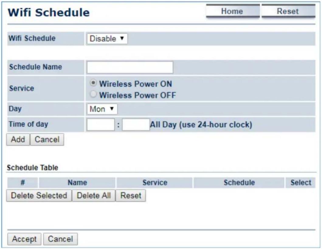
Figure 5-55 Wi-Fi Schedule
The page includes the following settings:
| Object Description | |
| Schedule Name | Enter the description of the schedule service. |
| Service | Select the type of schedule service, either Wireless Power ON or Wireless Power OFF. |
| Day | Select the days of the week to enable the schedule service. |
| Time of Day | Set the start time that the service is active. |
| Add | Click Add to append the schedule service to the schedule service table |
| Cancel | Click Cancel to discard changes. |
5.6.9 CLI Settings
The command line interface (CLI) allows user to access the device through a command console, modem or Telnet connection for configuration.
Click "Management → CLI Settings" to enable/disable CLI (Command Line Interface).
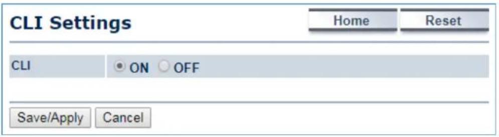
Figure 5-56 CLI Settings
The page includes the following settings:
| Object Description | |
| • CLI | Select ON/OFF to enable or disable the ability to modify the device via a command line interface (CLI). |
| • Save/Apply | Click Save/Apply to apply all changes. |
| • Cancel | Click Cancel to cancel the settings. |
5.6.10 Log
Click "Management → Log" to enable/disable system log.
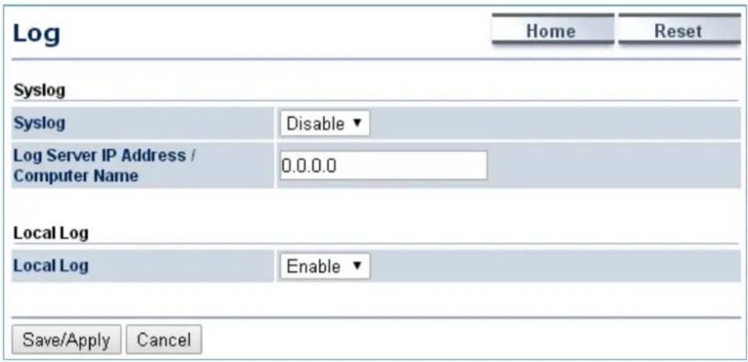
Figure 5-57 Log
The page includes the following settings:
| Object Description | |
| • Syslog | Enable or disable the syslog function. |
| • Log Server IP Address | Enter the IP address of the log server. |
| • Local Log | Enable or disable the local log service. |
| • Save/Apply | Click Save/Apply to apply all changes. |
| • Cancel | Click Cancel to cancel the settings. |
5.6.11 Diagnostics
Click "Management → Diagnostics" to test the connection and performance through the built-in diagnostics utilities.
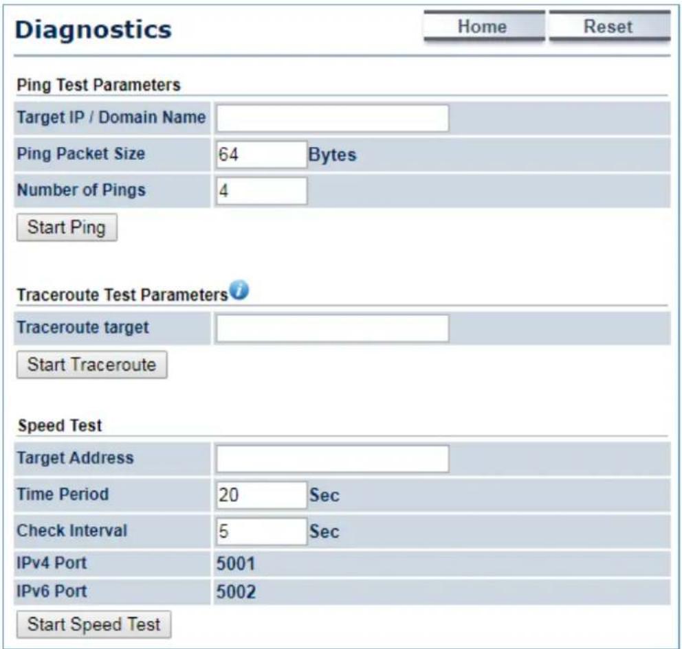
Figure 5-58 Diagnostics
The page includes the following settings:
| Object Description | |
| • Target IP / Domain Name | Enter the IP address you would like to search. |
| • Ping Packet Size | Enter the packet size of each ping. |
| • Number of Pings | Enter the number of times you want to ping. |
| • Start Ping | Click Start Ping to begin pinging. |
| • Trace route target | Enter an IP address or domain name you want to trace. |
| • Start Traceroute | Click Start Traceroute to begin the traceroute operation. |
| • Target Address | Enter the IP address of the target PC. |
| • Time period | Enter time period for the speed test. |
| • Check Interval | Enter the interval for the speed test. |
| • Start Speed Test | Click Start Speed Test to begin the speed test operation. |
| • IPv4 Port | Displays the IPv4 port number of the device. |
| • IPv6 Port | Displays the IPv6 port number of the device. |
5.6.12 Logout
Click "Management → Logout" to log out the system.
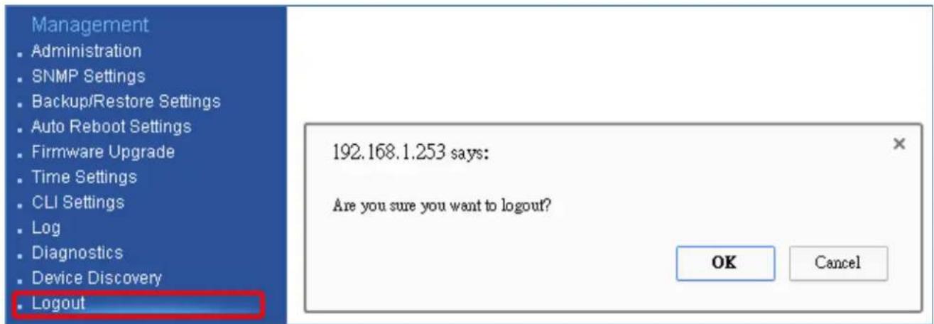
Figure 5-59 Logout
The page includes the following settings:
| Object Description | |
| • OK | Click OK to log out the system. |
| • Cancel | Click Cancel to cancel the operation. |
Appendix A: Troubleshooting
If you find the AP is working improperly or stop responding to you, please read this troubleshooting first before contacting the Planet Tech Support for help. Some problems can be solved by yourself within very short time.
| Scenario Solution | |
| The AP is not responding to me when I want to access it by web browser. | a. Please check the connection of the power cord and the Ethernet cable of this AP. All cords and cables should be correctly and firmly inserted to the AP.b. If all LEDs on this AP are off, please check the status of power adapter, and make sure it is correctly powered.c. You must use the same IP address section that AP uses.d. Are you using MAC or IP address filter? Try to connect the AP by another computer and see if it works; if not, please reset the AP to the factory default settings (Press the ‘reset’ button for over 10 seconds).e. Set your computer to static IP address, and see if the Planet Smart Discovery can find the AP or not.f. If you did a firmware upgrade and this happens, contact the Planet Tech Support for help.g. If all the solutions above don’t work, contact Planet Tech Support for help. |
| I can’t get connected to the Internet. | a. Check the Internet connection status from the router that is connected with the AP.b. Please be patient. Sometimes Internet is just that slow.c. If you have connected a computer to Internet directly before, try to do that again, and check if you can get connected to Internet with your computer directly attached to the device provided by your Internet service provider.d. Check PPPoE / L2TP / PPTP user ID and password in your router again.e. Call your Internet service provider and check if there’s something wrong with their service.f. If you just can’t connect to one or more website, but you can still use other internet services, please check URL/Keyword filter.g. Try to reset the AP and try again later.h. Reset the device provided by your Internet service provider.i. Try to use IP address instead of hostname. If you can use IP address to communicate with a remote server, but can’t use hostname, please check DNS setting. |
| I can’t locate my AP by my wireless device. | a. ‘Broadcast ESSID’ set to off?b. The antenna is properly secured.c. Are you too far from your AP? Try to get closer.d. Please remember that you have to input ESSID on your wireless client manually, if ESSID broadcast is disabled. |
| File downloading is very slow or breaks frequently. | a. Are you using QoS function? Try to disable it and try again.b. Internet is slow sometimes; try to be patient.c. Try to reset the AP and see if it's better after that.d. Try to know what computers do on your local network. If someone's transferring big files, other people will think Internet is really slow.e. If this never happens before, call you Internet service provider to know if there is something wrong with their network. |
| I can't log in to the web management interface; the password is wrong. | a. Make sure you're connecting to the correct IP address of the AP.b. Password is case-sensitive. Make sure the 'Caps Lock' light is not illuminated.c. If you really forget the password, do a hard reset. |
| The AP becomes hot | a. This is not a malfunction, if you can keep your hand on the AP's case.b. If you smell something wrong or see the smoke coming out from AP or A/C power adapter, please disconnect the AP and A/C power adapter from utility power (make sure it's safe before doing this!), and call your dealer for help. |
Appendix B: Use Planet Smart Discovery to find AP
To easily discover the WAP-200N/WBS-200N in your Ethernet environment, the Planet Smart Discovery Utility is an ideal solution. The utility is available at: http://www.planet.com.tw/en/product/images/48590/Planet_Utility.zip
The following instructions will guide you to how to use the Planet Smart Discovery Utility.
Step 1. Download the Planet Smart Discovery Utility in administrator PC.
Step 2. Execute this utility.

Planet_Utility.exe PLANET Corp.
Step 3. Click the "Refresh" button as shown below to update the list of the currently connected devices.
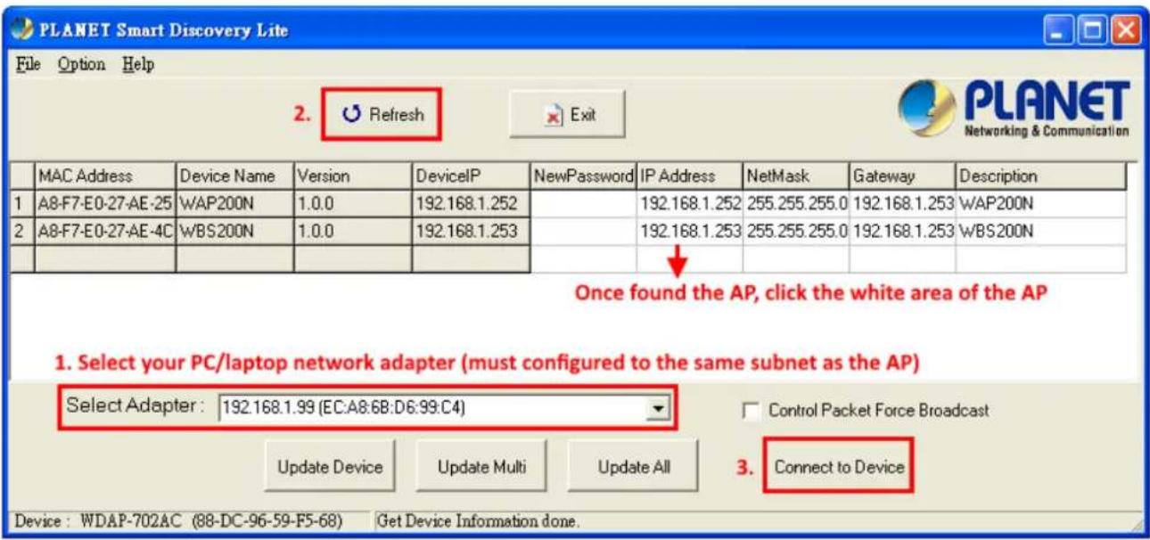
Figure B-1 PLANET Smart Discovery
Step 4. Select the AP from the list and then click the “Connect to Device” button to link to the Web Management Configuration page.

The fields in white background can be modified directly, and then you can apply the new setting by clicking the "Update Device" button.
Appendix C: FAQ
Q1: How to set up the AP Client Connection
Topology:
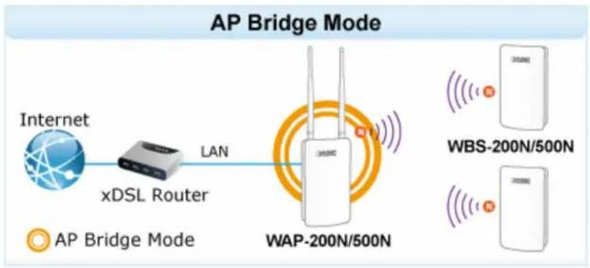
flowchart
graph LR
    A["Internet"] -->|LAN| B["xDSL Router"]
    B --> C["WAP-200N/500N"]
    D["AP Bridge Mode"] --> E["WBS-200N/500N"]
    F["AP Bridge Mode"] --> G["WBS-200N/500N"]
- Use static IP in the PCs that are connected with AP-1 (Site-1) and AP-2 (Site-2). In this case, Site-1 is "192.168.1.100", and Site-2 is "192.168.1.200".
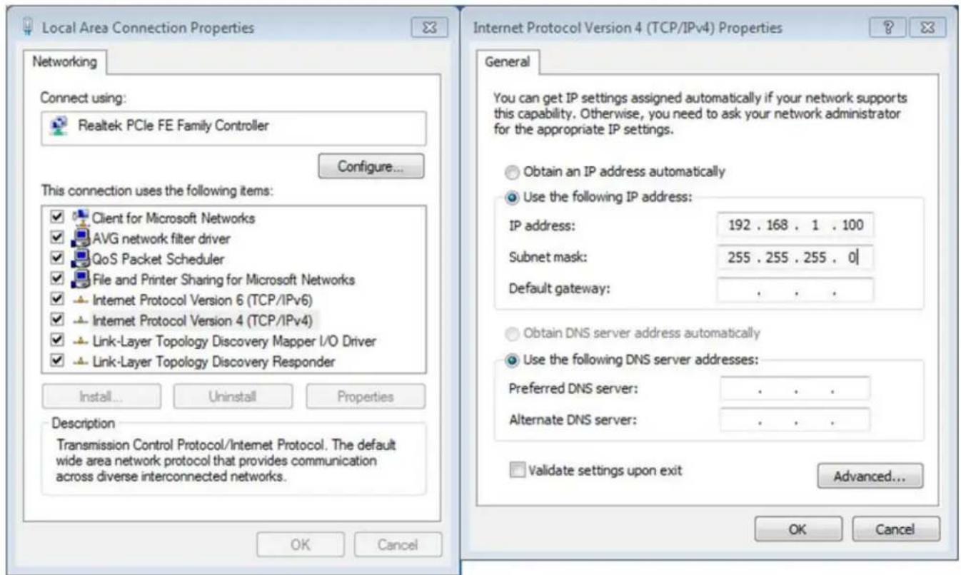
- In the AP-1, go to "System->IP Settings" to configure the IP address to static and different from the CPE.
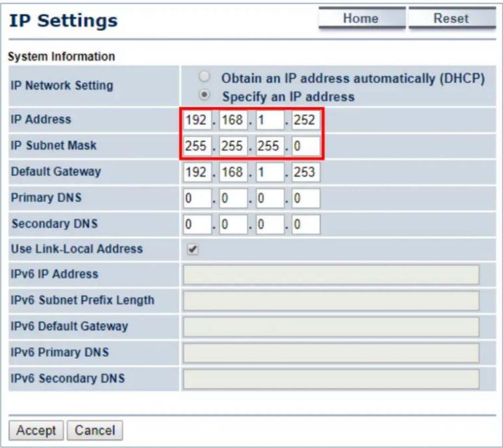
- In the AP-1, go to "System->Operation Mode" and set it to use "Access Point" mode. Then, click "Save & Apply".
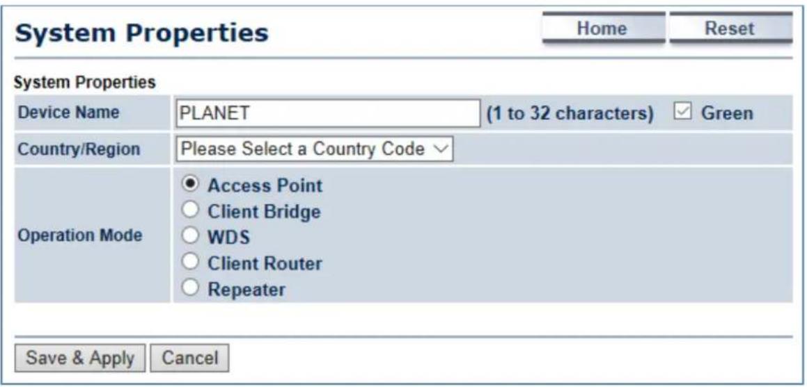
- In the AP-1, go to "Wireless-> Wireless Network" to configure channel and click "Edit" for security setting.
(1) Channel HT Mode: set to "40MHz" for wider bandwidth
(2) Channel/Frequency: uncheck "Auto" and set to a fixed channel
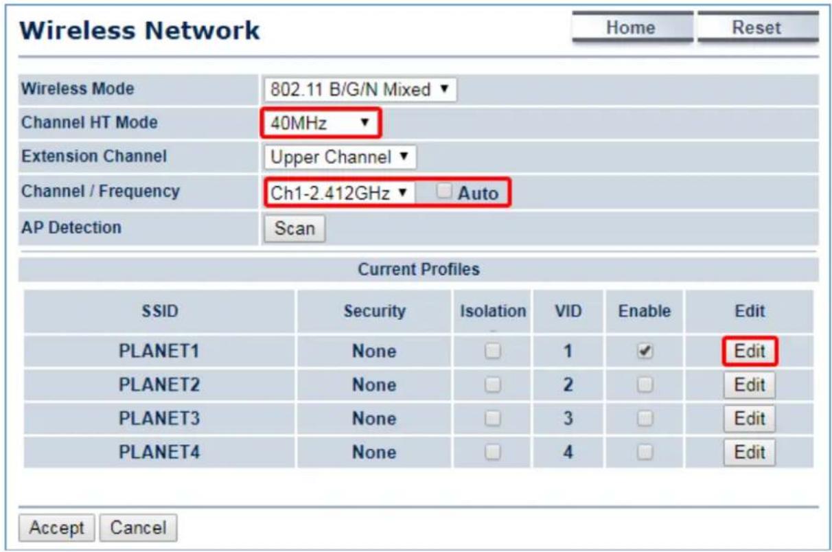
- In the SSID Profile, you can configure your own SSID and Passphrase. Then, click "Save" to go back to the main page.
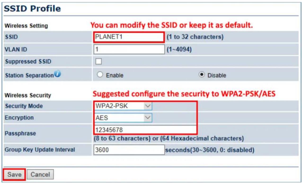
- Click "Accept" to save the configurations.
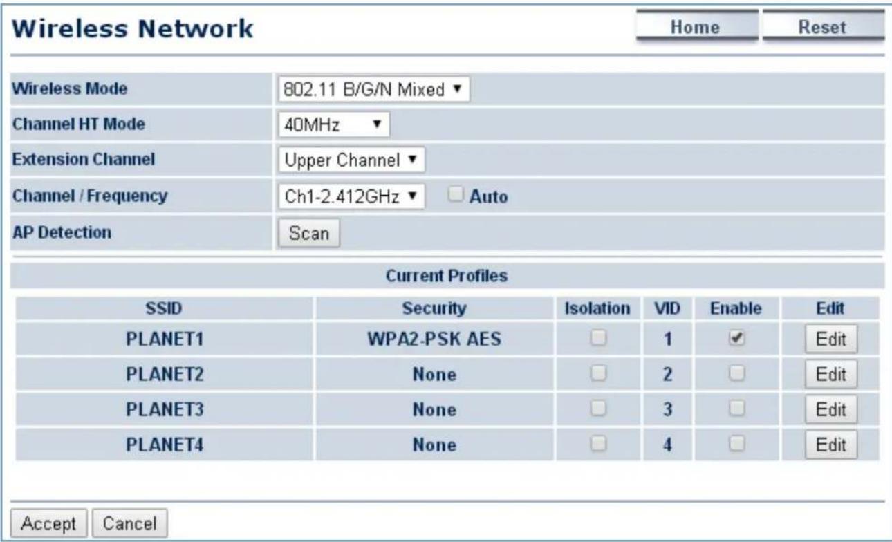
- Go to the "Status->Save/Reload" page to click "Save & Apply" to force the AP to reboot so that it can apply all configurations and take effect.
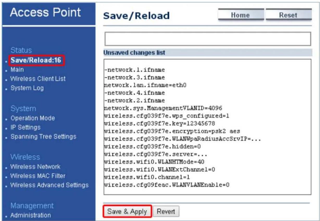
- In the AP-2, go to "System->IP Settings" to configure the IP address to static and different from the CPE.
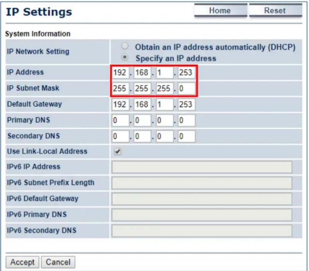
- In the AP-2, go to "System->Operation Mode" and set it to use "Client Bridge" mode. Then, click "Save & Apply".
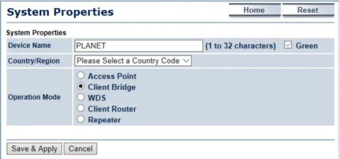
- In the AP-2, go to "Wireless-> Wireless Network". Click "Site Survey" to discover the AP-1.
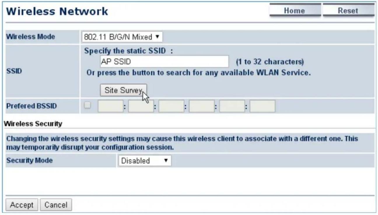
- Click the AP-1 to let the AP-2 to connect it. Then, it will go back to the main page.
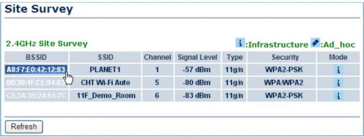
- Click the check box of the preferred BSSID and configure the encryption to be the same as the AP-1. Then, click "Accept" to save the configurations.
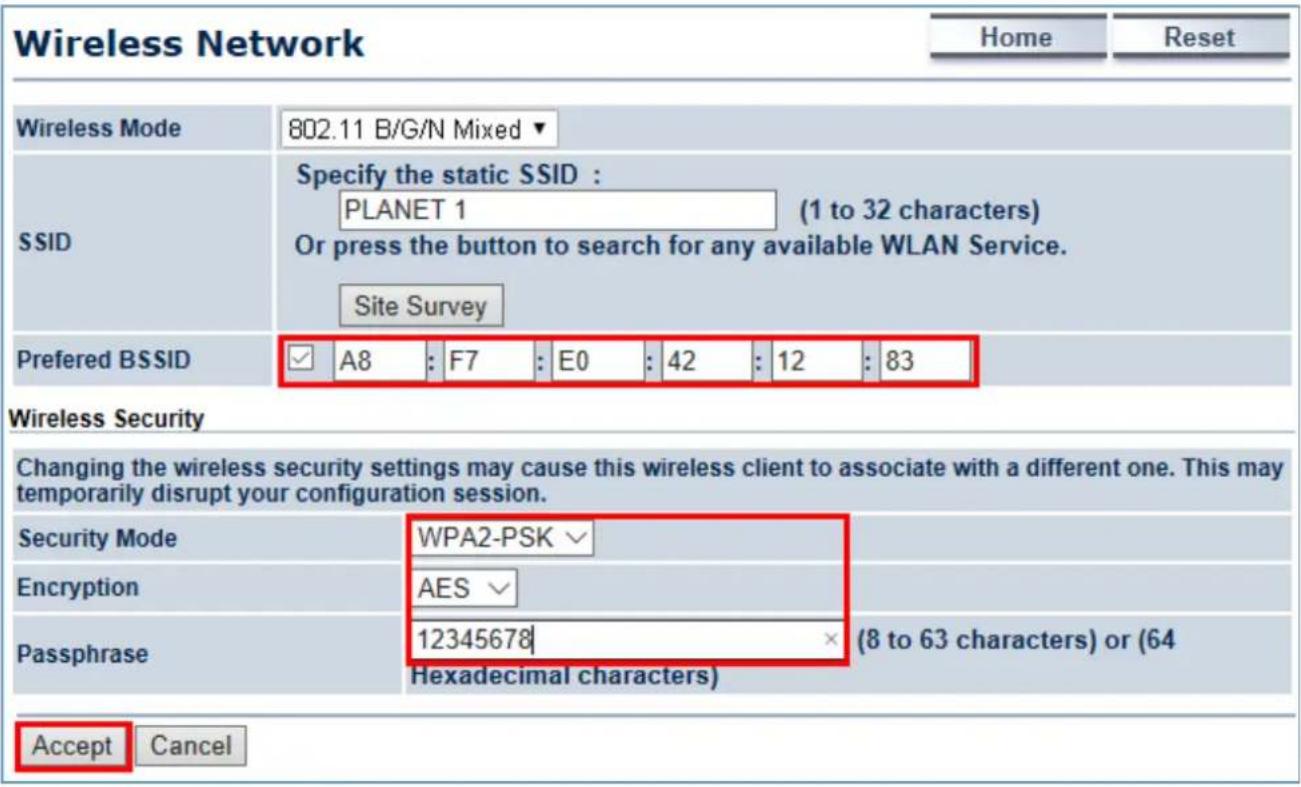
- Go to the "Status->Save/Reload" page to click "Save & Apply" to force the AP to reboot so that it can apply all configurations and take effect.
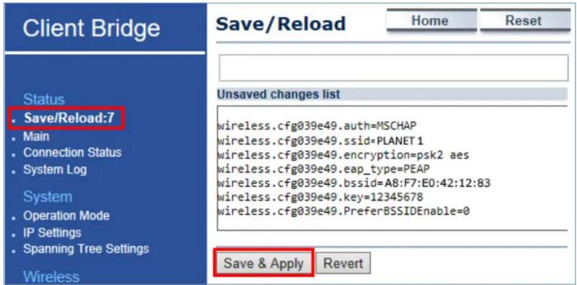
- In the AP-2, go to the "Status->Connection Status" page to check whether the AP-2 is associated to the AP-1 successfully.
| Connection Status | Home | Reset | |
| Network Type | Client Bridge | ||
| SSID | PLANET1 | ||
| BSSID | A8:F7:E0:42:12:83 | ||
| Connection Status | Associated | ||
| Wireless Mode | IEEE 802.11B/G/N Mixed | ||
| Current Channel | 2.412 GHz(Channel 1) | ||
| Security | WPA2-PSK AES | ||
| Tx Data Rates(Mbps) | 300 Mbps | ||
| Current noise level | -95 dBm | ||
| Signal strength | -60 dBm | ||
| Refresh | |||
- In the AP-1, go to the "Status-> Wireless Client List" page to check the client's signal strength.
| Client List | Home | Reset | |||
| SSID:# | MAC Address | TX(Bytes) | RX(Bytes) | RSSI(dBm) | Kick and Ban |
| SSID1:#1 | a8:f7:e0:2f:83:57 | 45345Kb | 45993Kb | -27 | Kick |
| Refresh | |||||
- Use command line tool to ping each other to ensure the link is successfully established.
For example, from Site-1, ping 192.168.1.200; and at Site-2, ping 192.168.1.100.
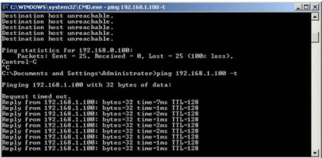

Attention should be paid to the following hints:
1) The encryption method must be the same at both sites if configured.
2) Both sites should be Line-of-Sight.
3) Included in the package are two 5dBi antennas for the WAP-200N only for long distance over 1km. Please connect to the 2.4GHz antennas with higher gain.
4) For PtP connection over 1km, please adjust "Distance" setting to the actual distance between both sites on the 'both sites' setting page.
5) To adjust "Transmit Power", please:
(a) Go to the "Operation Mode" page to disable the "Green" option.
(b) Go to "Wireless Advanced Settings-> Transmit Power" to manually adjust the transmit power.
Q2: How to set up the WDS Connection
Topology:
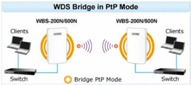
flowchart
graph LR
    A["Clients"] --> B["Switch"]
    B --> C["WBS-200N/500N"]
    C --> D["Bridge PtP Mode"]
    D --> E["Clients"]
    E --> F["Switch"]
    F --> G["WBS-200N/500N"]
    G --> H["Bridge PtP Mode"]
    H --> I["Clients"]
    I --> J["Switch"]
    J --> K["WBS-200N/500N"]
    K --> L["Bridge PtP Mode"]
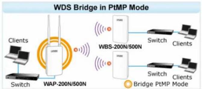
flowchart
graph LR
    A["Clients"] --> B["Switch"]
    B --> C["WAP-200N/500N"]
    C --> D["Wireless Interface"]
    D --> E["WBS-200N/500N"]
    E --> F["Switch"]
    F --> G["Clients"]
    E --> H["Switch"]
    H --> I["Clients"]
    J["Bridge PtMP Mode"] --> K["Wireless Interface"]
    K --> L["WAP-200N/500N"]
    L --> M["Wireless Interface"]
    M --> N["WBS-200N/500N"]
- Use static IP in the PCs that are connected with WBS-200N-1 (Site-1) and WBS-200N-2 (Site-2). In this case, Site-1 is "192.168.1.100", and Site-2 is "192.168.1.200".
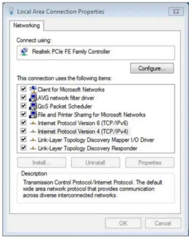
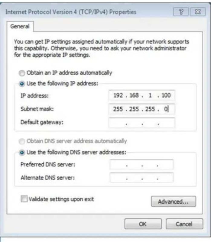
- In the AP-1, go to "System->IP Settings" to configure the IP address to static and different from the CPE.
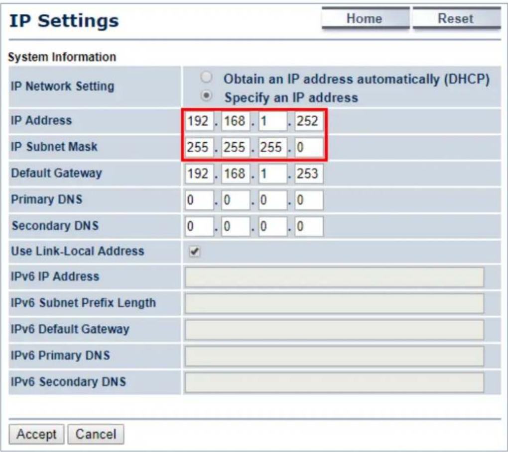
- In the AP-1, go to "System->Operation Mode" and set it to use "WDS Access Point" mode. Then, click "Save & Apply".
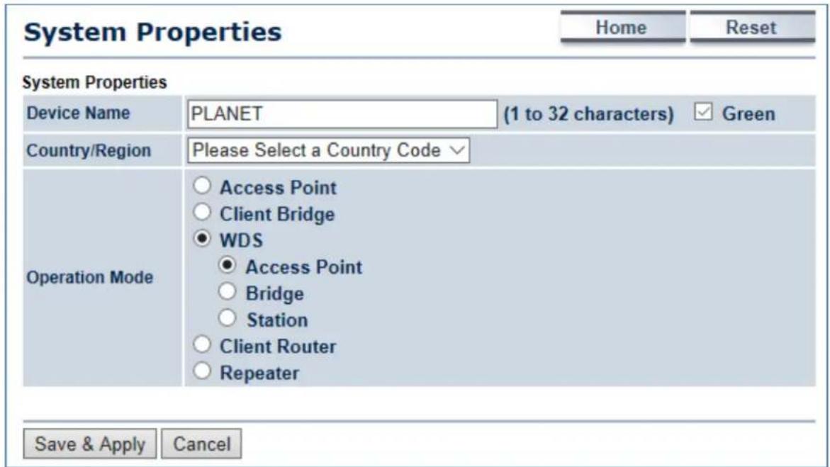
- In the AP-1, go to "Wireless-> Wireless Network" to configure channel and click "Edit" for security setting.
(1) Channel HT Mode: set to "40MHz" for wider bandwidth
(2) Channel/Frequency: uncheck "Auto" and set to a fixed channel
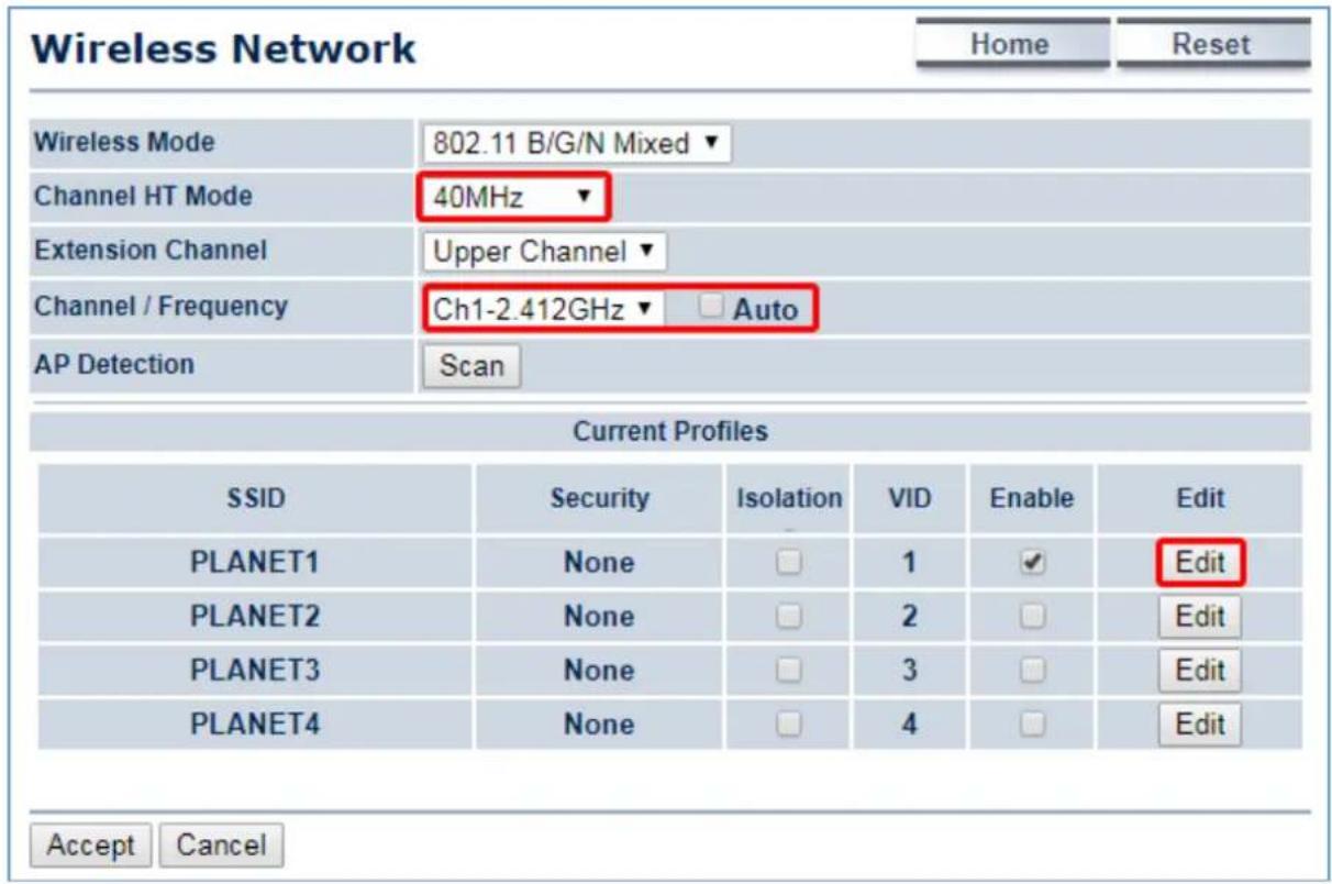
- In the SSID Profile, you can configure your own SSID and Passphrase. Then, click "Save" to go back to the main page.
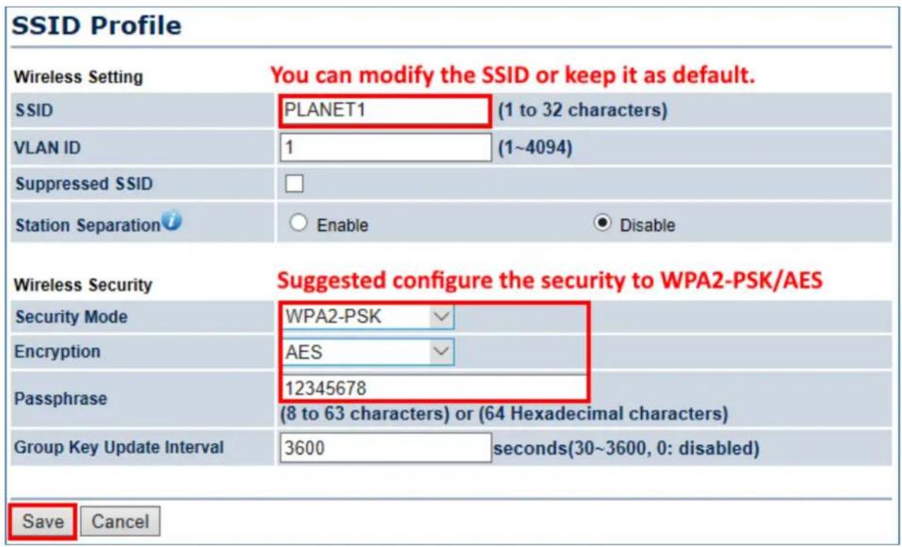
- Click "Accept" to save the configurations.
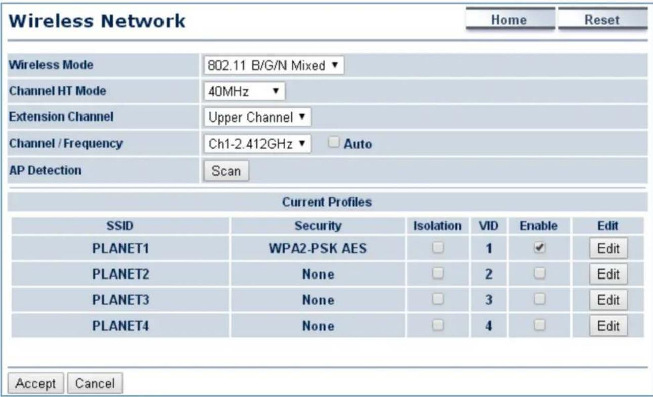
- Go to the "Status->Save/Reload" page to click "Save & Apply" to force the AP to reboot so that it can apply all configurations and take effect.
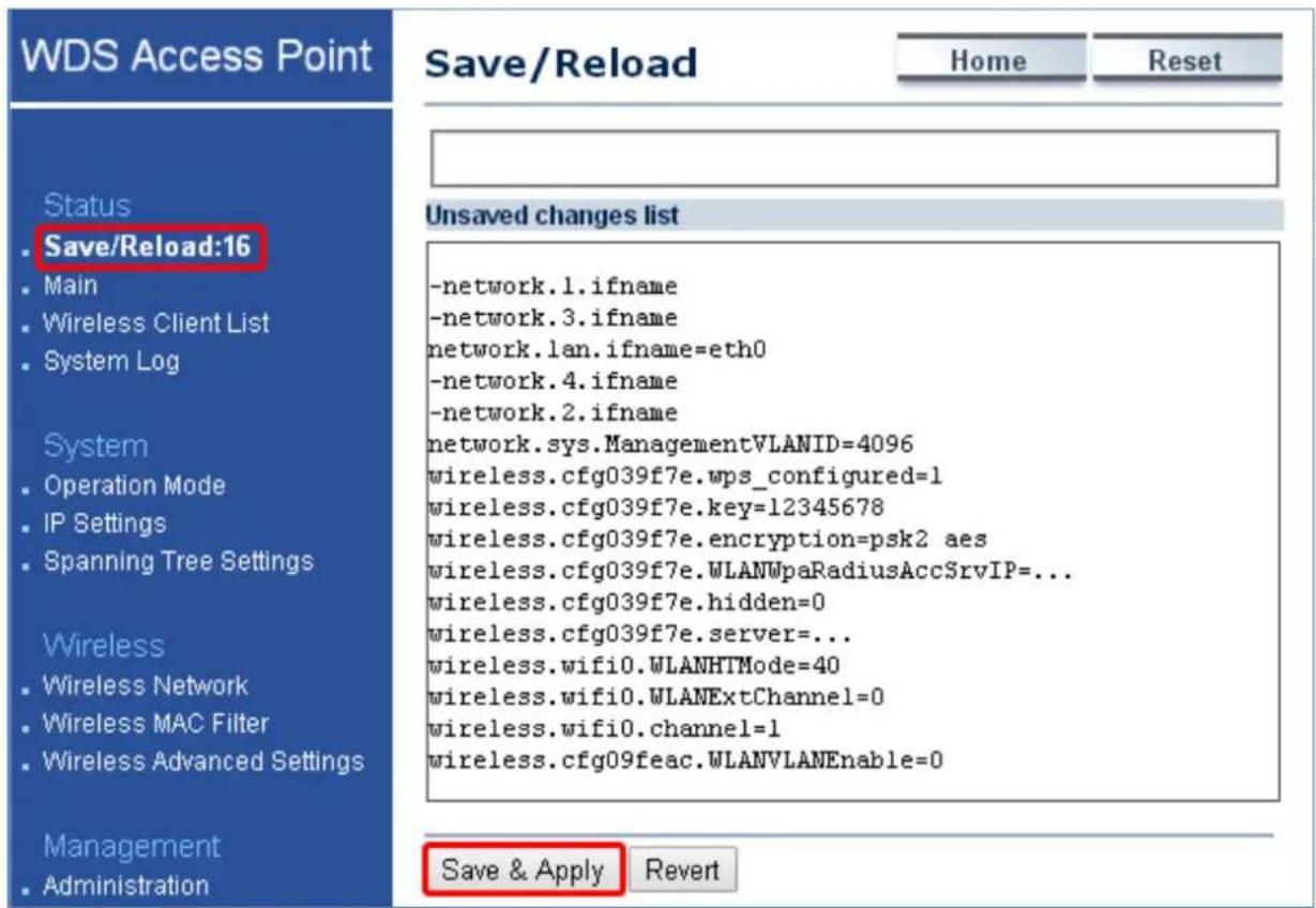
- In the AP-2, go to "System->IP Settings" to configure the IP address to static and different from the CPE.
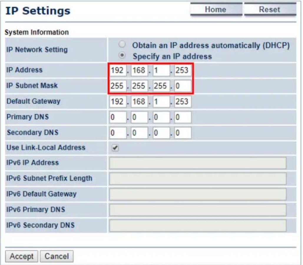
- In the AP-2, go to "System->Operation Mode" and set it to use "WDS Station" mode. Then, click "Save & Apply".
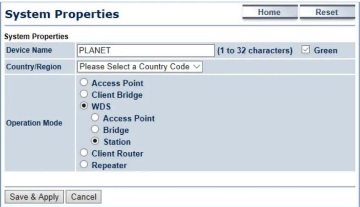
- In the AP-2, go to "Wireless-> Wireless Network". Click "Site Survey" to discover the AP-1.
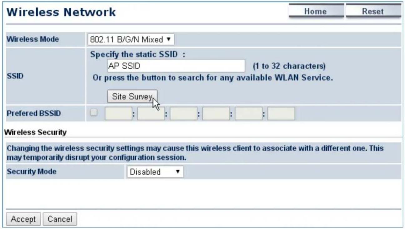
- Click the AP-1 to let the AP-2 connect it. Then, it will go back to the main page.
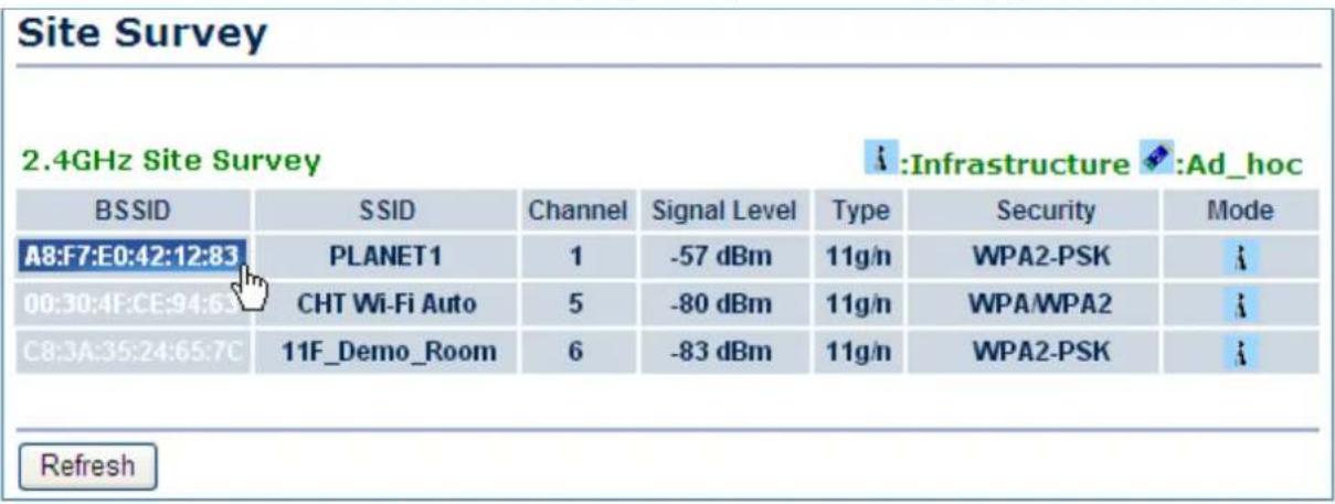
- Click the check box of the preferred BSSID and configure the encryption to be the same as the AP-1. Then, click "Accept" to save the configurations.
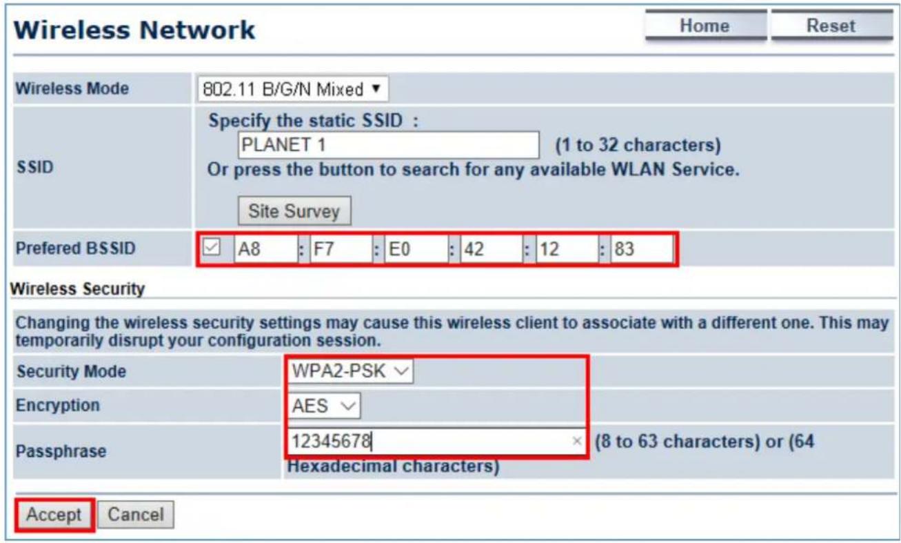
- Go to the "Status-> Save/Reload" page to click "Save & Apply" to force the AP to reboot so that it can apply all configurations and take effect.
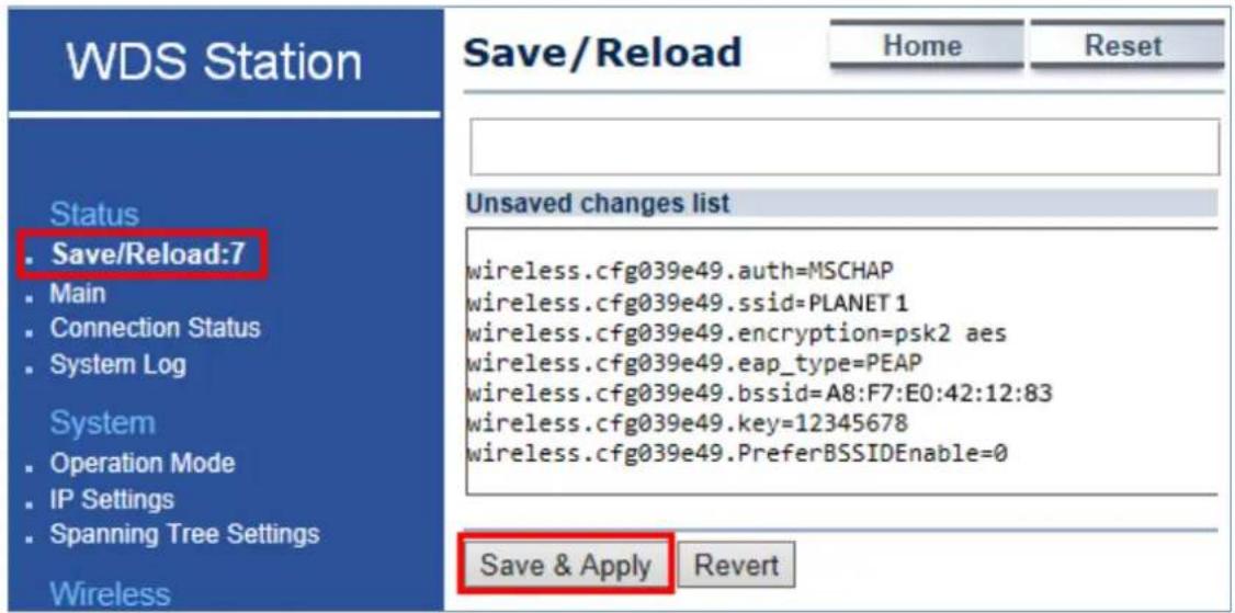
- In the AP-2, go to the "Status->Connection Status" page to check whether the AP-2 is associated with the AP-1 successfully.
| Connection Status | Home | Reset | |
| Network Type | WDS Station | ||
| SSID | PLANET1 | ||
| BSSID | A8:F7:E0:42:12:83 | ||
| Connection Status | Associated | ||
| Wireless Mode | IEEE 802.11B/G/N Mixed | ||
| Current Channel | 2.412 GHz(Channel 1) | ||
| Security | WPA2-PSK AES | ||
| Tx Data Rates(Mbps) | 300 Mbps | ||
| Current noise level | -95 dBm | ||
| Signal strength | -60 dBm | ||
| Refresh | |||
- In the AP-1, go to the "Status-> Wireless Client List" page to check the client's signal strength.
| Client List | Home | Reset | |||
| SSID:# | MAC Address | TX(Bytes) | RX(Bytes) | RSSI(dBm) | Kick and Ban |
| SSID1:#1 | a8:f7:e0:2f:83:57 | 45345Kb | 45993Kb | -27 | Kick |
| Refresh | |||||
- Use command line tool to ping each other to ensure the link is successfully established.
For example, from Site-1, ping 192.168.1.200; and at Site-2, ping 192.168.1.100.
| Destination host unreachable. |
| Destination host unreachable. |
| Destination host unreachable. |
| Destination host unreachable. |
| Destination host unreachable. |
| Ping statistics for 192.168.0.100: Packets: Sent = 25, Received = 0, Lost = 25 (100% loss), Control-C ^C C:\Documents and Settings\Administrator>ping 192.168.1.100 -t |
| Pinging 192.168.1.100 with 32 bytes of data: |
| Request timed out. Reply from 192.168.1.100: bytes=32 time=7ns TTL=128 Reply from 192.168.1.100: bytes=32 time=1ns TTL=128 Reply from 192.168.1.100: bytes=32 time=2ns TTL=128 Reply from 192.168.1.100: bytes=32 time=1ns TTL=128 Reply from 192.168.1.100: bytes=32 time=2ns TTL=128 Reply from 192.168.1.100: bytes=32 time=2ns TTL=128 Reply from 192.168.1.100: bytes=32 time=1ns TTL=128 Reply from 192.168.1.100: bytes=32 time=1ns TTL=128 |

Attention should be paid to the following hints:
1) The encryption method must be the same at both sites if configured.
2) Both sites should be Line-of-Sight.
3) Included in the package are two 5dBi antennas for the WAP-200N only for long distance over 1km. Please connect to the 2.4GHz antennas with higher gain.
4) For PtP connection over 1km, please adjust "Distance" setting to the actual distance between both sites on the 'both sites' setting page.
5) To adjust "Transmit Power", please:
(a) Go to the "Operation Mode" page to disable the "Green" option.
(b) Go to the "Wireless Advanced Settings-> Transmit Power" to manually adjust the transmit power.
EC Declaration of Conformity
| English | Hereby, PLANET Technology Corporation, declares that this 300Mbps 802.11n Wireless Outdoor AP/CPE is in compliance with the essential requirements and other relevant provisions of Directive 1999/5/EC. | Lietuviškai | Šiuo PLANET Technology Corporation,, skelbia, kad 300Mbps 802.11n Wireless Outdoor AP/CPE tenkina visus svarbiausius 1999/5/EC direktyvos reikalavimus ir kitas svarbias nuostatas. |
| Česky | Společnost PLANET Technology Corporation, tímto prohlašuje, že tato 300Mbps 802.11n Wireless Outdoor AP/CPE splňuje základní požadavky a další příslušná ustanovení směrnice 1999/5/EC. | Magyar | A gyártó PLANET Technology Corporation, kijelenti, hogy ez a 300Mbps 802.11n Wireless Outdoor AP/CPE megfelel az 1999/5/EK irányelv alapkövetelményeinek és a kapcsolódó rendelkezéseknek. |
| Dansk | PLANET Technology Corporation, erklærer herved, at følgende udstyr 300Mbps 802.11n Wireless Outdoor AP/CPE overholder de væsentlige krav og øvrige relevante krav i direktiv 1999/5/EF | Malti | Hawnhekk, PLANET Technology Corporation, jiddikjara li dan 300Mbps 802.11n Wireless Outdoor AP/CPE jikkonforma mal-ħtiġijiet essenzjali u ma provvedimenti oħrajn relevanti li hemm fid-Dirrettiva 1999/5/EC |
| Deutsch | Hiermit erklärt PLANET Technology Corporation, dass sich dieses Gerät 300Mbps 802.11n Wireless Outdoor AP/CPE in Übereinstimmung mit den grundlegenden Anforderungen und den anderen relevanten Vorschriften der Richtlinie 1999/5/EG befindet". (BMWi) | Nederlands | Hierbij verklaart , PLANET Technology orporation, dat 300Mbps 802.11n Wireless Outdoor AP/CPE in overeenstemming is met de essentiële eisen en de andere relevante bepalingen van richtlijn 1999/5/EG |
| Eestikeele s | Kăesolevaga kinnitab PLANET Technology Corporation, et see 300Mbps 802.11n Wireless Outdoor AP/CPE vastab Euroopa Nõukogu direktiivi 1999/5/EC põhinõuetele ja muudele olulistele tingimustele. | Polski | Niniejszym firma PLANET Technology Corporation, oświadcza, že 300Mbps 802.11n Wireless Outdoor AP/CPE spełnia wszystkie istotne wymogi i klauzule zawarte w dokumencie „Directive 1999/5/EC”. |
| Ελληνικά | ME THN ΠΑΡΟΥΣΑ , PLANET Technology Corporation, ΔΗΛΩΝΕΙ OTI AYTO 300Mbps 802.11n Wireless Outdoor AP/CPE ΣΥΜΜΟΡΦΩΝΕΤΑΙ ΠΡΟΣ ΤΙΣ ΟΥΣΙΩΔΕΙΣ ΑΠΑΙΤΗΣΕΙΣ ΚΑΙ ΤΙΣ ΛΟΙΠΕΣ ΣΧΕΤΙΚΕΣ ΔΙΑΤΑΞΕΙΣ ΤΗΣ ΟΔΗΓΙΑΣ 1999/5/EK | Português | PLANET Technology Corporation, declara que este 300Mbps 802.11n Wireless Outdoor AP/CPE está conforme com os requisitos essenciais e outras disposições da Directiva 1999/5/CE. |
| Español | Por medio de la presente, PLANET Technology Corporation, declara que 300Mbps 802.11n Wireless Outdoor AP/CPE cumple con los requisitos esenciales y cualesquiera otras disposiciones aplicables o exigibles de la Directiva 1999/5/CE | Slovensky | Výrobca PLANET Technology Corporation, týmto deklaruje, že táto 300Mbps 802.11n Wireless Outdoor AP/CPE je v súlade so základnymi požiadavkami a ďalšími relevantnými predpismi smernice 1999/5/EC. |
| Français | Par la présente, PLANET Technology Corporation, déclare que les appareils du 300Mbps 802.11n Wireless Outdoor AP/CPE sont conformes aux exigences essentielles et aux autres dispositions pertinentes de la directive 1999/5/CE | Slovensko | PLANET Technology Corporation, s tem potrjuje, da je ta 300Mbps 802.11n Wireless Outdoor AP/CPE skladen/a z osnovnimi zahtevami in ustreznimi določili Direktive 1999/5/EC. |
| Italiano | Con la presente , PLANET Technology Corporation, dichiara che questo 300Mbps 802.11n Wireless Outdoor AP/CPE è conforme ai requisiti essenziali ed alle altre disposizioni pertinenti stabilite dalla direttiva 1999/5/CE. | Suomi | PLANET Technology Corporation, vakuuttaa täten että 300Mbps 802.11n Wireless Outdoor AP/CPE typpinen laite on direktiivin 1999/5/EY oleellisten vaatimusten ja sită koskevien direktiivin muiden ehtojen mukainen. |
| Latviski | Ar šo PLANET Technology Corporation, apliecina, ka šť 300Mbps 802.11n Wireless Outdoor AP/CPE atbilst Direktivas 1999/5/EK pamatprasībām un citiem atbilstošiem noteikumiem. | Svenska | Härmed intygar, PLANET Technology Corporation, att denna 300Mbps 802.11n Wireless Outdoor AP/CPE stár i överensstämmelse med de väsentliga egenskapskrav och övriga relevanta bestämmelser som framgår av direktiv 1999/5/EG. |
- 300Mbps 802.11n Outdoor Wireless AP/CPE
- Copyright
- FCC Interference Statement
- FCC Caution:
- FCC Radiation Exposure Statement
- CE Compliance Statement
- Safety
- WEEE regulation
- Revision
- CONTENTS
- Chapter 1.Product Introduction....7
- Chapter 2.Hardware Installation....14
- Chapter 3. Connecting to the AP .... 18
- Chapter 4. Quick Installation Guide ...... 22
- Chapter 5.Configuring the AP....27
- Status....49
- System....56
- Router (WISP Mode Only)....58
- Wireless....68
- Management 85
- Appendix A: Troubleshooting....96
- Appendix B: Use Planet Smart Discovery to find AP 98
- Appendix C: FAQ....99
- FIGURES
- Chapter 1. Product Introduction
- Package Contents
- Product Description
- Cost-effective Wireless Solution with Superior Performance
- Designed for Various Requirements
- Multiple SSIDs with VLAN Tagging
- Flexible and Reliable Outdoor Characteristics
- Advanced Security and Rigorous Authentication
- Easy Deployment and Management
- Product Features
- Industrial Compliant Wireless LAN
- Fixed Network Broadband Router
- RF Interface Characteristics
- Outdoor Environmental Characteristics
- Multiple Operation Modes and Wireless Features
- ▶ Secure Network Connection
- Easy Installation and Management
- Chapter 2. Hardware Installation
- Hardware Description
- Rear Panel – LED
- The Bottom Panel
- Bottom Panel
- PoE Warning Label
- Hardware Interface Definition
- Chapter 3. Connecting to the AP
- Preparation before Installation
- Professional Installation Required
- Safety Precautions
- Installation Precautions
- OUTDOOR INSTALLATION WARNING
- IMPORTANT SAFETY PRECAUTIONS:
- TO AVOID FALLING, USE SAFE PROCEDURES WHEN WORKING AT HEIGHTS ABOVE GROUND.
- IF A PERSON COMES IN CONTACT WITH ELECTRICAL POWER, AND CANNOT MOVE:
- Installing the AP
- Step 1. PoE and LAN port connection:
- Step 3. Pole Mounting:
- Step 4. Wall Mounting:
- Chapter 4. Quick Installation Guide
- Manual Network Setup -- TCP/IP Configuration
- Configuring the IP Address Manually
- Summary:
- Starting Setup in the Web UI
- Operation Mode
- Access Point (AP)
- Client Bridge (CB)
- WDS Access Point (WDS AP)
- WDS Station (WDS STA)
- WDS Bridge (WDS PtP/WDS PtMP)
- WDS Link Settings
- AES is strongly recommended
- Client Router (CR/WISP)
- Repeater
- Site Survey
- Status
- Main
- Save/Reload
- Wireless Client List
- WDS Link List
- DHCP Client Table
- Connection Status
- System Log
- System
- IP Settings
- Spanning Tree Settings (STP)
- Router (WISP Mode Only)
- DHCP Server Settings
- WAN Settings
- DHCP
- Static IP
- PPPoE
- PPTP
- VPN Pass Through
- Port Forwarding
- Name Protocol Start Port End Port Server IP Address Enable Modify Delete
- DMZ Settings
- Wireless
- Wireless Network
- WDS Link Settings
- NOTE:
- Security Settings
- ■ Disabled
- ■ WEP
- WPA-PSK
- WPA2-PSK
- ■ WPA-PSK Mixed
- ■ WPA (WPA Enterprise)
- ■ WPA2 (WPA2 Enterprise)
- ■ WPA Mixed (WPA Mixed Enterprise)
- Wireless MAC Filter
- Wireless Advanced Settings
- Management
- Administration (Password Settings)
- Management VLAN
- SNMP Settings
- Backup/Restore Settings
- Auto Reboot Settings
- Firmware Upgrade
- Firmware Upgrade Procedure
- Time Settings
- Wi-Fi Schedule
- Name Service Schedule Select
- CLI Settings
- Log
- Diagnostics
- Logout
- Appendix A: Troubleshooting
- Appendix B: Use Planet Smart Discovery to find AP
- Step 1. Download the Planet Smart Discovery Utility in administrator PC.
- Step 2. Execute this utility.
- Step 3. Click the "Refresh" button as shown below to update the list of the currently connected devices.
- Step 4. Select the AP from the list and then click the “Connect to Device” button to link to the Web Management Configuration page.
- Appendix C: FAQ
- Q1: How to set up the AP Client Connection
- Attention should be paid to the following hints:
- Q2: How to set up the WDS Connection
Brand : Planet
Model : WBS-200N
Category : Access Point