
TLP Pro 320C - Remote control Extron - Free user manual and instructions
Find the device manual for free TLP Pro 320C Extron in PDF.


| Product Type | Touch Panel Remote Control |
| Brand | Extron |
| Model | TLP Pro 320C |
| Display Size | 3.2 inches |
| Dimensions (H x W x D) | 3.5 x 2.5 x 1.0 inches (approx.) |
| Weight | 0.5 lbs (approx.) |
| Power Supply | PoE (Power over Ethernet) or 12V DC adapter |
| Primary Functions | Control AV systems, touch screen interface, customizable buttons |
| Resolution | 480 x 272 pixels |
| Connectivity | Ethernet, USB |
| Mounting | Wall mount or desk stand (optional) |
| Operating Temperature | 32°F to 104°F (0°C to 40°C) |
| Storage Temperature | -4°F to 140°F (-20°C to 60°C) |
| Humidity | 10% to 90% non-condensing |
| Warranty | 3 years (parts and labor) |
| Included Accessories | Power supply, mounting bracket, quick start guide |
| Compatible Software | Extron Global Configurator |
| Languages Supported | English, French, German, Spanish, Chinese |
| Firmware Updates | Via Ethernet or USB |
| Certifications | CE, FCC Class A, RoHS |
Frequently Asked Questions - TLP Pro 320C Extron
User questions about TLP Pro 320C Extron
0 question about this device. Answer the ones you know or ask your own.
Ask a new question about this device
Download the instructions for your Remote control in PDF format for free! Find your manual TLP Pro 320C - Extron and take your electronic device back in hand. On this page are published all the documents necessary for the use of your device. TLP Pro 320C by Extron.
USER MANUAL TLP Pro 320C Extron
Safety Instructions • English
WARNING: This symbol, ⚠, when used on the product, is intended to alert the user of the presence of uninsulated dangerous voltage within the product's enclosure that may present a risk of electric shock.
ATTENTION: This symbol, △, when used on the product, is intended to alert the user of important operating and maintenance (servicing) instructions in the literature provided with the equipment.
For information on safety guidelines, regulatory compliances, EMI/EMF compatibility, accessibility, and related topics, see the Extron Safety and Regulatory Compliance Guide, part number 68-290-01, on the Extron website, www.extron.com.
This equipment has been tested and found to comply with the limits for a Class A digital device, pursuant to part 15 of the FCC rules. The Class A limits provide reasonable protection against harmful interference when the equipment is operated in a commercial environment. This equipment generates, uses, and can radiate radio frequency energy and, if not installed and used in accordance with the instruction manual, may cause harmful interference to radio communications. Operation of this equipment in a residential area is likely to cause interference. This interference must be corrected at the expense of the user.
NOTES:
- This unit was tested with shielded I/O cables on the peripheral devices. Shielded cables must be used to ensure compliance with FCC emissions limits.
- For more information on safety guidelines, regulatory compliances, EMI/EMF compatibility, accessibility, and related topics, see the Extron Safety and Regulatory Compliance Guide on the Extron Website.
Battery Notice
This product contains a battery. Do not open the unit to replace the battery. If the battery needs replacing, return the entire unit to Extron (for the correct address, see the Extron Warranty section on the last page of this guide).
CAUTION: Risk of Explosion if the battery is replaced by an incorrect type. Dispose of used batteries according to the instructions.
© 2015 Extron Electronics. All rights reserved.
Trademarks
All trademarks mentioned in this guide are the properties of their respective owners.
The following registered trademarks ^® , registered service marks ^SM , and trademarks ^TM are the property of RGB Systems, Inc. or Extron Electronics:
| Registered Trademarks® |
| AVTrac, Cable Cubby, CrossPoint, eBUS, EDID Manager, EDID Minder, Extron, Flat Field, FlexOS, Global Configurator, GlobalViewer, Hideaway, Inline, IP Intercom, IP Link, Key Minder, LockIt, MediaLink, PlenumVault, PoleVault, PowerCage, Pure3, Quantum, SoundField, SpeedMount, SpeedSwitch, System INTEGRATOR, TeamWork, TouchLink, V-Lock, VersaTools, VN-Matrix, VoiceLift, WallVault, WindoWall, XTP, and XTP Systems |
| Registered Service MarkSM: S3 Service Support Solutions |
| TrademarksTM |
| AAP, AFL (Accu-Rate Frame Lock), ADSP (Advanced Digital Sync Processing), Auto-Image, CableCover, CDRS (Class D Ripple Suppression), DDSP (Digital Display Sync Processing), DMI (Dynamic Motion Interpolation), Driver Configurator, DSP Configurator, DSVP (Digital Sync Validation Processing), DTP, eLink, EQIP, FastBite, FOX, FOXBOX, IP Intercom HelpDesk, LinkLicense, MAAP, MicroDigital, NetPA, ProDSP, QS-FPC (QuickSwitch Front Panel Controller), Room Agent, Scope-Trigger, ShareLink, SIS, Simple Instruction Set, Skew-Free, SpeedNav, Triple-Action Switching, True4K, Vector, WebShare, XTRA, ZipCaddy, and ZipClip |
Conventions Used in this Guide
Notifications
In this user guide, the following are used:
WARNING: Potential risk of severe injury or death.
CAUTION: Risk of minor personal injury.
NOTE: A note draws attention to important information.
Software Commands
Commands are written in the fonts shown here:
^AR Merge Scene, ,Op1 scene 1,1 ^B 51 ^W^C [∅1] R∅004∅03∅00∅4∅00∅8∅00∅6∅0 [∅2] 35 [17] [∅3]
Esc X1 * X17 * X20 * X23 * X21 CE←
NOTE: For commands and examples of computer or device responses mentioned in this guide, the character "0" is used for the number zero and "0" represents the capital letter "0".
Computer responses and directory paths that do not have variables are written in the font shown here:
Reply from 208.132.180.48: bytes=32 times=2ms TTL=32 C:\Program Files\Extron
Variables are written in slanted form as shown here:
ping xxx.xxx.xxx.xxx -t SOH R Data STX Command ETB ETX
Selectable items, such as menu names, menu options, buttons, tabs, and field names are written in the font shown here:
From the File menu, select New. Click the OK button.
Specifications Availability
Product specifications are available on the Extron Website, www.extron.com.
Extron Glossary of Terms
A glossary of terms is available at www.extron.com/technology/glossary.aspx.
Contents
Introduction.... 1
About the TLP Pro 320C....1
Features....2
Application Diagram....3
Requirements....3
Software 3
Hardware 3
Installation Overview 4
Mounting....6
Planning....6
Tools Required for Installation....7
Included Parts....7
Ensure Adequate Under-table Clearance for Retractors....8
Cutting the Table....8
Cut-out Dimensions 8
Cutting the Surface....8
Running Cables 10
Installing Cable Retractors (Optional)....10
Installing Power Modules (Optional)....11
Preparing and Installing the AAP Assemblies......12
Installing AAPs 12
Inserting the AAP Assemblies....13
Mounting the TLP Pro 320C Enclosure ....14
Panel Features 15
Front Panel Features....15
Connectors....17
Power Connector....17
Network and Power over Ethernet Connector ...19
Setup Menu....21
Status Screen 22
Network Screen 23
Display Screen 26
Audio Screen 27
Advanced Screen....28
Calibration Screen....29
Configuration Software....30
Configuration Software....30
Installing GUI Designer, Global Configurator, and Toolbelt....31
Using the Software....31
TLP Pro 320C Web Page....32
Updating Firmware....33
Downloading Firmware....33
Updating Firmware Using the Touchpanel Web Page 33
Updating Firmware Using Toolbelt 33
Reference Material....34
Network Port Requirements 34
IP Link Pro Control Processors....34
TouchLink Pro Touchpanels....35
Global Configurator Plus and Professional Software....35
Toolbelt Software 35
TouchLink for iPad (for IP Link Pro Control Systems) 35
Reset Modes....36
Use Factory Firmware 36
Reset All IP Settings......37
Reset to Factory Defaults....37
Installing or Replacing Buttons ....38
Button Replacement 38
Licensed Third-Party Software Used in the Touchpanels....39
Introduction
This guide describes the function, installation, and operation of the Extron TLP Pro 320C TouchLink Pro Touchpanel. Unless otherwise stated, the terms "TLP Pro" and "touchpanel" refer to the TLP Pro 320C.
The TLP Pro 320C is ideal for any AV application requiring a compact, Cable Cubby touchpanel with a fully customizable interface.
This section provides an overview of these products:
• About the TLP Pro 320C
- Features
• Application Diagram
- Requirements
About the TLP Pro 320C
The Extron TLP Pro 320C is a 3.5 inch Cable Cubby touchpanel with a 320x240 resolution, flip-up, LCD touchscreen with 18-bit color depth. It combines the AV system control of TLP Pro touchpanels with the cable management convenience of the Cable Cubby.
The TLP Pro 320C works with any Extron IP Link Pro control processor and is designed for use in AV system applications that require complete, interactive control of a broad range of source devices. TouchLink Pro touchpanels operate using standard network infrastructure and are easy to install with reliable and cost effective Ethernet cable.
Power over Ethernet (PoE) allows the touchpanel to receive power and communications over a single Ethernet cable.
The TLP Pro 320C is built into an all metal, cable cubby enclosure that can be mounted securely into a tabletop, lectern, or other flat surface.
The screen layout is designed with the Extron GUI Designer software. This powerful interface design software offers ready-to-use templates for a wide variety of rooms and presentation environments. These designs may be used as is, or customized for the application by simply changing individual graphic elements.
Functions are assigned to the screen objects with the Extron Global Configurator Plus and Professional software. The ability to define the graphics and the functions associated with them provides versatility and adaptability to the configuration and control of an AV system.
A light sensor and a speaker provide auto dimming, and audible feedback.
Features
3.5 inch flip-up LCD touchscreen — with 320x240 resolution and 18-bit color depth.
Faster processing and more memory — allows for quicker configuration uploads and more storage for GUI pages.
Ten customizable backlit buttons
Compatible with the full range of Extron IPL Pro and IPCP Pro control processors — allows easy integration into existing systems.
Power over Ethernet (PoE 802.3af, class 3) compliance — allows the touchpanel to receive power and control over a single Ethernet cable, eliminating the need for a local power supply. The PoE injector is sold separately.
Highly reliable, energy-efficient external universal power supply — provides worldwide power compatibility, with high demonstrated reliability and low power consumption for reduced operating costs. The power supply (part number #70-775-01) is sold separately.
Built-in speaker — mounted in the cable cubby compartment, with improved audio performance, provides audible feedback from button presses.
Light sensor — adjusts screen brightness as the ambient room lighting changes.
Cable Cubby design — offers easy access to AV, data, and power connections. AC power modules are available for US, Europe, and other major world markets. AV connectivity options include:
- Up to 9 single-space AAP-Architectural Adapter Plates.
- Up to 6 Retractor Cable Retraction Systems.
Convenient LED lighting — illuminates power and AV Cable Cubby area.
Integrated lid switch — automatically wakes the touchpanel when opened and can trigger any other system function.
System connection status indicator — provides visual feedback if the touchpanel is not communicating with a control processor.
Automatic clock synchronization — allows touchpanel to display the accurate time and date.
Energy-saving features — adjustable sleep timer puts touchpanel into sleep mode.
Fully customizable using Extron control system software — GUI Designer, Global Configurator Plus and Professional, and Toolbelt.
Supports Extron Control App and Extron Control for Web.
Contemporary design — complements the aesthetics of any environment. Top surface available in black anodized or brushed aluminum finishes.
Installation routing template is available.
Application Diagram
This diagram shows a typical application for the TLP Pro 320C touchpanel.
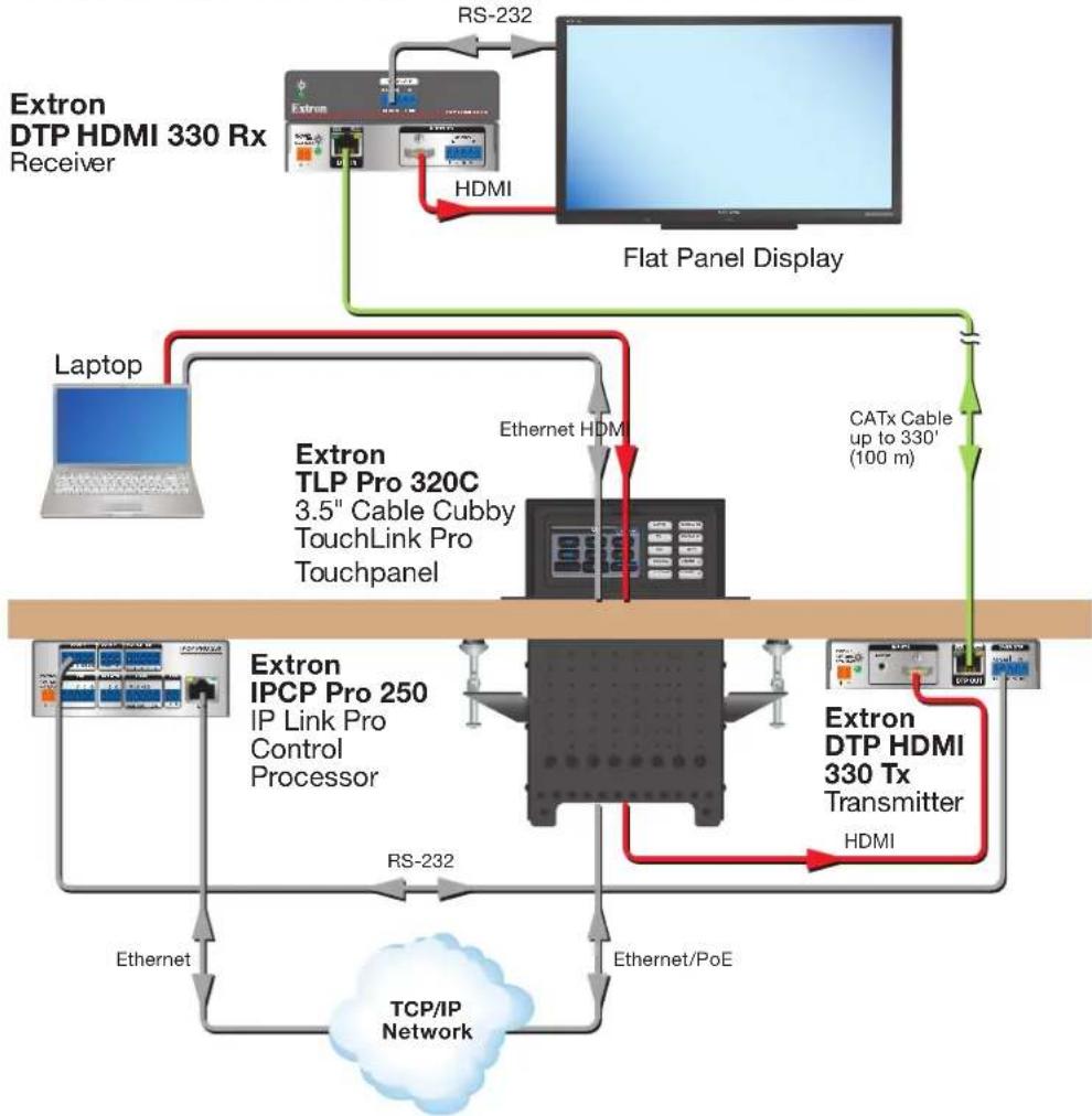
flowchart
graph TD
    A["Extron DTP HDMI 330 Rx Receiver"] -->|RS-232| B["Extron"]
    A -->|HDMI| C["Flat Panel Display"]
    C --> D["Laptop"]
    D --> E["Extron TLP Pro 320C 3.5" Cable Cubby TouchLink Pro Touchpanel"]
    E --> F["Extron IPCP Pro 250 IP Link Pro Control Processor"]
    F --> G["Extron DTP HDMI 330 Tx Transmitter"]
    G --> H["HDMI"]
    H --> I["TCP/IP Network"]
    I --> J["Ethernet"]
    J --> K["Extron"]
    style A fill:#f9f,stroke:#333
    style B fill:#ccf,stroke:#333
    style C fill:#cfc,stroke:#333
    style D fill:#fcc,stroke:#333
    style E fill:#cff,stroke:#333
    style F fill:#ffc,stroke:#333
    style G fill:#fcc,stroke:#333
    style H fill:#ffc,stroke:#333
    style I fill:#ccc,stroke:#333
Figure 1. Application Diagram
Requirements
Software
For a complete list of the requirements for running GUI Designer, Global Configurator Plus and Professional, or Toolbelt, see the Extron Web page for the appropriate software.
NOTE: The TLP Pro 320C is not compatible with Global Configurator 3 or GUI Configurator.
Hardware
An Extron IP Link Pro control interface must also be connected to the same network domain as the TouchLink panel. See www.extron.com for a list of suitable controllers.
NOTE: These touchpanels are not compatible with Extron IP Link (non-Pro) controllers.
Installation Overview
- Before starting, download and install the latest versions of the following software:
☐ GUI Designer — for designing layouts for Extron TouchLink Pro touchpanels and third party touch interfaces.
☐ Global Configurator Plus and Professional — for setting up and configuring the control processor and touchpanel.
□ Toolbelt — provides device discovery, device information, firmware updates, and configuration of network settings, system utilities, and user management for TouchLink Pro devices.
See Configuration Software on page 30.
- Obtain the following network information from your network administrator:
☐ DHCP status (on or off). If DHCP is off, you will also require
IP address
□ Subnet mask
Gateway
□ User name — by default, these are either admin or user.
☐ Passwords — by default, these are either extron (for admin) or the field is left blank (for user).
☐ MAC address — make a note of the touchpanel MAC address.
- Prepare to mount the Cable Cubby:
☐ Make sure you are familiar with all the included parts (see page 7) and have all the necessary tools (see page 7) for installing the cable cubby.
☐ Plan where you are going to install the Cable Cubby and how you are going to cut the hole.
☐ Ensure the TLP Pro 320C is oriented correctly and that there is adequate room for cables and cable retractors (optional).
☐ Ensure you are using the correct cut-out template or dimensions (see Cut-out Dimensions on page 8).
☐ Ensure the installation complies with all necessary regulations.
- Mount the Cable Cubby:
☐ Cut the table surface (see Cutting the Table on page 8).
☐ Run all cables to the unit (see Running Cables on page 10).
☐ Install cable retractors (optional) (see Installing Cable Retractors on page 10).
☐ Install the power module (optional) (see Installing Power Modules on page 11).
☐ Put together and install the AAP assembly (see Preparing and Installing the AAP Assemblies on page 12).
☐ Mount the Cable Cubby (see Mounting the TLP Pro 320C Enclosure on page 14).
- Connect cables to the touchpanel. The unit can be powered using a 12 VDC power supply or a Power over Ethernet (PoE) power injector.
☐ If required, connect the power supply (see Power Connector on page 17).
☐ Connect the network cable (see Network and Power over Ethernet Connector on page 19).
ATTENTION:
☐ Connect the PC that you will use for setup, the control processor, and the touchpanel to the same Ethernet subnetwork.
☐ Use the Setup Menu (see page 21) or the Toolbelt feature of Global Configurator Plus and Professional to set the DHCP status and, if necessary, the IP address, subnet mask, gateway, and related settings for the touchpanel.
- Configure the TLP Pro 320C — the GUI Designer Help File, the Global Configurator Help File, and the Toolbelt Help File, provide step-by-step instructions and detailed information. The Global Configurator Help File also includes an introduction to that software and sections on how to start a project and configuration.
Mounting
This section describes how to mount the TLP Pro 320C Cable Cubby. It covers:
- Planning
- Tools Required for Installation
- Included Parts
- Ensure Adequate Under-table Clearance for Retractors
• Cutting the Table - Running Cables
• Installing Cable Retractors (Optional)
• Installing Power Modules (Optional)
• Preparing and Installing the AAP Assemblies
• Mounting the TLP Pro 320C Enclosure
Planning
- Before making any cuts, select the best location for the TLP Pro 320C.
☐ Ensure that the edge that opens on the lid is oriented correctly.
☐ Ensure there is enough space for all the system cables and components, above and below the table. Take account of:
- Clearances for under-table cabling, especially if the cable has a large bend radius.
- Adequate space below the table for cable retractors if they are to be installed (see page 8).
• The number and type of AAPs required for the installation.
- The location of devices that connect to the AAPs either above or below the table.
-
Verify that you have the correct template or dimensions (see page 8).
-
Decide on the method for cutting a hole in the table (see Cutting the Surface on page 8). There are three methods available:
-
Hand router and template — requires a router template, which must be purchased separately.
• CNC wood router — must be programmed with the correct dimensions.
• Jigsaw — requires a paper template (available at www.extron.com).
The hand router used with the routing template or the CNC wood router are the most accurate methods for cutting the hole. Either one of these methods is recommended by Extron. The jigsaw is less accurate, but is also acceptable.
- Check all relevant regulations.
☐ Ensure that the installation complies with local, state, and national building and electrical codes.
☐ Ensure that the installation complies with the Americans with Disabilities Act or other accessibility requirements.
Tools Required for Installation
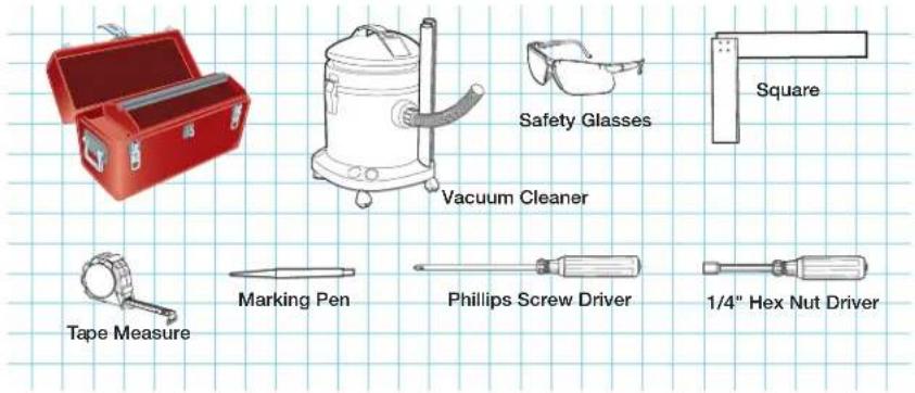
Figure 2. Tools Required to Install the TLP Pro 320C
Included Parts
Open the shipping container and verify that all the following components are present:
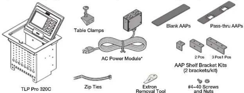
* The unit may be provided without a power module or with a different power module (see the table below).
| US Power Module | Universal Power Module | Without Power Module | |
| AC Power Module1 | 1 1 0 | ||
| Pass-through AAPs2,3 | 4 3 4 | ||
| Blank AAPs 3 3 5 | |||
| 1-position Bracket Kit4 | 0 1 0 | ||
| 2-position Bracket Kit 2 1 3 | |||
| 3-position Bracket Kit 1 1 1 |
NOTES:
1 Inside the US, the TLP Pro 320C can be purchased with or without an AC power module. Outside the US, see www.extron.com to find a power module that is suitable for your location.
2 Each AAP Bracket Kit consists of two brackets. The rear bracket is higher than the front bracket and has two holes for screws.
3 Active or Passive AAPs are not provided and must be purchased separately (see www.extron.com).
4 Single-space brackets can only be installed in one location (see the note and figure on page 12).
Figure 3. Parts Included with the TLP Pro 320C
Ensure Adequate Under-table Clearance for Retractors
Retractors are optional accessories for handling cables with the TLP Pro 320C. If you are using retractors, ensure that there is sufficient room beneath the table to accommodate them. Horizontal mounting provides maximum legroom and protects the retractors from accidental damage. Vertical mounting is used if space or access makes horizontal mounting difficult. To satisfy ADA compliance requirements, there is also an option to mount the retractors at a 30° angle (see the Retractors User Guide, which is available at www.extron.com).
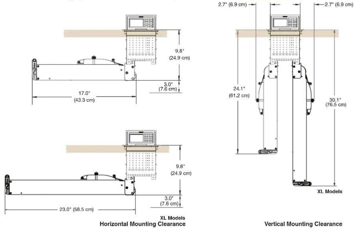
Figure 4. Under-table Clearance Requirements for Retractors
Cutting the Table
Cut-out Dimensions
There are three alternative methods of making the hole for the TLP Pro 320C (see Cutting the Surface below and on the following page):
- If using a hand router, you should purchase the TLP Pro 320C routing template (part number 70-694-01).
- If using a CNC wood router, use the exact cut-out dimensions.
- If using a reciprocating saw or jigsaw use the paper cut-out template.
Cutting the Surface
WARNING: Wear safety glasses when operating power equipment. Failure to comply can result in eye injury.
Be certain the cut is laid out in exactly the desired location and the edge that opens on the lid is correctly oriented. After verifying and checking dimensions, cut a hole in the surface of the furniture where the enclosure will be installed.
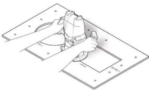
Router with routing template
If using a routing template, make sure it is the correct template for the TLP Pro 320C (part number 70-694-01). For complete instructions, see the Routing Template User Guide, available at www.extron.com.
NOTE: The metal router guide must be purchased separately. It is reusable and should not be discarded when the installation is complete.
natural_image
Technical line drawing of a hand using a tool to clean or adjust a mechanical component on a workbench (no text or symbols present)CNC router
If using a CNC router, enter the correct dimensions for the TLP Pro 320C: 7.50 +0.00/-0.02 inches W x 6.00 +0.00/-0.02 inches D 19.05 +0.00/-0.05 cm W x 15.24 +0.00/-0.05 cm D
NOTE: The width dimension (underlined) refers to the side with AAP access.
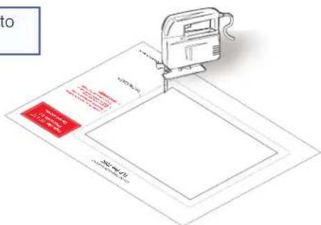
Reciprocating saw or jigsaw
If using a reciprocating saw or jigsaw, make sure to use the paper cutout template for the TLP Pro 320C. The template is available at www.extron.com.
Running Cables
Run all cables necessary to support the AC connector, the cables stored in the cubby, and all planned AAP connectors. Run the cables below the table and through the hole that was cut in the previous step (Cutting the Surface). Leave enough slack in the cables to connect or route them before the cubby is installed in the table. Leave enough slack for the external power supply and to connect AV cables and the cable for PoE and LAN to the TLP Pro 320C.
Installing Cable Retractors (Optional)
Extron cable retractors retract and store extended cables in Cable Cubby systems, preventing them from tangling underneath the table. Retractor kits are available for several cable types. Up to six retractors can be installed in the TLP Pro 320C enclosure (three at either end). They are not provided with the TLP Pro 320C and must be purchased separately.
The buttons on the retractors must be placed at one end of the unit and must, therefore, be the first or the last items added.
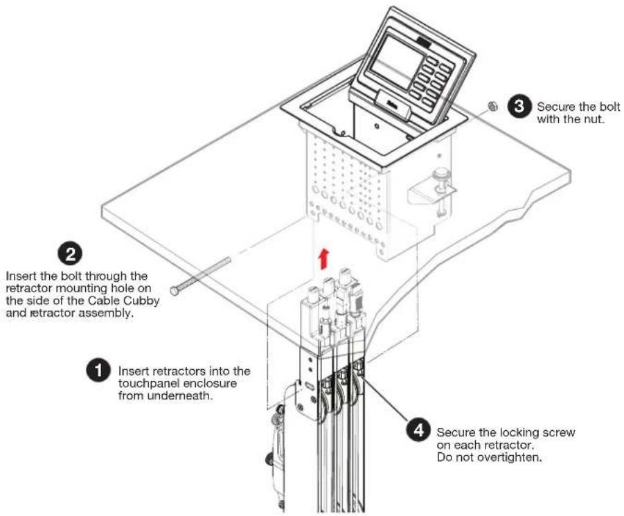
Figure 5. Installing Cable Retractors
To mount the retractors horizontally and for further information and installation instructions, see the Retractors User Guide, which is available at www.extron.com. The guide also provides information about mounting the retractors at a 30° angle to satisfy ADA compliance requirements.
Installing Power Modules (Optional)
WARNING:
AVERTISSEMENT :
NOTE: Different countries require different power adapters. See www.extron.com to select a power module that is suitable for your location.
The power module takes up two or three AAP spaces and may be installed before or after the AAP assembly is installed or, if desired, with AAPs on either side.
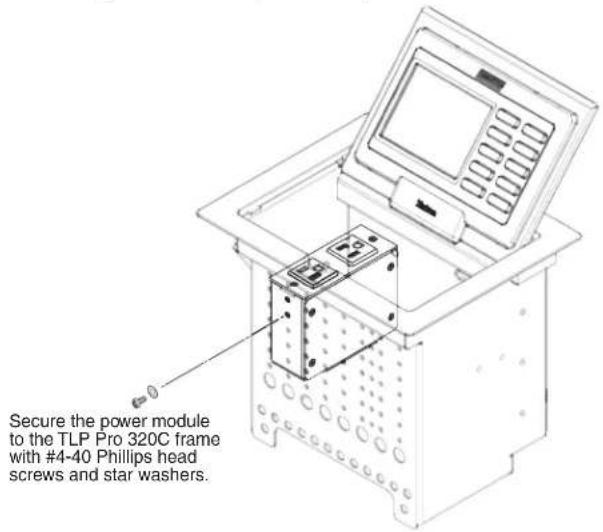
Figure 6. Installing a Power Module in the TLP Pro 320C
- Secure the power module with a minimum of two #4-40 Phillips head screws and star washers.
CAUTION: Risk of electric shock: To ensure proper electrical grounding, use the provided grounding screws and star washers.
- Run the cable or conduit to a convenient junction box. Extron recommends the circuit be attached to a junction box that is directly wired to the main circuit.
Preparing and Installing the AAP Assemblies
The AAP assembly organizes the AAPs onto a frame that can easily be inserted or removed from the TLP Pro 320C enclosure. Pass-through and blank AAP plates are provided with the TLP Pro 320C. Active or passive AAPs must be purchased separately. For the complete range of available AAPs, see www.extron.com.
If neither power modules nor cable retractors are installed, up to 9 AAPs can be accommodated. Cable retractors, if installed, occupy the space of two AAP slots. The power modules occupy the space of two (US) or three (European or Universal) AAP slots.
AAP brackets are available in one-space, two-space, and three-space configurations. Decide the location of each AAP prior to assembly. Pass-through AAPs provide direct cable connection and the cable must be installed as they are being mounted on the brackets.
TIP: The recommended way to install the cables and AAPs is to populate the brackets with AAP plates outside the enclosure as shown in Installing AAPs below, then install the populated AAP assemblies into the enclosure, as shown in Inserting the AAP Assemblies on the following page.
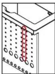
NOTE: An extra column of AAP bracket mounting points is available for use with TLP single-space AAP mounting brackets (see the illustration to the right). Single-space brackets will not fit in any other location.
natural_image
Technical diagram showing a mechanical or structural component with dotted lines and a red arrow indicating a specific section (no text or symbols present)The extra column of mounting points is for installing single-space AAP brackets.
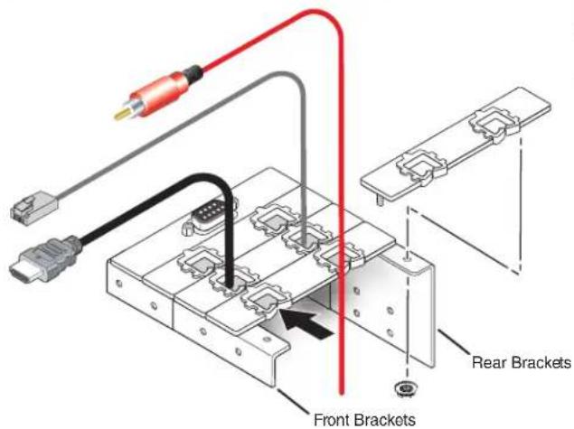
Figure 7. Preparing the AAP Assembly
Installing AAPs
-
Determine how many AAPs will be used and how many front and rear brackets will be needed. The brackets come in one-space, two-space, and three-space configurations. The rear brackets are taller than the front brackets.
-
Place the AAP onto the bracket. Ensure one end of the AAP is secured to a front bracket and the other end is secured to a rear bracket. Whenever possible match the width of the front and rear brackets.
NOTES:
• Active, passive and pass-through AAPs can be mixed.
- Cables can be attached to the active or passive AAPs after assembly.
- Insert cables into each pass-through AAP before the next AAP is added.
- Attach the AAP loosely to the bracket with the supplied #4-40 captive washer nuts.
NOTE: At this time, captive washer nuts should be hand tightened; otherwise it is difficult to attach the brackets to the frame of the TLP Pro 320C (see Inserting the AAP Assemblies below).
When using pass-through AAPs, ensure that the opening in the grommet is accessible for inserting cables, if required.
-
Insert one cable through the opening of each grommet. Cables can only be inserted into the pass-through AAP while the front edge is exposed. Securing the next AAP in place closes the opening on the previous AAP and ensures that the cable cannot escape.
-
Add AAPs until the bracket is filled. Spaces that are not required can be filled with blank AAPs.
Inserting the AAP Assemblies
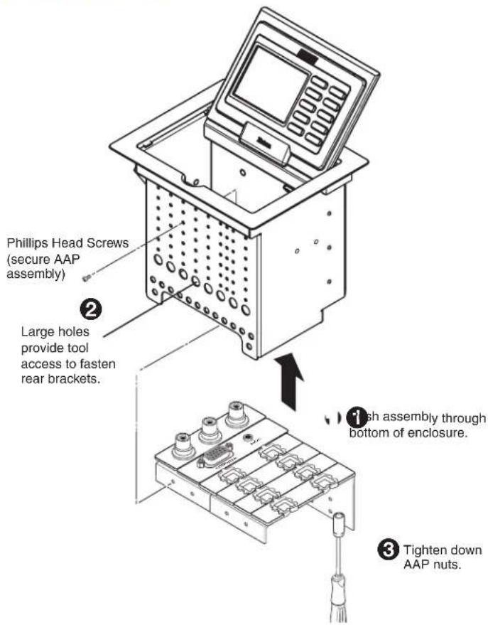
Figure 8. Inserting the AAP Assemblies
- Push the first AAP assembly through the bottom of the enclosure (①).
Align the holes in the rear bracket the bottom row of holes on the rear face of the enclosure and, if necessary, pull any pass-through cables out of the way. - Insert a long screwdriver through the large slot in the front panel to secure the rear bracket to the rear face of the enclosure with the provided #4-40 Phillips head screws (②).
- Secure the front bracket to the front face of the enclosure, using the provided #4-40 Phillips head screws.
- Use a hex nut wrench to tighten the AAP captive washer nuts (③).
- Repeat steps 1 through 4 to add each AAP assembly.
- Run cables to connect the source and output devices to the active and passive AAPs.
Mounting the TLP Pro 320C Enclosure
Mount the cable cubby enclosure in the table.
CAUTION: The flanged edges of the top of the surface enclosure are sharp. These edges are also soft and may be easily nicked or bent. Exercise caution when handling the enclosure to prevent personal injury or damage to the enclosure.
Figure 9. Mounting the TLP Pro 320C Enclosure
- Remove the edge grommet protecting the edges of the trim ring (⑤) and the plastic film on the finished surfaces.
ATTENTION:
- Do not use isopropyl alcohol or other solvents to clean the Cable Cubby. Strong solvents will ruin some finishes.
-
Ne pas utiliser de l'alcool isopropylique ou d'autres solvants pour nettoyer le Cable Cubby. Les solvants forts endommageront certaines finitions.
-
Carefully lower the enclosure into the hole cut in the table (see Cutting the Surface on page 8). Ensure the trim ring (5) is flush with the top of the table.
- Under the table, attach the table clamps (③) to the pins on each side of the enclosure. It may be necessary to loosen the wingnuts (①) and the Phillips head screws (②).
- Tighten the Phillips head screws until the clamp faces (④) are tightly secured against the bottom of the table.
- To prevent the screws from becoming loose, secure the wingnuts against the table clamp bodies.
Panel Features
This section discusses:
- Front Panel Features
- Connectors
Front Panel Features
With the lid open, remove the front panel bezel, as shown in figure 10, using the Extron removal tool.
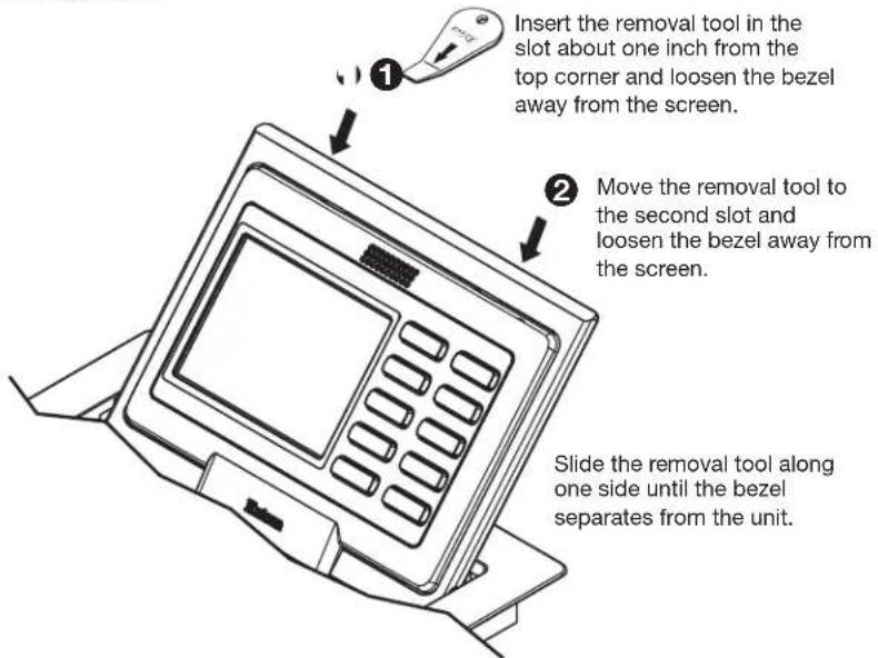
Figure 10. Removing the Bezel
ATTENTION:
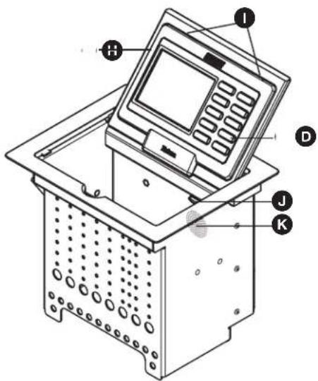
Figure 11. TLP Pro 320C Front Panel with Bezel Removed
With the lid down, the ambient light sensor (figure 11, B), the LCD screen (C), and illumination LED (J, below right) are disabled. All three are activated by opening the lid.
A Communication LED — shows the touchpanel configuration and connection status:
- Unlit during normal operation (the touchpanel is configured and connected to an IP Link Pro control processor).
- Blinks red if the touchpanel has been configured but is not connected to an IP Link Pro control processor.
• Permanently lit if the touchpanel has not been configured.
The LED can be toggled between enabled and disabled (see setup menu on page 21).
B Ambient light sensor — monitors ambient light level and adjusts screen brightness, based on the settings configured using the setup menu Display screen (see page 26).
© LCD screen — the TLP Pro 320C has a 3.5 inch screen with a 320x240 resolution.
D Configurable buttons — 10 dedicated, customizable, function buttons provide quick access to key functions.
E Reset LED— indicates power status and reset status of the device.
F Reset button — this button allows the unit to be reset. The TLP Pro 320C has three reset modes that are initiated by pressing the reset button (see Reset Modes on page 36).
Menu button — activates the setup menu (see page 21) and calibration screen (see page 29).
H Bezel — use the included removal tool to detach the bezel.
① Bezel removal slots — for removing bezel, using Extron removal tool (see figure 10 on page 15).
J Illumination LED — provides light for cable cubby enclosure.
K Speaker — one, placed inside the cable cubby, provides audible feedback for the user.
Connectors
The cable connections are located in a panel on the bottom of the TLP Pro 320C:
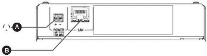

Power Connector

LAN/PoE
Figure 12. Cable Connectors for TLP Pro 320C
The TLP Pro 320C can use a 12 VDC desktop power supply and is also Power over Ethernet (PoE 802.3af, class 3) compliant.
NOTE: The TLP Pro 320C ships without a power supply. Either the 12 VDC power supply or the PoE injector must be purchased separately.
Extron recommends that you use the following power sources:
• 12 VDC — PS 1210C power supply (part number 70-775-01).
• Power over Ethernet — XTP PI 100 power injector (part number 60-1233-01).
ATTENTION:
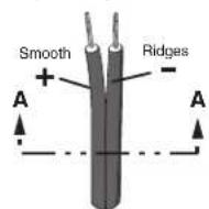
Connect a 12 VDC, 1.0 A power supply (not provided) to this 2-pole, 3.5 mm captive screw connector. Ensure the connections have the correct polarity as shown below.
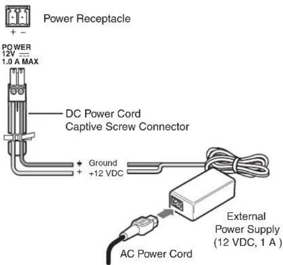
Power Supply
Output Cord

SECTION A-A

POWER
12V ---
1.0 A MAX
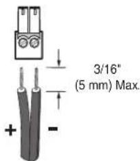
Figure 13. Power Supply Connection
ATTENTION:
Network and Power over Ethernet Connector
Connect the TLP Pro 320C to the LAN using a twisted pair cable, terminated with an RJ-45 connector. Use a straight-through Ethernet cable to connect the panel to a switch or router. Use a crossover cable to connect the panel directly to a computer.
An Extron IPL Pro Control Processor must also be connected to the same network domain as the TouchLink Touchpanel. See www.extron.com for a list of suggested models.
The network port has two LEDs. The green LED lights steadily to indicate that the touchpanel is connected correctly to a network. The yellow LED blinks to indicate that data is being passed to or from the touchpanel.
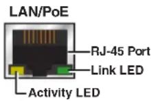
The TLP Pro 320C can use a 12 VDC desktop power supply and is also Power over Ethernet (PoE 802.3af, class 3) compliant. Extron recommends using a PoE power injector and, when a power injector is used, Extron recommends the XTP PI 100 power injector (part number 60-1233-01), which is shown in figure 14 below.
NOTE: The TLP Pro 320C ships without a power supply. Either the 12 VDC power supply or the PoE injector must be purchased separately.
To use a PoE power injector, connect a straight-through Ethernet cable to the power supply and a switch or router. This cable carries network information from the switch or router to the power supply input. A second straight-through cable carries the network information and 48 VDC from the power supply to the TLP Pro 320C. Connect the IEC power cord to a convenient 100 VAC to 240 VAC, 50-60 Hz power source.
If a 12 VDC power supply is being used (see page 17) run one straight-through cable from the LAN/PoE connector directly to a switch or router.
ATTENTION:
The figure below shows the Extron XTP PI 100. Your power injector may look different.
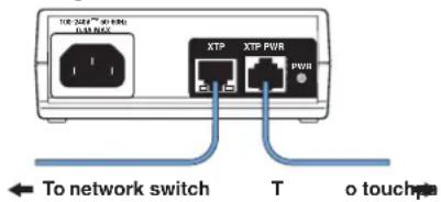
Figure 14. Connecting the Power Injector
ATTENTION:
When the TLP Pro 320C is powered on, the currently loaded project is displayed. To access the setup menu, remove the front panel bezel and press the Menu button (see figure 11, G on page 16). There are five available screens:
- Status
- Network
- Display
- Audio
- Advanced
There is also a Calibration screen.
To navigate between different screens, press the Menu icon in the top left corner.
The screen selection menu opens over the current screen, which is grayed out. The menu has five buttons, corresponding to the five available screens:

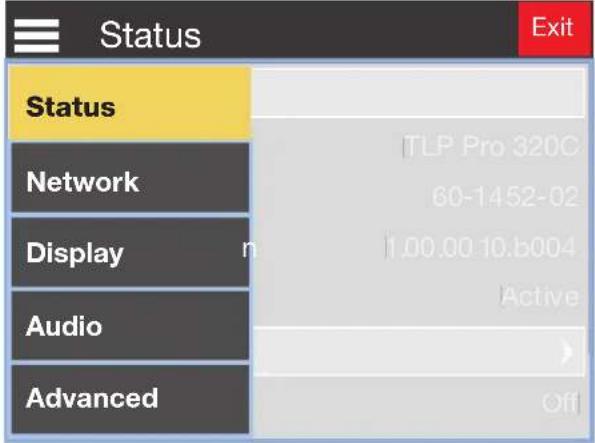
Figure 15. Screen Selection Menu
The button for the screen that is currently selected is yellow with black text. The other screens are gray with white text.
Press the name of the screen you wish to open.
There is also a red Exit button in the top right corner of the screen. Press this button to apply and save any changes and to close the menu screens.
Status Screen
This screen opens by default. To access the Status screen from any other part of the Setup menu, press the Menu icon in the top left corner and then press the Status button.
The image below shows the entire Status screen. Because of size of the touchscreen, you can only see part of the Status screen at any time. Flick the touchscreen with your finger to navigate up or down within the screen.
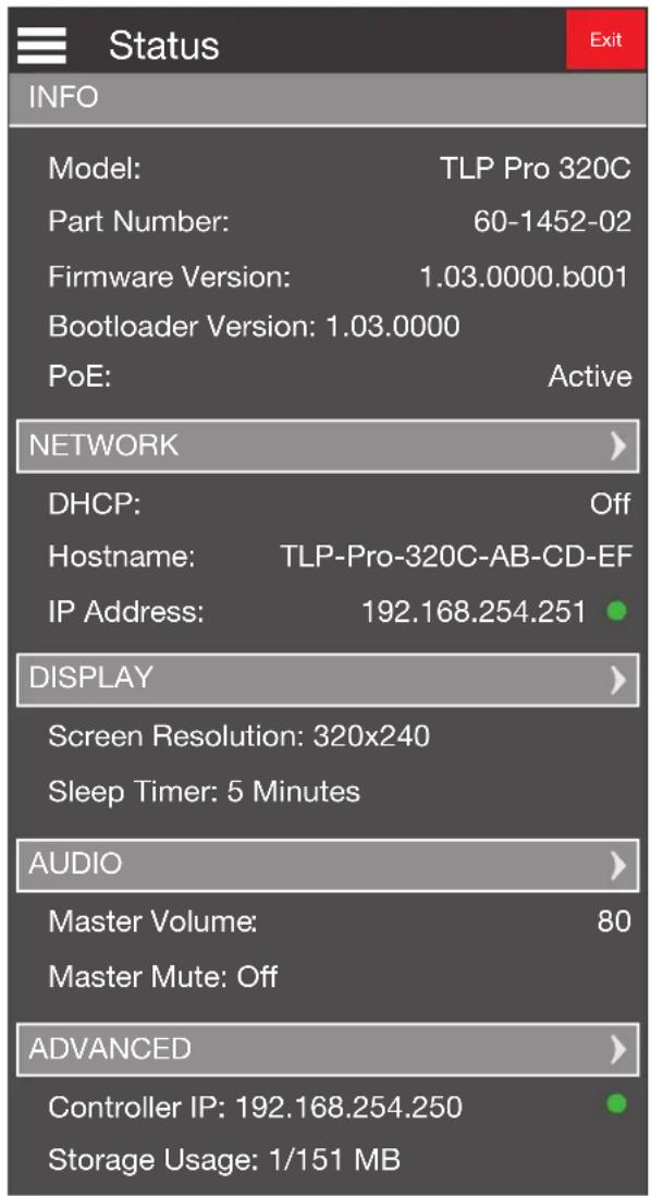
Figure 16. Status Screen
The Status screen is a read-only screen that provides basic information about the touchpanel. Each section of the screen shows a summary of the information on the other screens. More information about each topic can be found on the Network, Display, Audio, and Advanced screens. To navigate to the appropriate screen, click the light gray bar for that screen. Alternatively, you can use the Menu icon in the top left corner.
The indicator in the Network panel is green when there is a network connection or amber if there is no connection. The indicator in the Advanced panel is green when a control processor is connected or amber if none is connected.
Network Screen
The image below shows the entire Network screen. Because of size of the touchscreen, you can only see part of the screen at any time. Flick the touchscreen with your finger to navigate up or down within the screen.
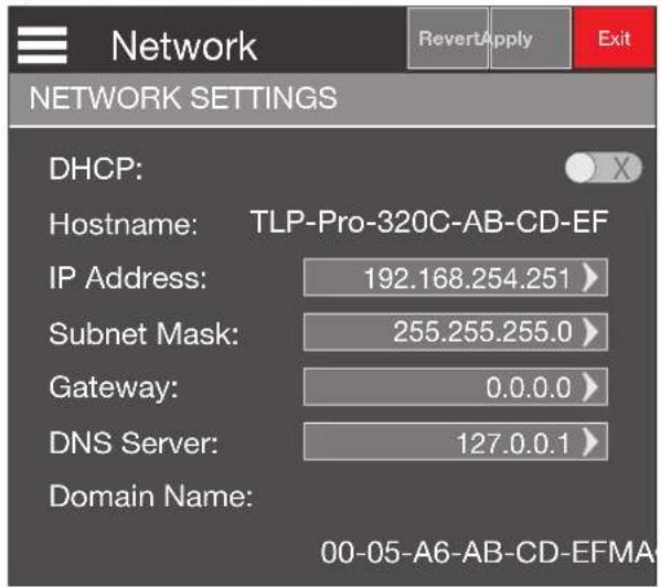
Figure 17. Network Screen
The Domain Name (optional) and MAC Address are read-only.
Verify with your network administrator whether the network settings for the touchpanel are assigned by Dynamic Host Configuration Protocol (DHCP) or set manually. If they are set manually, obtain an IP address, a subnet mask, a gateway address, and a Domain Name Server (DNS) IP address from the network administrator.
- If IP addresses are assigned manually, press the DHCP slider to the Off position.

Off
When the slider is off, the IP Address, Subnet Mask, Gateway, and DNS Server values can all be edited (they are shown on a gray button that can be pressed). There is an arrowhead beside each button.

On
If IP addresses are assigned by DHCP, Press the DHCP slider to the On position. When the slider is on, the IP Address, Subnet Mask, Gateway, and DNS
Server values cannot be edited (they are shown in white text, with no button and no arrowhead). Only the Host Name can be edited.
- Edit the IP address by pressing the appropriate text box on the Network screen. A numeric keypad opens with the current IP address displayed (1):
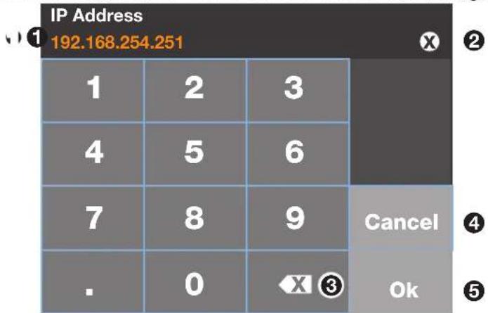
Figure 18. Numeric Keyboard
a. To delete the entire existing number, press the white circle with an X (2). To delete individual digits, use the backspace key ③).
b. Enter the IP address by pressing the numbered keys. You must also enter the period between each octet.
The value for any individual octet must be between 0 and 255. You cannot enter an invalid number. For example, if you attempt to enter 401, you will be able to enter the 4 and the 0, but you will not be able to enter the 1.
c. Press 0k (5) to save your changes and close the keypad.
Press Cancel (4) to close the keypad without saving any changes.
d. When you save changes, you return to the Network screen. The Apply and Revert buttons turn red.
Press Apply to keep the changes that you have made.
Press Revert to go back to the previous IP address.
-
Repeat step 2 to update the Subnet Mask, Gateway, or DNS Server values, as required.
-
If you set DHCP to On in step 1, you cannot edit the IP Address, Subnet Mask, Gateway, or DNS Server values. However, you can edit the Hostname.
The default Hostname is formed from the product name and the last three pairs of digits in the MAC address.
To edit the Hostname, press the Hostname button. an alphanumeric keyboard opens with the current Hostname displayed (1):
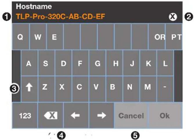
Figure 19. Alphanumeric Keypad
a. To delete the entire existing Hostname, press the white circle with an X (2).
b. You can delete individual characters by pressing the backspace key (4). Use the navigation arrows (5) to move the cursor as required.
c. Enter the new Hostname, using the keys. By default the letters are upper case. You can toggle between upper and lower case by using the up-arrow key (③). You can open a numeric keypad to add numbers by pressing the 123 key.
You can use any letter (upper case or lower case), any number (0-9), and hyphens. There is no limit on the length of the name.
d. When you have finished entering the name, press 0k to save the new name or Cancel to exit the keyboard without saving the changes.
e. When you save changes, you return to the Network screen. The Apply and Revert buttons turn red.
Press Apply to keep the changes that you have made.
Press Revert to go back to the previous Hostname.
Display Screen
The image below shows the entire Display screen. Because of size of the touchscreen, you can only see part of the screen at any time. Flick the touchscreen with your finger to navigate up or down within the screen.
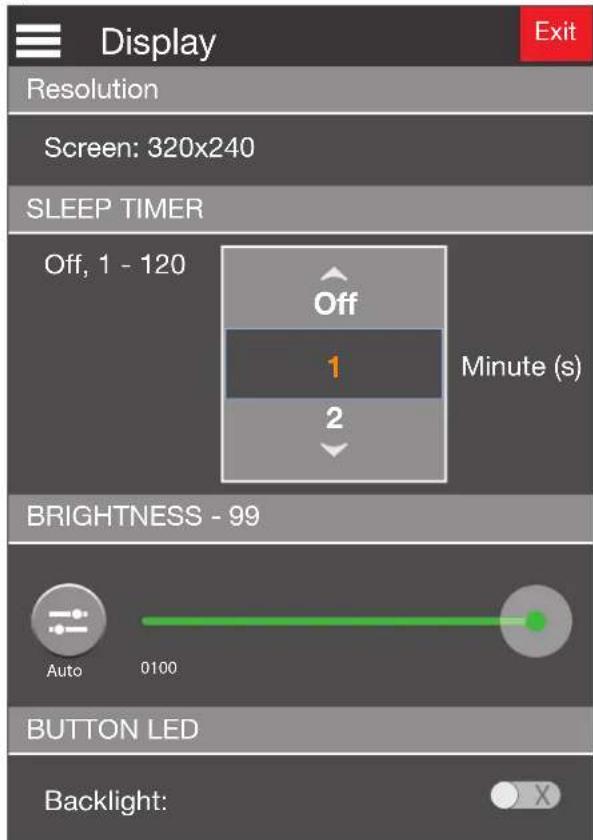
Figure 20. Display Screen
The Display screen allows you to set the Sleep Timer, Brightness, and Button LED.
• Resolution (320x240) is read-only.
- Sleep Timer — determines how long the panel will be inactive before it enters sleep mode. In sleep mode, the screen goes dark to save power. Use the up and down arrows to switch the sleep timer Off or to set a value between 1 and 120 minutes.
- Brightness — provides a suitable amount of backlighting that is automatically calculated from the amount of ambient light detected by the light detector. Press the gray circle and drag it along the green line to adjust the brightness setting between 0 and 100.
- Button LED — provides LED backlighting for the eight front panel buttons next to the touchscreen. Toggle between On and Off.
Audio Screen
The image below shows the entire Audio screen. Because of size of the touchscreen, you can only see part of the screen at any time. Flick the touchscreen with your finger to navigate up or down within the screen.
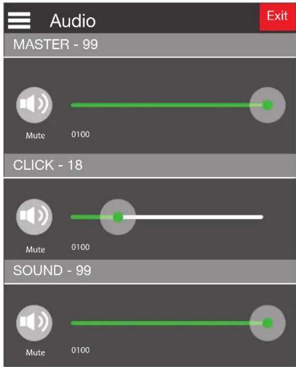
Figure 21. Audio Screen
On the Audio screen, use the slider controls to adjust the Master, Click, and Sound volume settings.
Master sets the maximum volume for all the other sound volume settings. For example, if the Master volume is set to 80 (80 percent of maximum), even when the Sound volume is set to 100, it is equivalent to only 80 percent of maximum.
Click sets the volume for audible feedback that accompanies events such as a screen button being pressed.
Sound sets the volume of audio from any audio file playback. To mute any of the volume settings, press the corresponding loudspeaker icon to toggle between mute off and mute on.

Mute Off

Mute On
Advanced Screen
The image below shows the entire Advanced screen. Because of size of the touchscreen, you can only see part of the screen at any time. Flick the touchscreen with your finger to navigate up or down within the screen.
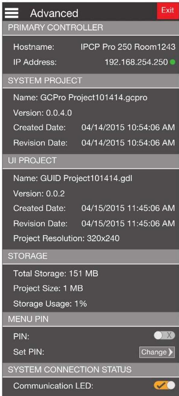
Figure 22. Advanced Screen
The first four panels (Primary Controller, System Project, UI Project, and Storage) are read only.
Menu PIN section — allows you to enable or disable PIN use. If PIN use is enabled, it allows you to set the pin.
By default, PIN use is disabled.
- Press the PIN slider to enable PIN use. The Enter New PIN numeric keypad opens:
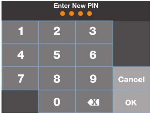
Figure 23. Numeric Keypad for Setting PIN
- Set the PIN. The PIN is a 4-digit number. Each digit can have any value from 0-9. As the digits are entered, four dots appear below the title.
- The dots can be deleted by pressing the backspace character.
- Press Cancel to close the keypad without entering a PIN.
- When four digits have been entered, the 0k button is enabled.
- Press OK to save the PIN.
- The title bar changes to Confirm New Pin.
- Enter the PIN a second time. When the PIN entered on the second occasion matches the PIN entered on the first occasion, the PIN is set and the dialog closes.
If the second version of the PIN does not match the original, the message Pin entry does not match. Try again. appears at the top of the screen for a few seconds before you are returned to the Enter New PIN screen (step 1).
System Communication Status — determines whether the Communication LED (see figure 11, E on page 16) is enabled or disabled.
Calibration Screen
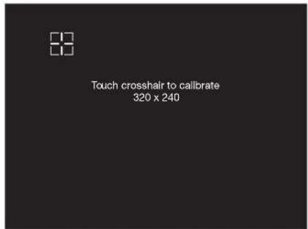
Figure 24. Calibration Screen
- Press the Menu button for at least 3 seconds (see figure 11 G, on page 16).
- Release the button.
The calibration screen opens to show cross-hairs. - Follow the on-screen instructions until all five sets of cross hairs have been calibrated (one in each corner and a fifth in the center of the screen).
- The touchpanel exits the calibration screen once the calibration process is completed.
- If required, re-attach the bezel.
TLP Pro 320C • Setup Menu 29
Configuration Software
This section of the user guide provides information about:
- Configuration Software
• TLP Pro 320C Web Page - Updating the Firmware
Configuration Software
Use Toolbelt to provide device information, firmware updates, and configuration of network settings, system utilities (reset, reboot), and user management (username and password) for TouchLink Pro devices.
Use GUI Designer and Global Configurator Plus and Professional to design a graphical user interface (GUI) for the TouchLink Pro touchpanel:
- Design the layout of the screen text and graphics using GUI Designer, which is a Windows-based application. You can either customize an existing template or create an entirely new interface. GUI Designer offers several templates.
- After the user interface has been designed, the project is saved, built, and imported into Global Configurator Plus and Professional.
- Use Global Configurator Plus and Professional to assign functions to the text, graphics, front panel buttons, and front panel volume controller.
- After assigning the control functions, the project is rebuilt and uploaded to the control processor and touchpanel.
The GUI Designer and the Global Configurator Plus and Professional programs provide versatility and adaptability for configuration and control of an AV system as it grows and evolves.
Installing GUI Designer, Global Configurator, and Toolbelt
NOTE: Use GUI Designer and Global Configurator Plus and Professional to configure the TLP Pro 320C.
GUI Designer, Global Configurator Plus and Professional, and Toolbelt can be downloaded from www.extron.com. Select the Download tab (①) and click the Software (②) option in the sidebar at the left.
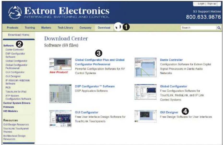
Figure 25. Software Downloads from the Extron Website
Select the link to Toolbelt, Global Configurator Plus and Professional ③) or GUI Designer (④). If they are not available on the Software home page, scroll down the page to the alphabetic menu bar and click on the appropriate initial letter.
Scroll down the list of options to the desired software.
Click the Download button next to the program and follow the on-screen instructions.
NOTES:
- You will need an Extron Insider account to run Global Configurator Plus and Professional. To obtain one, contact the Extron Sales Department.
- Ensure you are downloading Global Configurator Plus and Professional.
Using the Software
Use the appropriate software help file for step-by-step instructions and more detailed information. The Global Configurator Help File also includes an introduction to the software and sections on how to start and configure a project.
GUI Designer
Use the GUI Designer software to design the screen layout for the touchpanel. See the GUI Designer Help File for step-by-step instructions and more detailed information.
Global Configurator Plus and Professional
Use the Global Configurator software to set up and configure the control processor and the touchpanel. See the Global Configurator Help File for step-by-step instructions and more detailed information. The Global Configurator Help File also includes an introduction to the software and sections on how to start and configure a project.
Toolbelt
Use the Toolbelt software for device discovery, device information, firmware updates, and configuration of network settings, system utilities, and user management for TouchLink Pro devices.
TLP Pro 320C Web Page
To access the touchpanel default Web pages, enter the IP address of the unit into the Web browser of a PC connected to the same subnet. There is a single, read-only page that provides general and network information about the unit (see figure 26, below). It also allows you to upgrade the unit firmware.
A dialog opens asking for your user name and password. By default, the user name is admin and the password is extron (both user name and password are all lower case).
The single page provides general and network information about the unit. It also allows you to upgrade the unit firmware. This page cannot be used to configure the touchpanel network settings. To configure those settings, use the Setup Menu (see page 21) or the Toolbelt feature of Global Configurator.
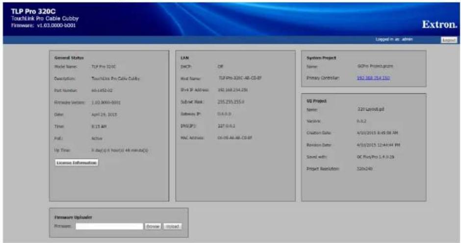
Figure 26. TLP Pro 320C Web Page
Click the License Information button to view details about third-party packages and associated licensing (and see Licensed Third-Party Software Used in the Touchpanels on page 39).
Updating Firmware
Firmware for the TLP Pro 320C can be upgraded in one of two ways:
- Updating Firmware Using the Touchpanel Web Page (see below)
- Updating Firmware Using Toolbelt (see below)
Before starting, consult your IT team and ensure that the touchpanel has a unique IP address.
Downloading Firmware
- Power on a computer that is connected to the same network as the touchpanel.
- On the Extron Website, click Download in the menu bar along the top of the page (1).
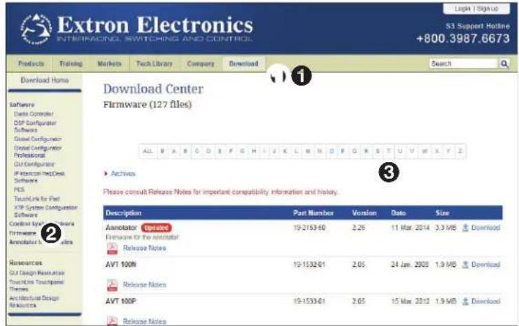
Figure 27. Firmware Download Center
- Click Firmware in the menu bar in the left side bar ②).
- Click the letter T from the list of letters ③).
- Scroll down the page until you find the firmware for the TLP Pro 320C.
- (Optional) Click Release Notes for more information about the program.
- Click Download.
- Follow the on-screen instructions to download the program. Make a note of where the firmware file is stored on the PC.
Updating Firmware Using the Touchpanel Web Page
- If you have not already done so, download the firmware file to a computer on the same network as the touchpanel (see the previous section).
- Open the touchpanel Web page (see TLP Pro 320C Web Page on the previous page).
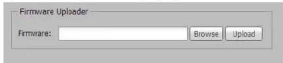
Figure 28. Touchpanel Web Page: Firmware Uploader
- Click Browse and navigate to the firmware location.
- Click Upload. The firmware file is uploaded to the touchpanel. Follow the on-screen instructions.
Updating Firmware Using Toolbelt
For complete information about using Extron Toolbelt to update firmware, see the Toolbelt Help File.
Reference Material
This section describes:
• Network Port Requirements
- Reset Modes
- Configurable Buttons
- Licensed Third-Party Software Used in the Touchpanels
Network Port Requirements
Network administrators may find it useful to know which ports, protocols, and services are used by the IP Link Pro control processors, TouchLink Pro Touchpanels, Global Configurator Plus and Professional software with Toolbelt, and TouchLink for iPad (for IP Link Pro control sytems). The following tables provide that information as a reference for network planning and troubleshooting. The following definitions apply:
- Inbound — The Extron control hardware listens for inbound traffic on the specified port.
- Outbound — The Extron control hardware sends outbound traffic to the specified port.
IP Link Pro Control Processors
| Ports and Protocols for Control Processors | ||||
| Inbound/Outbound | Port Protocol Service Description | |||
| Inbound 80 | TCP HTTP Port redirects to HTTPS | |||
| Inbound/Outbound | 123 UDP NTP NTP service | |||
| Inbound 443 | TCP HTTPS Default Web pages, GlobalViewer, TouchLink for Web | |||
| Inbound/Outbound | 4502 | UDP Discovery Broadcast network discovery | ||
| Inbound | 4503 | TCP SSH Internal system messaging | ||
| Outbound | 4504 | UDP Trace Extron trace messages | ||
| Inbound | 4522 | TCP SFTP File transfer | ||
| Outbound | 5555 (configurable) | UDP GVE GVE protocol | ||
| Outbound | Various | TCP/UDP Drivers | Outbound connections for Ethernet device control | |
TouchLink Pro Touchpanels
| Ports and Protocols for Control Processors | |||
| Inbound/Outbound | Port Protocol Service Description | ||
| Inbound 80 | TCP HTTP | Port redirects to HTTPS | |
| Outbound 123 | UDP NTP | NTP service | |
| Inbound 443 | TCP HTTPS | Default Web pages, | TouchLink for Web |
| Inbound/Outbound | 4502 | UDP Discovery Broadcast network discovery | |
| Inbound/Outbound | 4503 | TCP SSH Internal system messaging | |
| Inbound | 4522 | TCP SFTP File transfer | |
Global Configurator Plus and Professional Software
| Ports and Protocols for Control Processors | ||||
| Inbound/Outbound | Port Protocol Service Description | |||
| Outbound | 4503 | TCP SSH Internal system messaging | ||
| Inbound | 4504 | UDP Trace | Extron trace messages | |
| Outbound | 4522 | TCP SFTP File transfer | ||
Toolbelt Software
| Ports and Protocols for Control Processors | ||||
| Inbound/Outbound | Port Protocol Service Description | |||
| Inbound/Outbound | 4502 | UDP Discovery Broadcast network discovery | ||
| Outbound | 4503 | TCP SSH Internal system messaging | ||
| Inbound | 4504 | UDP Trace | Extron trace messages | |
| Outbound | 4522 | TCP SFTP File transfer | ||
TouchLink for iPad (for IP Link Pro Control Systems)
| Ports and Protocols for Control Processors | |||
| Inbound/Outbound | Port | Protocol Service | Description |
| Inbound/Outbound | 4503 | TCP SSH Internal system messaging | |
| Inbound 4522 | TCP SFTP | File transfer | |
| Inbound 433 | TCP HTTPS File transfer | ||
Reset Modes
The TLP Pro 320 C touchpanel has three reset modes:
• Use Factory Firmware (see below).
- Reset All IP Settings (see page 36).
- Reset to Factory Defaults (see page 36).
To initiate these modes, press the Reset button, which is found on the front panel after removing the bezel (see figure 11, F on page 15).
Use Factory Firmware
Purpose and notes
Use this mode to temporarily boot up the unit with factory installed firmware for a single power cycle in the event that a firmware update has failed or if incompatibility issues arise with user-loaded firmware.
NOTE: User-defined Web pages may not work correctly with an earlier firmware version.
Activation
To start the Use Factory Firmware reset mode and replace firmware:
- On the panel, hold down the recessed Reset button while applying power to the unit. When power is restored, the Reset LED lights. Hold the Reset button for a further 2 seconds before releasing it. The touchpanel enters factory firmware mode.
- Upload new firmware to the unit as desired (see Updating the Firmware on page 32).
NOTE: After a Use Factory Firmware reset is performed, update the TouchLink Pro firmware to the latest version. Do not operate the touchpanel firmware version that results from the reset. This mode temporarily resets the unit to factory default until power is recycled. If you want to use the factory default firmware, you must upload that version again (see Updating the Firmware on page 32).
Result
The unit continues to run factory-installed firmware until the user updates the firmware or power is cycled to the unit, which then reboots with the last loaded version of the firmware. The touchpanel reverts to the factory default firmware. Event scripting does not start if the unit is powered on in this mode. All user files and settings such as drivers, adjustments, and IP settings are maintained.
NOTE: To return the unit to the firmware version that was running prior to the reset, cycle power to the unit.
Reset All IP Settings
Purpose
Reset All IP Settings mode enables you to reset IP settings and port maps to factory defaults.
Activation
To reset all IP settings:
- Hold down the Reset button for about 6 seconds until the Reset LED blinks twice (once at 3 seconds, again at 6 seconds).
- Release and press Reset momentarily (for less than 1 second) within 1 second. Nothing happens if the momentary press does not occur within 1 second.
Result
Reset All IP Settings mode:
- Sets the IP address back to factory default (192.168.254.251)
- Sets the subnet back to factory default (255.255.255.0)
- Sets the default gateway address to the factory default (0.0.0.0)
- Sets all other IP settings, addresses, and domain and host names back to factory default.
- Turns DHCP off.
Reset to Factory Defaults
Purpose
This mode is useful if you want to start over with configuration and uploading.
Activation
To reset the unit to all factory default settings:
- Hold down the Reset button for about 9 seconds until the Reset LED blinks three times (once at 3 seconds, again at 6 seconds, again at 9 seconds).
- Release and press Reset momentarily (for less than 1 second) within 1 second. Nothing happens if the momentary press does not occur within 1 second.
Result
Reset to Factory Defaults mode performs a complete reset to factory defaults (except the firmware).
- Does everything Reset All IP Settings mode does.
- Removes touchpanel configurations and user interface.
Installing or Replacing Buttons
The TLP Pro 320C has ten dedicated, customizable function buttons to provide quick access to key functions. The buttons must be associated with their function by configuring them with Global Configurator Plus or Professional (see the Global Configurator Help File).
The unit ships with the following default set of buttons installed:
| Laptop Display On | |
| PC Display Off | |
| DVD Mute | |
| Doc Cam Volume | ▲ |
| Auxiliary Volume | ▼ |
Any or all of these buttons can be replaced if they are assigned different functions when the unit is customized. Replacement buttons come in pre-packaged kits or can be ordered individually. For a complete list of available options, see the TLP Pro 320C product page at www.extron.com. An order form can be downloaded from the same site.
Button Replacement
The instructions below show how to replace the button labels on the TLP Pro 320C:
- Disconnect power from the touchpanel.
- Remove the bezel using the Extron removal tool (see figure 10 on page 15).
- Tip the bezel forward as it is being removed so that the buttons do not fall out.
- Lay the bezel face down and remove the buttons that need to be replaced.
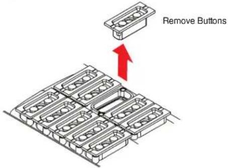
Figure 29. Button Replacement
- Insert the replacement buttons making sure that they are in the correct orientation.
- Replace the bezel that was removed in step 2. Four clips, two at the top and two at the bottom, snap into place, audibly.
- Reconnect the power to the touchpanel.
Licensed Third-Party Software Used in the Touchpanels
The touchpanels use various licensed third-party software packages during operation. To view details about third-party packages and associated licensing, click the License Information button on the TLP Pro 320C Web page (see on page 32).
To view a copy of a listed package license, in the License Information window, click the link in the License column for the relevant package. This opens in a separate window a copy of the package license.
The following table lists the licensed third-party software packages used by the touchpanels.
NOTE: Licensed third-party software packages used by the touchpanels are subject to change without notice.
| Licensed Third-party Software Used in the TLP Pro 320C | |||
| Package License | Package License | ||
| aufs2-util GPL v2 avahi | LGPL v2.1 | ||
| bstrlib BSD busybox GPL v2 | |||
| bzip2 BSD can-utils GPL v2 | |||
| cjson MIT devmem2 | GPL v2 | ||
| expat | MIT gi | fcgi | |
| gnupg-1.4.7 | GPL v2 gpgme-1.3.0 | LGPL v2.1 | |
| i2c-tools | GPL v2 ifplugd | GPL v2 | |
| json4lua | MIT Libassuan-2.0.1 | LGPL v2.1 | |
| Libcgicc-3.2.3 | LGPL v2.1 | libcurl | ICS |
| libdaemon | LGPL v2.1 | libdnet | BSD |
| libfcgi | fcgi | libffi | libaffi |
| libgpg LGPL v2.1 | libnl | LGPL v2.1 | |
| libpcap | BSD libsocketcan | LGPL v2.1 | |
| libssh2 | BSD libusb | LGPL v2.1 | |
| lighttpd BSD linux-kernel | GPL v2 | ||
| linux-pam | BSD lua | MIT | |
| luafilesystem | MIT luasocket MIT | ||
| minicom GPL v2 mtd | GPL v2 | ||
| ncurses | MIT netsnmp | BSD | |
| ntp | MIT openssh | BSD | |
| openssl | OpenSSL | pcre | BSD |
| pexpect | MIT popt MIT | ||
| psmisc | GPL v2 python3 | PSF | |
| qt | LGPL v2.1 | socat | GPL v2 |
| spawn-fcgi | BSD sqlite Public-domain | ||
| tcpdump BSD tzdata | Public-domain | ||
| uboot | GPL v2 udev | GPL v2 | |
| xinetd BSD zlib | zlib | ||
Extron Warranty
Extron Electronics warrants this product against defects in materials and workmanship for a period of three years from the date of purchase. In the event of malfunction during the warranty period attributable directly to faulty workmanship and/or materials, Extron Electronics will, at its option, repair or replace said products or components, to whatever extent it shall deem necessary to restore said product to proper operating condition, provided that it is returned within the warranty period, with proof of purchase and description of malfunction to:
USA, Canada, South America, and Central America:
Extron Electronics
1230 South Lewis Street
Anaheim, CA 92805
U.S.A.
Japan:
Extron Electronics, Japan
Kyodo Building, 16 Ichibancho
Chiyoda-ku, Tokyo 102-0082
Japan
Europe and Africa:
Extron Europe
Hanzeboulevard 10
3825 PH Amersfoort
The Netherlands
China:
Extron China
686 Ronghua Road
Songjiang District
Shanghai 201611
China
Asia:
Extron Electronics Asia Pte. Ltd.
135 Joo Seng Road, #04-01
PM Industrial Bldg.
Singapore 368363
Singapore
Middle East:
Extron Middle East
Dubai Airport Free Zone
F13, PO Box 293666
Dubai, United Arab Emirates
This Limited Warranty does not apply if the fault has been caused by misuse, improper handling care, electrical or mechanical abuse, abnormal operating conditions, or if modifications were made to the product that were not authorized by Extron.
NOTE: If a product is defective, please call Extron and ask for an Application Engineer to receive an RA (Return Authorization) number. This will begin the repair process.
USA: 714.491.1500 or 800.633.9876
Asia: 65.6383.4400
Europe: 31.33.453.4040
Japan: 81.3.3511.7655
Units must be returned insured, with shipping charges prepaid. If not insured, you assume the risk of loss or damage during shipment. Returned units must include the serial number and a description of the problem, as well as the name of the person to contact in case there are any questions.
Extron Electronics makes no further warranties either expressed or implied with respect to the product and its quality, performance, merchantability, or fitness for any particular use. In no event will Extron Electronics be liable for direct, indirect, or consequential damages resulting from any defect in this product even if Extron Electronics has been advised of such damage.
Please note that laws vary from state to state and country to country, and that some provisions of this warranty may not apply to you.
| Extron Headquarters+1.800.633.9876 (Inside USA/Canada Only)Extron USA - West Extron USA - East+1.714.491.1500 +1.919.850.1000+1.714.491.1517 FAX +1.919.850.1001 FAX | Extron Europe+800.3987.6673(Inside USA Only)+31.33.453.4040+31.33.453.4050 FAX | Extron Asia-65.6383.4400-65.6383.4664 FAX | Extron Japan+81.3.3511.7656+81.3.3511.7656 FAX | Extron China+86.21.3760.1568+86.21.3760.1566 FAX | Extron Middle East+971.4.299.1800+971.4.299.1860 FAX | Extron Korea+82.2.3444.1571+82.2.3444.1575 FAX | Extron India+1800.3070.3777(Inside India Only)+91.80.3055.3777+91.80.3055.3737 FAX |
- Safety Instructions • English
- NOTES:
- Battery Notice
- Trademarks
- Conventions Used in this Guide
- Notifications
- Software Commands
- Specifications Availability
- Extron Glossary of Terms
- Contents
- Introduction.... 1
- Installation Overview 4
- Mounting....6
- Panel Features 15
- Setup Menu....21
- Configuration Software....30
- Reference Material....34
- Introduction
- About the TLP Pro 320C
- Features
- Ten customizable backlit buttons
- Application Diagram
- Requirements
- Software
- Hardware
- Installation Overview
- ATTENTION:
- Mounting
- Planning
- Included Parts
- Ensure Adequate Under-table Clearance for Retractors
- Cutting the Table
- Cut-out Dimensions
- Cutting the Surface
- Router with routing template
- CNC router
- Reciprocating saw or jigsaw
- Running Cables
- Installing Cable Retractors (Optional)
- Installing Power Modules (Optional)
- WARNING:
- AVERTISSEMENT :
- Preparing and Installing the AAP Assemblies
- Installing AAPs
- Inserting the AAP Assemblies
- Mounting the TLP Pro 320C Enclosure
- Panel Features
- Front Panel Features
- Connectors
- Network and Power over Ethernet Connector
- Status Screen
- Network Screen
- Display Screen
- Audio Screen
- Advanced Screen
- Calibration Screen
- Configuration Software
- Installing GUI Designer, Global Configurator, and Toolbelt
- Using the Software
- GUI Designer
- Global Configurator Plus and Professional
- Toolbelt
- TLP Pro 320C Web Page
- Updating Firmware
- Downloading Firmware
- Updating Firmware Using the Touchpanel Web Page
- Updating Firmware Using Toolbelt
- Reference Material
- Network Port Requirements
- Reset Modes
- Use Factory Firmware
- Purpose and notes
- Activation
- Result
- Reset All IP Settings
- Purpose
- Reset to Factory Defaults
- Installing or Replacing Buttons
- Button Replacement
- Licensed Third-Party Software Used in the Touchpanels
- Extron Warranty
- USA, Canada, South America, and Central America:
- Japan:
- Europe and Africa:
- China:
- Asia:
- Middle East:
Brand : Extron
Model : TLP Pro 320C
Category : Remote control