
GP1850D - Browser FURUNO - Free user manual and instructions
Find the device manual for free GP1850D FURUNO in PDF.


| Product Type | GPS Navigator |
| Brand | Furuno |
| Model | GP1850D |
| Display Type | Color LCD |
| Display Size | 5.6 inches (diagonal) |
| Dimensions | 180 x 130 x 70 mm |
| Weight | 1.2 kg (approx.) |
| Power Supply | 10-35 VDC |
| Power Consumption | 15 W max |
| Waterproof Rating | IPX6 (splash-proof) |
| GPS Receiver | 12-channel parallel |
| Position Accuracy | < 10 m (50% CEP) |
| Waypoints | 1000 points |
| Routes | 200 routes (50 waypoints each) |
| Tracks | 10,000 points (log) |
| Alarms | Anchor, arrival, speed, depth |
| Interface | NMEA 0183 |
| Memory Card | CF card slot for data backup |
| Operating Temperature | -15°C to +55°C |
| Cleaning Instructions | Wipe with a damp cloth; avoid solvents |
| Mounting | Flush or bracket mount |
Frequently Asked Questions - GP1850D FURUNO
User questions about GP1850D FURUNO
0 question about this device. Answer the ones you know or ask your own.
Ask a new question about this device
Download the instructions for your Browser in PDF format for free! Find your manual GP1850D - FURUNO and take your electronic device back in hand. On this page are published all the documents necessary for the use of your device. GP1850D by FURUNO.
USER MANUAL GP1850D FURUNO
All rights reserved.
Printed in Japan
(YOSH)
PUB. No. OME-43952
GP-1850/1850D
-Your Local Agent/Dealer
FIRST EDITION : FEB. 1999
N
FEB.
6,

* 00080861200 *

WARNING

Do not open the equipment.
Hazardous voltage which can cause electrical shock, burn or serious injury exists inside the equipment. Only qualified personnel should work inside the equipment.
Do not disassemble or modify the equipment.
Fire, electrical shock or serious injury can result.
Turn off the power immediately if water leaks into the equipment or the equipment is emitting smoke or fire.
Continued use of the equipment can cause fire or electrical shock.
Do not place liquid-filled containers on the top of the equipment.
Fire or electrical shock can result if a liquid spills into the equipment.
Do not operate the equipment with wet hands.
Electrical shock can result.
Keep heater away from equipment.
Heat can alter equipment shape and melt the power cord, which can cause fire or electrical shock.

CAUTION
Do not use the equipment for other than its intended purpose.
Use of the equipment as a stepping stool, for example, can result in personal injury or equipment damage.
No one navigation device should ever be solely replied upon for the navigation of a vessel.
Always confirm position against all available aids to navigation, for safety of vessel and crew.
GPS position and velocity accuracies are controlled by the U.S. Department of Defense. Position may be degraded up to 100 meters.
A warning label is attached to the equipment. Do not remove the label. If the label is missing or illegible, contact a FURUNO agent or dealer.

WARNING
To avoid electrical shock, do not remove cover. No user-serviceable parts inside.


Name: Warning Label (1)
Type: 86-003-1011-0
Code No.: 100-236-230
About the TFT LCD
The TFT LCD is constructed using the latest LCD techniques, and displays 99.99% of its pixels. The remaining 0.01% of the pixels may drop out or blink, however this is not an indication of malfunction.
FOREWORD iv
1.1 Display Unit Controls .... 1-1
1.2 Remote Controller.... 1-2
1.3 Inserting Mini Chart Card.... 1-3
1.4 Turning the Power On/Off.... 1-3
1.5 Adjusting Tone and Brilliance ..... 1-4
1.6 Displays 1-4
1.7 Menu Operation, Soft Keys 1-5
1.8 Demonstration Display 1-6
2. PLOTTER DISPLAYS
2.1 Presentation Modes.... 2-1
2.2 Cursor 2-2
2.3 Shifting the Display.... 2-2
2.4 Selecting Chart Scale/Range ...... 2-2
2.5 Mini Chart Cards.... 2-2
2.6 Navigation Data Display 2-5
2.7 Steering Display 2-6
2.8 Highway Display 2-7
2.9 Changing Operation Mode 2-8
2.10 Navigation Trip Distance.... 2-8
3. TRACK
3.1 Displaying Track 3-1
3.2 Stopping/Restarting Plotting of Track 3-2
3.3 Changing Track Color 3-2
3.4 Track Plotting Method, Interval..... 3-2
3.5 Changing Track Memory Capacity .. 3-3
3.6 Erasing All Track 3-4
4. MARK
4.1 Entering Marks 4-1
4.2 Changing Mark Attributes 4-2
4.3 Changing Mark Size 4-3
4.4 Erasing Marks.... 4-3
4.5 Displaying Track and Mark Points ... 4-3
5. WAYPOINTS
5.1 Entering Waypoints.... 5-1
5.2 Erasing Individual Waypoints ..... 5-4
5.3 Changing Waypoint Data.... 5-4
5.4 Waypoint Mark Size 5-5
5.5 Changing Waypoint Position on the Plotter Display 5-5
5.6 Searching Waypoints.... 5-5
6. ROUTES
6.1 Entering Routes 6-1
6.2 Connecting Routes 6-2
6.3 Inserting, Removing Waypoints ..... 6-2
6.4 Creating Track-based Routes...... 6-4
6.5 Erasing Routes 6-5
7. NAVIGATION
7.1 Navigating to "Quick Points" 7-1
7.2 Navigating to Waypoints (waypoint list).... 7-2
7.3 Navigating to Ports, Port Services... 7-2
7.4 Following a Route 7-3
7.5 Cancelling Navigation 7-5
8. PLOTTER ALARMS
8.1 Introduction ...... 8-1
8.2 Audio Alarm On/Off.... 8-1
8.3 Arrival Alarm 8-1
8.4 Anchor Watch Alarm 8-2
8.5 XTE (Cross Track Error) Alarm..... 8-2
8.6 Speed Alarm 8-3
8.7 Proximity Alarm.... 8-3
8.8 Alarm Information 8-4
9. SAVING AND LOADING DATA TO/FROM MEMORY CARD
9.1 Formatting Memory Cards ...... 9-1
9.2 Saving Data to Memory Card ...... 9-1
9.3 Loading Data from Memory Card .... 9-2
10. CUSTOMIZING YOUR UNIT
10.1 CHART SETUP OPTIONS menu .. 10-1
10.2 DISPLAY OPTIONS menu..... 10-2
10.3 GPS/DGPS/TD OPTIONS menu... 10-4
10.4 CONFIGURATION menu.... 10-7
11.USING C-MAP NT MODEL
11.1 Inserting Chart Card....11-1
11.2 Cursor and Data Display ....11-1
11.3 Tidal Information....11-2
11.4 Navigation to Ports, Port Service ....11-3
11.5 Setting Chart Setup Options .....11-5
11.6 Selecting Chart Scale/Range .....11-6
11.7 Displaying Program Number .....11-7
12. MAINTENANCE & TROUBLESHOOTING
12.1 Maintenance 12-1
12.2 Replacement of Fuse, Battery ..... 12-2
12.3 Simple Troubleshooting 12-2
12.4 Error Messages 12-3
12.5 Diagnostic Tests.... 12-3
12.6 Clearing Memories 12-5
APPENDIX
Menu Tree A-1
Loran C Chains A-3
Decca Chains.... A-4
World Time A-5
Geodetic Chart List A-6
SPECIFICATIONS.... SP-1
INDEX
Declaration of Conformity
A Word to GP-1850D/1850 Owners
Congratulations on your choice of the FURUNO GP-1850D COLOR DGPS/PLOTTER, GP-1850 COLOR GPS/PLOTTER. We are confident you will see why the FURUNO name has become synonymous with quality and reliability.
For over 50 years FURUNO Electric Company has enjoyed an enviable reputation for innovative and dependable marine electronics equipment. This dedication to excellence is furthered by our extensive global network of agents and dealers.
This equipment is designed and constructed to meet the rigorous demands of the marine environment. However, no machine can perform its intended function unless installed, operated and maintained properly. Please carefully read and follow the recommended procedures for operation and maintenance.
We would appreciate hearing from you, the end-user, about whether we are achieving our purposes.
Thank you for considering and purchasing FURUNO equipment.
Features
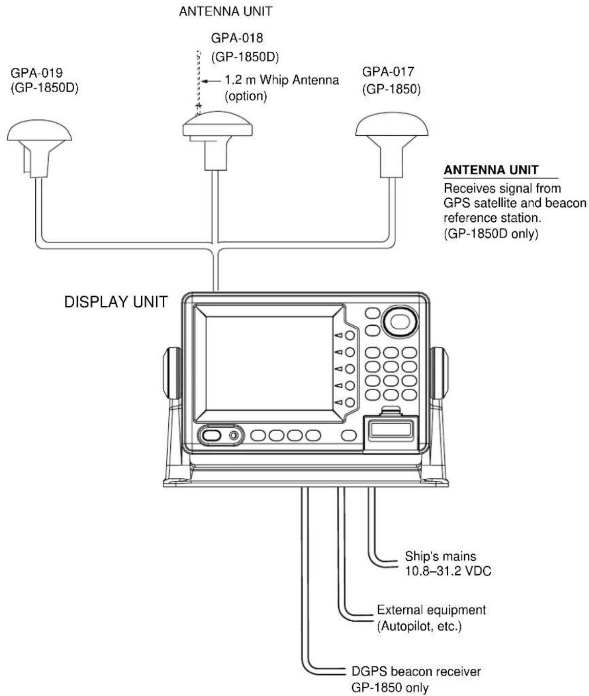
The GP-1850D is a totally integrated DGPS beacon receiver, GPS receiver, and color video plotter. The GP-1850 mostly shares the same features with the GP-1850D except it does not have a built-in DGPS beacon receiver.
Navigation information is displayed on a bright 6.5-inch color TFT LCD. On-screen information shown are position, range and bearing to cursor position, range, bearing, ETA and TTG to waypoint, etc.
A high sensitivity receiver tracks up to twelve satellites simultaneously. An 8-state Kalman filter ensures optimum accuracy in determination of vessel position, course and speed. C-MAP NT-FP chart card is available for the GP-1850/1850D C-MAP NT.
The main features of the GP-1850D/GP-1850 are
- Comprehensive navigation data displays.
- Bright 6.5-inch color TFT LCD with temperature compensated tone and brilliance control.
• Automatic coastline chart loading. - Position display in latitude and longitude, Loran C or Decca TDs.
- Improved position accuracy with optional DGPS beacon receiver (GP-1850).
- Accepts both FURUNO and NAVIONICS or C-MAP NT mini chart cards.
- Alarms: Arrival, Anchor Watch, Cross-track Error, Speed, Proximity.
- Man overboard feature records latitude and longitude coordinates at time of man overboard.
- "Highway" display provides graphic presentation of ship's track and is useful for monitoring cross track error.
This chapter acquaints you with the basics of your unit - from turning on the power to the soft key menu operation.
1.1 Display Unit Controls
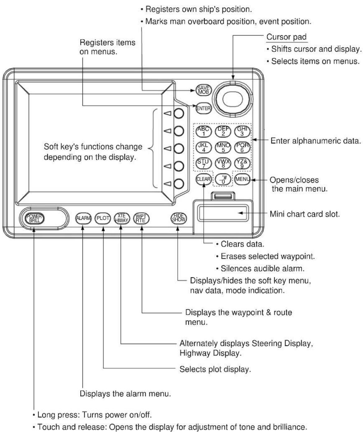
Figure 1-1 Display unit
1.2 Remote Controller
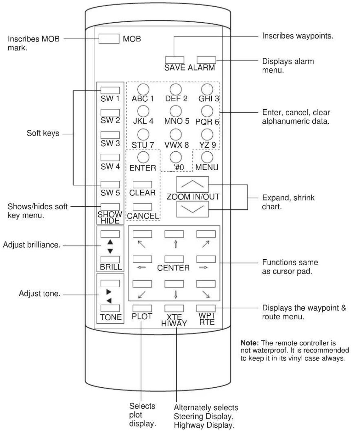
Figure 1-2 Remote controller
1.3 Inserting Mini Chart Card
Insert appropriate mini chart card before turning on the power.
- Push down the lid catch to open the mini chart card slot cover.
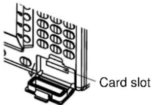
Figure 1-3 Location of mini chart card slot cover
- Insert appropriate mini chart card groove side up.
- Close the slot cover to protect the chart drive. (Keep the slot cover closed at all times.)
Note: Turn off power before inserting or ejecting the mini chart card.
1.4 Turning the Power On/Off
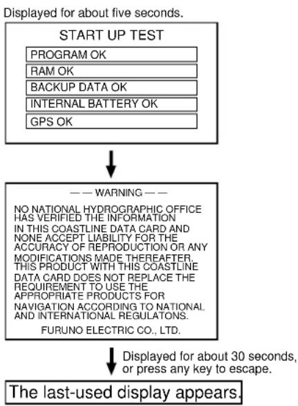
Press the [POWER/BRILL] key at bottom left-hand side of the display unit to turn on the power. When the unit is turned on, it proceeds in the sequence shown in Figure 1-4, after displaying the FURUNO information display.
flowchart
graph TD
    A["START UP TEST"] --> B["PROGRAM OK"]
    A --> C["RAM OK"]
    A --> D["BACKUP DATA OK"]
    A --> E["INTERNAL BATTERY OK"]
    A --> F["GPS OK"]
    B --> G["--- WARNING ---"]
    C --> G
    D --> G
    E --> G
    F --> G
    G --> H["NO NATIONAL HYDROGRAPHIC OFFICE HAS VERIFIED THE INFORMATION IN THIS COASTLINE DATA CARD AND NONE ACCEPT LIABILITY FOR THE ACCURACY OF REPRODUCTION OR ANY MODIFICATIONS MADE THEREAFTER. THIS PRODUCT WITH THIS COASTLINE DATA CARD DOES NOT REPLACE THE REQUIREMENT TO USE THE APPROPRIATE PRODUCTS FOR NAVIGATION ACCORDING TO NATIONAL AND INTERNATIONAL REGULATONS.<br>FURUNO ELECTRIC CO., LTD."]
    H --> I["Displayed for about 30 seconds, or press any key to escape."]
    I --> J["The last-used display appears."]
Figure 1-4 Start-up sequence
Your equipment takes about 90 seconds to find its position when turned on for the very first time. This is because the equipment has no satellite data, called the Almanac, in its database. If you want to lessen the time needed to find position you may enter your position manually (default position: San Francisco, USA) on the GPS SETUP OPTIONS menu.
Thereafter it takes about 12 seconds to find position each time the power is turned on.
When the satellite signal is being received normally, the equipment displays various abbreviations at the bottom left-hand corner of the display which show DGPS/GPS receiver status. Table 1-1 shows these abbreviations and their meanings.
Table 1-1 Display abbreviations
| Indication | Meaning |
| GPS 2D | Normal 2D (dimension) GPS position fix |
| GPS 3D | Normal 3D GPS position fix |
| DGPS 2D0BP- | Normal 2D differential GPS position fix |
| DGPS 3D0BP- | Normal 3D differential GPS position fix |
| NO FIX | Position can not be dnufo |
| DOP | DOP error |
| DEMO | Simulation mode |
Turning the power off
Press and hold down the [POWER/BRILL] key until the screen goes blank. The time remaining until the power is turned off is shown on the screen.
1.5 Adjusting Tone and Brilliance
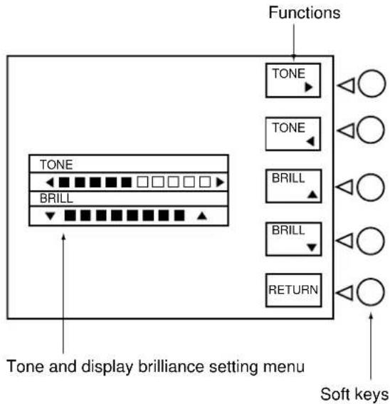
- Press the [POWER/BRILL] key with a touch-and-release action. The tone and brilliance adjustment screen appears.
flowchart
graph TD
    A["Functions"] --> B["TONE"]
    B --> C["BRILL"]
    C --> D["RETURN"]
    E["Tone and display brilliance setting menu"] --> F["Soft keys"]
Figure 1-5 Tone and brilliance setting adjustment screen
- Press ◀ or ▶ to adjust display tone.
- Press ▲ or ▼ to adjust display brilliance.
Note that tone and brilliance can also be adjusted by soft keys. After pressing the [POWER/BRILL] key, use the appropriate soft key to adjust tone or brilliance.
Note: Tone or brilliance must be adjusted within 10 seconds after pressing the [POWER/BRILL] key or the tone and brilliance adjustment screen will be erased.
1.6 Displays
There are four types of plotter displays: Plotter display, Navigation data display, Steering display and Highway display. For details, refer to Chapter 2.
Plotter display, Navigation data display
Press the [PLOT] key to display the Plotter display and Navigation data display alternately.
![[Plotter Display] Press the [PLOT] key. DATE: OCT 21 1998 TIME 23:59:59 POSITION TRIP:123nm 34° 56.789' N 135° 56.789' E SPD 16.3 kt CSE 245.8° RNG 27.2 nm BRG 245.0° DATUM: WGS-84 TMP 68.8°F DEP 20.8ft DGPS 3D [Nav Data Display] Press the [PLOT] key.](/content/2026/05/990451/images/158fc93b08a0f0b3f36d2af16ba42a87ebbe704e904ae7cf1913938f55bd8490.jpg)
Figure 1-6 Display modes (plotter)
Steering display, Highway display
Press the [XTE/HIWAY] key to display the Steering display, Highway display alternately.
![QP < 01 > CROSS TRACK 260250240230 BRG 245.0° RNG 27.2 nm CSE 234.5° SPD 13.6 kt TTG 1h 59m 29th E3A XTE 000.02nm 0.1NM0.1NM DGPS 3D EDIT XT-LMT [Steering Display] 001WPT BRG 94.6nm HIGHWAY CSE 87.8i RNG 1.88nm SPD 10.0kt YUUKI 001WPT FISH01 XTE 000.02nm 0.1NM0.1NM DGPS 3D EDIT XT-LMT [Highway Display]](/content/2026/05/990451/images/1a78782c528abcb24eb6c4f19297328d6192e6b0758f528e5af7608ae6ffbde1.jpg)
Figure 1-7 Steering display, Highway display
1.7 Menu Operation, Soft Keys
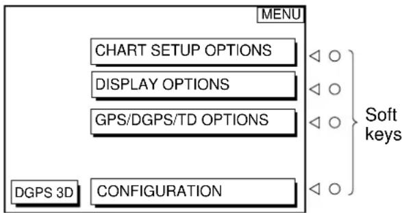
Most operations are carried out through the menu. The menu is opened and closed with the [MENU] key. Menus may be selected with the five soft keys to the right of menus. Options are selected with the cursor pad.
- Press the [MENU] key to display the main menu.
flowchart
graph TD
    A["MENU"] --> B["CHART SETUP OPTIONS"]
    A --> C["DISPLAY OPTIONS"]
    A --> D["GPS/DGPS/TD OPTIONS"]
    A --> E["DGPS 3D CONFIGURATION"]
    style A fill:#f9f,stroke:#333
    style B fill:#ccf,stroke:#333
    style C fill:#ccf,stroke:#333
    style D fill:#ccf,stroke:#333
    style E fill:#ccf,stroke:#333
    note right of A Soft keys
    note right of A Soft keys
Figure 1-8 Main menu
- Press appropriate soft key to display desired menu. For example, press the soft key CHART SETUP OPTIONS. The menu in use appears at the top right corner of the display.
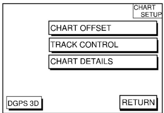
Figure 1-9 Chart setup options menu
- Select menu with the soft keys. For examples press the soft key TRACK CONTROL to display the track control menu.
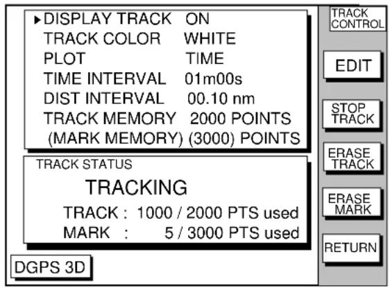
Figure 1-10 Track control menu
- Use the cursor pad to select item, and then press the soft key EDIT. For example, select TRACK COLOR. The track color window appears.
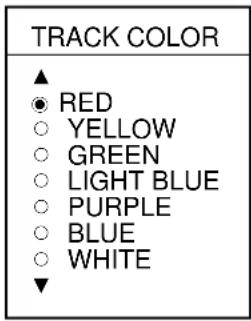
Figure 1-11 Track color window
- Use the cursor pad to select option.
- Press the soft key RETURN to finish.
1.8 Demonstration Display
The demonstration display provides simulated operation of this unit. On the plotter display, own ship tracks, at the speed selected, a figure eight course or any course you enter, starting from position entered. All controls are operative; you may set destination, enter waypoints, etc.
- Press the [MENU] key, followed by the soft keys CONFIGURATION and SYSTEM MENU to open the system menu.
- Press the soft key DEMONSTRATION MODE to open the demonstration setting screen.
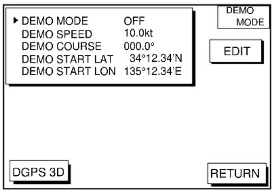
Figure 1-12 Demo setting screen
- Press ▲ or ▼ to select DEMO MODE.
- Press the soft key labeled EDIT to show the demo mode window.
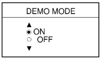
Figure 1-12 Demo mode window
- Press ▲ to select ON.
- Press the soft key ENTER or the [ENTER] key.
- Select DEMO SPEED and press the soft key EDIT. Enter speed with the cursor pad. Select digit with ◀/▶ and enter value with numeric key.
- Select DEMO COURSE and press the soft key EDIT. Select how you want the courseline to be traced; by FIGURE 8 or DIR.(ection). For DIR., enter course.
- Select DEMO START LAT., and press the soft key EDIT. Enter current latitude.
- Select DEMO START LONG., and press the soft key EDIT. Enter current longitude.
- Press the soft key RETURN to finish.
To cancel the demonstration display, set DEMO MODE to OFF.
2.1 Presentation Modes
The plotter display mainly shows chart, ship's track, waypoints, and navigation data.
Three types of display presentations are provided for the normal plotter display: north-up, course-up and auto course-up. To change the mode, use the presentation mode selection soft key, which is the 3rd soft key from the top.
North-up
Press the soft key NORTH UP to show the north-up display. North (zero degree) is at the top of the display and own ship is at the center of the screen. Own ship marker is a filled circle. This mode is useful for long-range navigation.
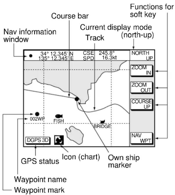
Figure 2-1 Plotter display, north-up mode
Course-up
Press the soft key COURSE UP to show the course-up display. When destination is set it is at the top of the screen, the north mark appears at the upper left side of the screen and points to north. A filled triangle marks own ship's position.
When destination is not set, the course or heading is upward on the screen at the moment the course-up mode is selected.
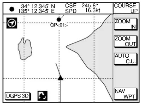
Figure 2-2 Plotter display, course-up mode
Auto course-up
Press the soft key AUTO C.U. to show the automatic course-up display. The course or heading is at the top of screen at the moment the course-up mode is selected. When own ship is off its intended course by 22.5° or more, it is automatically brought back to perpendicular.
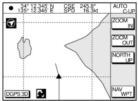
Figure 2-3 Auto course-up mode
2.2 Cursor
Turning on the cursor, shifting the cursor
Press the cursor pad to turn the cursor on, and the cursor appears at the own ship's position. Operate the cursor pad to shift the cursor. The cursor moves in the direction of the arrow or diagonal pressed on the cursor pad.
Cursor state determines what data is shown on the display. Cursor position is displayed in latitude and longitude or Loran or Decca TDs (depending on menu setting) at the top of the plotter display when the cursor is on.
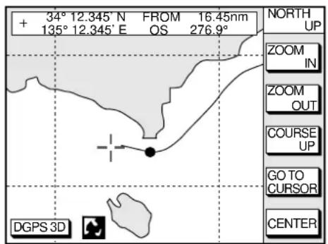
Figure 2-4 Data displayed on the plotter display when the cursor is on
Turning off the cursor, returning own ship marker to screen center
The soft key CENTER turns off the cursor and returns own ship marker to screen center.
2.3 Shifting the Display
The display can be shifted on the plotter display.
- Press the cursor pad to display the cursor.
- Locate the cursor at a screen edge. The screen shifts in the direction opposite of cursor location.
2.4 Selecting Chart Scale/Range
Chart scale (range) may be selected with the soft key ZOOM IN or ZOOM OUT. ZOOM IN expands the chart; ZOOM OUT shrinks it.
Note: When the display is expanded or shrunk beyond the range of the chart card in use NO CHART appears, along with the appropriate chart icon. See Table 2-1.
2.5 Mini Chart Cards
The mini chart cards contain nautical charts. When you insert a suitable mini chart card in the slot and your boat is near land, a chart appears.
When a wrong card is inserted or a wrong chart scale is selected, the land will be hollow. Insert the proper card and select a suitable chart scale. Chart icons appear to help you select a suitable chart scale. Table 2-1 shows the chart icons and their meanings.
Table 2-1 Chart icons and their meanings
| Icon Meaning | |
 | Proper card is not inserted or chart scale is too small. Press the soft key ZOOM IN to adjust chart scale. |
 | Chart scale is too large. Press the soft key ZOOM OUT to adjust chart scale. |
 | Suitable chart scale is selected. |
Indices and chart enlargement
When the soft key ZOOM OUT is used, you will see several frames appear on the chart. These frames are called indices and they show you what parts of the chart can be enlarged in the current picture range. The areas circumscribed with smaller frames can be enlarged, but the area enclosed by the largest frame cannot.
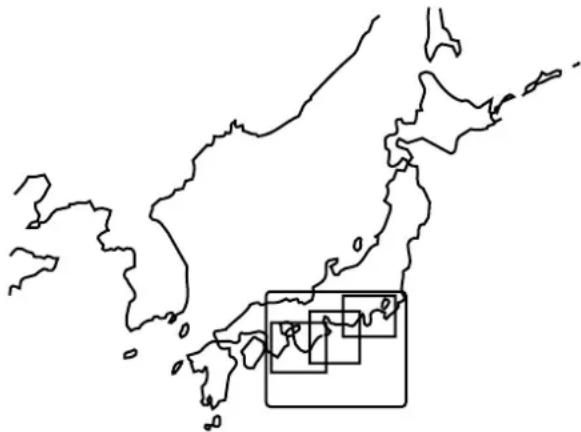
natural_image
Outline map of Japan with a zoomed-in inset showing regional data (no text or labels)Figure 2-5 Sample chart (Japan and South Korea) showing indices
Remarks on chart display
A chart will not be displayed in the following conditions:
- When the chart scale is too large or too small.
- When scrolling the chart outside the indices.
When this happens, select proper chart scale.
Chart symbols
The table below shows FURUNO mini chart symbols and their meanings.
Table 2-2 FURUNO chart symbols
| Symbol | Description |
 | Summit |
| [YZSW] | Wreck |
 | Lighthouse |
 | Lighted Buoy |
 | Buoy |
 | Radio Station |
| [389Y] | Position of Sounding |
 | Obstruction |
 | Fishing Reef |
| [T50K] | Platform |
 | Anchorage |
Table 2-3 Comparison of FURUNO and Nav-Charts™ chart cards
| Item | FURUNO | Nav-ChartsTM |
| gitistoDipapac | SEY | ES |
| pu-esruoCyalpid | SEY | ES |
| atadehthgilndateerp | $E | ES |
| Zoom at cursorsdip | ES | *1 |
| taegnaRrotaEq | ,5.08402.,12 | af68a |
| dtfotrahyrtneatad | YES | YES |
| Centering | YES | *2 |
*1 Nav-Charts™ chart may not center the cursor perfectly.
*2 Nav-Charts™ chart may not center own ship's position perfectly.
*3 Newly designed chart cards containing lighthouse data. Chart cards for North America area are completed, and others are in production.
*4 Nav-Charts™ is the registered trademark of NAVIONICS INC.
Aid to navigation data
Selected FURUNO and Nav-Charts™ mini chart cards can show buoy and lighthouse data. Simply place the cursor on the lighthouse or buoy mark.

Place the cursor on a lighthouse or buoy mark.
Figure 2-6 Placing the cursor on the mark
Example of data displayed
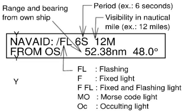
Figure 2-7 Example of buoy, lighthouse data
Port service icons (Nav-Charts™ cards)
Selected Nav-Charts™ mini chart cards show by icons services available at ports. Use the cursor pad to place the cursor on the sailboat icon (denotes a port or harbor), and then press the [ENTER] key. The services available appear at the top of the display.
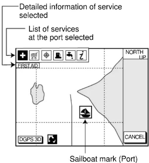
Figure 2-8 Plotter display showing Nav-Charts™ port service display

Emergency
medical service

Fueling station

Water
supply station

Traveler's
service station
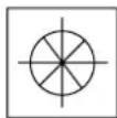
Customer
service station
Marine
equipment service

Port

Information center
Figure 2-9 Port service icons
2.6 Navigation Data Display
The navigation data display provides generic navigation data and DPGS/GPS information. Press the [PLOT] several times to show the navigation data display.
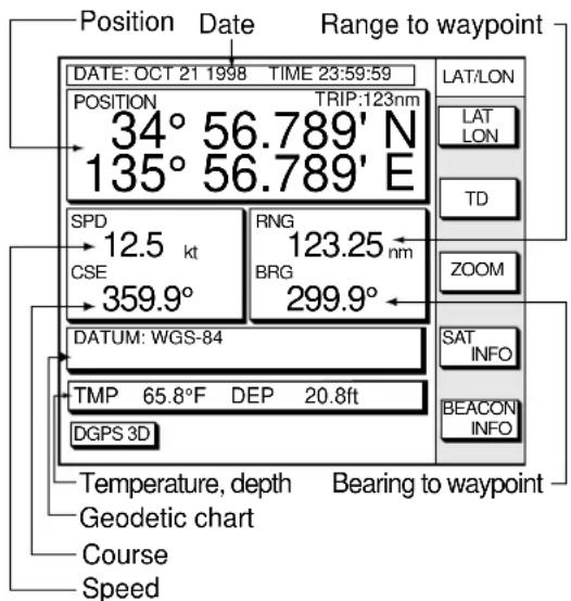
Figure 2-10 Navigation data display
Navigation data display shows the position by L/L or TD (Loran-C, Decca). To change position format, press the appropriate soft key LAT/LON or TD.
Enlarging an indication
An indication on the screen may be enlarged as follows:
-
Use the cursor pad to select the indication which you wish to enlarge. Selected indication is circumscribed with a red cursor.
-
Press the soft key ZOOM.
To return to the normal nav data display, press the soft key RETURN.
GPS satellite monitor display
The GPS satellite monitor display shows information about GPS satellites.
Press the soft key SAT INFO. Your display should look something like the following illustration.
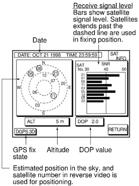
Figure 2-11 GPS satellite monitor display
To return to the normal navigation data display, press the soft key RETURN.
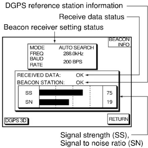
Beacon information display
Equipped with a DGPS beacon receiver, your unit can show DGPS reference station information. Press the soft key BEACON INFO to show the DGPS reference station information.
flowchart
graph TD
    A["DGPS reference station information"] --> B["Receive data status"]
    B --> C["Beacon receiver setting status"]
    C --> D["MODE AUTO SEARCH"]
    D --> E["FREQ 288.0kHz"]
    E --> F["BAUD 200 BPS"]
    F --> G["RATE"]
    G --> H["BEACON INFO"]
    I["RECEIVED DATA: OK"] --> J["SS 75"]
    I --> K["SN 19"]
    L["BEACON STATION: OK"] --> M["Signal strength (SS), Signal to noise ratio (SN)"]
    N["DGPS 3D"] --> O["Return"]
Figure 2-12 Beacon information display
SS: SS (Signal Strength) displays a numeric representation of field strength of the received signal on the selected frequency. The higher the number the stronger the received signal. If noise is present at reception band width, the figure gets bigger.
SN: SN (Signal-to-Noise) ratio displays the ratio between the desired signal and unwanted noise on the selected frequency. The higher the SN ratio the better the quality of the signal.
Note: If your equipment does not have a DPGS receiver, the message "NO DIFFERENTIAL DATA" appears when the soft key BEACON INFO is pressed.
2.7 Steering Display
The steering display provides steering information such as range, bearing, ETA to destination, course and speed.
Press the [XTE/HIWAY] key to show the steering display.
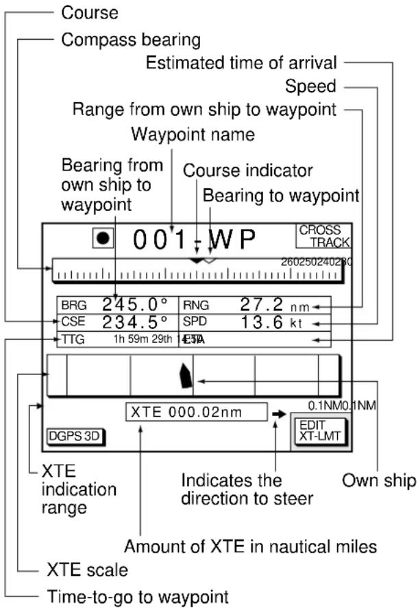
Figure 2-13 Steering display
How to read the compass display
The solid inverted triangle at the center of the compass shows own ship's course (heading). The hollow inverted triangle shows the bearing to destination waypoint. When own ship's course is changed, the hollow inverted triangle moves with course change.
How to read the XTE scale
The black boat-shaped mark shows own boat's movement and direction, and amount to steer to return to course. Using Figure 2-13 as an example, you would steer right by 000.02 nautical miles to return to course. When this mark is out of range of the XTE scale, the mark color changes from black to yellow. The range of the XTE scale can be set as shown below (default: 0.5 nm).
Setting the range of the XTE scale
- Press the soft key EDIT XT-LMT to display the following window.
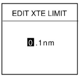
Figure 2-14 XTE range setting window
- Use the cursor pad to select digit to change.
- Press appropriate alphanumeric key.
- Repeat steps 2 and 3.
- Press the [ENTER] key. To cancel entry, press the soft key CANCEL.
Note that all digits may be cleared by pressing the [CLEAR] key.
2.8 Highway Display
The highway display provides a graphic presentation of ship's track along intended course. It is useful for monitoring XTE - the XTE scale shows direction and amount in nautical miles to steer to return to course. In the figure below, for example, you would steer right by 0.02 nm to return to course.
Press the [XTE/HIWAY] key to show the highway display.
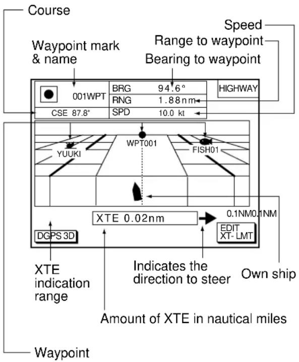
Figure 2-15 Highway display
2.9 Changing Operation Mode
Operation mode can be changed between PLEASURE and FISHING. FISHING mode provides mark/line entry on the PLOTTER display. The mark can be entered up to 5000 points together with tracks. The apportion between track and mark memory can be changed at menu. Pressing the [HIDE/SHOW] key changes the function of soft keys. Holding track, changing track color, and selecting color and form of mark/line can be performed by the soft keys directly.
- Press the [MENU] key and the soft key DISPLAY OPTIONS. The display setup1 menu appears.
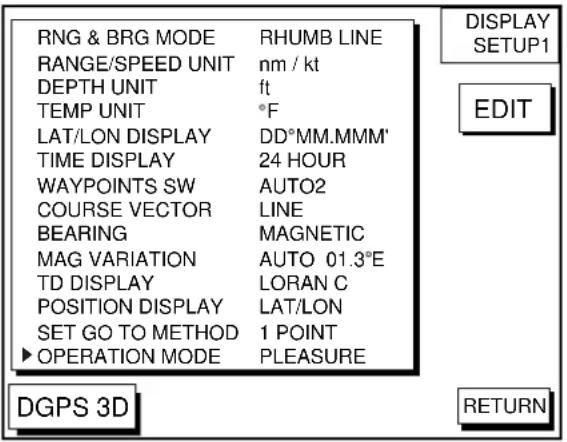
Figure 2-16 Display setup1 menu
- Press ▼ to select OPERATION MODE.
- Press the soft key EDIT to show the OPERATION MODE window.
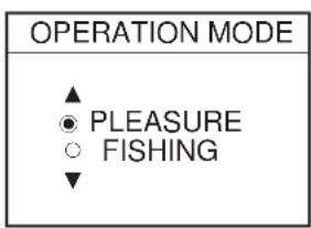
- Press ▲ or ▼ to select PLEASURE or FISHING.
- Press the soft key ENTER or the [ENTER] key to finish.
2.10 Navigation Trip Distance
The navigation trip distance is displayed at the navigation data display. Press the [PLOT] key several times to show the navigation data display.
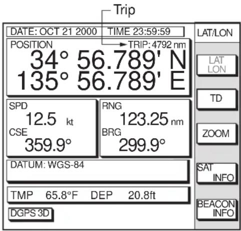
Figure 2-18 Navigation data display
Note: When you enlarge POSITION, TRIP is not displayed.
You can reset the trip distance as follows.
- Press the [MENU] key followed by the soft keys CONFIGURATION and SYSTEM MENU.
- Press the soft key MEMORY/TRIP CLEAR to open the clear memory menu.
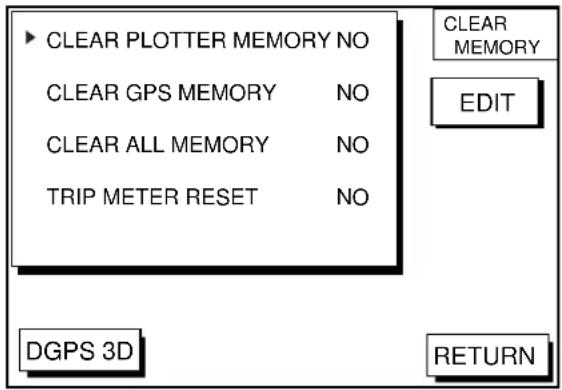
Figure 2-19 Clear memory menu
- Press ▼ to select TRIP METER RESET.
- Press the soft key EDIT.
- Press ▲ to select YES.
- Press the soft key ENTER or the [ENTER] key to clear memory selected.
3.1 Displaying Track
- Press the [MENU] key to open the main menu.
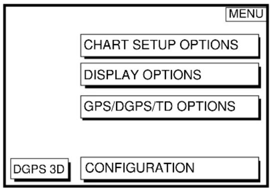
Figure 3-1 Main menu
- Press the soft key CHART SETUP OPTIONS to open the chart setup menu.
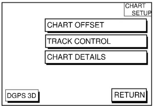
Figure 3-2 Chart setup menu
- Press the soft key TRACK CONTROL to open the track control menu.
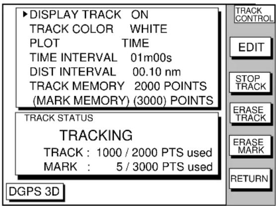
Figure 3-3 Track control menu
- Press ▲ to select DISPLAY TRACK.
- Press the soft key EDIT to show the display track window.
- Press ▲ or ▼ to select ON or OFF as appropriate.
- Press the soft key ENTER or the [ENTER] key.
- Press the [PLOT] key to close the menu.
The default setting is ON which traces ship's track in accordance with ship's movements.
Number of track and mark points used appears at the TRACK STATUS window on the TRACK CONTROL display. In case of figure 3-3, track memory is recorded 1000 points (max. 2000 points) and mark memory is recorded 5 points (max. 3000 points).
3.2 Stopping/Restarting Plotting of Track
When your boat is at anchor or returning to port you probably won't need to record its track. You can stop recording the track, to conserve the track memory, as follows:
- Press the [MENU] key followed by the soft keys CHART SETUP OPTIONS and TRACK CONTROL.
- Press the soft key STOP TRACK. The indication "TRACKING" in the TRACK STATUS window changes to "NOT TRACKING".
To restart recording the track, press the soft key START TRACK at step 2 in the above procedure.
When the fishing mode is selected, you can stop or restart plotting the track with the soft key only on the plotter display. Press the [SHOW/HIDE] key several times to show the soft key STOP TRACK. Press the soft key STOP TRACK on the plotter display to stop plotting of track. HOLD TRACK PLOTTING appears approx. 2 seconds and own ship mark changes to hollow circle. To restart plotting the track, press the soft key START TRACK. START TRACK PLOTTING appears approx. 2 seconds and the plotting restarts.
3.3 Changing Track Color
Track can be displayed in red, yellow, green, light-blue, purple, blue or white. It can be useful to change track color on a regular basis to discriminate between previous day's track, past track, etc.
- Press the [MENU] key followed by the soft keys CHART SETUP OPTIONS and TRACK CONTROL.
- Press ▲ or ▼ to select TRACK COLOR.
- Press the soft key EDIT to display the track color window.
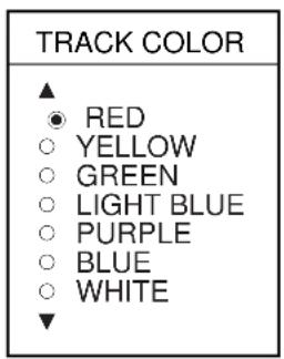
Figure 3-4 Track color window
- Press ▲ or ▼ to select the color desired.
- Press the soft key ENTER to finish.
When the fishing mode is selected, you can change track color with the soft key only on the track display.
- Press the [SHOW/HIDE] key several times to show the soft key TRACK COLOR.
- Press the soft key TRACK COLOR to show the TRACK COLOR window.
- Press ▲ or ▼ to select the color desired.
- Press the soft key ENTER or the [ENTER] key to finish, or press the soft key CAN-CEL to escape.
3.4 Track Plotting Method, Interval
In drawing the track, first the ship's position (fed from the DGPS/GPS receiver) is stored into the unit's memory at an interval of time or distance. A shorter interval provides better reconstruction of the track, but the storage time of the track is reduced. When the track memory becomes full, the oldest track is erased to make room for the latest.
Track plotting method
- Press the [MENU] key followed by the soft keys CHART SETUP OPTIONS and TRACK CONTROL.
- Press ▲ or ▼ to select PLOT.
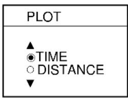
- Press the soft key EDIT to display the plot window.
flowchart
graph TD
    A["PLOT"] --> B["▲"]
    A --> C["●TIME"]
    A --> D["○DISTANCE"]
    A --> E["▼"]
Figure 3-5 Plot window
- Press ▲ or ▼ to select TIME or DISTANCE. Distance is useful for conserving track memory, since no track is recorded when the boat is stationary.
- Press the soft key ENTER or the [ENTER] key.
Track plotting interval
- Press the [MENU] key followed by the soft keys CHART SETUP OPTIONS and TRACK CONTROL.
- Press ▲ or ▼ to select TIME INTERVAL or DIST INTERVAL.
- Press the soft key EDIT to display the interval window.
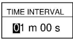
(When selecting TIME INTERVAL.)
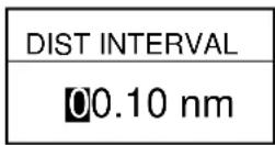
(When selecting DIST INTERVAL.)
Figure 3-6 Interval window
- Use the cursor pad to place the cursor on the digit desired. The [CLEAR] key functions to clear an entire line of data.
- Press appropriate alphanumeric key to enter value.
- Repeat steps 4 and 5 to complete.
- Press the soft key ENTER or the [ENTER] key.
3.5 Changing Track Memory Capacity
The equipment stores a total of 5000 points of track and marks. This total may be freely apportioned as desired. The default setting is 2000 points of track and 3000 marks. You can change the memory capacity for track and marks. Note that when this is done all tracks and marks in the memory are erased.
- Press the [MENU] key followed by the soft keys CHART SETUP OPTIONS and TRACK CONTROL.
- Press ▼ to select TRACK MEMORY.
- Press the soft key EDIT to display the TRACK MEMORY window.
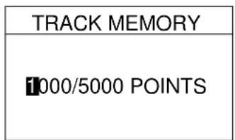
Figure 3-7 TRACK MEMORY window
The TRACK MEMORY window may be erased by pressing the soft key CANCEL to escape.
- Enter number of track memory points desired with the alphanumeric keys.
Note that all digits may be cleared by pressing the soft key CLEAR or the [CLEAR] key in entering track memory points.
- Press the soft key ENTER or the [ENTER] key. The following window appears to ask you if you are sure to change the track memory capacity.
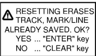
Figure 3-8 ERASE messege
- Press the [ENTER] key to change apportion, or press the [CLEAR] key to escape.
3.6 Erasing All Track
You can erase all track. Be absolutely sure you want to erase all track; erased track cannot be restored.
- Press the [MENU] key followed by the soft keys CHART SETUP OPTIONS and TRACK CONTROL.
- Press the soft key ERASE TRACK. You are asked if you sure to erase all track.
- Press the [ENTER] key to erase, or press the [CLEAR] key to escape.
4.1 Entering Marks
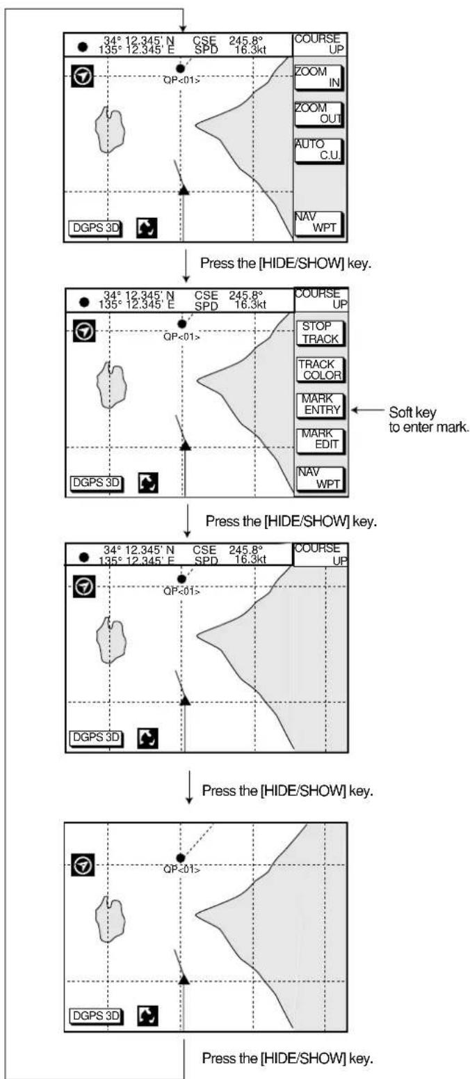
Select the fishing mode to enable entry of marks on the PLOTTER display. Select the location desired with the cursor, or turn off the cursor to enter the mark at own ship position. Pressing the [HIDE/SHOW] key changes the function of the soft keys. Press the soft key MARK ENTRY to enter the mark. The mark is entered in the shape and color selected from the MARK SHAPE and MARK COLOR windows.
In the FISHING mode, pressing the [HIDE/SHOW] key changes the function of the soft keys as follows.
flowchart
graph TD
    A["Start"] --> B["Check Point"]
    B --> C{Check Key}
    C -->|Yes| D["Check Course UP"]
    C -->|No| E["Check Stop Track"]
    D --> F["Check Track OUT"]
    E --> G["Check Mark Entry"]
    F --> H["Check Mark Edit"]
    G --> I["Check Mark WPT"]
    H --> J["Check Course UP"]
    I --> K["Check Course UP"]
    J --> L["Check Course UP"]
    K --> M["Check Course UP"]
    L --> N["Check Course UP"]
    M --> O["Check Course UP"]
    N --> P["Check Course UP"]
    O --> Q["Check Course UP"]
    P --> R["Check Course UP"]
    Q --> S["Check Course UP"]
    R --> T["Check Course UP"]
    S --> U["Check Course UP"]
    T --> V["Check Course UP"]
    U --> W["Check Course UP"]
    V --> X["Check Course UP"]
    W --> Y["Check Course UP"]
    X --> Z["Check Course UP"]
    Y --> AA["Check Course UP"]
    Z --> AB["Check Course UP"]
Figure 4-1 Changing Display
4.2 Changing Mark Attributes
You can select shape, line and color of mark/line on the TRACK display.
- Press the [HIDE/SHOW] key to show the soft key MARK EDIT.
- Press the soft key MARK EDIT to show the MARK/LINE window.
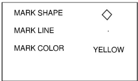
Figure 4-2 MARK/LINE window
- Press the soft key MARK SHAPE to change mark shape, the soft key MARK LINE to change mark line, or the soft key MARK COLOR to change mark color.
Mark shape
Press the soft key MARK SHAPE to display the MARK SHAPE window. Press ▲ or ▼ to select mark shape desired.
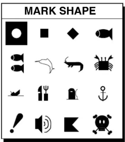
Figure 4-3 MARK SHAPE window
Mark line
Press the soft key MARK LINE to display the MARK LINE window. Press ▲ or ▼ to select mark line desired.
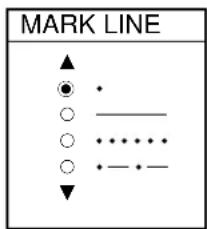
Figure 4-4 MARK LINE window
Mark color
Press the soft key MARK COLOR to display the MARK COLOR window. Press ▲ or ▼ to select mark color desired.
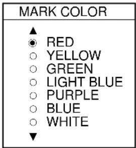
- Press the soft key ENTER or the [ENTER] key.
- Press the soft key RETURN to finish.
Marks/lines entered hereafter are inscribed in the shape, color and line type selected here.
4.3 Changing Mark Size
Mark size can be selected from STD (standard) and SMALL.
- Press the [MENU] key to display the main menu.
- Press the soft key CHART SETUP OPTIONS.
- Press the soft key CHART DETAILS to open the CHART DETAILS menu.
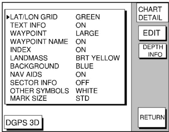
Figure 4-6 CHART DETAILS menu
- Press ▼ to select MARK SIZE.
5 Press the soft key EDIT. - Press ▲ or ▼ to select STD (standard) or SMALL.
- Press the [ENTER] key.
4.4 Erasing Marks
Erasing individual marks/lines
- Operate the cursor pad to place the cursor on the mark you want to erase.
- Press the [CLEAR] key. The mark selected is erased.
Note: To erase line, place the cursor on a edge of the line. The line segment will be erased.
Erasing whole marks/lines
You can erase all marks and lines. Be absolutely sure you want to erase all marks and lines; erased marks and lines cannot be restored.
- Press the [MENU] key followed by the soft keys CHART SETUP OPTIONS and TRACK CONTROL.
- Press the soft key ERASE MARK. You are asked if you are sure to erase all marks and lines.
- Press the [ENTER] key to erase, or press the [CLEAR] key to escape.
4.5 Displaying Track and Mark Points
Number of track and mark points used appears in the TRACK STATUS window on the TRACK CONTROL display. For further details see page 3-1.
5.1 Entering Waypoints
In navigation terminology, a waypoint is a particular location on a voyage whether it be a starting, intermediate or destination point. A waypoint is the simplest piece of information your equipment requires to get you to a destination, in the shortest distance possible.
This unit has 835 waypoints (including quick waypoints) into which you can enter position information. There are five methods by which you can enter a waypoint: at own ship's position, at MOB position, by cursor, by range and bearing, and through the waypoint list (manual input of latitude and longitude).
Entering waypoints at own ship's position
You can save your current position as a waypoint. Press the [SAVE/MOB] key with a touch-and-release action to store your position. This new waypoint will automatically be saved in the waypoint list under the next consecutive waypoint number.
Entering waypoints at MOB position
The MOB mark functions to mark man over-board position.
- Press the [SAVE/MOB] key several seconds to display the following message.
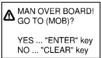
Figure 5-1 MOB message
- Press the [ENTER] key to select MOB position as destination, or the [CLEAR] key to only mark MOB position.
- To show range and bearing to the MOB position, press the soft key NAV L/L followed by the soft key NAV WPT.
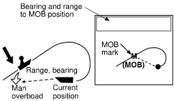
flowchart
graph TD
    A["Man overload"] --> B["Range, bearing"]
    B --> C["Current position"]
    D["Bearing and range to MOB position"] --> E["MOB mark M (MOB)"]
    style A fill:#f9f,stroke:#333
    style B fill:#ccf,stroke:#333
    style C fill:#cfc,stroke:#333
    style D fill:#fcc,stroke:#333
    style E fill:#cff,stroke:#333
Figure 5-2 MOB concept
To erase a MOB mark, you must erase both the waypoint it is registered under and the MOB mark itself. Place the cursor on the MOB mark and press the [CLEAR] key followed by the [ENTER] key to erase the waypoint. (A flashing diamond appears over the waypoint when it has been correctly selected.) Repeat to erase the MOB mark.
Entering waypoints by the cursor
- Press the [WPT/RTE] key to open the waypoint & route menu.
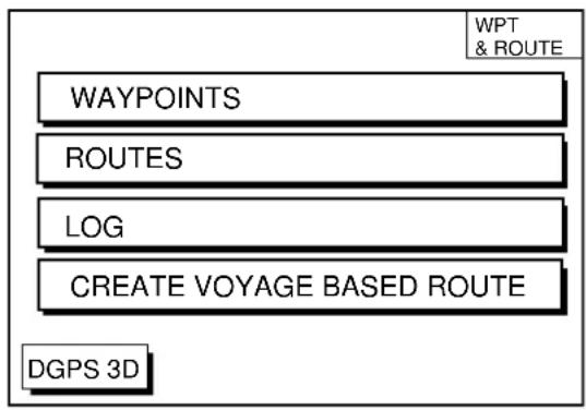
Figure 5-3 Waypoint & route menu
- Press the soft key WAYPOINTS to display the waypoint menu.
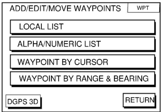
Figure 5-4 waypoint menu
- Press the soft key WAYPOINT BY CURSOR. The plotter display appears.
- Operate the cursor pad to place the cursor on the location desired.
- Press the soft key NEW WPT. The waypoint window appears and it shows mark shape, waypoint name, comment (default: date), position of waypoint and proximity alarm radius.
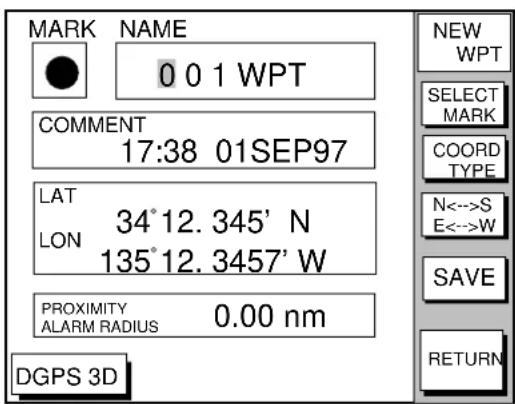
Figure 5-5 Waypoint window
- If you do not need to change the waypoint data, simply press the soft key SAVE to register the waypoint and return to the plotter display. Be sure to press the soft key SAVE only after changing all data.
Changing the shape and color of waypoint mark
- Press the soft key SELECT MARK.
- Press the soft key MARK SHAPE to open the mark shape selection window.
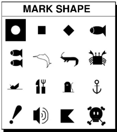
Figure 5-6 Mark shape selection window
- Operate the cursor pad to select shape desired.
- Press the soft key ENTER or the [ENTER] key.
- Press the soft key SELECT MARK.
- Press the soft key MARK COLOR to open the mark color selection window.
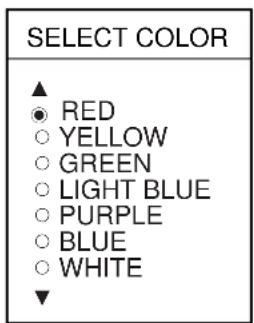
Figure 5-7 Mark color selection window
- Press ▲ or ▼ to select the color desired, and then press the soft key ENTER or the [ENTER] key.
Changing waypoint name, comment, proximity alarm radius
- If necessary, you can change the name (1 to 6 characters), comment (13 characters), L/L position and the proximity alarm radius (explained in detail in Chapter 8) as follows:
a) Select the NAME, COMMENT or PROXIMITY ALARM RADIUS field.
b) Use the cursor pad to select character or digit.
c) Enter appropriate data with the alphanumeric keys.
Note: You cannot change shape and color of a waypoint when it has a proximity alarm radius entered. To change shape or color, enter all zeroes as the proximity alarm radius.
Changing waypoint position
- Use the cursor pad to place the cursor in the LAT LON field.
- Operate the cursor pad to place the cursor on digit to change. Enter appropriate data with the alphanumeric keys.
- You can switch co-ordinates with the soft key N<-->S/E<-->W.
Entering waypoints by range and bearing
This method is useful when you want to enter a waypoint using range and bearing to a target found on a radar.
- Press the [WPT/RTE] key to open the waypoint & route menu.
- Press the soft key WAYPOINTS to open the waypoint menu.
- Press the soft key WAYPOINT BY RANGE & BEARING. The plotter screen appears.
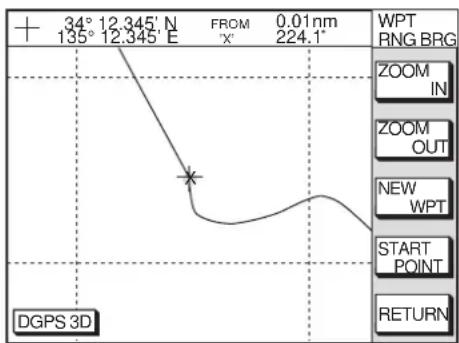
Figure 5-8 Plotter display, Range and bearing selected as waypoint entry method
- Operate the cursor pad to place the cursor on the location desired. The range and bearing from own ship to cursor appear at the top of the screen.
Note: The origin point of range and bearing can be shifted to the place you desire. Operate the cursor pad to select location, and then press the soft key START POINT. "X" appears at the cursor position.
- Press the soft key NEW WPT. The screen should look something like the one shown in Figure 5-5.
- If necessary, change data as you did in "Entering waypoints by the cursor."
- Press the soft key SAVE to register the waypoint.
- Press the [WPT/RTE] key to open the waypoint & route menu.
- Press the soft key WAYPOINTS to open the waypoint menu.
- Press the soft key LOCAL LIST (lists waypoints in order from nearest to furthest) or ALPHA/NUMERIC LIST (lists waypoints in alphanumeric order).
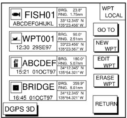
Figure 5-9 Local list
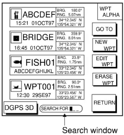
Figure 5-10 Alpha/numeric list
- Press the soft key NEW WPT to show the waypoint window. Own ship's position is shown. Change the data similar to how you did in "Entering waypoints by the cursor."
- Press the soft key SAVE.
5.2 Erasing Individual Waypoints
Individual waypoints can be erased by the cursor or through the waypoint list.
Erasing waypoints by the cursor
- Press the cursor pad to turn on the cursor.
-
Operate the cursor pad to place the cursor on the waypoint you want to erase. A flashing diamond mark appears over the waypoint when it is correctly selected.
-
Press the [CLEAR] key. You are asked if you are sure to erase the waypoint.
- Press the [ENTER] key. The waypoint is erased from both the plotter screen and the waypoint list.
Erasing waypoints through the waypoint list
- Press the [WPT/RTE] key to open the waypoint & route menu.
- Press the soft key WAYPOINTS to open the waypoint menu.
- Press the soft key LOCAL LIST or ALPHA/NUMERIC LIST.
- Press ▲ or ▼ to select the waypoint you want to erase.
- Press the soft key ERASE WPT. You are asked if you are sure to erase the waypoint.
- Press the [ENTER] key. The waypoint is erased from both the waypoint list and the plotter screen.
5.3 Changing Waypoint Data
You can change the waypoint data through the list.
- Press the [WPT/RTE] key, soft key WAYPOINTS, and soft key LOCAL LIST or ALPHA/NUMERIC LIST.
- Press ▲ or ▼ to select the waypoint you want to change.
- Press the soft key EDIT WPT.
- Change data as you did in "Entering waypoints by the cursor."
- Press the soft key SAVE.
5.4 Waypoint Mark Size
You may change the size of all waypoint marks to small or large (default), or turn them off.
- Press the [MENU] key to open the main menu.
- Press the soft key CHART SETUP OPTIONS.
- Press the soft key CHART DETAILS to open the CHART DETAILS menu.
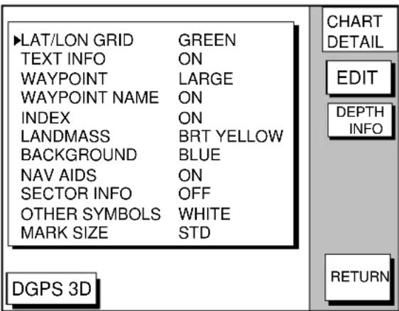
Figure 5-11 Chart details menu
-
Press ▲ or ▼ to select WAYPOINT.
-
Press the soft key EDIT.
-
Press ▲ or ▼ to select LARGE, SMALL or OFF. LARGE shows mark in actual shape. SMALL displays all waypoints with an "X" regardless of mark shape selected.
-
Press the soft key ENTER or [ENTER] key.
5.5 Changing Waypoint Position on the Plotter Display
You may change the latitude and longitude position of waypoints on the plotter display as follows:
-
Press the [WPT/RTE] key followed by the soft key WAYPOINTS to open the waypoint menu.
-
Press the soft key WAYPOINT BY CURSOR. The plotter display appears.
- Operate the cursor pad to place the cursor on the waypoint which you want to change. A flashing diamond mark appears on the waypoint when it is correctly selected.
- Press the soft key EDIT/MOVE.
- Press the soft key MOVE WPT.
- Operate the cursor pad to place the cursor on the location desired.
- Press the [ENTER] key.
The waypoint moves to the cursor position and its new position is recorded on the waypoint list. If the waypoint is set as destination or is part of a route, you are asked if you are sure to move the waypoint. In this case, press the [ENTER] key again, or the [CLEAR] key to cancel move.
5.6 Searching Waypoints
You can search for a waypoint through the alpha/numeric list as follows:
- Press the [WPT/RTE] key, and then press the soft keys WAYPOINTS and ALPHA/NUMERIC LIST to show the alpha/numeric list. At the bottom of the display the search window appears.
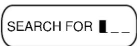
Figure 5-12 Search window
- Use the alphanumeric keys to enter the first 1 - 3 characters in the search window. The waypoint searched appears at the top of the screen.
Often a trip from one place to another involves several course changes, requiring a series of route points (waypoints) which you navigate to, one after another. The sequence of waypoints leading to the ultimate destination is called a route. Your unit can automatically advance to the next waypoint on a route, so you do not have to change the destination waypoint repeatedly.
You can store up to 200 routes. A route may consist of 35 points.
6.1 Entering Routes
Entering routes through the route list
This method constructs routes using existing waypoints.
- Press the [WPT/RTE] key to open the waypoint & route menu.
- Press the soft key ROUTES to open the route menu.
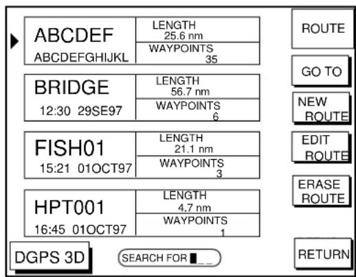
Figure 6-1 Route menu
- Press the soft key NEW ROUTE to open the new route entry screen.
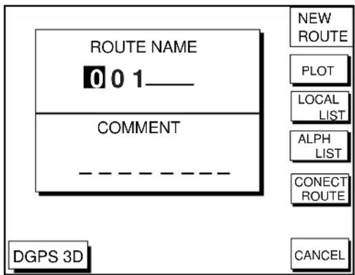
Figure 6-2 New route entry screen
-
If desired you can change the route name shown and/or add a comment. To change route name, press the [CLEAR] key to clear the route name. Use the cursor pad to locate the cursor and then press appropriate alphanumeric key. To enter a comment, place the cursor in the COMMENT window. Use the cursor pad and alphanumeric keys to enter your comment. A route name may consist of six characters; comment, 13 characters.
-
Press the soft key LOCAL LIST or ALPH LIST to open the waypoint list.
-
Press ▲ or ▼ to select a waypoint, and press the soft key ADD WPT to add it to the route.
-
Repeat step 6 to complete the route.
When you want to clear a waypoint selected, press the soft key ERASE LST WP. Each pressing of this key deletes the last waypoint entered.
- Press the soft key SAVE to register the route.
Entering routes by the cursor
This method allows you to construct a route directly on the plotter display, using existing waypoints or new locations. Any new location will be saved as a waypoint, under the next consecutive waypoint number.
- Follow step 1-4 in "Entering routes through the route list."
- Press the soft key PLOT. The plotter display appears.
- Operate the cursor pad to place the cursor on an existing waypoint (soft key ADD WPT appears) or new location (soft key ADD NEW WPT appears).
- Press the soft key ADD WP (ADD NEW WPT) key.
- Repeat steps 3 and 4 to complete the route.
- Press the [ENTER] key to register the route.
6.2 Connecting Routes
Two routes can be connected as follows:
- Press the [WPT/RTE] key followed by the soft keys ROUTES and NEW ROUTE to open the new route menu.
- Enter the name for new route.
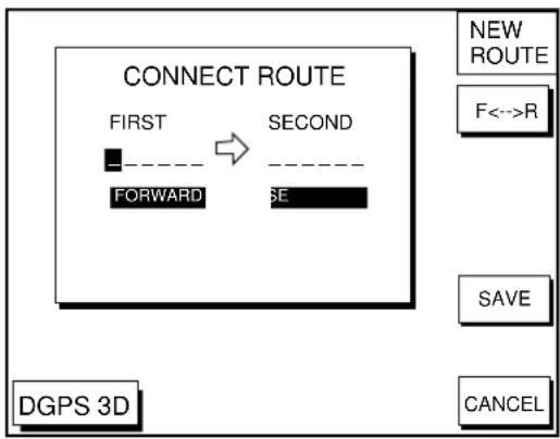
- Press the soft key CONECT ROUTE.
- Enter the registered route name for the first route beneath FIRST in the CONNECT ROUTE window.
flowchart
graph TD
    A["CONNECT ROUTE"] --> B["FIRST"]
    B --> C["FORWARD"]
    B --> D["SECOND"]
    D --> E["SE"]
    F["NEW ROUTE"] --> G["F<->R"]
    H["SAVE"] --> I["CANCEL"]
    J["DGPS 3D"] --> K["End"]
Figure 6-3 Connect route window
- Press the soft key F<-->R to select direction to transverse the waypoints of the route.
- Enter the route name of the second route similar to how you did for the first route.
- Press the soft key SAVE.
Note: The maximum number of waypoints in a route is 35. If this number is exceeded an error message appears. In this case, if desired, delete waypoints in one or both routes so the total number of waypoints does not exceed 35.
6.3 Inserting, Removing Waypoints
Inserting waypoints through the route list
Waypoints can be inserted in routes as follows:
- Press the [WPT/RTE] key followed by the soft key ROUTES to open the route menu.
- Select a route by pressing ▲ or ▼.
- Press the soft key EDIT ROUTE. The route name screen appears.
- Press the soft key LOCAL LIST. All waypoints in the route are displayed.
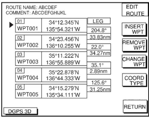
Figure 6-4 Edit route menu
- Press ▲ or ▼ to place the cursor at the location where you want to insert a waypoint.
- Press the soft key INSERT WPT to show the waypoint list.
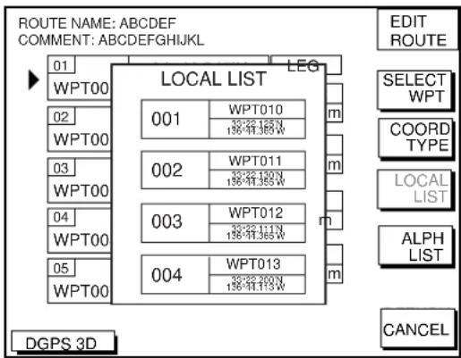
Figure 6-5 Waypoint list for editing a route (Local list)
- Press ▲ or ▼ to select the waypoint you want to insert. You can switch between the local list and alphanumeric list by pressing the soft key LOCAL LIST or ALPH LIST.
- Press the soft key SELECT WPT.
Inserting waypoints on the plotter display
Inserting waypoints before the first waypoint or after the last waypoint
- Press the [WPT/RTE] key followed by the soft key ROUTES to open the route menu.
- Press ▲ or ▼ to select the route desired.
-
Press the soft key EDIT ROUTE.
-
Press the soft key PLOT to show the plotter screen.
- Operate the cursor to place the cursor on the waypoint which you want to insert.
- Press the soft key ADD TO START.
- Operate the cursor pad to place the cursor on an existing waypoint (soft key ADD WPT appears) or new location (soft key ADD NEW WPT appears).
- Press the soft key ADD WPT (ADD NEW WPT).
- Press the [ENTER] key.
When you want to insert waypoints after the last waypoint, press the soft key "ADD TO END" at the step 6.
Inserting waypoints in an intermediate location within a route
- Follow steps 1 through 4 in "Inserting waypoints before the first waypoint or after the last waypoint."
- Operate the cursor pad to place the cursor on a line connecting waypoints.
- Press the soft key SPLIT LEG. The selected line turns red.
- Operate the cursor pad to place the cursor on an existing waypoint (soft key INSERT WPT appears) or new location (soft key INSERT NEW WPT appears). Press the appropriate soft key.
Removing waypoints from routes
Removing route waypoints through the route list
- Press the [WPT/RTE] key followed by the soft key ROUTES to open the route menu.
- Press ▲ or ▼ to select the route desired.
- Press the soft keys EDIT ROUTE and LOCAL LIST to show the waypoint list.
- Press ▲ or ▼ to select the waypoint you want to delete.
- Press the soft key REMOVE WPT.
Removing route waypoints from the plotter display
- Press the [WPT/RTE] key followed by the soft key ROUTES to open the route menu.
- Press ▲ or ▼ to select the route desired.
- Press the soft key EDIT ROUTE.
- Press the soft key PLOT to show the plot screen.
- Operate the cursor pad to place the cursor on the waypoint you want to remove from the route.
- Press the soft key REMOVE WPT.
6.4 Creating Track-based Routes
You can create routes based on your ship's track by entering waypoints at own ship's position. This feature is useful when you wish to retrace a track.
- Press the [WPT/RTE] key to open the waypoint & route menu.
- Press the soft key CREATE VOYAGE BASED ROUTE to show the save route menu.
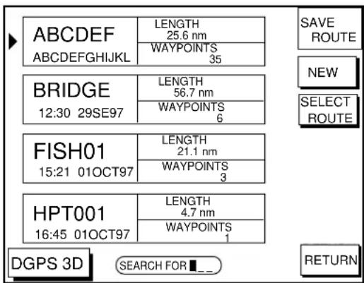
Figure 6-6 Save route menu
- Press the soft key NEW to show the new route window.
flowchart
graph TD
    A["Next consecutive route number"] --> B["ROUTE NAME"]
    B --> C["0 0 6 ____"]
    C --> D["COMMENT"]
    D --> E["----"]
    F["SAVE ROUTE"] --> G["START LOG"]
    H["DGPS 3D"] --> I["CANCEL"]
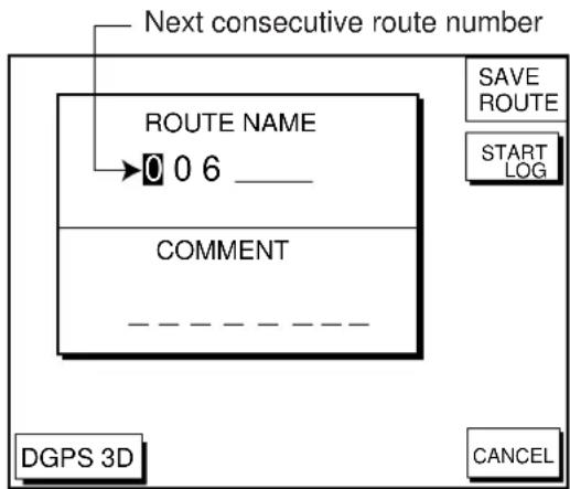
Figure 6-7 New route window
- If required, you may change the route name and enter a comment, using the [CLEAR] key, cursor pad and alphanumeric keys.
- Press the soft key START LOG to show the track-based route screen. If you entered an existing route name at step 4, you are asked if you want to add track-based waypoints to the existing route. Then, press the [ENTER] key to select YES, or the [CLEAR] key to escape.
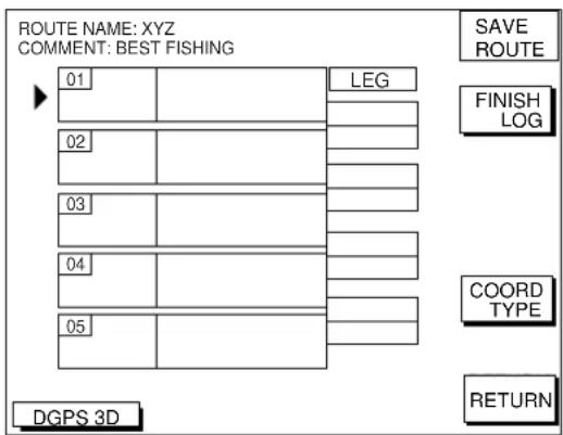
Figure 6-8 Route contents display
- Press the [PLOT] key to show the plot display. The SAVE icon appears at the bottom of the screen.
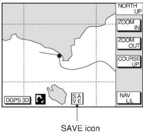
Figure 6-9 SAVE icon appearance on the plotter display
- Press the [SAVE/MOB] key with a touch-and-release action to enter a waypoint mark at own ship position. A new waypoint is created under the next consecutive waypoint number and that waypoint is added to the route.
- Repeat step 7 as necessary. 35 waypoints can be entered.
- Press the [WPT/RTE] key followed by the soft key CREATE VOYAGE BASED ROUTE.
- Press the soft key FINISH LOG to register the route. The SAVE icon disappears.
6.5 Erasing Routes
- Press the [WPT/RTE] key followed by the soft key ROUTES to open the route menu.
- Press ▲ or ▼ to select a route you want to erase.
- Press the soft key ERASE ROUTE. You are asked if you are sure to erase the route.
- Press the [ENTER] key to erase the route.
7.1 Navigating to "Quick Points"
The “quick point” feature allows you to navigate to point(s) without retaining the data indefinitely in your unit’s memory. Each time a quick point is entered the previous quick points having the same quick point numbers are written over.
Selecting quick point entry method
You need to tell your unit how to set the quick point: 1 POINT, 35 POINT (up to 35 points) or WPT/PORT SERV. (For WPT/PORT SERV, see the next page.)
- Press the [MENU] key.
- Press the soft key DISPLAY OPTIONS.
- Select SET GO TO METHOD and press the soft key EDIT. The following display appears.
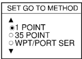
Figure 7-1 Set go to method window
- Select method desired.
- Press the soft key ENTER.
- Press the soft key RETURN to finish.
Navigating to a single quick point
- Select 1 POINT in the "selecting quick point entry method," and return to the plotter display.
-
Place the cursor on an existing waypoint (soft key GO TO WPT appears) or a new location (soft key GO TO CURSOR appears).
-
Depending on the selection you made at step two press the soft key GO TO CURSOR or GO TO WPT.
A light-blue line connects between own ship and destination, marked "QP<01>", and it shows the shortest course to the destination. Arrows on the line show the direction to follow to the quick point. Range and bearing from own ship to the destination appears at the top of screen. This location is saved to the waypoint list as waypoint "QP01."
Navigating to multiple quick points
- Select 35 POINT in the "selecting quick point entry method," and return to the plotter display.
- Press the soft key GO TO.
- Place the cursor on an existing waypoint (soft key SELECT WPT appears) or a new location (soft key ADD QP appears).
-
Depending on the selection you made at step 3 press the soft key SELECT WPT or ADD QP. "QP<01>" appears at the cursor location. To erase last-entered waypoint press the soft key ERASE LST WPT.
-
Repeat steps 3 and 4 to complete.
-
Press the [ENTER] key to register the route.
A light-blue line connects between own ship and all quick points, and it shows the shortest course to destination. Arrows on the line show the direction to follow the route. Quick points are numbered in sequential order from QP<01> and are saved to the waypoint list. Range and bearing from own ship to the first destination appears at the top of screen. The unit saves the points as a route, under the name "Q>RTE" (Quick Route).
7.2 Navigating to Waypoints (waypoint list)
- Press the [WPT/RTE] key to open the waypoint & route menu.
- Press the soft key WAYPOINTS to open the waypoint menu.
- Press the soft key LOCAL LIST or ALPHA/NUMERIC LIST to show corresponding waypoint list.
-
Select a waypoint.
-
Press the soft key GO TO. The plotter display appears. A light-blue line runs between destination selected and own ship's position. Arrows on the line show the direction to the follow. Waypoint data appear at the top of screen.
7.3 Navigating to Ports, Port Services
Some Nav-Charts™ mini chart cards have a port service list which shows services available at ports or harbors. (See page 2-4.) You can use the list to set destination as follows:
- Press the [MENU] key to open the main menu.
- Press the soft key DISPLAY OPTIONS.
- Press ▼ to select SET GO TO METHOD and press the soft key EDIT. The SET GO TO METHOD window appears.
- Press the ▲ or ▼ to select WPT/PORT SER and press the [ENTER] key or the soft key ENTER.
- Press the [PLOT] key to return to the plot-ter display.
- Press the soft key GO TO. Soft key titles change as in Figure 7-2.
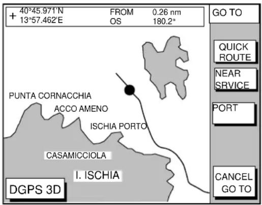
Figure 7-2 Plotter display
- Press the soft key PORT or NEAR SERVICE soft key depending on objective. PORT shows a list of ports in your area. NEAR SERVICE displays the port service list.
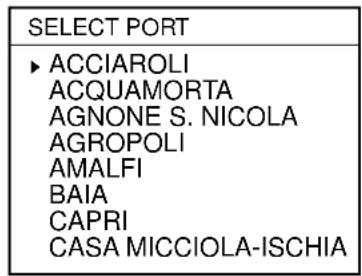
Figure 7-3 Sample port list (southern Italy)
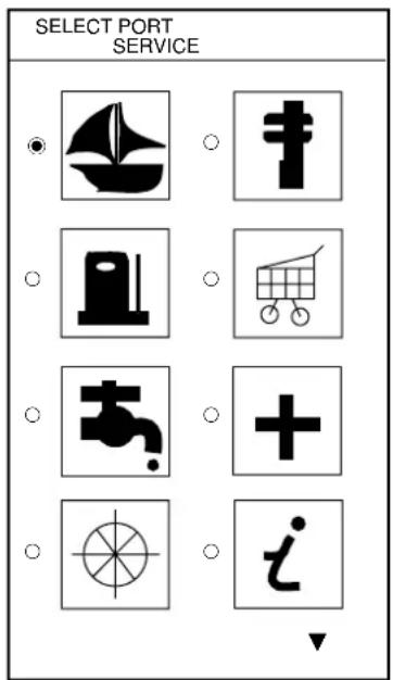
Figure 7-4 Sample port service list
- If you selected PORT in step 7, use the cursor pad to select a port and press the [ENTER] key. Make a route using the soft keys and press the [ENTER] key. (If you want to go directly to that port, simply press the soft key ADD QP followed by the [ENTER] key.)
If you selected NEAR SERVICE in step 7, select service mark desired and then press the soft key ENTER. Then, the display shows the locations of those services nearest you. (Figure 7-5 shows location of filling stations in an area in southern Italy.) Use ▲ or ▼ to place the “hand cursor” on the port service icon desired and press the soft key ENTER. Make a route using the soft keys and press the [ENTER] key. (If you want to go directly to location selected, simply press the soft key ADD QP followed by the [ENTER] key.)
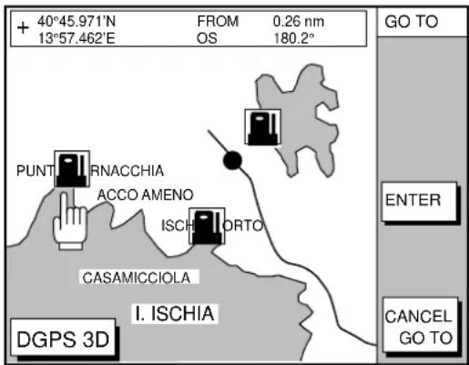
Figure 7-5 Sample filling station locations (southern Italy)
7.4 Following a Route
- Press the [WPT/RTE] key followed by the soft key ROUTE to open the route list.
- Press ▲ or ▼ to select a route.
- Press the soft key GO TO to show the plotter display.
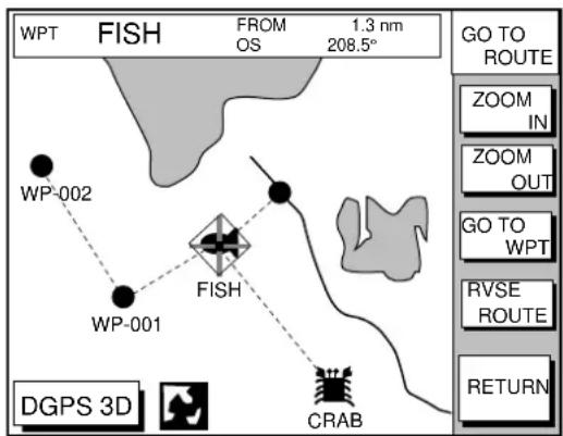
Figure 7-6 Plotter display, route selected as destination
The cursor is on the route waypoint nearest own ship.
- Operate the cursor pad to place the cursor on the waypoint or leg desired in the route.
- Press the soft key GO TO WPT or FOLLOW LEG (depending on the choice at step 4).
Green lines connect all route waypoints and arrows on the lines point in the direction to traverse the route.
Navigate route waypoints in reverse order
Press the soft key RVSE ROUTE to reverse the order to traverse waypoints. The arrows on the route line point in direction selected.
Navigate directly to a route waypoint
If you want to go directly to a route waypoint, place the cursor on the waypoint to show the flashing diamond, and then press the soft key GO TO WPT.
Navigate along specific leg of route
Place the cursor on the leg to display it in a white and red flashing line, and then press the soft key FOLLOW LEG.
Restarting navigation
When you steer to avoid an obstacle or the vessel drifts, you may go off your intended course (Line 1 in Figure 7-7). Use the steering or highway display to return to course.
Also, if you don't need to return to the original course, you can go directly to the waypoint (Line 2 in Figure 7-7) using the restart function as on the next page.
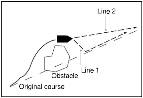
Figure 7-7 Example of when to restart navigation
- Set a destination.
- Press the [WPT/RTE] key to open the waypoint & route menu.
- Press the soft key LOG.
flowchart
graph TD
    A["TO Waypoint (WPT no. in reverse video) Passed waypoint (gray characters)"] --> B["Estimated Time of Arrival at last waypoint"]
    B --> C["ETA 23:59 31.SEP"]
    C --> D["01 BRIDGE 34°23.564'N 135°23.456'E LEG 120.5°"]
    D --> E["02 HARBOR 34°32.456'N 135°32.456'E 23.4nm 23.4nm"]
    E --> F["03 WP<001> 34°23.345'N 135°12.456'E 123.6°"]
    F --> G["04 WP<002> 34°34.555'N 135°55.555'E 23.5nm 180.5°"]
    G --> H["05 WP<003> 34°32.555'N 134°99.999'E 23.5nm 180.5°"]
    H --> I["DGPS 3D"]
    I --> J["LOG RE-START STOP RVSE ROUTE SPEED COORD TYPE"]
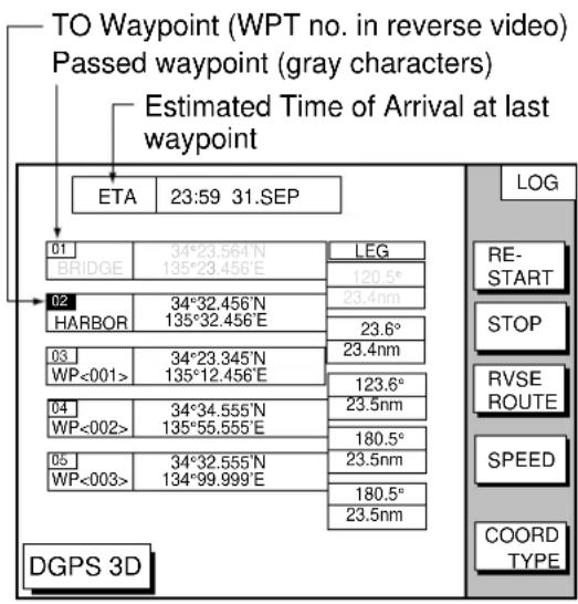
Figure 7-8 Log display
- Press the soft key RESTART.
Setting speed for ETA calculation
Speed, which may be input manually or automatically, is required to calculate ETA (Estimated Time of Arrival) to a waypoint.
- Press the [WPT/RTE] key to display the waypoint & route menu.
- Press the soft key LOG.
- Press the soft key SPEED.
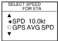
Figure 7-9 Select speed for ETA window
- Key in speed manually in the SPD field, or use GPS speed data by selecting GPS AVG SPD.
- Press the soft key ENTER to register your selection.
Switching waypoints
When you arrive to a waypoint on a route, you can switch to the next waypoint three ways: AUTO1, AUTO2 and MANUAL.
AUTO1: Automatically switches the TO waypoint when your boat is within the arrival alarm area. For how to set the arrival alarm area, see “8.3 Arrival Alarm” on page 8-1.
AUTO2: Automatically switches the TO waypoint when the boat enters the arrival alarm range or the boat passes an imaginary perpendicular line passing through the center of the destination waypoint.
MANUAL: When the boat enters the arrival alarm area, the TO waypoint may be switched by using the soft key RESTART (on the LOG display). If the arrival alarm is not set, the waypoint will not be switched. To be alerted when you arrive at a waypoint turn on the audio alarm. For further details, see "8.2 Audio Alarm On/Off" on page 8-1.
To select waypoint switching method do the following:
- Press the [MENU] key.
- Press the soft key DISPLAY OPTIONS.
- Select WAYPOINTS SW.
- Press the soft key EDIT to show the waypoint sw window.
- Select appropriate waypoint switching method.
- Press the soft key ENTER to close the window.
7.5 Cancelling Navigation
- Press the [WPT/RTE] key.
- Press the soft key LOG.
- Press the soft key STOP.
- Press the [ENTER] key to go stand by.
- Press the soft key RELEASE.
- Press the [ENTER] key.
8.1 Introduction
There are five plotter-related alarms which generate both audible and visual alarms: Arrival alarm, Anchor Watch alarm, XTE (Cross Track Error) alarm, Proximity alarm, and Speed alarm.
When an alarm setting is violated the buzzer sounds, and the speaker icon (☑) appears in red. You may silence the alarm by pressing the [CLEAR] key. The icon remains on the screen until the cause of the alarm is removed or the alarm is deactivated.
8.2 Audio Alarm On/Off
The audio alarm sounds whenever an alarm setting is violated. You can enable or disable the audio alarm as follows:
- Press the [ALARM] key to show the alarm menu.
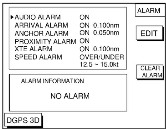
Figure 8-1 Alarm menu
- Press ▲ or ▼ to select AUDIO ALARM.
- Press the soft key EDIT to show the audio alarm window.
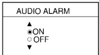
Figure 8-2 Audio alarm window
- Press ▲ or ▼ to select ON or OFF.
- Press the soft key ENTER or the [ENTER] key to register your selection.
8.3 Arrival Alarm
The arrival alarm informs you that your boat is approaching a destination waypoint. The area that defines an arrival zone is that of a circle which you approach from the outside of the circle. The alarm will be released if your boat enters the circle. When the arrival alarm is active a red dashed circle marks the arrival alarm area.
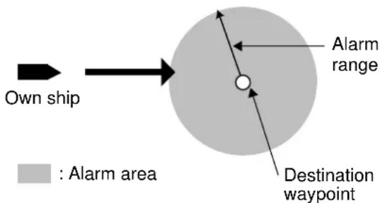
Figure 8-3 How the arrival alarm works
- Press the [ALARM] key to open the alarm menu.
- Press ▲ or ▼ to select ARRIVAL ALARM.
- Press the soft key EDIT to show the arrival alarm window.
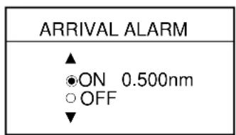
Figure 8-4 Arrival alarm window
- Press ▲ to select ON.
- Operate the cursor pad to place the cursor on the digit desired.
- Key in the alarm range desired. The arrival alarm range is 0.001 to 9.999 miles.
- Press the soft key ENTER or the [ENTER] key.
8.4 Anchor Watch Alarm
The anchor watch alarm informs you that your boat is moving when it should be at rest. When the anchor watch is active, a red dashed circle marks the anchor watch area.
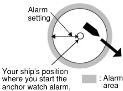
Figure 8-5 How the anchor watch alarm works
- Press the [ALARM] key to open the alarm menu.
- Press ▲ or ▼ to select ANCHOR ALARM.
- Press the soft key EDIT to open the anchor alarm window.
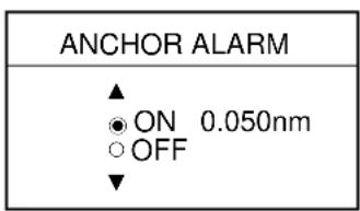
Figure 8-6 Anchor watch alarm window
- Press ▲ to select ON.
- Key in the alarm range desired. The anchor watch range is 0.001 to 9.999 miles.
- Press the soft key ENTER or the [ENTER] key to register your selection.
8.5 XTE (Cross Track Error) Alarm
The XTE alarm warns you when your boat is off its intended course. When the XTE alarm is active two red dashed lines mark the XTE alarm area.
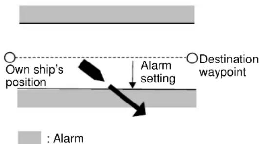
Figure 8-7 How the XTE alarm works
- Press the [ALARM] key to open the alarm menu.
- Press ▲ or ▼ to select XTE ALARM.
- Press the soft key EDIT to open the XTE alarm window.
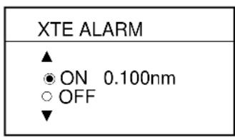
Figure 8-8 XTE alarm window
- Press ▲ or ▼ to select ON.
- Key in the alarm range desired. The XTE alarm range is 0.001 to 9.999 miles.
- Press the soft key ENTER or the [ENTER] key to register your selection.
8.6 Speed Alarm
The speed alarm warns when your boat's speed is within, over/under or under the speed range set.
- Press the [ALARM] key to open the alarm menu.
- Press ▲ or ▼ to select SPEED ALARM.
- Press the soft key EDIT to display the speed alarm window.
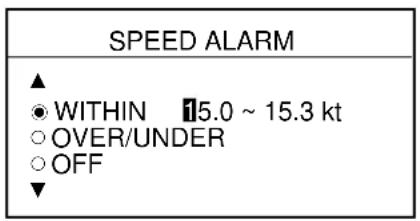
Figure 8-9 Speed alarm window
- Press ▲ or ▼ to select WITHIN, OVER/UNDER, or OFF.
- Key in the alarm range desired.
- Press the soft key ENTER or the [ENTER] key to finish.
8.7 Proximity Alarm
The proximity alarm alerts you when your vessels nears a waypoint by the distance set for that waypoint on the waypoint list. You can globally activate or deactivate the proximity alarm here. Waypoints whose proximity alarm is active have a (○) mark near them.
- Press the [ALARM] key to open the alarm menu.
- Press ▲ or ▼ to select PROXIMITY ALARM.
- Press the soft key EDIT to show the proximity alarm window.
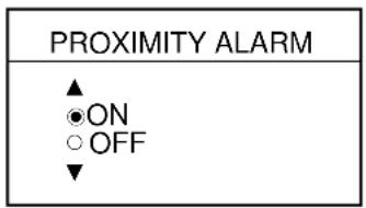
Figure 8-10 Proximity alarm window
- Select ON or OFF by the cursor pad.
- Press the soft key ENTER or the [ENTER] key to register your selection.
8.8 Alarm Information
When an alarm setting has been violated the buzzer sounds and the speaker icon (shown in red) appears. You can see which alarm has been violated, as well as silence the buzzer, on the alarm menu display.
1. Press the [ALARM] key.
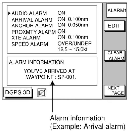
Figure 8-11 Alarm menu
- Press the soft key CLEAR ALARM to silence the buzzer. The color of alarm message and the speaker icon may change from red to black.
Note: The speaker icon is displayed in red until all alarms have been acknowledged on the alarm menu display. If more than one alarm has been violated the message CONTINUE appears at the bottom of the display. In this case press the soft key NEXT INFO to see which other alarms have been violated.
Alarm messages
Table 8-1 Alarm messages and their meanings
| Message | Meaning |
| YOU'VE ARRIVED AT WAYPOINT. | Arrival alarm setting violated. |
| YOU HAVE EXCEEDED ANCHOR WATCH LIMIT. | Anchor watch alarm setting violated. |
| YOU'VE ENTERED AN AVOIDANCE AREA. | Proximity alarm setting violated. |
| YOU HAVE EXCEEDED XTE LIMIT. | XTE alarm setting violated. |
| YOU HAVE EXCEEDED SPEED ALARM LIMIT. | Speed alarm setting violated. |
9. SAVING AND LOADING DATA TO/FROM MEMORY CARD
The following data can be saved to memory card:
- Mark/line
- Waypoints/routes
- Track
- Configuration (menu settings)
9.1 Formatting Memory Cards
Before you can use a memory card it must be formatted. Note that formatting a used card erases all saved data.
- Insert the memory card you want to format into the slot.
- Press the [MENU] key followed by the soft keys CONFIGRATION and UPLOAD/ DOWNLOAD DATA.
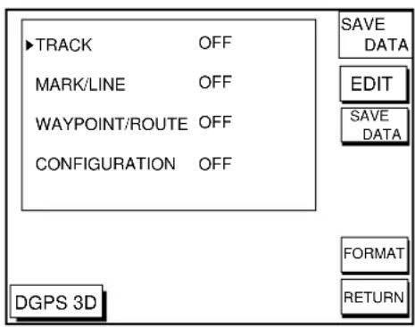
Figure 9-1 SAVE DATA display
- Press the soft key SAVE DATA TO MEMORY CARD and the soft key FORMAT. You are asked if you are ready to format the memory card.
- Press the [ENTER] key to format (or press the [CLEAR] key to escape). Now FOR-MATTING MEMORY CARD appears. Do not remove the card while it is being formatting. When the formatting is completed, FORMAT COMPLETED appears.
- Press the [ENTER] key to finish. Now you can record data to the memory card.
Note: Chart cards cannot be formatted.
9.2 Saving Data to Memory Card
The memory card can save four items of data; track, mark/line, waypoint/route and configuration.
Saving data
- Insert a formatted memory card into the slot.
- Press the [MENU] key followed by the soft keys CONFIGURATION and UPLOAD/ DOWNLOAD DATA.
- Press the soft key labeled SAVE DATA TO MEMORY CARD. The SAVE DATA display (Figure 9-1) appears.
- Press ▲ or ▼ to select item to save.
- Press the soft key EDIT to open the TRACK, MARK/LINE, WAYPOINTS/ ROUTES or CONFIGRATION window.
- Press ▲ to select ON.
- Press the soft key ENTER or the [ENTER] key.
- Repeat from steps 4 to 7 to save other data if desired.
- Press the soft key SAVE DATA. The following message appears and saving starts. Do not remove the memory card while data is being saved.
NOW SAVING DATA TO MEMORY CARD. DO NOT TURN OFF THE POWER UNTIL SAVING COMPLETED.
Figure 9-2 SAVE DATA message
When saving is completed, COMPLETE SAVING DATA appears.
- Press the [ENTER] key.
Error message
Memory card not inserted
Press the [ENTER] key to return to the SAVE DATA display.
MEMORY CARD NOT INSERTED. INSERT CARD PRESS "ENTER" key TO CONTINUE.
Figure 9-3 NOT INSERTED message
Unformatted memory card
Press the [ENTER] key to return to the SAVE DATA display. And format it referring to the previous page.
MEMORY CARD NOT FORMATTED PRESS "ENTER" key TO CONTINUE.
Figure 9-4 NOT FORMATTED message
Wrong card inserted
Appears when a chart card is inserted. Press the [ENTER] key to return to the SAVE DATA display. Replace it with a formatted memory card.
WRONG CARD INSERTED. INSERT MEMORY CARD. PRESS "ENTER" key TO CONTINUE.
Figure 9-5 WRONG CARD message
Data overwrite
Data type to be recorded exists on memory card. (Two or more of same data type cannot be recorded.) Press the [ENTER] key to overwrite same data type on the card, or press the [CLEAR] key to escape.
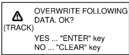
Figure 9-6 OVERWRITE message
9.3 Loading Data from Memory Card
Data (track, marks, waypoints, configuration) can be loaded from a memory card and displayed on the screen. This feature is useful for observing past data and setting up the equipment for a specific purpose (with “configuration”).
- Press the [MENU] key followed by the soft keys CONFIGURATION and UPLOAD/ DOWNLOAD DATA.
- Press the soft key LOAD DATA FROM MEMORY CARD to show the LOAD DATA display.
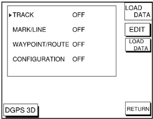
Figure 9-7 LOAD DATA display
- Press ▲ or ▼ to select item to load.
- Press the soft key EDIT to show the ON/OFF selection window.
-
Press ▲ to select ON. Press the soft key ENTER or the [ENTER] key. If the memory card does not contain the item selected, the buzzer sounds and ON cannot be selected.
-
After you select all items desired, press the soft key LOAD DATA to load data. The following message appears.
NOW LOADING DATA FROM MEMORY CARD. DO NOT TURN OFF THE POWER UNTIL LOADING COMPLETE.
Figure 9-8 LOAD DATA message
After loading is completed, the following message appears.
COMPLETE LOADING DATA. PRESS "ENTER" KEY TO CONTINUE.
Figure 9-9 COMPLETE message
- Press the [ENTER] key.
Note on loading data
Track
Since loaded track data is added to internal track, oldest track will be entered when the track memory capacity is exceeded.
Waypoint/route
The loaded data substitutes for previously stored.
Mark/line
The loaded data is added to internal data. When the mark/line memory becomes full no marks may be entered.
Configuration
The loaded data replaces current configuration settings. Press the [ENTER] key to restart. If the memory card is ejected while loading or data could not be loaded, press the [ENTER] key to restart with default settings. Note that track memory capacity is not saved or loaded.
This section describes the various options which allow you to set up your unit to suit your needs.
10.1 CHART SETUP OPTIONS menu
The chart offset options menu provides three menus: chart offset, track control, and chart details.
- Press the [MENU] key to open the main menu.
- Press the soft key CHART SETUP OPTIONS.
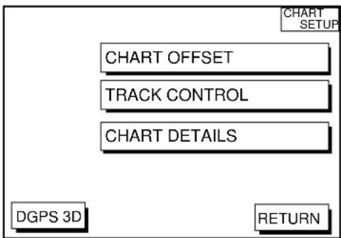
Figure 10-1 Chart setup options menu
CHART OFFSET menu
In some instances position may be off by a few minutes. For example, the position of the ship is shown to be at sea while it is in fact moored at a pier. You can compensate for this error by offsetting chart position as follows:
- Press the [MENU] key followed by the soft keys CHART SETUP OPTIONS and CHART OFFSET.
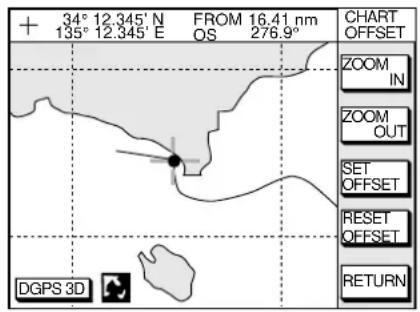
Figure 10-2 Plotter display, chart offset selected
- Use the cursor pad to place the cursor where to offset chart position.
- Press the soft key SET OFFSET.
- Press the soft key RETURN to finish.
To cancel chart offset, press the soft key RESET OFFSET at step 3 in the above procedure.
TRACK CONTROL menu
This menu mainly controls track color and track plotting interval. For further details see Chapter 3.
CHART DETAILS menu
- Press the [MENU] key followed by the soft keys CHART SETUP OPTIONS and CHART DETAILS.
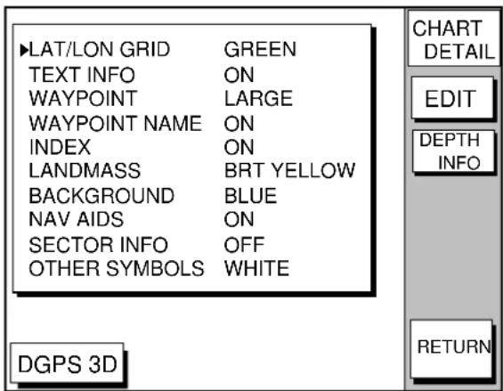
Figure 10-3 Chart details menu
- Use the cursor pad to select item and press the soft key EDIT.
- Select option with cursor pad and press the soft key RETURN to finish.
Chart details menu description
LAT/LONG GRID: Turns lat/long grid on/off and changes its color. The default settings are ON and green.
TEXT INFO: Turns geographic name display on/off. The default setting is ON.
WAYPOINT: Turns waypoint on or off and selects size to large or small. "LARGE" displays waypoint in shape selected; "SMALL" shows waypoints as an X regardless of actual shape. "OFF" only display waypoints when they are used in navigation. The default setting is LARGE.
WAYPOINT NAME: Turns waypoint name on/off. The default setting is ON.
INDEX: Turns chart indices on/off. The default setting is ON.
LANDMASS: Selects brightness and color of landmass. The default settings are bright and yellow.
BACKGROUND: Select background color to black or blue (default setting).
NAV AIDS: Turns aids to navigation symbols (for example, buoys) on/off. The default setting is ON. When OFF is selected, symbols are displayed and information is not.
SECTOR INFO: Turns lighthouse viewable angle indication on FURUNO charts on/off. Viewing angle is shown as an arc extending from lighthouse position. Arc color, white or green, is the color of the light beam. This feature is available with selected charts. The default setting is ON.
OTHER SYMBOLS: Selects color of all other chart symbols. The default setting is white.
DEPTH INFO soft key: Turns depth info display on/off and sets it color.
10.2 DISPLAY OPTIONS menu
This menu contains items for setting up the plotter display.
- Press the [MENU] key.
- Press the soft key DISPLAY OPTIONS. The display setup1 menu appears.
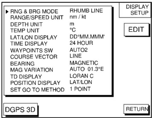
Figure 10-4 Display setup menu
Display setup menu description
RNG & BRG MODE
The GPS receiver calculates the range, bearing, cross track error (XTE) and ETA to TO waypoint when you set a destination. The range and bearing can be calculated by GREAT CIRCLE (straight line between two points) or RHUMB LINE (straight line between two points on nautical chart, default setting) method.
RANGE/SPEED UNIT
Selects the unit for range and speed; nm/kt (default setting), km/ km/h, sm/ sm/h.
DEPTH UNIT
Selects unit of depth measurement among, feet, fathoms, and meters. The default setting is feet.
TEMP UNIT
Selects unit of water temperature measurement between Celsius or Fahrenheit. The default setting is Fahrenheit.
LAT/LON DISPLAY
Displays the seconds of latitude and longitude positions in hundredths, thousandths (default setting) or ten thousandths.
TIME DISPLAY
Selects time display format for 12 hour or 24 hour (default setting).
WAYPOINT SW
Provides automatic or manual waypoint switching when following a route. For further details, see page 7-4. The default setting is AUTO2.
COURSE VECTOR
You may extend a line from the own ship position to show ship's course. The line can be a vector (the length depends on the ship's speed.) or a line (course bar). The default setting is LINE.
BEARING
A navigation device outputs both true and magnetic bearings. A magnetic bearing is true bearing plus (or minus) earth's magnetic deviation. Thus the equation for finding magnetic bearing is;
true bearing ± x (magnetic variation) ^ = magnetic bearing
You can display your ship's course and bearing to waypoint in true or magnetic bearing, and the default setting is magnetic.
MAG VARIATION
The magnetic variations for all areas of the earth are preprogrammed into this unit. The preprogrammed variation is accurate for most instances, however you may wish to manually enter a variation.
- Select MAG VARIATION, and press the soft key EDIT to show the mag variation window.
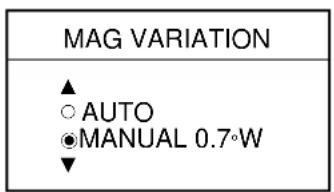
Figure 10-5 Mag variation window
- Select MANUAL.
- Key in magnetic deviation value.
- Press the soft key W<-->E to switch between East and West and vice versa, if necessary.
- Press the soft key ENTER or the [ENTER] key to finish.
TD DISPLAY
Position may be shown in Loran C TDs (default setting), Decca TDs, or latitude and longitude. To display position in TDs select Loran C or Decca here and choose TD at "POSITION DISPLAY" below. You can select the Loran C or Decca chain to use on the TD SETUP menu. For details see "TD SETUP menu" on page 10-6.
POSITION DISPLAY
Displays position in latitude and longitude (default setting) or Loran C or Decca TDs.
SET GO TO METHOD
Selects the method for entering the quick point: 1 POINT (default setting), 35 POINT (2-35 points), or WPT/PORT SER. For further details see pages 7-1 and 7-2.
OPERATION MODE
Selects the operation mode between PLEASURE and FISHING. For further details see page 2-8.
10.3 GPS/DGPS/TD OPTIONS menu
This menu sets up GPS and DPGS receivers and enables display of position in Loran C or Decca TDs.
- Press the [MENU] key.
- Press the soft key GPS/DGPS/TD OPTIONS to display the GPS/DGPS/TD options menu.
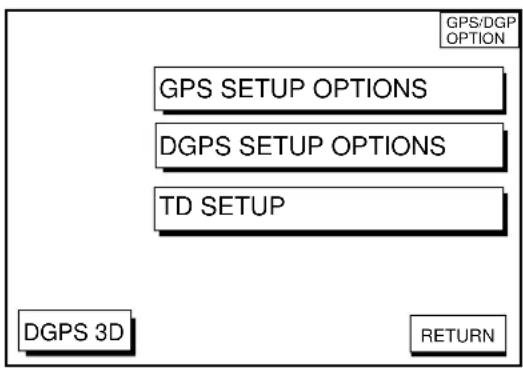
flowchart
graph TD
    A["GPS/DGP OPTION"] --> B["GPS SETUP OPTIONS"]
    B --> C["DGPS SETUP OPTIONS"]
    C --> D["TD SETUP"]
    D --> E["DGPS 3D"]
    E --> F["RETURN"]
Figure 10-6 GPS/DGPS/TD options menu
GPS SETUP OPTIONS menu description
This menu provides items for setting up the GPS receiver. To display it, show the menu shown in Figure 10-6, and then press the soft key GPS SETUP OPTIONS.
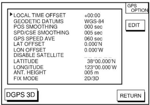
Figure 10-7 GPS SETUP options menu
LOCAL TIME OFFSET
GPS uses UTC time. If you would rather use local time, enter the time difference between local time and UTC time. Use the soft key +<-->- to switch from plus to minus and vice versa.
GEODETIC DATUM
The GP-1850D, GP-1850 is preprogrammed with most of the major chart systems of the world. Although the WGS-84 system, the GPS standard, is now widely used other categories of charts still exist. Select the chart system used, not the area where your boat is sailing. The default chart system is WGS-84.
- Select GEODETIC DATUMS.
- Press the soft key EDIT to show the geodetic datum window.
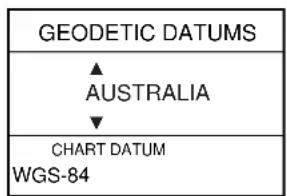
Figure 10-8 Geodetic datum window
- Press ▲ or ▼ to select the chart system you are using. If no chart datum exists for geodetic datum selected UNKNOWN appears in the CHART DATUM window. In this case select a different chart system.
- Press the soft key ENTER or the [ENTER] key to register your selection.
POS SMOOTHING
When the DOP or receiving condition is unfavorable, the GPS fix may change greatly, even if the vessel is dead in water. This change can be reduced by smoothing the raw GPS fixes. A setting between 000 to 999 is available. The higher setting the more smoothed the raw data, however too high a setting shows response time to change in latitude and longitude. This is especially noticeable at high ship's speeds. 000 is the normal setting; increase the setting if the GPS fix changes greatly.
SPD/CSE SMOOTHING
During position fixing, ship's velocity (speed and course) is directly measured by receiving GPS satellite signals. The raw velocity data may change randomly depending on receiving conditions and other factors. You can reduce this random variation by increasing the smoothing. Like with latitude and longitude smoothing, the higher the speed and course smoothing the more smoothed the raw data. If the setting is too high, however, the response to speed and course change slows. For no smoothing, enter all zeroes. The default setting is 5 (sec).
GPS SPEED AVE
Calculation of ETA is based on average ship's speed over a given period. If the period is too long or too short calculation error will result. Change this setting if calculation error occurs. The default setting is 60 seconds, which is suitable for most conditions.
LAT OFFSET, LON OFFSET
GPS generated position may be off by some seconds due to GPS signal variation. You may apply an offset to GPS position to refine position accuracy.
DISABLE SATELLITE
Every GPS satellite is broadcasting abnormal satellite number(s) in it's Almanac, which contains general orbital data about all GPS satellites, including those which are malfunctioning. Using this information, the GPS receiver automatically eliminates any malfunctioning satellite from the GPS satellite schedule. However, the Almanac sometimes may not contain this information. If you hear about a malfunctioning satellite from another source, you can disable it manually. Enter satellite number (max. 3 satellites) in two digits and press the soft key ENTER or the [ENTER] key.
LATITUDE, LONGITUDE
The default latitude and longitude position is San Francisco, USA (38.00.00'N, 123.00.000'W). When the unit is turned on first the first time it begins searching for its actual position. To lessen the time required to find position, you may enter your position manually. To switch from North to South and vice versa, use the soft key N<-->S, and to switch from West to East and vice versa, use the soft key W<-->E. Finally, press the soft key ENTER or the [ENTER] key.
ANT. HEIGHT
Enter the height of the antenna unit above sea surface. For further details refer to the installation manual. The default setting is 5 m.
FIX MODE
You can choose the position-fixing mode from 2D or 2D/3D. 2D requires three satellites to fix position; 2D/3D requires three or four satellites, whichever is available. The default setting is 2D/3D.
DGPS SETUP OPTIONS menu
This menu sets parameters for the DGPS beacon receiver. (GP-1850D, or GP-1850 equipped with DGPS beacon receiver.) To display it, press the [MENU] key followed by the soft keys GPS/DPGS/TD OPTIONS and DGPS SETUP OPTIONS.
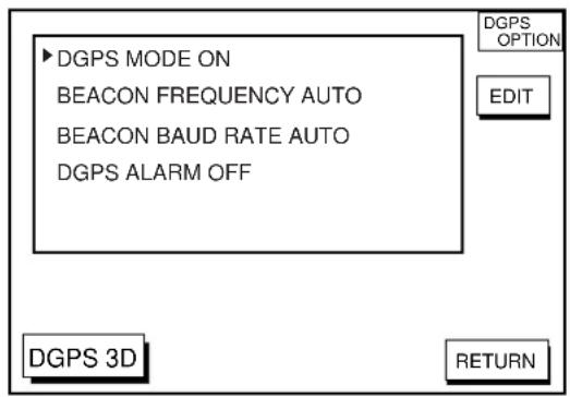
Figure 10-9 DGPS setup options menu
DGPS MODE
Select ON to use the DGPS mode. The default setting is ON. A DGPS beacon receiver must be connected to use this mode.
BEACON FREQUENCY
DGPS reference station can be searched automatically or manually. For manual search, select MANUAL here, and use the cursor pad to select frequency of DGPS reference station. The default setting is AUTO.
BEACON BAUD RATE
Selects the transmission rate of the DGPS reference station nearest you, among AUTO (default setting), 50, 100 or 200 bps. This setting is only effective when the DGPS mode is “manual”; baud rate cannot be changed in automatic DGPS mode.
DGPS ALARM
Enable/disable the DGPS alarm. When enabled, the audio alarm sounds three times if position cannot be found with DGPS. The default setting is ON.
TD SETUP menu
This menu selects the Loran C or Decca chain to use to display position in TDs. To display it, press the [MENU] key followed by the soft keys GPS/DPGS/TD OPTIONS and TD SETUP.
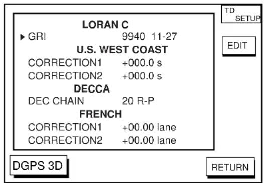
Figure10-10 TD setup menu
Displaying LORAN C TDs
- Select GRI and press the soft key EDIT to show the GRI & sta. pair window.
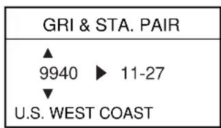
Figure 10-11 GRI & sta. pair window
- Press ▲ or ▼ to select GRI code. Press ▶ to enable selection of station pair, and then press ▲ or ▼ to select station pair. See the Loran C chain list at the end of this manual for GRI and station pairs.
- Press the soft key ENTER or the [ENTER] key to register your selection.
- If necessary, you may enter a position offset to refine Loran C position. Select LO-RAN C CORRECTION1 or CORRECTION2 and press the soft key EDIT. Enter correction value and press the soft key ENTER or the [ENTER] key. Use the soft key + <--> - to switch from plus to minus and vice versa.
Displaying DECCA TDs
- Select DEC CHAIN and press the soft key EDIT to show the chain sta. pair window.
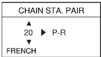
Figure 10-12 Chain sta. pair window
- Press ▲ or ▼ to select Decca chain number. Press ▶ to enable selection of lane, and then press ▲ or ▼ to select lane pair (R: red, G: green and P: purple). Refer to the Decca chain list at the end of this manual.
- Press the soft key ENTER or the [ENTER] key to register your selection.
- If necessary, you may enter position offset to refine Decca position. Select DECCA CORRECTION1 or CORRECTION2 and press the soft key EDIT. Enter correction value and press the soft key ENTER or the [ENTER] key. Use the soft key + <--> - to switch from plus to minus and vice versa.
10.4 CONFIGURATION menu
The configuration menu has facilities for setting up data ports, uploading/downloading data, self test, demonstration mode setup, and memory clearing.
- Press the [MENU] key.
- Press the soft key CONFIGURATION to display the configuration menu.
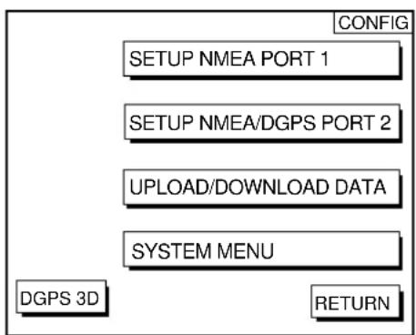
Figure 10-13 Configuration menu
SETUP NMEA PORT 1 menu description
This menu sets up DATA PORT 1 according to the specifications of the equipment connected to it. The menu can be displayed by pressing the [MENU] key followed by the soft keys CONFIGURATION and SETUP NMEA PORT 1. For detailed information, see the installation manual.
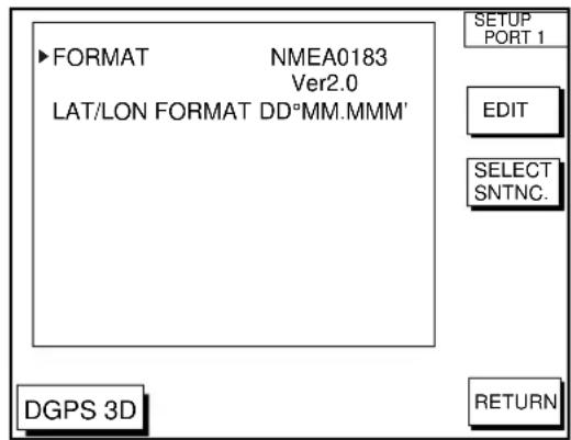
Figure 10-14 Setup NMEA port 1 (or 2) menu
FORMAT
Selects NMEA0183 version 1.5 or 2.0. If you are unsure of the version of external equipment try both and choose the one which outputs data correctly. The default setting is version 2.0.
LAT/LON FORMAT (GGA only)
Selects the seconds of latitude and longitude positions in hundredths, thousandths or ten thousandths.
Soft key SELECT SNTNC
This key enables/disables input/output of data sentences.
SETUP NMEA/DGPS PORT 2 menu description
This menu should be set according to the specifications of the equipment connected to connectors PORT 1 (NMEA) and PORT 2 (DGPS) at the rear of the display unit. The menu can be displayed by pressing the [MENU] key followed by the soft keys CONFIGURATION and SETUP NMEA PORT 2. For detailed information, see the installation manual.
FORMAT
Selects data format of connected equipment; NMEA0183 version 1.5, version 2.0, RTVM104 (EXTRN), RTCM104 (INTRN) or RTCM104 (OUTPUT). RTCM104 (INTRN) is for GP-1850D only. The default setting is RTVM104 (EXTRN).
The procedure for setting LAT/LON FORMAT are similar to those for PORT 1. Note that you cannot setup data sentences when you select RTCM104 (INTRN) as the format. (A level converter (IF-1432) is required when using NMEA0183 format.)
LAT/LON FORMAT (GGA only)
Selects the seconds of latitude and longitude positions in hundredths, thousandths or ten thousandths.
UPLOAD/DOWNLOAD DATA menu
This menu allows you to upload waypoint and route data to a PC or download the same data from a PC, via the DGPS connector at the back of display unit. The menu can be displayed by pressing the [MENU] key followed by the soft keys CONFIGURATION and UPLOAD/DOWNLOAD DATA. For detailed information, see the installation manual.
For memory card, see chapter 9.
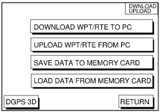
flowchart
graph TD
    A["DOWNLOAD WPT/RTE TO PC"] --> B["UPLOAD WPT/RTE FROM PC"]
    B --> C["SAVE DATA TO MEMORY CARD"]
    C --> D["LOAD DATA FROM MEMORY CARD"]
    D --> E["DGPS 3D"]
    E --> F["RETURN"]
    G["DOWNLOAD UPLOAD"] --> A
Figure 10-15 Upload/download menu
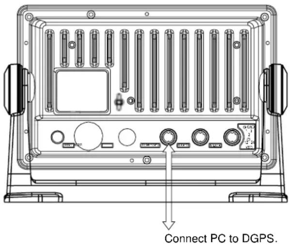
Figure 10-16 Display unit, rear view
Set communication software on the PC as follows:
Baud Rate: 4800 bps
Character Length: 8 bit
Stop bit: 1 bit
Parity: None
X Control: XON/XOFF
The following data can be downloaded/uploaded between a personal computer and this equipment.
- Waypoint data (In alphanumeric order)
- Route data (In order of route number)
- End of sentence
Note 1: There are two kinds of data for route data: route data and route comment data.
Note 2: DGPS position fix is not available when uploading or downloading data.
Download waypoint/route to PC
- Connect the PC to the equipment as shown below.
- Press the soft key labeled DOWNLOAD WPT/RTE TO PC. You are asked if you are ready to download waypoints and routes.
- Press the [ENTER] key to download.
Upload waypoint/route from PC
Note that all waypoint and route data stored in your unit will be deleted when data is uploaded.
- Connect the PC to the equipment as shown below.
- Press the soft key labeled UPLOAD WPT/RTE FROM PC. You are asked if you are ready to upload waypoints and routes.
- Press the [ENTER] key to upload.
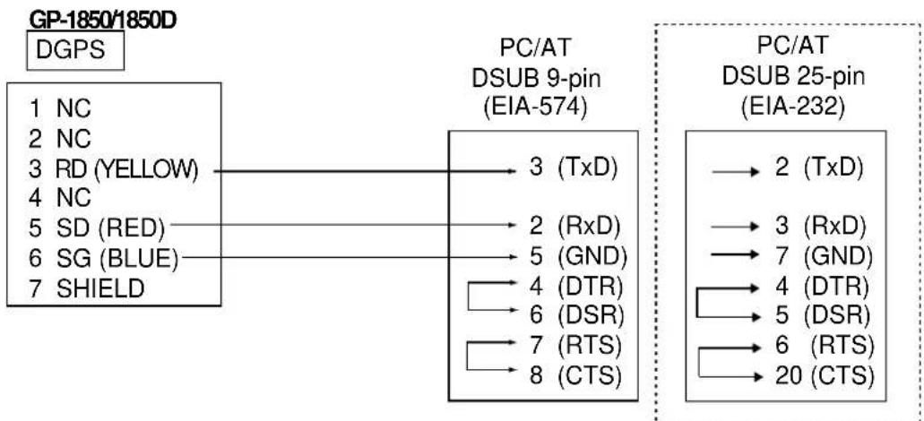
flowchart
graph LR
    A["GP-1850/1850D"] --> B["DGPS"]
    B --> C["1 NC"]
    B --> D["2 NC"]
    B --> E["3 RD (YELLOW)"]
    B --> F["4 NC"]
    B --> G["5 SD (RED)"]
    B --> H["6 SG (BLUE)"]
    B --> I["7 SHIELD"]

    C --> J["PC/AT DSUB 9-pin (EIA-574)"]
    D --> J
    E --> J
    F --> J
    G --> J
    H --> J
    I --> J

    J --> K["3 (TxD)"]
    J --> L["2 (RxD)"]
    J --> M["5 (GND)"]
    J --> N["4 (DTR)"]
    J --> O["6 (DSR)"]
    J --> P["7 (RTS)"]
    J --> Q["8 (CTS)"]

    K --> R["PC/AT DSUB 25-pin (EIA-232)"]
    L --> R
    M --> R
    N --> R
    O --> R
    P --> R
    Q --> R

    R --> S["2 (TxD)"]
    R --> T["3 (RxD)"]
    R --> U["7 (GND)"]
    R --> V["4 (DTR)"]
    R --> W["5 (DSR)"]
    R --> X["6 (RTS)"]
    R --> Y["20 (CTS)"]
Figure 10-17 Connection of GP-1850D/GP-1850 to PC
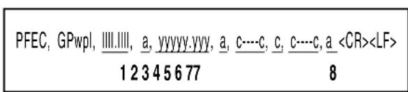
Figure 10-18 Waypoint data format
1: Waypoint latitude
2: N/S
3: Waypoint longitude
4: E/W
5: Waypoint name (Number of characters is fixed to 6 and space code is placed when the number of characters are less than 6.)
6: Waypoint color
7: Waypoint comment (1 byte for mark code + 13 characters of comment.)
1st byte of mark code: Fixed to '@'.
2nd byte of mark code: Internal mark code. See Note 1.
8. Information of marking waypoint. Always set to "A".
"A": Displayed
"V": Not displayed
Note 1: Following characters can be used for comments:
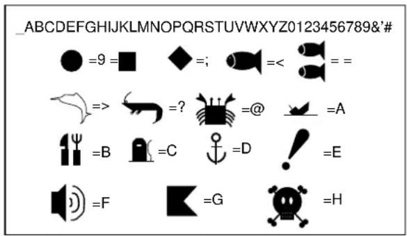
Figure 10-19 Character available for comment
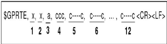
Figure 10-20 route data format
1: Number of sentences required for one complete route data (1 to 4). See Note 2.
2: Number of sentences currently used (1 to 4)
3: Message mode (Always set to C)
4: Route No. (001 to 300, 3 digits required)
5 through 12: Waypoint name (Max. 8 names, length of each waypoint name is fixed to 7 byte)
Note 2: A route can may contain 35 waypoints and GPRTE sentence for one route data may exceed 80 byte limitation. In this case, route data is divided into several GPRTE sentences (Max. 4 sentences). This value shows the number of sentences the route data has been divided.
Route comment data format
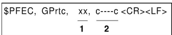
Figure 10-21 Route comment format
1: Route No. (01 to 200, 3 digits required)
2: Route comment (Max. 16 characters, variable length)
The same characters of the comment for waypoint comment can be used.
End of sentence
\$PFEC, GPxfr, CTL, E
Figure 10-22 End of sentence
SYSTEM menu
This menu provides testing facilities, demonstration mode setup and memory/trip clear. You may display it by pressing the [MENU] key followed by the soft keys CONFIGURATION and SYSTEM MENU.
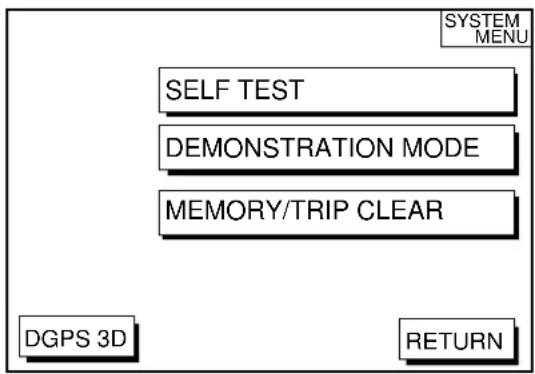
flowchart
graph TD
    A["SELF TEST"] --> B["DEMONSTRATION MODE"]
    B --> C["MEMORY/TRIP CLEAR"]
    C --> D["DGPS 3D"]
    D --> E["RETURN"]
Figure 10-23 System menu
SYSTEM MENU description
SELF TEST, MEMORY/TRIP CLEAR: SELF TEST and MEMORY/TRIP CLEAR are described in Chapter11.
DEMONSTRATION MODE: This sets the parameters for the demonstration display. For further details see page 1-6.
The GP-1850D/1850 C-MAP NT series uses FURUNO mini chart card and C-MAP NT-FP chart card. These charts show accurate coastlines, depth contours, place names, aids to navigation such as buoys and lighthouses, and other navigational marks.
11.1 Inserting Chart Card
Insert an appropriate chart card before turning on the power.
- Push down the lid catch to open the chart card slot cover.
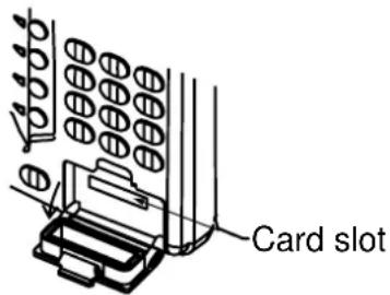
Figure 11-1 Location of chart card slot cover
- Insert appropriate chart card groove side up.
- Close the slot cover to protect the chart drive. (Keep the slot cover closed at all times.)
Note1: Turn off the power before inserting or ejecting the chart card.
Note2: When using C-MAP NT-FP card, do not eject it while a chart is being drawn. This may cause the equipment to stop working.
11.2 Cursor and Data Display
Besides its fundamental functions of providing position data, the cursor can also show caution area, depth area, source of data, etc. Further, you can display information about an icon by placing the cursor on it.
- Press the cursor pad to turn the cursor on.
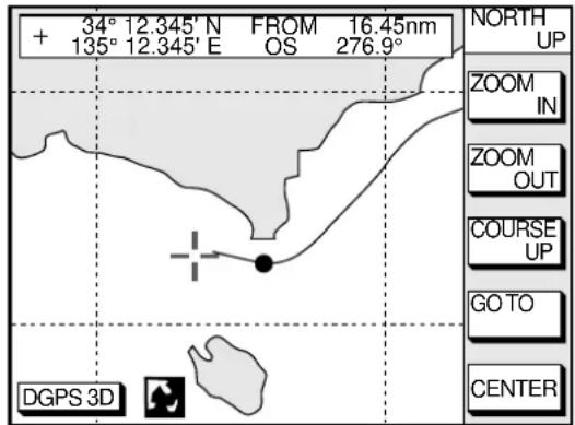
Figure 11-2 Plotter display
- Use the cursor pad to place the cursor on the position desired.
- Press the [ENTER] key to open the Objects window. For example the following window appears.
Objects
Caution area
Depth area
Source of data
Figure 11-3 Objects window
- Press ▲ or ▼ to select the item desired.
- Press the soft key ENTER or the [ENTER] key to display details for object selected Objects.
Caution area
Information
LEUCHTFEUER DIE KARTE ENTHAEL T NUR DIE LAGEN DER WICHTIGEN FEUER. LIGHTS ONLY THE PRINC IPAL LIGHTS ARE SHOWN ON THIS CHART. MISSWEISUNG SIEHE K ARTEN GROESSEREN MASSSTABS. MAGNETIC VARIATION LOCAL MAGNETIC ANOMALIES SEE LARGER SCALE CHARTS.
Figure 11-4 Example of caution area window
- Press the soft key CANCEL to close the window.
- Repeat step 4 to 6 to select other item.
- Press the soft key CANCEL to close the Objects window.
When you place the cursor on any icon, its information appears.
- Place the cursor on a lighthouse icon.
Place the cursor on a lighthouse icon.
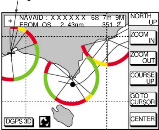
Figure 11-5 Lighthouse icon
- Press the [ENTER] key. For example, the following window appears.
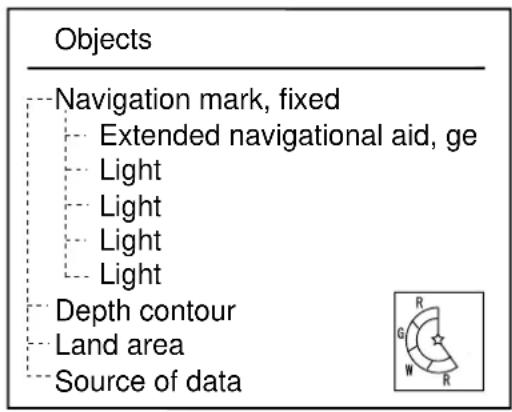
Figure 11-6 Object windows
- Press ▲ or ▼ to select the item desired.
- Press the [ENTER] key to display detailed information.
Navigation mark, fixed Light.
Color white
Height 7.00 Meters
Light characteristic occulting XXXXXXXXX XXXXXXXXX
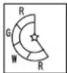
Figure 11-7 Sample lighthouse data
- Press the soft key CANCEL to close the Objects window.
11.3 Tidal Information
The C-MAP NT-FP chart card provides for calculation of the tide heights for any date. Additionally it displays the times of sunrise and sunset.
- Press the cursor pad to place the cursor on a Tide icon.

Figure 11-8 Tide icon
- Press the [ENTER] key to open the Objects window.
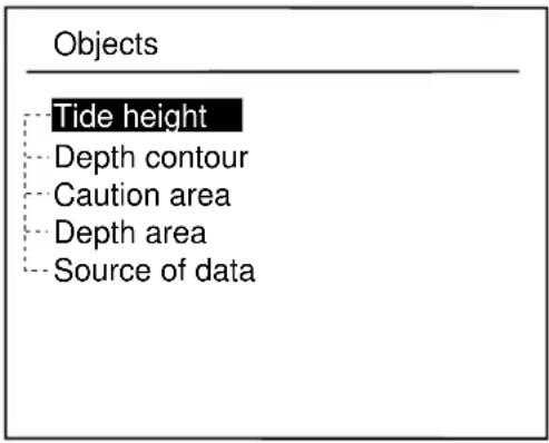
Figure 11-9 Objects window
- Press ▲ or ▼ to select Tide height.
- Press the soft key ENTER or the [ENTER] key to open the TIDE window.
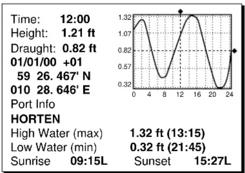
line
| Time | Height | Draught | Port Info | | -------- | -------- | -------- | --------- | | 12:00 | 1.21 ft | 0.82 ft | | | 01/01/00 | +01 | | | | 59 | 26.467' N| | | | 010 | 28.646' E| | | | 24 | | | | | High Water (max) | | | 1.32 ft (13:15) | | Low Water (min) | | | 0.32 ft (21:45) | | Sunrise | 09:15L | | Sunset | | 15:27L | | | |Figure 11-10 TIDE window
- Press the soft key DATE to open the DATE window.
| DATE |
| DD/MM/YYYY 01 / 01 / 2000 |
Figure 11-11 DATE window
-
Use ◀ or ▶ to position the cursor where desired and then press the appropriate numeric keys to enter a date.
-
Press the soft key ENTER or the [ENTER] key to show the tidal graph for entered date.
- Press ◀ or ▶ to locate the vertical cursor on the time desired. Time and height are shown to the left of the graph.
- Press ▲ or ▼ to shift the level cursor. Draught is shown to the left of the graph.
- Press the soft key CANCEL to close the TIDE window.
11.4 Navigating to Ports, Port Services
The C-MAP NT-FP chart provides detailed information on aids to navigation (buoy, lighthouse) and port service information that you specify with the cursor. The port service information includes the availability of water and fuel supplies, shipyards and first aid, etc. You can use the list to set destination as follows:
- Press the [MENU] key to open the main menu.
- Press the soft key DISPLAY OPTIONS.
- Press ▼ to select SET GO TO METHOD and press the soft key EDIT. The SET GO TO METHOD window appears.
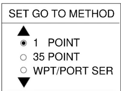
Figure 11-12 SET GO TO METHOD window
- Press ▼ to select WPT/PORT SER and press the soft key ENTER or the [ENTER] key.
-
Press the [PLOT] key once or twice to return the plotter display.
-
Press the soft key GO TO. Soft key titles change as in Figure 11-10. If GO TO key is not displayed, press the cursor pad.
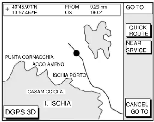
Figure 11-13 Plotter display
- Press the soft key NEAR SERVICE. The SELECT PORT SERVICE window appears.
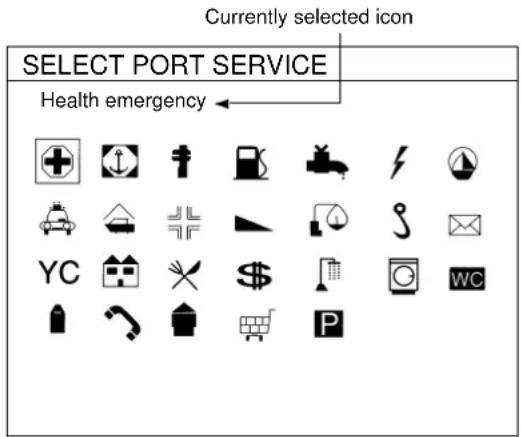
Figure 11-14 SELECT PORT SERVICE window
- Use the cursor pad to select service mark desired. Currently selected icon is circumscribed. The name of currently selected icon appears at the top of the window. Refer to the user's manual of C-MAP NT for details about the icons.
- Press the soft key ENTER or the [ENTER] key. Then, the display shows the locations of those services nearest you.
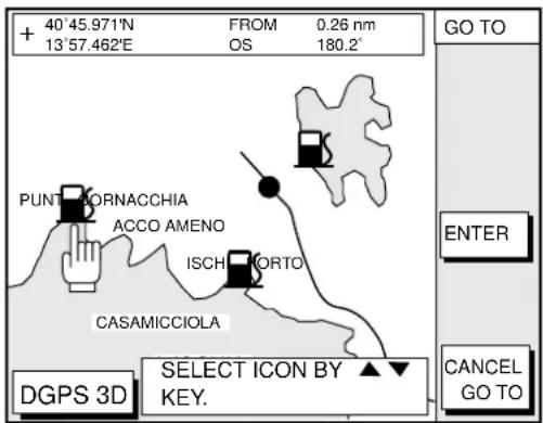
Figure 11-15 Sample filling station locations
- Press ▲ or ▼ to place the "hand cursor" on the port service icon desired and press the soft key ENTER or the [ENTER] key.
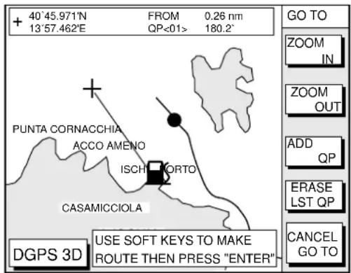
Figure 11-16 Make route window
- Do one of the following: Go directly to port service selected: Press the [ENTER] key. The own ship and the port service is connected by a blue line. The range and bearing form own ship to the port service appears at the navigation data display. You can go to the port service directly by steerings the ship to the hearing indicated.
Go to port service selected via waypoints, make a route as follows:
a) Move the cursor to the nearest waypoint of the port service.
b) Press the soft key ADD QP.
c) Repeat the above steps a) and b) to enter other waypoints.
d) Press the [ENTER] key to finish.
A line connects between own ship and the port service. And the range and bearing from own ship to first waypoint appears.
Note: Destination is automatically cancelled if there is no port for service selected.
11.5 Setting Chart Setup Options
CHART DETAILS menu
- Press the [MENU] key followed by the soft keys CHART SETUP OPTIONS and CHART DETAILS.
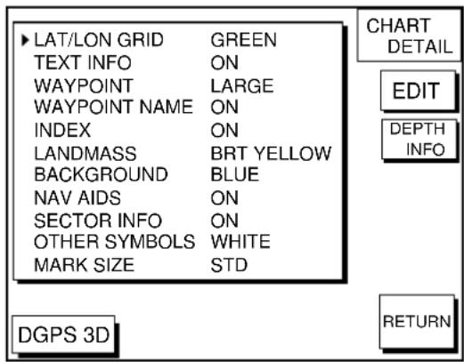
Figure 11-17 Chart details menu
- Press ▲ or ▼ to select item and press the soft key EDIT.
- Select option with cursor pad and press the soft key ENTER or the [ENTER] key.
- Press the soft key RETURN to finish.
Items which are concerned with C-MAP NT-FP chart card are described here.
LANDMASS: Selects brightness and color of land. The default settings are bright (BRT) and yellow. When you select OFF, color of land is black.
BACKGROUND: When the C-MAP NT-FP chart card is used, this function is no inoperative.
NAV AIDS: Turns aids to navigation symbols (for example, buoys) on/off. The default setting is ON. When OFF is selected, symbols are displayed but information is not displayed (at the upper part of the screen).
SECTOR INFO: Turns lighthouse viewable angle indication on C-MAP NT-FP chart on/off. Viewing angle is shown as an arc extending from lighthouse position. This feature is available with selected charts. The default setting is ON. When you select OFF, the visual information is not displayed and the lighthouse is displayed as “!”.
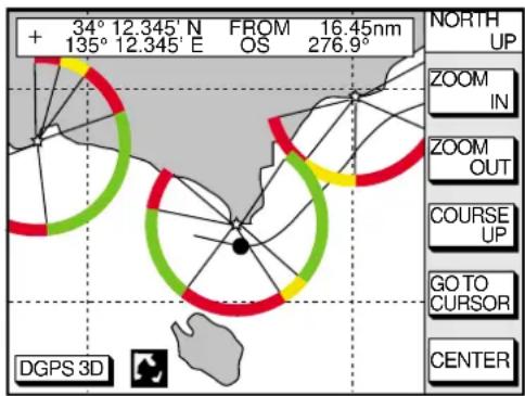
Figure 11-18 SECTOR INFO
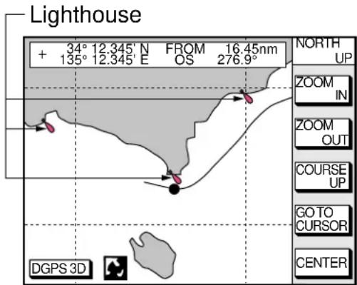
Figure 11-19 Lighthouse appearance when SECTOR INFO is off
OTHER SYMBOLS: Selects color of all other chart symbols. The default setting is white. When you select OFF, navaid icons are not displayed but alarm icons are displayed.
DEPTH INFO soft key: Turns the DEPTH INFO display on/off and sets it color in FURUNO chart, or selects the depth areas limit and spot sounding & bathymetric range in C-MAP NT-FP chart.
- While displaying chart details menu, press the soft key DEPTH INFO to show the following display.
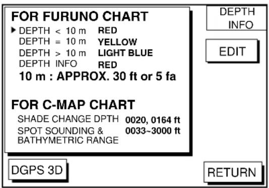
Figure 11-20 DEPTH INFO display
- Press ▲ or ▼ to select item and press the soft key EDIT or enter the appropriate value by using numeric keys.
- Select option with cursor pad and press the soft key ENTER or the [ENTER] key.
- Press the soft key RETURN several times to finish.
SHADE CHANGE DPTH: Sets two
values in the range of Depth Limit on the DEPTH INFO display when the C-MAP NT-FP chart is used. The Depth Areas are shown on the screen in three colors depending on depth.
0 to left value: Blue left value to right value: Light-blue greater than right value: Light-gray (Maximum value: 12000 meter or 39369 ft)
In Figure 11-20, as the following,
0 - 20 ft: Blue 20 - 164 ft: Light-blue greater than 164 ft: Light-gray
Note 1: Depth data depends on the registered value at "depth area". (See page 1.)
Note 2: It may be difficult to distinguish colors of track and mark/line in sea areas painted in light-blue or green.
SPOT SOUNDING &
BATHYMETRIC RANGE: Sets the depth range to display the spot sounding on the C-MAP NT-FP chart. The depth range you set is displayed red.
11.6 Selecting Chart Scale/Range
Chart scale (range) may be selected with the soft key ZOOM IN or ZOOM OUT. ZOOM IN expands the chart; ZOOM OUT shrinks it. The range selected is momentarily displayed at the lower left-hand corner.
Note: When the display is expanded or shrunk beyond the range of the chart card in use the chart is not displayed, and an appropriate chart icon appears.
11.7 Displaying Program Number
- Press the [MENU] key to open the main menu.
- Press the soft key CONFIGURATION to show the configuration menu.
- Press the soft key SYSTEM MENU to open the system menu.
- Press the soft key SELF TEST to open the test menu.
- Press the soft key MEMORY, I/O TEST to start the test. Test results and program numbers. are shown as below.

flowchart
graph TD
    A["Program Number"] --> B["PROGRAM: OK\nNo.14518400*"]
    A --> C["SRAM: OK"]
    A --> D["DRAM: OK"]
    A --> E["PORT1: ---\nPORT2: ---"]
    A --> F["INTERNAL\nBATTERY: OK"]
    A --> G["GPS\nRECEIVER: OK\nNo.48502170*"]
    A --> H["BEACON\nRECEIVER: OK\nNo.08501820*"]
    B --> I["TEST"]
    C --> I
    D --> I
    E --> I
    F --> I
    G --> I
    H --> I
    I --> J["RETURN"]
Figure 11-21 Memory, I/O test results
12.1 Maintenance
Regular maintenance is essential for good performance. A maintenance program should be established and should at least include the items listed in Table 12-1.

WARNING

Do not open the equipment.
Hazardous voltage which can cause electrical shock, burn or serious injury exists inside the equipment. Only qualified personnel should work inside the equipment.
Table 12-1 Recommended maintenance program
| metl | t | niopkcehC |
| amte | Check for loosened and corroded obs. | Tighten loosened bolts. Replace heavily corroded bolts. |
| Antenna cable | Check connection point for watertightness. | Replace damaged parts. |
| Check connector for tightness and corrosion. | ||
| Check cables for damage. | ||
| Display unit eotsec | Check for tight connection. | Tighten loosened connectors. |
| Ground terminal | Check for tight connection and corrosion. | Clean or replace as necessary. |
| Display unit | Dust and foreign material on the display unit and screen. | Dust on the display dims the picture. Dust may be removed with a soft cloth. if necessary anti-static cleaner may be used. Never use chemical solvents to clean the display; they can remove paint and markings. |
12.2 Replacement of Fuse, Battery
The fuse on the power cable protects the system from reverse polarity of the ship's mains and equipment fault. If the fuse blows, find the cause before replacing it. Use only a 3A fuse. Using the wrong fuse will damage the unit and void the warranty.

CAUTION
Use the correct fuse.
Use of a wrong fuse can cause fire or equipment damage.
A battery installed on a circuit board inside display unit preserves data when the power is turned off. The life of the battery is about three years. When the battery voltage is low the battery icon (☐) appears on the display. When this happens, contact your dealer to request replacement of the battery.
| Type | Code Number | |
| idim | CR2450-F2 ST2 | 000-133-495 |
12.3 Simple Troubleshooting
Below are simple troubleshooting procedures which the user can follow to restore normal operation.
Table 12-2 Simple troubleshooting (plotter)
| ...fl | . |
| rewopehth | .esufnwolbrofshc |
| check that the power connector is firmly tightened. | |
| check for a crosion on power cable connector. | |
| check for damaged power cable. | |
| check battery for proper voltage output (10.2 to 31.2 V). | |
| sraeppaaghtontupondewon | press the [POWER/BRILL] key briefly and the cursor pad to adjust display brilliance and tone. |
| there is no response when a key is eagle | iagarewedtnonrut |
| position is not fixed within 3 minutes. | check for loosened antenna connector. |
| check for frequency deviation of GPS receiver on GPS monitor display. | |
| check GPS receiver status indicaion. | |
| position is wrong | check that the correct geodetic chart system is selected on the GPS/DGPS/TD OPTIONS menu. |
| enter GPS position offset on the GPS/DGPS/TD OPTIONS .unem | |
| track is not plotted | plotting is stopped. ("H" appears on the plotter display.) |
| bearing is wrong | check that correct magnetic variation is entered on the DISPLAY OPTIONS menu. |
| Loran or Decca TDs do not appear | check that proper Loran or Decca chain codes are entered on the GPS/DGPS/TD OPTIONS menu. |
| Loran TDs are wrong | enter TD offset on the GPS/DGPS/TD OPTIONS menu. |
| ship's speed display is not zero after ship is stopped | try to decrease GPS speed smoothing setting on the GPS/DGPS/TD OPTIONS menu. |
12.4 Error Messages
This equipment displays the following error messages on the alarm menu to alert you to possible trouble.
Table 12-4 Error messages
| egasse | MrorrE |
| XOPG | No GPS signal.Check antenna cable. |
| LANERENDGPS CORRECTION.Iy0581-PG( | No DGPS signal.Check antenna. |
| FOXINTERNAL BATTERY ISLOW | lanforbattery is low.nemabfo |
12.5 Diagnostic Tests
Memory, I/O port test
This test conducts a general check of the display unit and the antenna unit. The unit displays the results for each device or component checked as OK or NG (No Good).
- Press the [MENU] key to open the main menu.
- Press the soft key CONFIGURATION to show the configuration menu.
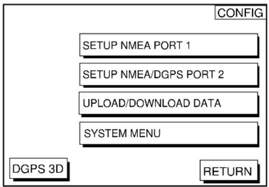
flowchart
graph TD
    A["CONFIG"] --> B["SETUP NMEA PORT 1"]
    A --> C["SETUP NMEA/DGPS PORT 2"]
    A --> D["UPLOAD/DOWNLOAD DATA"]
    A --> E["SYSTEM MENU"]
    F["DGPS 3D"] --> G["RETURN"]
Figure 12-1 Configuration menu
- Press the soft key SYSTEM MENU to open the system menu.
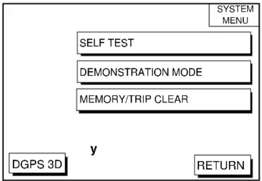
flowchart
graph TD
    A["SYSTEM MENU"] --> B["SELF TEST"]
    B --> C["DEMONSTRATION MODE"]
    C --> D["MEMORY/TRIP CLEAR"]
    D --> E["y"]
    E --> F["DGPS 3D"]
    E --> G["RETURN"]
Figure 12-2 System menu
- Press the soft key SELF TEST to open the test menu.
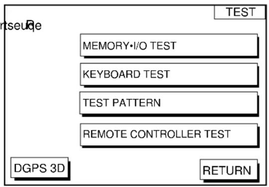
flowchart
graph TD
    A["DGPS 3D"] --> B["MEMORY•I/O TEST"]
    B --> C["KEYBOARD TEST"]
    C --> D["TEST PATTERN"]
    D --> E["REMOTE CONTROLLER TEST"]
    E --> F["RETURN"]
    G["TEST"] --> H["Return"]
Figure 12-3 Test menu
- Press the soft key MEMORY•I/O TEST to start the test. The test results appear as below.
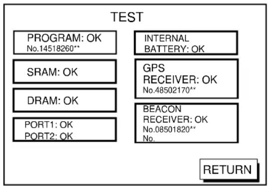
: Special connections are required to check these ports.
Otherwise, "--" appears.
**: Program Version No.
Figure 12-4 Memory, I/O test results
- The test runs continuously. To return to the self test menu, press the soft key RETURN.
Note: BEACON RECEIVER results only appear on GP-1850D.
Keyboard test
This test checks all controls for proper operation.
- Press the [MENU] followed by the soft keys CONFIGURATION, SYSTEM MENU and SELF TEST to display the self test menu.
- Press the soft key KEYBOARD TEST to display the screen for testing the keyboard.
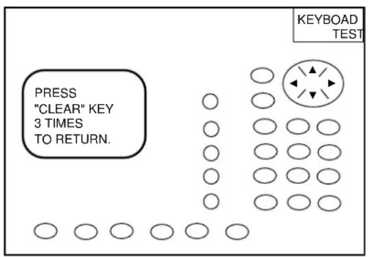
Figure 12-5 Keyboard test
-
Press any key. The pressed key's on-screen location turns black if the key is functioning properly.
-
To escape, press the [CLEAR] key three times.
Display test
- Press the [MENU] key followed by the soft keys CONFIGURATION, SYSTEM MENU and SELF TEST to display the self test menu.
- Press the soft key TEST PATTERN to open the test pattern display.
- Press the [ENTER] key to change the test pattern.
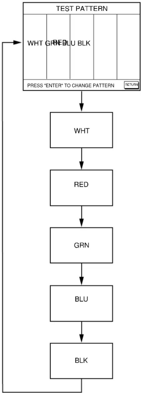
flowchart
graph TD
    A["BLK"] --> B["BLU"]
    B --> C["GRN"]
    C --> D["RED"]
    D --> E["WHT"]
    E --> F["PRESS "ENTER" TO CHANGE PATTERN"]
    F --> G["RETURN"]
    G --> H["TEST PATTERN"]
    style A fill:#f9f,stroke:#333
    style H fill:#ccf,stroke:#333
Figure 12-6 Display test pattern
Remote controller test
This test checks the controls of the remote controller for proper operation.
- Press the [MENU] key followed by the soft keys CONFIGURATION, SYSTEM MENU and SELF TEST to display the self test menu.
- Press the soft key REMOTE CONTROLLER TEST to display the screen for testing the remote controller.
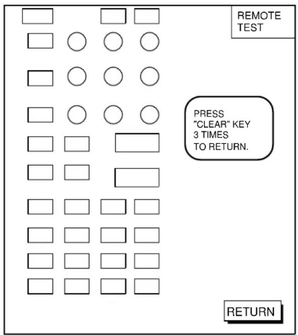
Figure 12-7 Remote controller test
- Press the any key. The pressed key's on-screen location turns black if the key is functioning properly.
- To escape, press the soft key RETURN on the display unit, or press the [CLEAR] key three times on the remote controller.
12.6 Clearing Memories
The memory, which stores marks, tracks and initial settings, can be cleared to start afresh. When this done all default settings are restored.
-
Press the [MENU] key followed by the soft keys CONFIGURATION and SYSTEM MENU.
-
Press the soft key MEMORY/TRIP CLEAR to open the clear memory menu.
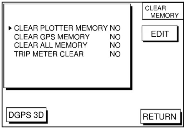
Figure 12-8 Clear memory menu
- Press ▲ or ▼ to select memory/trip to clear.
- Press the soft key EDIT.
- Press ▲ to select YES.
- Press the soft key ENTER or the [ENTER] key to clear memory selected.
Note: For PLOTTER MEMORY and CLEAR ALL MEMORY, all waypoints and routes are cleared and default settings are restored. If you require this data, save it to a PC.
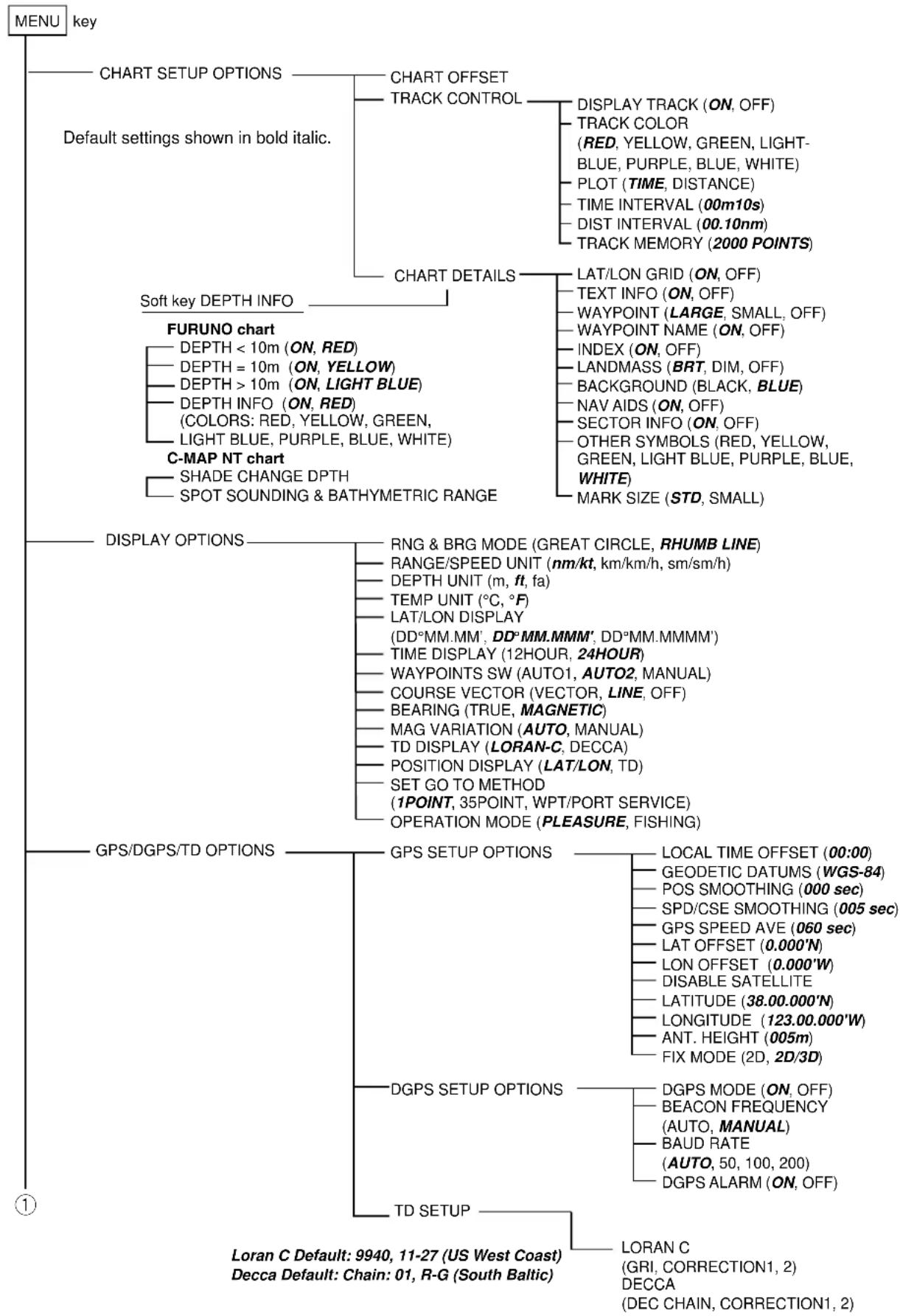
flowchart
graph TD
    A["MENU key"] --> B["CHART SETUP OPTIONS"]
    A --> C["Default settings shown in bold italic."]
    A --> D["Soft key DEPTH INFO"]
    A --> E["FURUNO chart"]
    A --> F["C-MAP NT chart"]
    A --> G["DISPLAY OPTIONS"]
    A --> H["GPS/DGPS/TD OPTIONS"]
    A --> I["TD SETUP"]

    B --> B1["CHART OFFSET"]
    B --> B2["TRACK CONTROL"]
    B1 --> B1a["DISPLAY TRACK (ON, OFF)"]
    B1 --> B1b["TRACK COLOR (RED, YELLOW, GREEN, LIGHT-BLUE, PURPLE, BLUE, WHITE)"]
    B1 --> B1c["PLOT (TIME, DISTANCE)"]
    B1 --> B1d["TIME INTERVAL (00m10s)"]
    B1 --> B1e["DIST INTERVAL (00.10nm)"]
    B1 --> B1f["TRACK MEMORY (2000 POINTS)"]

    C --> C1["CHART DETAILS"]
    C1 --> C1a["LAT/LON GRID (ON, OFF)"]
    C1 --> C1b["TEXT INFO (ON, OFF)"]
    C1 --> C1c["WAYPOINT (LARGE, SMALL, OFF)"]
    C1 --> C1d["WAYPOINT NAME (ON, OFF)"]
    C1 --> C1e["INDEX (ON, OFF)"]
    C1 --> C1f["LANDMASS (BRT, DIM, OFF)"]
    C1 --> C1g["BACKGROUND (BLACK, BLUE)"]
    C1 --> C1h["NAV AIDS (ON, OFF)"]
    C1 --> C1i["SECTOR INFO (ON, OFF)"]
    C1 --> C1j["OTHER SYMBOLS (RED, YELLOW, GREEN, LIGHT BLUE, PURPLE, BLUE, WHITE)"]
    C1 --> C1k["WHITE"]
    C1 --> C1l["MARK SIZE (STD, SMALL)"]

    E --> E1["RNG & BRG MODE (GREAT CIRCLE, RHUMB LINE)"]
    E --> E2["RANGE/SPEED UNIT (nm/kt, km/km/h, sm/sm/h)"]
    E --> E3["DEPTH UNIT (m, ft, fa)"]
    E --> E4["TEMP UNIT (°C, °F)"]
    E --> E5["LAT/LON DISPLAY (DD°MM.MM', DD°MM.MMM', DD°MM.MMMM')"]
    E --> E6["TIME DISPLAY (12HOUR, 24HOUR)"]
    E --> E7["WAYPOINTS SW (AUTO1, AUTO2, MANUAL)"]
    E --> E8["COURSE VECTOR (VECTOR, LINE, OFF)"]
    E --> E9["BEARING (TRUE, MAGNETIC)"]
    E --> E10["MAG VARIATION (AUTO, MANUAL)"]
    E --> E11["TD DISPLAY (LORAN-C, DECCA)"]
    E --> E12["POSITION DISPLAY (LAT/LON, TD)"]
    E --> E13["SET GO TO METHOD (1POINT, 35POINT, WPT/PORT SERVICE)"]
    E --> E14["OPERATION MODE (PLEASURE, FISHING)"]

    G --> G1["GPS SETUP OPTIONS"]
    G1 --> G1a["LOCAL TIME OFFSET (00:00)"]
    G1 --> G1b["GEODETIC DATUMS (WGS-84)"]
    G1 --> G1c["POS SMOOTHING (000 sec)"]
    G1 --> G1d["SPD/CSE SMOOTHING (005 sec)"]
    G1 --> G1e["GPS SPEED AVE (060 sec)"]
    G1 --> G1f["LAT OFFSET (0.000'N)"]
    G1 --> G1g["LON OFFSET (0.000'W)"]
    G1 --> G1h["DISABLE SATELLITE"]
    G1 --> G1i["LATITUDE (38.00.000'N)"]
    G1 --> G1j["LONGITUDE (123.00.000'W)"]
    G1 --> G1k["ANT. HEIGHT (005m)"]
    G1 --> G1l["FIX MODE (2D, 2D/3D)"]

    H --> H1["DGPS SETUP OPTIONS"]
    H1 --> H1a["DGPS MODE (ON, OFF)"]
    H1 --> H1b["BEACON FREQUENCY (AUTO, MANUAL)"]
    H1 --> H1c["BAUD RATE (AUTO, 50, 100, 200)"]
    H1 --> H1d["DGPS ALARM (ON, OFF)"]

    I --> I1["Loran C Default: 9940, 11-27 (US West Coast)"]
    I --> I2["Decca Default: Chain: 01, R-G (South Baltic)"]

    I --> I3["Loran C (GRI, CORRECTION1, 2)"]
    I --> I4["DECCA (DEC CHAIN, CORRECTION1, 2)"]
①
Default settings shown in bold italic.
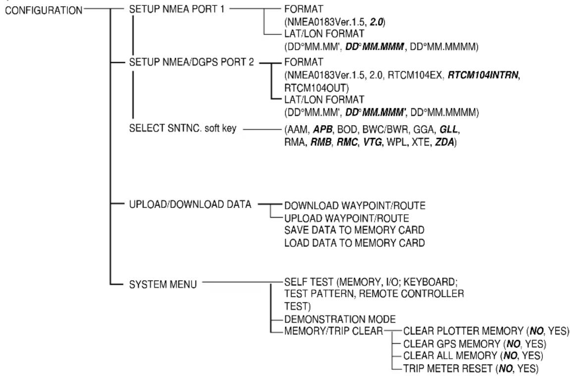
flowchart
graph TD
    A["CONFIGURATION"] --> B["SETUP NMEA PORT 1"]
    B --> C["FORMAT (NMEA0183Ver.1.5, 2.0)<br>LAT/LON FORMAT (DD°MM.MM', DD°MM.MMM, DD°MM.MMMM)"]
    A --> D["SETUP NMEA/DGPS PORT 2"]
    D --> E["FORMAT (NMEA0183Ver.1.5, 2.0, RTCM104EX, RTCM104INTRN, RTCM104OUT)<br>LAT/LON FORMAT (DD°MM.MM', DD°MM.MMM', DD°MM.MMMM)"]
    A --> F["SELECT SNTNC. soft key"]
    F --> G["(AAM, APB, BOD, BWC/BWR, GGA, GLL, RMA, RMB, RMC, VTG, WPL, XTE, ZDA)"]
    A --> H["UPLOAD/DOWNLOAD DATA"]
    H --> I["DOWNLOAD WAYPOINT/ROUTE<br>UPLOAD WAYPOINT/ROUTE<br>SAVE DATA TO MEMORY CARD<br>LOAD DATA TO MEMORY CARD"]
    A --> J["SYSTEM MENU"]
    J --> K["SELF TEST (MEMORY, I/O; KEYBOARD;<br>TEST PATTERN, REMOTE CONTROLLER TEST)"]
    J --> L["DEMONSTRATION MODE<br>MEMORY/TRIP CLEAR"]
    L --> M["CLEAR PLOTTER MEMORY (NO, YES)"]
    L --> N["CLEAR GPS MEMORY (NO, YES)"]
    L --> O["CLEAR ALL MEMORY (NO, YES)"]
    L --> P["TRIP METER RESET (NO, YES)"]
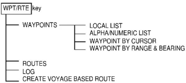
flowchart
graph TD
    A["WPT/RTE key"] --> B["WAYPOINTS"]
    B --> C["LOCAL LIST"]
    B --> D["ALPHA/NUMERIC LIST"]
    B --> E["WAYPOINT BY CURSOR"]
    B --> F["WAYPOINT BY RANGE & BEARING"]
    B --> G["ROUTES"]
    B --> H["LOG"]
    B --> I["CREATE VOYAGE BASED ROUTE"]
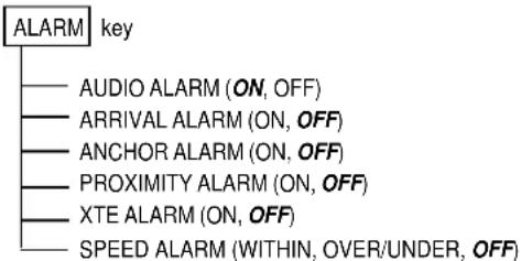
| Chain | GRI | S1 | S2 | S3 | S4 | S5 |
| Central Pacific | 4990 | 11 | 29 | - | - | - |
| Canadian East Coast | 5930 | 11 | 25 | 38 | - | - |
| Commando Lion (Korea) | 5970 | 11 | 31 | 42 | - | - |
| Canadian West Coast | 5990 | 11 | 27 | 41 | - | - |
| South Saudi Arabia | 7170 | 11 | 26 | 39 | 52 | - |
| Labrador Sea | 7930 | 11 | 26 | - | - | - |
| Eastern Russia | 7950 | 11 | 30 | 46 | 61 | - |
| Gulf of Alaska | 7960 | 11 | 26 | 44 | - | - |
| Norwegian Sea | 7970 | 11 | 26 | 46 | 60 | - |
| Southeast USA | 7980 | 11 | 23 | 43 | 59 | - |
| Mediterranean Sea | 7990 | 11 | 29 | 47 | - | - |
| Western Russia | 8000 | 10 | 25 | 50 | 65 | - |
| North Central USA | 8290 | 11 | 27 | 42 | - | - |
| North Saudi Arabia | 8990 | 11 | 25 | 40 | 56 | 69 |
| Great Lakes | 8970 | 11 | 28 | 44 | 59 | - |
| South Central USA | 9610 | 11 | 25 | 40 | 52 | 65 |
| West Coast USA | 9940 | 11 | 27 | 40 | - | - |
| Northeast USA | 9960 | 11 | 25 | 39 | 54 | - |
| Northwest Pacific (old) | 9970 | 11 | 30 | 55 | 81 | - |
| Icelandic | 9980 | 11 | 30 | - | - | - |
| North Pacific | 9990 | 11 | 29 | 43 | - | - |
| Suez | 4991 | 10 | 24 | |||
| England, France | 8940 | 12 | 30 | |||
| Northwest Pacific | 8930 | 11 | 30 | 50 | 70 | |
| Newfoundland East Coast | 7270 | 11 | 25 | |||
| Lessay | 6731 | 10 | 39 | |||
| B∅ | 7001 | 11 | 27 | |||
| Sylt | 7499 | 11 | 26 | |||
| Ejde | 9007 | 10 | 23 | 38 | ||
| Saudia Arabia North | 8830 | 11 | 25 | 39 | 56 | |
| Saudia Arabia South | 7030 | 11 | 25 | 37 | 55 |
| niah No. | C niahC | code | n noitacoL | i no. | niahCn | a code | n inoitacoL h |
| 01 | South Baltic | 0A | Europe | 34 | Kanto | 8C | Japan |
| 02 | Vestlandet | 0E | " | 35 | Shikoku | 4C | " |
| 03 | Southwest British | 1B | " | 36 | Hokuriku | 2C | " |
| 04 | Northumbrian | 2A | " | 37 | Kita Kyushu | 7C | " |
| 05 | Holland | 2E | " | 38 | Namaqualand | 4A | Southern Africa |
| 06 | North British | 3B | " | 39 | Cape | 6A | " |
| 07 | Lofoten | 3E | " | 40 | Eastern Province | 8A | " |
| 08 | 3F | " | 41 | South West Africa | 9C | " | |
| 09 | North Baltic | 4B | " | 42 | Natal | 10C | " |
| 10 | North West | 4C | " | 43 | Dampier | 8E | Australia |
| 11 | Trondelag | 4E | " | 44 | Port Headland | 4A | " |
| 12 | English | 5B | " | 45 | Anticosti | 9C | Northern America |
| 13 | North Bothnian | 5F | " | 46 | East Newfoundland | 2C | " |
| 14 | Southern Spanish | 6A | " | 47 | Cabot Strait | 6B | " |
| 15 | North Scottish | 6C | " | 48 | Nova Scotia | 7C | " |
| 16 | Gulf of Finland | 6E | " | ||||
| 17 | Danish | 7B | " | ||||
| 18 | Irish | 7D | " | ||||
| 19 | Finnmark | 7E | " | ||||
| 20 | French | 8B | " | ||||
| 21 | South Bothnian | 8C | " | ||||
| 22 | Hebridean | 8E | " | ||||
| 23 | Frisian Islands | 9B | " | ||||
| 24 | Helgeland | 9E | " | ||||
| 25 | Skagerrak | 10B | " | ||||
| 26 | North Persian Gulf | 5C | Persian Gulf & India | ||||
| 27 | South Persian Gulf | 1C | " | ||||
| 28 | Bombay | 7B | " | ||||
| 29 | Calcutta | 8B | " | ||||
| 30 | Bangladesh | 6C | " | ||||
| 31 | Saliyah | 2F | " | ||||
| 32 | Hokkaido | 9C | Japan | ||||
| 33 | Tohoku | 6C | " |
i a
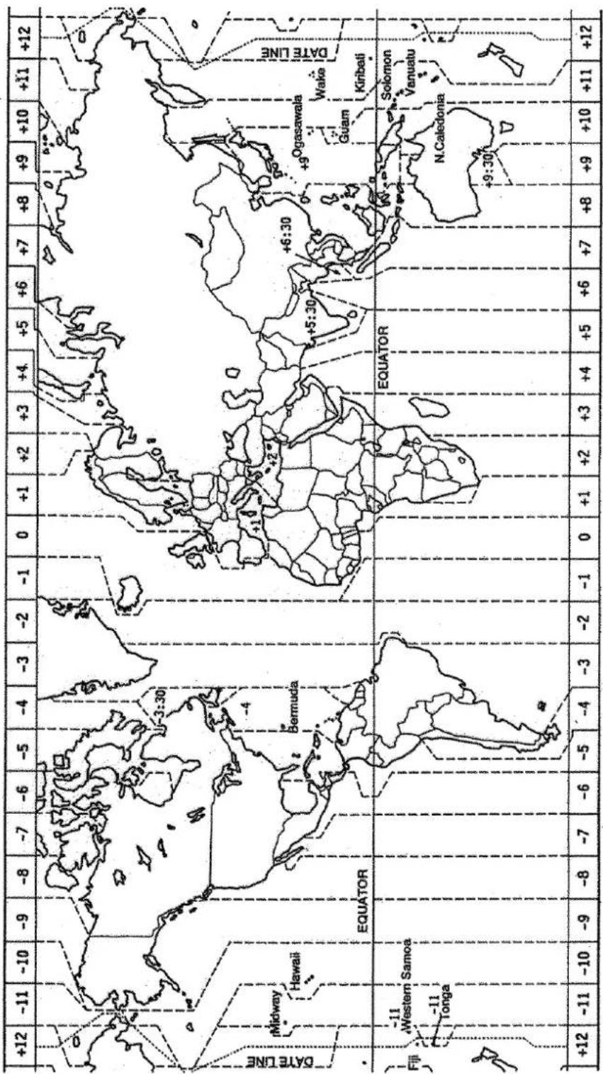
geo
| Region | Equator Equation | |---|---| | Midway | Hawaii | | Bermuda | Equator Equator | | Fiji | Western Samoa | | Tonga | Equator Equator | | Equator Equator | Solomon Vanuatu | | Guam | Kiribati | | N.Caledonia | Solomon Vanuatu | | +12 | -11 | | -10 | -9 | | -8 | -7 | | -6 | -5 | | -4 | -3 | | -2 | -1 | | 0 | +1 | | +1 | +2 | | +3 | +4 | | +5 | +6 | | +7 | +8 | | +9 | +10 | | +11 | +12 | | +12 | -11 | | -3:30 | -3:30 | | +5:30 | +6:30 | | +9:30 | +9:30 | +9:30 (EQUATOR) |001: WGS84
002: WGS72
003: TOKYO
004: NORTH AMERICAN 1927 : Mean Value (CONUS)
005: EUROPEAN 1950 : Mean Value
006: AUSTRALIAN GEODETIC 1984 : Australia & Tasmania
007: ADINDAN-MN
008: ADINDAN-E : Ethiopia
009: ADINDAN-MA : Mali
010: ADINDAN-SE : Senegal
011 ADINDAN-SU : Sudan
012: AFG : Somalia
013: AIN EL ABD 1970 ; Bahrain Is.
014: ANNA 1 ASTRO 1965 : Cocos Is.
015: ARC 1950-MN
016: ARC 1950-B
017: ARC 1950-L : Lesotho
018: ARC 1950-M
019: ARC 1950-S
020: ARC 1950-ZR
021: ARC 1950-ZM : Zambia
022: ARC 1950-ZB : Zimbabwe
023: ARC 1960-MN
024: ARC 1960-K
025: ARC 1960-T
026: ASCENSION IS. 1958
027: ASTRO BEACON "E"
028: ASTRO B4 SOR. ATOLL
029: ASTRO POS 71/4
030: ASTRONOMIC STATION 1952
031: AUSTRALIAN GEODETIC 1966 : Australia & Tasmania
032: BELLEVUE (IGN)
033: BERMUDA 1957
034: BOGOTA OBSERVATORY
035: GAUPO INCHAUSPE : Argentina
036: CANTON IS. 1966
037: CAPE
038: CAPE CANAVERAL
039: CARTHAGE
040: CHATHAM 1971
041: CHUA ASTRO
042: CORREGO ALEGRE
043: DJAKARTA (BATAVIA)
044: DOS 1968
045: EASTER IS. 1967
046: EUROPEAN 1950-WE
047: EUROPEAN 1950-CY
048: EUROPEAN 1950-EG
049: EUROPEAN 1950-ESC
050: EUROPEAN 1950-EIS
051: EUROPEAN 1950-GR
052 EUROPEAN 1950-IR
053: EUROPEAN 1950-SA
054: EUROPEAN 1950-SI
055: EUROPEAN 1950-NF
056: EUROPEAN 1950-PS
057: EUROPEAN 1979 : Mean Value
058: GANDAJIKA BASE
059: GEODETIC DATUM 1949
060: GUAM 1963 : Guam Is.
061: GUX 1 ASTRO
062: HJORSEY 1955
063: HONG KONG 1363
064: INDIAN-TV
065: INDIAN-BIN
066: IRELAND 1965
067: ISTS 073 ASTRO 1969
068: JOHNSTON IS, 1961
069: KANDAWALA : Sri Lanka
070: KERGUELEN IS.
071: KERTAU 1948
072: LA REUNION
073: L. C. 5 ASTRO
074: LIBERIA 1964 : Liberia
075: LUZON
076: LUZON-M
077: MAHE 1971
078: MARCO ASTRO
079: MASSAWA
080: MERCHICH
081: MIDWAY ASTRO 1961
082: MINNA
083: NAHRWAN-O : Masirah Is. (Oman)
084: NAHRWAN-UAE
085: NAHRWAN-SA
086: NAMIBIA
087: MAPARIMA, BWI
088: NORTH AMERICAN 1927WU
089: NORTH AMERICAN 1927EU
090: NORTH AMERICAN 1927AK
091: NORTH AMERICAN 1927BH
092: NORTH AMERICAN 1927SS
093: NORTH AMERICAN 1927CN
Mean Value (Japan, Korea & Okinawa)
lue (CONUS)
•
stralia & Tasmania
Mean Value (Ethiopia & Sudan)
: Mean Value
Botswana
Malawi
Swaziland
Zaire
: Mean Value (Kenya & Tanzania)
Kenya
: Tanzania
Ascension Is.
Iwo Jima Is.
: Tern Is.
St. Helena Is.
: Marcus Is.
stralia & Tasmania
: Efate & Erromango Islands
Bermuda Islands
: Columbia
Phoenix Islands
South Africa
: Mean Value (Florida & Bahama Islands)
Tunisia
: Chatham Is. (New Zealand)
: Paraguay
Brazil
: Sumatra Is. (Indonesia)
: Gizo Is. (New Georgia Is.)
Easter Is.
Western Europe
Cyprus
Egypt
: England, Scotland, Channel & Shetland Islands
: England, Ireland, Scotland, & Shetland Islands
: Greece
: Iran
Italy, Sardinia
: Italy, Sicily
Norway & Finland
: Portugal & Spain
: Republic of Maldives
: New Zealand
: Guadalcanal Is.
Iceland
Hong Kong
: Thailand & Vietnam
: Bangladesh, India & Nepal
Ireland
: Diego Garcia
: Johnston Is.
: Kerguelen Is.
: West Malaysia & Singapore
Mascarene Is.
: Cayman Brac Is.
: Philippines (excl. Mindanao Is.)
Mindanao Is.
: Mahe Is.
Salvage Islands
: Eritrea (Ethiopia)
Morocco
: Midway Is.
Nigeria
: United Arab Emirates
Saudi Arabia
: Namibia
: Trinidad & Tobago
Western United States
: Eastern United States
Alaska
Bahamas (excl. San Salvador Is.)
: Bahamas, San Salvador Is
Canada (incl. Newfoundland Is.)
094: NORTH AMERICAN 1927AB
095: NORTH AMERICAN 1927EC
096: NORTH AMERICAN 1927MC
097: NORTH AMERICAN 1927NE
098: NORTH AMERICAN 1927YK
099: NORTH AMERICAN 1927CZ
100: NORTH AMERICAN 1927CR
101: NORTH AMERICAN 1927CA
102: NORTH AMERICAN 1927CU
103: NORTH AMERICAN 1927GR
104: NORTH AMERICAN 1927MX
105: NORTH AMERICAN 1983AK
106: NORTH AMERICAN 1983CN
107: NORTH AMERICAN 1983CS
108: NORTH AMERICAN 1983MX
109: OBSERVATORIO 1966
110: OLD EGYPTIAN 1930
111: OLD HAWAIIAN-MN
112: OLD HAWAIIAN-HW
113: OLD HAWAIIAN-KA
114: OLD HAWAIIAN-MA
115: OLD HAWAIIAN-OA
116: OMAN
117: ORDNANCE SURVEY OF GREAT BRITAIN 1936-MN: Mean Value
118: ORDNANCE SURVEY OF GREAT BRITAIN 1936-E: England
119: ORDNANCE SURVEY OF GREAT BRITAIN 1936-IM: England, Isle
of Man & Wales
120: ORDNANCE SURVEY OF GREAT BRITAIN 1936-SSI: Scotland, &
Shetland Islands
121: ORDNANCE SURVEY OF GREAT BRITAIN 1936-WL: Wales
122: PICO DE LAS NIVIES
123: PITCAIRN ASTRO 1967 : Pitcairn Is.
124: PROVISIONS SOUTH CHILEAN 1963: South Chile (near 53° S)
125: PROVISIONAL SOUTH AMERICAN 1956MN: Mean Value
126: PROVISIONAL SOUTH AMERICAN 1956BO: Bolivia
127: PROVISIONAL SOUTH AMERICAN 1956NC: Chile-Northern Chile
128: PROVISIONAL SOUTH AMERICAN 1956SC: Chile-Southern Chile
(near 43°S)
129: PROVISIONAL SOUTH AMERICAN 1956CO
130: PROVISIONAL SOUTH AMERICAN 1956EC: Ecuador
131: PROVISIONAL SOUTH AMERICAN 1956GY: Guyana
132: PROVISIONAL SOUTH AMERICAN 1956PR: Peru
133: PROVISIONAL SOUTH AMERICAN 1956VN: Venezuela
134: PUERTO RICO
135: QATAR NATIONAL
136: QORNOQ
137: ROME 1940
138: SANTA BRAZ
139: SANTO (DOS)
140: SAPPER HILL 1943
141: SOUTH AMERICAN 1969MN
142: SOUTH AMERICAN 1969AG
143: SOUTH AMERICAN 1969BO
144: SOUTH AMERICAN 1969BR
145: SOUTH AMERICAN 1969CH
146: SOUTH AMERICAN 1969CO
147: SOUTH AMERICAN 1969EC
148: SOUTH AMERICAN 1969GY
149: SOUTH AMERICAN 1969PA
150: SOUTH AMERICAN 1969PR
151: SOUTH AMERICAN 1969TT
152: SOUTH AMERICAN 1969VZ
153: SOUTH ASIA
154: SOUTHEAST BASE
155: SOUTHWEST BASE
156: TIMBALAI 1948
157: TOKYO JP
158: TOKYO KP
159: TOKYO OK
160: TRISTAN ASTRO 1968
161: VITI LEVU 1916
162: WAKE-ENIWETOK 1960
163: ZANDERIJ
164: BUKIT RIMPAH
165: CAMP AREA ASTRO
166: G. SEGARA
167: HERAT NORTH
168: HU-TZU-SHAN
169: TANANARIVE OBSERVATORY 1925
170: YACARE
171: RT-90
172: Pulkovo 1942
173: Finish KKJ
: Alberta & British Columbia
East Canada
: Manitoba & Ontario
Northwest Territories & Saskatchewan
Yukon
: Canal Zone
: Caribbean
: Central America
: Cuba
: Greenland
: Mexico
Alaska
: Canada
CONUS
Mexico, Central America
: Corvo & Flores Islands (Azores)
Egypt
: Mean Value
: Hawaii
: Kauai
: Maui
: Oahu
Omar
RITAIN 1936-MN: Mean Value
RITAIN 1936-E: England
RITAIN 1936-IM: England, Isle
of Man & Wales
RITAIN 1936-SSI: Scotland, &
Shetland Islands
RITAIN 1936-WL: Wales
Canary Islands
Pitcairn Is.
3: South Chile (near 53° S)
1956MN: Mean Value
1956BO: Bolivia
1956NC: Chile-Northern Chile
(near 19°S)
1956SC: Chile-Southern Chile
(near 43'S)
1956CO: Columbia
1956EC: Ecuador
1956GY: Guyana
1956PR: Peru
1956VN: Venezuela
Puerto Rico & Virgin Islands
: Qatar
South Greenland
Sardinia Islands
: Sao Maguel, Santa Maria Islands (Azores)
Espirito Santo Is.
East Falkland Is.
Mean Value
Argentina
Bolivia
Brazil
Chile
Columbia
SPECIFICATIONS OF
COLOR GPS/ PLOTTER: GP-1850
COLOR DGPS/ PLOTTER: GP-1850D
1. GENERAL
(1) Display 6.5 inch high resolution color LCD
(2) Projection Mercator
(3) Usable Area 85° latitude or below
(4) Display Mode Plotter, Video pilot, Highway display, Waypoint display
(5) Alarms Arrival and Anchor watch, Cross track error and proximity alarms,
Ship's speed in and out alarms
2. GPS RECEIVER
(1) Receiving Channels 12 channels parallel, 12 satellite tracking
(2) Rx Frequency 1575.42 MHz
(3) Rx Code C/A code
(4) Position Fixing System All in view, 8-state Kalman filter
(5) Position Accuracy Approx. 10 m, 95% of the time,
horizontal dilution of position (HDOP) ≤1
Note: All GPS receiver are subject to degradation of position and velocity accuracy under the U.S. Department of Defense.
Position may be degraded.
DGPS: approx. less than 5 m, 95% of the time
(6) Tracking Velocity 900 kts
(7) Position-fixing Time Warm start: 12 seconds, Cold start: 90 seconds
(8) Position Update Interval 1 second
(9) DGPS Data Receiving RTCM SC-104 Ver 2.1 formatted
(External DGPS data required for GP-1850)
3. DISPLAY SECTION
(1) Effective area 133.4·97.3 mm
(2) Display pixels 234-320 dots
(3) Position Indication Latitude/longitude or Loran C LOP or DECCA LOP
4. PLOTTER
(1) Effective Projection Area 0.125 nm to 2,048 nm (at equatorial area)
(2) Track Display Plot interval: by time (0 to 99 min. 59 sec.) or
by distance (0 to 99.99 nm)
(3) Colors Red, yellow, green, purple, light-blue, blue, white
(4) Memory Capacity Track/Mark: 5000 points, Waypoint: 800 points
(5) Storage Capacity Simple route: 200 routes with 35 waypoints each
(6) MOB 1 point
(7) Quick routes 1 course with 35 waypoints max.
(8) Electronic Chart FURUNO chart card or NAVIONICS chart card available C-MAP chart card also available for C-MAP NT Model
5. DATA INPUT / OUTPUT
(1) Input data IEC61162-1 and NMEA0183 Ver1.5 adopted \**TLL, \**DPT, \**DBT, \**MTW, SGPWPL
(2) Output data IEC61162-1 or NMEA0183 Ver1.5 selected GPAAM , GPAPB , GPBOD , GPBWR/GPBWC , GPGLL , GPGGA , GPRMA , GPRMB , GPRMC , GPVTG , GPWPL , GPXTE , GPZDA
6. POWER SOURCE
(1) For DC Source
GP-1850: 12-24 VDC: 1.2-0.6 A max.
GP-1850D: 12-24 VDC: 1.3-0.7 A max.
(2) For AC Source 100/110/115/200/220/230 VAC, 1 phase, 50/60 Hz (optional rectifier required)
7. ENVIRONMENTAL CONDITIONS
(1) Useable Temperature Antenna unit: -25^ to +70^ Display unit: -15^ to +55^
(2) Relative Humidity 90% (40°C)
(3) Waterproofing Antenna unit: IEC60529 IPX6
Display unit: IEC60529 IPX5
8. COATING COLOR
(1) Display Unit Cover: Munsell 2.5GY5/1.5
Panel: N3.0
(2) Antenna Unit N9.5
A
Alarm information window 8-4
Alarm messages 8-4
Alarms
alarm information window 8-4
alarm message 8-4
anchor watch alarm 8-2
arrival alarm 8-1
audio alarm 8-1
DGPS alarm 10-6
proximity alarm 8-3
speed alarm 8-3
XTE alarm 8-2
Anchor watch alarm 8-2
Antenna height 10-5
Arrival alarm 8-1
Audio alarm 8-1
Auto course-up mode 2-1
B
Background color
chart 10-2
Battery replacement 12-2
Beacon baud rate 10-6
Beacon frequency 10-6
Beacon information display 2-6
Brilliance adjustment 1-4
Buoy data 2-4
C
Chart details menu 10-2
Chart offset menu 10-1
Chart scale 2-2
Chart setup options menu 10-1-10-2
Configuration menu 10-7-10-11
Course vector 10-3
Course-up mode 2-1
Cross-track error alarm. See XTE alarm
Cursor 2-2
Cursor data 11-1
D
Decca chains A-4
DECCA station selection 10-6
Demonstration display 1-6
Depth info 10-2
DEPTH INFO soft key 10-2
Depth unit 10-3
DGPS alarm 10-6
DGPS beacon information display 2-6
DGPS mode 10-6
DGPS setup options mode 10-5–10-7
Diagnostics
display test 12-4
keyboard test 12-4
memory, I/O test 12-3
remote controller test 12-5
Disable satellite 10-5
Display options menu 10-2–10-4
Display setup menu 10-2-10-4
Display test 12-4
Downloading data 10-9
E
Error messages 12-3
F
Fix mode 10-5
Fuse replacement 12-2
G
Geodetic datum 10-4
GPS position offset 10-5
GPS satellite monitor display 2-5
GPS/DGPS/TD options menu 10-4-10-7
Great circle 10-2
Grid 10-2
H
Highway display 2-7
|
Indications
enlargement of nav data 2-5
K
Keyboard test 12-4
L
Lat/lon display resolution 10-3
Lighthouse data 2-4
Local time 10-4
Loran C chains A-3
Loran C station selection 10-6
M
Magnetic bearing 10-3
Magnetic variation 10-3
Maintenance 12-1
Mark
color 4-2
displaying 4-3
entering 4-1
erasing 4-2
line 4-2
shape 4-2
Memory card
formatting 9-1
saving data 9-1
loading 9-2
Memory/trip clear 12-5
Memory, I/O port test 12-3
MENU key 1-5
Menu tree A-1-A-2
Mini chart cards
aids to navigation data 2-4
background color 10-2
buoy data 2-4
chart scale 2-2
chart symbol color 10-2
chart symbols 2-3
depth info 10-2
grid 10-2
Indices 10-2
indices 2-3
inserting 1-3
landmass color 10-2
lighthouse data 2-4
nav aids 10-2
port service icons (NAVIONICS) 2-4
text info 10-2
N
Nav data display 2-5
Navigation
cancelling 7-5
multiple quick points 7-1
ports, port service 7-2
quick points 7-1-7-5
restarting 7-3
route 7-3
route in reverse order 7-3
single quick point 7-1
specific route leg 7-3
switching route waypoints 7-4
waypoints 7-2
North-up mode 2-1
0
Object 11-1
Operation mode 2-8
P
Port services
description 2-4
navigating to 7-2, 11-3
Position format selection 10-3
Position input 10-5
Power on/off 1-3
POWER/BRILL key 1-3
Presentation modes 2-1
Program number 11-7,12-3
Proximity alarm 8-3
activating, deactivating 8-3
setting radius for individual waypoints 5-3
Q
Quick points
entry method 7-1
multiple points 7-1
single point 7-1
R
Range selection
plotter 2-2
Range unit 10-3
Remote controller
description 1-2
testing 12-5
Rhumb line 10-2
Routes
connecting (two) 6-2
entering by cursor 6-2
entering through route list 6-1
entering track based 6-4
erasing 6-5
inserting waypoints on the plotter display 6-3
inserting waypoints through route list 6-2
navigating 7-3
navigating in reverse order 7-3
navigating specific leg 7-3
removing from plotter display 6-4
removing waypoints through route list 6-3
restarting navigation of 7-3
switching waypoints 7-4
S
SAVE/MOB key 5-1
Sector info (lighthouse viewable angle) 10-2
Setup NMEA port 1 menu 10-7
Setup NMEA port 2 menu 10-8
Smoothing
position 10-4
speed/course 10-5
Soft keys 1-5
Speed
GPS speed averaging 10-5
input 7-4
unit 10-3
Speed alarm 8-3
Steering display 2-6
System configuration v
System menu 10-11
T
TD setup menu 10-6-10-7
TDs selection 10-3
Temperature unit 10-3
Tidal Information 11-2
Time
display selection 10-3
local 10-4
Trip 2-8
Tone adjustment 1-4
Track
color 3-2
displaying 3-1
erasing all 3-3
plotting interval 3-2
stopping/restarting plotting of 3-1
Track based route 6-4
Track and markpoints 4-2
Troubleshooting 12-2
U
Upload/download data menu 10-8
Uploading data 10-9
W
Waypoints
changing data 5-4
changing position at entry 5-3
changing position on plotter screen 5-5
color 5-2
comments 5-3
entering at MOB position 5-1
entering at own ship's position 5-1
entering by cursor 5-1
entering by range and bearing 5-3
erasing individual by cursor 5-4
erasing individual through waypoint list 5-4
mark size 5-5
name entry 5-3
name on/off 10-2
navigating by 7-2
proximity alarm radius 5-3
searching 5-5
shape 5-2
size 10-2
World time A-5
WPT/RTE key 5-1
X
XTE alarm 8-2
XTE scale 2-7
Pub NO. DOC-312
Declaration of Conformity
We
FURUNO ELECTRIC CO., LTD.
(Manufacturer)
9-52 Ashihara-Cho, Nishinomiya City, 662-8580, Hyogo, Japan
(Address)
declare under our sole responsibility that the product
Color GPS plotter model GP-1850
Color DGPS plotter model GP-1850D
Color GPS plotter/sounder model GP-1850F
Color DGPS plotter/sounder model GP-1850DF
(Serial No. 3420-0001 for GP-1850DF)
(Model name, serial number)
is in conformity with the essential requirements as described in the Directive 1999/5/EC of the European Parliament and of the Council of 9 March 1999 on radio equipment and telecommunications terminal equipment (R&TTE Directive) and satisfies all the technical regulations applicable to the product within this Directive
EN 60945: 1997-01 (IEC 60945 Third edition: 1996-11)
(title and/or number and date of issue of the standard(s) or other normative document(s))
For assessment, see
- Statement of Opinion N° 01214012/AA/00 of 15 January 2001 issued by KTL Certification, The Netherlands
- Test report FLI 12-99-002 of 26 January 1999 prepared by Furuno Labotech International Co., Ltd.
On behalf of Furuno Electric Co., Ltd.
Nishinomiya City, Japan January 23, 2001
Hiroaki Komatsu
Manager,
International Rules and Regulations
(Place and date of issue)
(name and signature or equivalent marking of authorized person)
- WARNING
- CAUTION
- About the TFT LCD
- FOREWORD iv
- PLOTTER DISPLAYS
- TRACK
- MARK
- WAYPOINTS
- ROUTES
- NAVIGATION
- PLOTTER ALARMS
- SAVING AND LOADING DATA TO/FROM MEMORY CARD
- CUSTOMIZING YOUR UNIT
- 11.USING C-MAP NT MODEL
- MAINTENANCE & TROUBLESHOOTING
- APPENDIX
- INDEX
- Declaration of Conformity
- A Word to GP-1850D/1850 Owners
- Features
- Display Unit Controls
- Remote Controller
- Inserting Mini Chart Card
- Turning the Power On/Off
- Turning the power off
- Adjusting Tone and Brilliance
- Displays
- Plotter display, Navigation data display
- Steering display, Highway display
- Menu Operation, Soft Keys
- Demonstration Display
- Presentation Modes
- North-up
- Course-up
- Auto course-up
- Cursor
- Turning on the cursor, shifting the cursor
- Turning off the cursor, returning own ship marker to screen center
- Shifting the Display
- Selecting Chart Scale/Range
- Mini Chart Cards
- Indices and chart enlargement
- Remarks on chart display
- Chart symbols
- Aid to navigation data
- Port service icons (Nav-Charts™ cards)
- Navigation Data Display
- Enlarging an indication
- GPS satellite monitor display
- Beacon information display
- Steering Display
- How to read the compass display
- How to read the XTE scale
- Setting the range of the XTE scale
- Highway Display
- Changing Operation Mode
- Navigation Trip Distance
- Displaying Track
- Stopping/Restarting Plotting of Track
- Changing Track Color
- Track Plotting Method, Interval
- Track plotting method
- Track plotting interval
- Changing Track Memory Capacity
- Erasing All Track
- Entering Marks
- Changing Mark Attributes
- Changing Mark Size
- Erasing Marks
- Erasing individual marks/lines
- Erasing whole marks/lines
- Displaying Track and Mark Points
- Entering Waypoints
- Entering waypoints at own ship's position
- Entering waypoints at MOB position
- Entering waypoints by the cursor
- Changing the shape and color of waypoint mark
- Changing waypoint name, comment, proximity alarm radius
- Changing waypoint position
- Entering waypoints by range and bearing
- Erasing Individual Waypoints
- Erasing waypoints by the cursor
- Erasing waypoints through the waypoint list
- Changing Waypoint Data
- Waypoint Mark Size
- Changing Waypoint Position on the Plotter Display
- Searching Waypoints
- Entering Routes
- Entering routes through the route list
- Entering routes by the cursor
- Connecting Routes
- Inserting, Removing Waypoints
- Inserting waypoints through the route list
- Inserting waypoints on the plotter display
- Inserting waypoints before the first waypoint or after the last waypoint
- Inserting waypoints in an intermediate location within a route
- Removing waypoints from routes
- Removing route waypoints through the route list
- Removing route waypoints from the plotter display
- Creating Track-based Routes
- Erasing Routes
- Navigating to "Quick Points"
- Selecting quick point entry method
- Navigating to a single quick point
- Navigating to multiple quick points
- Navigating to Waypoints (waypoint list)
- Navigating to Ports, Port Services
- Following a Route
- Navigate route waypoints in reverse order
- Navigate directly to a route waypoint
- Navigate along specific leg of route
- Restarting navigation
- Setting speed for ETA calculation
- Switching waypoints
- Cancelling Navigation
- Introduction
- Audio Alarm On/Off
- Arrival Alarm
- Anchor Watch Alarm
- XTE (Cross Track Error) Alarm
- Speed Alarm
- Proximity Alarm
- Alarm Information
- Press the [ALARM] key.
- Alarm messages
- Formatting Memory Cards
- Saving Data to Memory Card
- Saving data
- Error message
- Memory card not inserted
- Unformatted memory card
- Wrong card inserted
- Data overwrite
- Loading Data from Memory Card
- Note on loading data
- Track
- Waypoint/route
- Mark/line
- Configuration
- CHART SETUP OPTIONS menu
- CHART OFFSET menu
- TRACK CONTROL menu
- CHART DETAILS menu
- Chart details menu description
- DISPLAY OPTIONS menu
- Display setup menu description
- RNG & BRG MODE
- RANGE/SPEED UNIT
- DEPTH UNIT
- TEMP UNIT
- LAT/LON DISPLAY
- TIME DISPLAY
- WAYPOINT SW
- COURSE VECTOR
- BEARING
- MAG VARIATION
- TD DISPLAY
- POSITION DISPLAY
- SET GO TO METHOD
- OPERATION MODE
- GPS/DGPS/TD OPTIONS menu
- GPS SETUP OPTIONS menu description
- LOCAL TIME OFFSET
- GEODETIC DATUM
- POS SMOOTHING
- SPD/CSE SMOOTHING
- GPS SPEED AVE
- LAT OFFSET, LON OFFSET
- DISABLE SATELLITE
- LATITUDE, LONGITUDE
- HEIGHT
- FIX MODE
- DGPS SETUP OPTIONS menu
- DGPS MODE
- BEACON FREQUENCY
- BEACON BAUD RATE
- DGPS ALARM
- TD SETUP menu
- Displaying LORAN C TDs
- Displaying DECCA TDs
- CONFIGURATION menu
- SETUP NMEA PORT 1 menu description
- FORMAT
- LAT/LON FORMAT (GGA only)
- Soft key SELECT SNTNC
- SETUP NMEA/DGPS PORT 2 menu description
- UPLOAD/DOWNLOAD DATA menu
- Download waypoint/route to PC
- Upload waypoint/route from PC
- SYSTEM menu
- SYSTEM MENU description
- Inserting Chart Card
- Cursor and Data Display
- Objects
- Caution area
- Tidal Information
- Navigating to Ports, Port Services
- Go to port service selected via waypoints, make a route as follows:
- Setting Chart Setup Options
- SHADE CHANGE DPTH: Sets two
- SPOT SOUNDING &
- Selecting Chart Scale/Range
- Displaying Program Number
- Maintenance
- Replacement of Fuse, Battery
- Simple Troubleshooting
- Error Messages
- Diagnostic Tests
- Memory, I/O port test
- Keyboard test
- Display test
- Remote controller test
- Clearing Memories
- SPECIFICATIONS OF
- COLOR GPS/ PLOTTER: GP-1850
- COLOR DGPS/ PLOTTER: GP-1850D
- GENERAL
- GPS RECEIVER
- DISPLAY SECTION
- PLOTTER
- DATA INPUT / OUTPUT
- POWER SOURCE
- ENVIRONMENTAL CONDITIONS
- COATING COLOR
- A
- B
- C
- D
- E
- F
- G
- H
- |
- K
- L
- M
- N
- 0
- P
- Q
- R
- S
- T
- U
- W
- Waypoints
- X
- For assessment, see
Brand : FURUNO
Model : GP1850D
Category : Browser