
Square - Heating Cadel - Free user manual and instructions
Find the device manual for free Square Cadel in PDF.


| Product Type | Pellet Stove for Heating |
| Fuel Type | Wood pellets (diameter 6-7 mm, length max 40 mm) |
| Nominal Thermal Power (Min/Max) | 2.5 - 6.5 kW |
| Introduced Thermal Power (Min/Max) | 2.7 - 7.2 kW |
| Efficiency (Min/Max) | 93% - 89.5% |
| Flue Gas Temperature (Min/Max) | 85 - 172 °C |
| CO Emissions at 13% O2 (Min/Max) | 0.050% - 0.008% |
| Dimensions (W x D x H with pedestal) | 82 cm x 27 cm x 92 cm |
| Net Weight (with pedestal) | 92 - 98 kg |
| Electrical Supply | 230 V - 50 Hz |
| Maximum Power Input | 350 W |
| Igniter Power | 300 W |
| Hopper Capacity | 8 kg |
| Hourly Pellet Consumption (Min/Max) | 0.50 - 1.50 kg/h |
| Autonomy (Min/Max) | 16 - 5.3 hours |
| Flue Outlet Diameter | 80 mm |
| Sealed Chamber | Yes (combustion air intake from outside) |
| Heating Volume (at 18-20°C, coefficient 0.045 kW) | 60 - 156 m³ |
| Safety Devices | Multiple alarms: blackout, exhaust probe, hot exhaust, fan failure, failed ignition, no pellet, thermal safety, depressurization |
| Control System | LCD control panel, remote control optional |
| Programming Features | Daily, weekend, and weekly timer; stand-by mode |
| Maintenance Frequency | Burning pot and ash tray every 2 days; fume chamber every 4-8 weeks; annual professional cleaning |
| Warranty | 2 years (excluding wear parts, subject to proper installation and maintenance) |
| Spare Parts Availability | Original parts only from authorized service centers |
Frequently Asked Questions - Square Cadel
User questions about Square Cadel
0 question about this device. Answer the ones you know or ask your own.
Ask a new question about this device
Download the instructions for your Heating in PDF format for free! Find your manual Square - Cadel and take your electronic device back in hand. On this page are published all the documents necessary for the use of your device. Square by Cadel.
USER MANUAL Square Cadel
INSTALLATION, USE AND MAINTENANCE MANUAL

CLOE - CLOE ^3 - SQUARE
Summary
4 SAFETY REQUIREMENTS....4
5 WARRANTY CONDITIONS....5
6 SPARE PARTS....6
7 WARNINGS FOR THE CORRECT DISPOSAL OF THE PRODUCT .... 6
8 PACKAGING AND HANDLING....6
8.1 PACKAGING 6
8.2 STOVE HANDLING....6
9 CHIMNEY FLUE 6
9.1 INTRODUCTION 6
9.2 CHIMNEY FLUE....7
9.3 TECHNICAL FEATURES....7
9.4 HEIGHT-DEPRESSION 8
9.5 MAINTENANCE....8
9.6 CHIMNEY POT....8
9.7 CHIMNEY COMPONENTS....9
9.8 EXTERNAL AIR INLET....9
9.9 COMBUSTIBLE AIR INLET FOR SEALED-CHAMBER INSTALLATION....10
9.10 CHIMNEY FLUE CONNECTION 11
9.11 EXAMPLES OF CORRECT INSTALLATION.....12
10 FUEL 13
10.1 FUEL....13
11 INSTALLATION 14
11.1 INTRODUCTION....14
11.2 OVERALL DIMENSIONS....14
11.3 GENERAL INSTALLATION WITH PEDESTAL .... 15
11.4 PEDESTAL ASSEMBLY....15
11.5 WALL MOUNTING....15
11.6 ELECTRIC CONNECTION .....17
11.7 CONNECTION TO THE EXTERNAL THERMOSTAT.... 17
11.8 VENTILATION....17
12 USE 18
12.1 INTRODUCTION....18
12.2 CONTROL PANEL 18
12.3 USER MENU....19
12.4 START UP 20
12.5 STOVE ADJUSTMENT 20
12.6 FAILED IGNITION....20
12.7 POWER FAILURE 21
12.8 TEMPERATURE SETTING 21
12.9 FUME TEMPERATURE....21
12.10 SWITCHING OFF....21
12.11 CLOCK SETTING....21
12.12 DAILY PROGRAMMING 21
12.13 WEEKEND PROGRAMMING....21
12.14 WEEKLY PROGRAMMING 21
12.15 PELLET SUPPLY 22
12.16 REMOTE CONTROL ....22
13 SAFETY SYSTEM....23
13.1 INTRODUCTION 23
13.2 "BLACK OUT" ALARM 23
13.3 "EXHAUST PROBE" ALARM 23
13.4 "HOT EXHAUST" ALARM....23
13.5 "FAN FAILURE" ALARM 23
13.6 "FAILED IGNITION" ALARM....23
13.7 "NO PELLET" ALARM 23
13.8 "THERMAL SAFETY" ALARM 23
13.9 "FAILURE DEPRESS" ALARM 23
14 MAINTEINANCE 24
14.1 INTRODUCTION 24
14.2 BURNING POT AND ASH TRAY CLEANING ....24
14.3 HOPPER AND AUGER CLEANING......25
14.4 FUME CHAMBER CLEANING 25
14.5 FUME CONDUIT CLEANING....26
14.6 FUME FAN CLEANING....26
14.7 ROOM FAN CLEANING....26
14.8 FUME PASSAGES CLEANING....27
14.9 FUME PIPES ANNUAL CLEANIN .....27
14.10 GENERAL CLEANING 28
14.11 CLEANING OF PAINTED METAL PANELS .... 28
14.12 CLEANING OF CERAMIC AND STONE PANELS..... 28
14.13 GASKET REPLACEMENT 28
14.14 GLASS CLEANING....28
15 IN CASE OF ANOMALY....29
15.1 ALARMS 29
15.2 PROBLEM SOLVING 31
16 TECHNICAL DATAS....34
16.1 REPAIR INFORMATION 34
16.2 FEATURES 35
1 MANUAL SIMBOLOGY
- The icons with the stylized figures indicates whom the subject dealt in the paragraph is addressed to (between the User and/or the Authorized Technician and/or the Specialized Stove-repairer).
- WARNING symbols indicates an important note.
 | USER |
 | AUTHORISED TECHNICIAN(ONLY to interpret or the Stove-manufacturer or the Authorized Technician of Technical Assistance Service approved by the Stove-manufacturer) |
 | SPECIALIZED STOVE-REPAIRER |
 | CAUTION:READ CAREFULLY THE NOTE |
 | CAUTION:DANGER OR IRREVERSIBLE DAMAGE POSSIBILITY |
2 DEAR CUSTOMER
- Our products are designed and manufactured in compliance with standards EN 13240 for wood stoves, EN 14785 for pellet stoves, EN 13229 for fire places, EN 12815 for wood cooker stoves, C.P.R. 305/2011 for manufacturing products, Re n.1935/2004 for materials and objects which are in contact with foods, Dir. 2006/95/CEE for low tension, Dir.2004/108/EC for Electromagnetic compatibility.
- Read carefully the instruction contained in this manual to obtain the best efficiency.
- This instruction manual is an integral part of the product: make sure it is delivered with the appliance also in case of sold to others. In case of loss please ask a copy to your local Technical Assistance Service.

In Italy biomass system installation below 35 kW must comply with MD 37/08. Every qualified installer who own these requirements, has to issue the certificate of conformity for the installed system ("system" means: stove + chimney + air inlet).
- According to (EU) No. 305/2011 regulation, the "Declaration of Performance" is available online at the web sites:
- www.cadelsrl.com
- www.free-point.it
3 CAUTIONS
- All the pictures carried in this manual are only for indicative and explanatory purpose and could therefore slightly differ from your appliance.
• The referring appliance is those you purchased. - In case of doubts or difficulties in the comprehension or for problems not described in this manual, please promptly contact your distributor or installer.
4

SAFETY REQUIREMENTS

• Installation, electrical connection, functional verification and maintenance must only be performed by qualified or authorised personnel.
- Live electrical parts: disconnect the product from the 230V power supply before performing any maintenance operation. Only power the product after completing assembly.
- Special maintenance must only be performed by authorised and qualified personnel.
- All local regulations, including those referring to national European standards, must be respected during appliance installation.
- The manufacturer declines any responsibility in case of installation which are not in compliance with current regulations, in case of a wrong room ventilation system, in case of an electric connection which is not in compliance with regulations and in case of a wrong use of the appliance.
- It is forbidden to install the stove in bedrooms, bathrooms and in rooms used for storing combustible materials and in one-room flats.
- The installation in one-room flats is allowed if they are in sealed chamber.
- In any case the stove must not be installed in rooms where it can get in touch with water or water splashes because this can cause burn hazards and short-circuit.
- Please check that the floor has an adequate load capacity. If the existing one does not satisfy this requirement, appropriate measure should be provided (for example a plate for distributing the load).
- For safety fire regulations the distances from flammable or sensible to heat objects (sofas, pieces of furniture, wooden covering, etc...) must be respected.
- If there are highly flammable objects (curtains, fitted carpet, etc...), all these distances must be further increased with 1 meter.
- The electrical cable must not get in touch with the fume exhaust pipe and nor with every other part of the stove.
- The user, or whoever is operating the product, must read and fully understand the contents of this installation and use guide before performing any operation. Errors or incorrect settings can cause hazardous conditions and/or poor operation.
• The type of fuel to use is only the pellets.
- Do not use the appliance as waste incenerator.
- Do not place laundry on the product to dry. Any clothes horses or similar objects must be kept at a safe distance from the product. Fire hazard.
- It is forbidden to operate the product with the door open or the glass broken.
- It is forbidden to modify the appliance without authorization.
- Do not use flammable liquids during the ignition (alcool, petrol, oil, etc...).
• After a failed ignition the burning pot must be empty from the amassed pellets, before starting the stove up again.
- The pellet hopper must always be closed with its own lid.
- Before of every intervention leave the fire completely extinguish till the cooling and always disconnect the plug from the electric socket.
- This appliance can be used by children aged from 8 years and above and persons with reduced physical, sensory or mental capabilities or lack of experience and knowledge if they have been given supervision or instruction concerning use of the appliance in a safe way and understand the hazards involved. Children shall not play with the appliance. Cleaning and user maintenance shall not be made by children without supervision.
- Packaging are not toys and could cause suffocation or strangulation and other health hazards! People (children included) with reduced mobility, psychological deseases or without experience and knowledge must be kept away from packaging. The stove is not a toy.
- Children must be constantly overseen in order to assure that they do not play with the appliance.
- During its running, the stove reaches high temperatures: keep away children and animals and for your safety please use appropriate fireproof devices, such as heat-protecting gloves.
- If the auger is blocked by a foreign object (for example: nails), and if it needs to be cleaned, do not remove the hand rejector and do not touch the auger. Please contact the Technical Assistance service.
- The hand rejector can be removed exclusively by an authorized technician.
- The chimney flue must be cleaned, since the soot and unburnt oil deposits reduce its section so blocking the draught. In great quantities they can flare up.
- If the pellets are of bad quality (if contains sizing agents, oils, varnishes, plastic remains or if it is mealy), deposits will form along pellets drop pipe during the running. When the stove is switched off, these remains could form little hot coals that rising along the pipe could reach the pellets on the hopper burning them and creating a thick and harmful smoke inside the room. Please always keep the hopper closed with its own lid. If the pipe is sooty, please clean it.
- In case it would be necessary to extinguish the fire emitted by the stove or by the chimney flue, use a fire-extinguisher or contact the firemen. Do not use water to extinguish the fire inside the burning pot.
5 WARRANTY CONDITIONS
The company guarantees the product, with the exception of elements subject to normal wear listed below, for a period of 2 (two) years from the date of purchase attested by:
- a document to serve as proof of purchase (invoice and/or receipt) that shows the name of the vendor and the date on which the purchase was made:
• forwarding of the completed certificate of guarantee within 8 days of purchase.
Furthermore, the product must be installed and started by specialised personnel who must, where provided, issue a declaration of conformity of the plant and of the proper functioning of the product, for the warranty to be valid and effective.
We recommend testing the product before completion with the relative finishes (claddings, painting of walls, etc.)
Installations not meeting the current standards, improper use and lack of maintenance as expected by the manufacturer, void the product warranty.
The guarantee is valid on the condition that the instructions and warnings contained in the use and maintenance manual are observed, and therefore the product is used correctly.
The replacement of the entire system or the repair of one of its components does not extend the guarantee period, and the original expiry date remains unchanged.
The guarantee covers the replacement or free repair of parts recognised as being faulty at source due to manufacturing defects.
To benefit from the guarantee, in the event of a fault, the customer must have the guarantee certificate and present it with the proof of purchase document to the Technical Assistance Office.
The guarantee does not cover malfunctions and/or damage to the appliance that arise due to the following causes:
- Damage caused during transportation or relocation.
- All parts that develop faults due to negligence or improper use, incorrect maintenance, installation that does not comply with the manufacturer's instructions (always refer to the installation and use manual provided with the appliance).
- Incorrect dimensioning with regards to the use or faults in the installation or failure to adopt the necessary devices to guarantee proper execution.
- Improper overheating of the equipment, use of fuels not conforming to the types and quantities indicated in the instructions provided.
• Further damage caused by incorrect user interventions in an attempt to fix the initial fault. - Worsening of the damage due to the continued use of the equipment by the user, once the defect has been noticed.
- In the presence of a boiler, any corrosions, incrustations or breaks caused by water flow, condensation, hardness or acidity of the water, improperly performed descaling treatments, lack of water, mud or limescale deposits.
- Inefficiency of chimneys, flues or parts of the plant affecting the equipment.
- Damage caused by tampering with the appliance, atmospheric agents, natural disasters, vandalism, electrical discharges, fires, faults in the electric and/or hydraulic system.
- Failure to have the stove cleaned on an annual basis by an authorised technician or qualified personnel will result in the loss of the warranty.
Also excluded from this guarantee are:
- Parts subject to normal wear such as gaskets, glass, claddings and cast iron grids, painted, chrome-plated or gilded parts, handles and electric cables, bulbs, indicator lights, knobs, all parts which can be removed from the hearth.
EN
- Variations in colour of the painted or ceramic/serpentine parts and craquelure ceramics as they are natural characteristics of the material and product use.
- Masonry work.
- Plant parts (if present) not supplied by the manufacturer.
Any technical interventions on the product to eliminate the above-said defects and consequent damages must be agreed upon with the Technical Assistance Centre, who reserves the right to accept the relative appointment or not. However, said interventions will not be carried out under warranty but as technical assistance to be granted at part of any eventual and specific agreed conditions and in accordance with the fee in force for the work to be carried out.
The user will also be charged for any costs incurred to remedy the incorrect technical interventions, tampering or damage to the appliance, not attributable to original faults.
Save for the legal or regulatory limits, the guarantee does not cover the containment of atmospheric and acoustic pollution.
The company declines all liability for any damage which may be caused, directly or indirectly, to persons, animals or objects as a consequence of non compliance with any prescription specified in the manual, especially warnings regarding installation, use and maintenance of the appliance.
6
SPARE PARTS
For each repair or adjustment which should be necessary, please contact the dealer where you purchased your stove or your nearest Technical Assistance Service, specifying:
- Appliance model
- Serial number
- Type of problem
Use only original spare parts which you can find at our Technical Assistance Services.
7
WARNINGS FOR THE CORRECT DISPOSAL OF THE PRODUCT
The owner is the sole party responsible for demolishing and disposing of the product. This must be performed in compliance with laws related to safety and environmental protection in force in his/her country.
At the end of its working life, the product must not be disposed of as urban waste.
It must be taken to a special differentiated waste collection centre set up by the local authorities or to a retailer that provides this service.
Separating and recycling prevents potential negative effects on the environment and health (often caused by inappropriately disposing of product parts). It also allows materials to be recovered in order to obtain significant savings in energy and resources.
8
PACKAGING AND HANDLING

8.1 PACKAGING
- The packaging is made up of recyclable cardboard boxes according to RESY standards, recyclable expanded polystyrene inserts and wooden pallets.
- All packaging materials can be re-used for a similar use or eventually discharged as waste assimilable to the municipal solid ones, in accordance with current regulations.
• After having removed the packaging please assure you about the integrity of the product.
8.2 STOVE HANDLING
Both whether the stove is packed or not it is necessary to observe the following instructions for handling and transporting the stove from its sale point to its installation point and for any future movements:
• The stove must be handled with idoneous means paying attention to the existing safety regulations;
- do not turn the stove upside down and/or upset it on one side, but keep it in vertical position or as accorded with the constructor instructions;
- if the stove is made up of ceramic, stone, glass or any particularly fragile material components, all must be moved with the utmost care.
9
CHIMNEY FLUE

9.1 INTRODUCTION
This chapter about the Chimney Flue has been drawn up in cooperation with Assocosma (www.assocosma.org) and is based on European Standards (EN 15287 - EN 13384 - EN 1856 - EN 1443) and UNI 10683:2012.
It provides instructions for a good and correct execution of the chimney flue but it does not absolutely replace the current standards which the qualified manufacturer/installer should comply with.
9.2 CHIMNEY FLUE

Fig. 1 - Chimney Flues
LEGEND Fig. 1 page 7
| 1 | Chimney flue with insulated stainless-steel pipes |
| 2 | Chimney flue on the existing chimney |
| 3 | Inspection plug |
| 4 | Inspection door |
| 5 ≥ 3,5 m ^2 | |
• The chimney flue or chimney is of great importance for the correct running of the heating appliance.
• It is fundamental that the chimney flue is perfectly built and always maintained with a perfect efficiency.
- The chimney flue must be sole (see Fig. 1 page 7) with insulated stainless-steel pipes (1) or installed on the existing chimney flue (2).
- Both this solutions must be endowed with an inspection plug (3) and/or an inspection door (4).
9.3 TECHNICAL FEATURES

Fig. 2 - Inclined roof
LEGEND Fig. 2 page 7
| 1 Height over the ridge of the roof = 0,5 mt |
| 2 Roof inclination ≥ 10° |
| 3 90° |
| 4 Measured distance at 90° from the roof surface = 1,3 mt |
• The chimney flue must be sealed from fumes.
- It must have a vertical run without narrowing. It must be realized with fume and condensation resistant materials with thermal insulation and able to last against usual mechanical stresses.

It must be insulated to avoid condensation and to reduce fume cooling effects.
- The stove must be spaced out from fuels or flammable materials with an air gap or with insulating materials. Check the distance with the chimney manufacturer.
- The chimney entrance must be placed in the same room where the appliance is installed or otherwise in the adjacent room and it must be provided with a solid and condensation collection chamber under the entrance, accessible through the sealed metal gate.
- Auxiliary exhaust fans cannot be installed neither along the chimney nor on the chimney pot.
- The inner section of the chimney flue can be round (the best one) or square and the jointed sides must have a minimum radius of 20 mm.
- The section dimension must be: - minimum ∅100 mm (for stoves up to 8.5 kw) - minimum ∅120 mm (for stoves to 9 kw up) - recommended max ∅180 mm
- Made the efficiency of the chimney flue overhauled by an expert stove-repairer and if necessary cover the chimney flue with materials in compliance with current regulations.
• The flue system must be placed on the roof.
- The chimney flue must be provided CE in accordance with EN 1443 regulation. Please find attached an example of label:
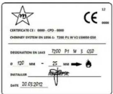
Fig. 3 - Example of label
9.4 HEIGHT-DEPRESSION
The depression (draught) of a chimney flue depends also on its height. Check the depression with the values provided at FEATURES page 35. Minimum height 3,5 meters.
9.5 MAINTENANCE
- The fumes extraction pipes (fumes conduit + chimney flue + chimney pot) must always be cleaned, scrubbed and checked by an expert stove-repairer, in compliance with current regulations, with the instructions of the stove-manufacturer and the directives of your insurance company.
• In case of doubts, please follow the most restrictive regulations. - Have your chimney flue and chimney pot checked and cleaned by an expert chimney sweep at least once a week. The chimney sweep has to release a written declaration about the security of the system.
• Not cleaning compromise safety.
9.6 CHIMNEY POT

1
2
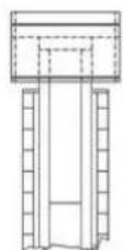
Fig. 4 - Anti-wind chimney pots
The chimney pot is important for the correct running of the heating appliance:
• We recommend using an anti-wind chimney pot, see Fig. 4 page 8.
- The hole width for fumes exhaust must be the double of the chimney flue width and fitted in a way that the fume exhaust is assured also in case of wind.
- It should prevent the infiltration of rain, snow and animals.
- The outlet height in the atmosphere must be away from the reflux area caused by the roof structure or by obstacles laying nearby (see Fig. 2 page 7).
9.7 CHIMNEY COMPONENTS

Fig. 5 - Chimney components
LEGEND Fig. 5 page 9
| 1 Chimney pot |
| 2 Fume outlet |
| 3 Chimney flue |
| 4 Termal insulation |
| 5 External wall |
| 6 Chimney union |
| 7 Fume pipe |
| 8 Heat generator |
| 9 Inspection door |
| 10 T-union with inspection plug |
9.8 EXTERNAL AIR INLET
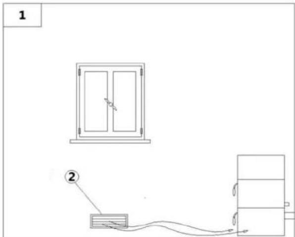
Fig. 6 - Direct air inflow
LEGEND Fig. 6 page 9
1 Room to ventilate
2 External air inlet
• The room must be endowed with an external air recycling for a good climate in your ambient.
- The air inflow from outside to the inner occurs directly, through an opening on the external wall of the room (see Fig. 6 page 9).
• Bedrooms, garages, and store of flammable materials are excluded.
- The air inlet should have a total net surface of 80 sqcm ^2 : the aforesaid surface is to widen if inside the room there are other activated appliances (for example: electric ventilators for foul air suction, cooker hoods, other stoves, etc...) which depress the environment.
- At switched on appliance it is necessary to check that the pressure fall between the room and the outside does not exceed 4.0 Pa value: if necessary widen the air inlet (EN 13384).
- The air inlet must be realized at a height close to the floor with an external grid against birds. In such a way it cannot be obstructed by any object.
- In case of installation with sealed-chamber the air inlet is not necessary.
9.9 COMBUSTIBLE AIR INLET FOR SEALED-CHAMBER INSTALLATION

flowchart
graph TD
    A["Room 1"] --> B["Zone ①"]
    B --> C["Zone ②"]
    C --> D["Zone ③"]
    D --> E["Zone ③"]
    E --> F["Zone ①"]
    style A fill:#f9f,stroke:#333
    style B fill:#ccf,stroke:#333
    style C fill:#cfc,stroke:#333
    style D fill:#fcc,stroke:#333
    style E fill:#cff,stroke:#333
    style F fill:#ffc,stroke:#333

Fig. 7 - Air inlet for sealed-chamber installation
LEGEND Fig. 7 page 10
| 1 ≥ 1,5 m t |
| 2 ≥ 0,3 m t |
| 3-3 Sectional view |
| 4 Shield grid |
| 5 Curve inlet to turn downwards |
Check FEATURES page 35 if the purchased stove has a sealed-chamber. If the stove is endowed with a sealed-chamber and you want also the whole installation with sealed chamber, please read the following instructions:
- It is necessary to extract the air for combustion directly from outside.
- Use a tube with minimum ∅60 mm and maximum 2 meters lenaht: to connect see the back of the stove.
- French standards require installation in double-walled flues (concentric system). The combustion air is drawn from the cavity.
- During installation step is necessary to verify the minimum distances required for the combustible air inlet as (for example) an open door or window causes a vortex which could remove the combustible air necessary to the stove (see the underlying scheme).
- On the external wall it is necessary to install a curve at 90° to protect the combustible air inflow from wind effects: turn the curve inlet downwards, see Fig. 7 page 10.
- Endow the curve with an external shield grid against birds in such a way that it cannot be obstructed by any object.

Check with your local authorities if exists any restrictive regulation regarding the combustible air inlet: if present, they must be applied

In some countries and/or regions the installation with sealed-chamber is obligatory: in case of doubt, please follow the most restrictive regulations.
How to connect to the stove in the sealed chamber with concentric system:

natural_image
Close-up of a red industrial device with ventilation grilles and a curved black line (no visible text or symbols)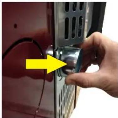
natural_image
Close-up of a hand adjusting a mechanical component with a yellow arrow pointing to the handle (no text or symbols visible)
natural_image
Close-up of a red vehicle's front panel with a white plastic hose and yellow arrow pointing to the cable (no text or symbols visible)Fig. 8 - Phase1 Fig. 9 - Phase 2 Fig. 10 - Phase 3
• Original position with completely embedded tube (see Fig. 8 page 11).
• Pull out the tube for 2 cm (see Fig. 9 page 11).
- Insert the female tube 6 cm (see Fig. 10 page 11).
9.10 CHIMNEY FLUE CONNECTION
Your pellet stove works through a fume draught forced by a fan. It is obligatory to check that all pipes are realized in compliance with the following regulation on material selection: EN 1856-1, EN 1856-2 e UNI/TS 11278. All must be effected by specialized personnel or companies as provided by UNI 10683:2012.
- The connection between the appliance and the chimney flue should be short in order to favor the draught and to avoid condensation in the pipes.
- The fume conduit should be equivalent or longer than the outlet joint ones (∅ 80 mm).
- Some stove models are endowed with a lateral and/or back exhaust. Check that the unused exhaust is sealed with the plug given with standard equipment.
| SYSTEM TYPE ∅80 mm PIPE ∅100 mm PIPE | ||
| Minimum vertical length 1,5 mt 2 mt | ||
| Maximum length (with 1 union) 6,5 mt 10 mt | ||
| Maximum length (with 3 unions) 4,5 mt 8 mt | ||
| Maximum number of unions 3 3 | ||
| Level section (minimum inclination 3%) 2 mt | 2 mt | |
| Installation at a height above 1200 m a.s.l. | NO | Obligatory |
- Use a plate pipe for stoves of ∅80 mm or ∅100 mm depending on the type of system and with silicone gaskets.
- It is forbidden to use metal, fibre cement or aluminium flexible pipes.
- For change of direction it is obligatory always to use a union (with angle >90^ ) with inspection plug which enables an easy periodic cleaning of the pipes.
- Please assure you that after the cleaning the inspection plugs are sealed with its efficient gasket.
- It is forbidden to connect more appliances to the same fume conduit.
- It is forbidden to convey in the same fume conduit exhausts from overhanging cooker hoods.
- It is forbidden to exhaust flue gases directly from the wall towards the outside and closed spaces also at open top.
- It is forbidden to connect any other appliance (wood stoves, cooker hoods, boilers, etc...).
- The fume conduit must be placed at a distance of minimum 500 mm from flammable or heat-susceptible components.
9.11 EXAMPLES OF CORRECT INSTALLATION

Fig. 11 - Example 1
LEGEND Fig. 11 page 12
| 1 Insulating material |
| 2 Reduction from ∅100 to ∅80 mm |
| 3 Inspection plug |
| 4 Minimum safety distance = 0,5 mt |
- Chimney flue installation ∅100/120 mm with an enlarged drilling for pipe transit.

Fig. 12 - Example 2
LEGEND Fig. 12 page 12
| 1 Insulating material |
| 2 Inspection plug |
| 3 Chimney inspection entrance |
| 4 Minimum safety distance = 0.5 mt |
| 5 Inclination ≥ 3° |
| 6 Level section ≤ 1 mt |
- Old chimney flue with an inserted pipe of minimum ∅100/120 mm and with an external door which enables the chimney cleaning.
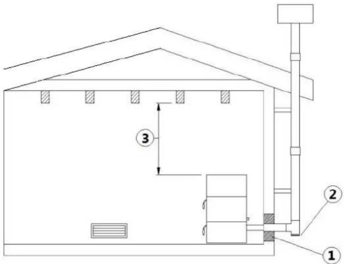
Fig. 13 - Example 3
LEGEND Fig. 13 page 13
| 1 Insulating material |
| 2 Inspection plug |
| 3 Minimum safety distance = 0,5 mt |
- External chimney flue entirely made up of insulated stainless steel pipes, i.e. with double wall of minimum ∅100/120 mm: all must be firmly attached to the wall. For chimney against wind effects please (see Fig. 4 page 8).
- Ducting system through T-unions which enables an easy cleaning without disassembling the pipes.

We recommend to check with your chimney flue manufacturer the safety distances which must be respected and the type of insulating material. The aforesaid regulations are valid also for holes made on the wall (EN 13501 - EN 13063 - EN 1856 - EN 1806 - EN 15827).
10 FUEL

10.1 FUEL
- Use top-quality pellets because they have influence in the calorific value and in ash remains.
- Pellets features are: dimension ∅6-7mm (D06 Class), maximum lenght 40 mm, calorific value 5kWh/kg, humidity ≤ 10%, ash remains ≤ 0.7%, they must be correctly pressed and not much mealy, without sizing agents, resins and other additives (it is advisable to use pellets in compliance with the regulation EN14961-2 type ENplus-A1).
- Not adequate pellets cause a bad combustion, a frequent burning pot obstruction and exhaust conduits obstruction. Further it decreases the calorific value, soils the glass and increases consumptions and ash and unburnt granules quantity.

Humid pellets cause a bad combustion and running, so please assure you that they are stored in dry places and far at least one meter from the stove and/or any other source of heat.
- It is advisable to try different type of pellets available on the market and to choose that which gives the best performance.
• The use of bad quality pellets can damage the stove so that the warranty and manufacturer liability fall. - On all our product are used high-quality materials such as stainless-steel, steel, cast iron, etc... These materials, before being sold on the market, are tested in laboratory, but despite this on the components which enable the pellets flow (auger) there could exist minimum differences in the material used, in roughness and porosity, which could generate usual variations in fuel transportation (pellets), causing a flame raising or drapping with a possible switching off at lower powers.
- Depending on the type of pellets it could be necessary a parameters adjustment, please contact an Authorized Assistance Service.
11 INSTALLATION

11.1 INTRODUCTION
- The assembly position must be chosen depending on environment, outlet, chimney flue.
- Check with local authorities if there are any restrictive regulations which regard the combustible air inlet, room ventilation, fume exhaust system together with chimney flue and chimney pot.
- Check if there is the combustible air inlet.
- Check the probable presence of other stoves or appliances which could depress the room.
- Check at switched on stove if there is the presence of CO in the room.
- Check if the chimney has the necessary draught.
- Check if during the fume passage all has been executed in safety (probable fume losses and distances from flammable materials, etc....).
- The installation of the appliance must enable an easy access for appliance, fume exhaust pipes and chimney flue cleaning.
• The installation must enable en easy access to the electric connection plug (see ELECTRIC CONNECTION page 17).
• To install more appliances, the external air inlet must be correctly dimensioned (see FEATURES page 35).
11.2 OVERALL DIMENSIONS

Fig. 14 - General dimensions
LEGEND Fig. 14 page 14
| 1 Hole combustion air inlet d.6 cm |
| 2 Exhaust fumes d.8 cm |
| 3 80,3 cm |
| 4 76,5 cm |
| 5 15,8 cm |
| 6 26,8 cm |
| 7 6,5 cm |
| 8 8,5 cm |
| 9 8,2 cm |
| 10 71 cm |
| 11 8,5 cm |
| 12 20,5 cm |
| 13 33 cm |
11.3 GENERAL INSTALLATION WITH PEDESTAL

Fig. 15 - General installation with pedestal
LEGEND Fig. 15 page 15
| 1 Stove | |
| 2 Minimum lateral distance = 300 mm | |
| 3 Minimum rear distance = 200 mm | |
| 4 Minimum front distance = 1000 mm | |
- It is obligatory to install the stove away from walls and/or pieces of furniture, with a minimum air flow of 300 mm on the sides and 200 mm on the back, to enable an efficient appliance cooling and a good distribution of heat in the room (see Fig. 15 page 15).
• If the walls are made up of flammable materials, check the safety distances (see Fig. 15 page 15). - At maximum power check that the wall temperature does not ever exceed 80°C. If it would be necessary please install a fire resistant plate on the concerned walls.
• In some countries also masonring load-bearing walls are considered flammable.
11.4 PEDESTAL ASSEMBLY

natural_image
Close-up of a hand adjusting a wall-mounted device panel, showing a button and ventilation slots (no text or symbols visible)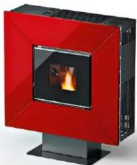
natural_image
Red and black electric stove with visible flame inside (no text or symbols)Fig. 16 - Assembling the pedestal Fig. 17 - Stove on the pedestal
- Lay the stove on the floor horizontally.
- Place pedestal and, using the Allen key provided, tighten the no.4 M6 screws under the pedestal (see Fig. 16 page 15).
- Put the stove upright (see Fig. 17 page 15).
11.5 WALL MOUNTING
The stove is suitable for wall mounting. The can be attached to a load-bearing wall in masonry (NOT plasterboard, wood, etc...) suitable for the entire weight of the stove.

Fig. 18 - Wall mounting
LEGEND Fig. 18 page 15
| 1 Stove |
| 2 Minimum lateral distance = 300 mm |
| 3 Minimum front distance = 1000 mm |
- It is obligatory to install the stove away from walls and/or pieces of furniture, with a minimum air flow of 300 mm on the sides to enable an efficient appliance cooling and a good distribution of heat in the room (see Fig. 18 page 15).
- For safety fire regulations the distances from flammable or sensible to heat objects (sofas, pieces of furniture, wooden covering, etc...) must be respected, has described in Fig. 18 page 15.
- If there are highly flammable objects (curtains, fitted carpet, etc...), all these distances must be further increased with 1 meter.

In some countries also masonring load-bearing walls are considered flammable.
If you want to fix the stove to a non-flammable material wall, you need to fix the support to the wall (the support is provided with the stove).
- Call an expert to prepare the fumes outlet hole and the combustion air inlet hole.
• To fix the rear support to the wall with metal plugs suitable for the weight of the stove (see Fig. 19 page 16).

Fig. 19 - Mounting on non-flammable wall
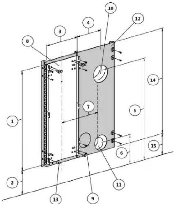
Fig. 20 - Mounting on flammable wall
LEGEND Fig. 19 page 16 - Fig. 20 page 16
| 1 695 mm |
| 2 179 mm |
| 3 260 mm |
| 4 202 mm |
| 5 710 mm |
| 6 206 mm |
| 7 332 mm |
| 8 Wall support |
| 9 Metal plugs |
| 10 Fumes outlet hole d.120 mm |
| 11 Combustion air inlet hole d.80 mm |
| 12 Spacer (cod. 5013016) |
| 13 M8x20 bolt |
| 14 735 mm |
| 15 159 mm |
If the stove is to be fixed to an inflammable wall, it is compulsory to attach further support to the wall cod. 5013016 (the support is NOT provided with the stove).
- Call an expert to prepare the fumes outlet hole and the combustion air inlet hole.
• To fix the rear support to the wall with metal plugs suitable for the weight of the stove (see Fig. 20 page 16).
11.6 ELECTRIC CONNECTION


Warning: the appliance must be installed by an authorized technician!
- The electric connection occurs through a cable with plug put in an electric socket which is able to support charge and tension specific of every model, as described in the technical datas table (see FEATURES page 35).
- The plug must be easily accessible when the appliance is installed.
- Please further assure you that your network is endowed with an efficient earth connection: if it does not exist or if it is not efficient, please endow you with one in compliance with the law.
- Connect the supply cable first on the back of the stove (see Fig. 21 page 17) and then at a wall electric socket.

natural_image
Close-up of an electrical control panel with a glowing orange indicator and power outlet (no visible text or symbols)Fig. 21 - Electric socket with master switch
- The master switch O/I (see Fig. 21 page 17) is to open only to switch the stove on, otherwise it is advisable to keep it off.
- Do not use extension cables.
- If the feeder cable is damaged, it must be replaced by an authorized technician.
- When the stove is not going to be used for a long period of time, it advisable to remove the plug from the socket on the wall.
11.7 CONNECTION TO THE EXTERNAL THERMOSTAT

The stove works through a thermostat probe placed in its inner. If you desire, the stove can be connected to an external room thermostat. This operation must be executed by an authorized technician.
- External thermostat: "SET TEMP ROOM" a temperature which is round 7°C.
- External chronothermostat: "SET TEMP ROOM" a temperature which is round 7°C and desable the chrono functions from the menu 03-01 "CHRONO ENABLE" ("OFF").
11.8 VENTILATION

• The stove is endowed with a ventilation system.
- The air blown from fans keeps the appliance at a low temperature range in order to avoid high stresses to the materials which make it up.
- Do not cover the hot air outlet slits with any object to avoid stove's overheating!
- The stove is not suitable for food cooking.

natural_image
Black and red photo of a cooking pot on a slatted stove with crossed red lines (no text or symbols)Fig. 22 - Do not cover air slits
12 USE

12.1 INTRODUCTION
To have the best performance with the lowest consumption please follow the here described instructions.
• The lightning of the pellets occurs very easily if the installation is correct and if the chimney flue is efficient.
- Switch on the stove at Power 1 for at least 2 hours in order to enable the materials which make up the boiler and the fireplace to adjust the inner springing stress.
- By using the stove the varnish inside the combustion chamber could be subjected to alterations. This occurrence can be attributed to different reasons: an excessive stove overheating, the presence of chemical agents in bad quality pellets, bad chimney draught, etc. Therefore varnish endurance in the combustion chamber cannot be guarantee.

Oily plant waste and lacquers can cause smells and smoke during the first working hours: it is advisable to ventilate the room because they could be noxious to people and animals.

Set values from 1 to 5 are defined by the manufacturer and they can be changed only by an authorized technician.
12.2 CONTROL PANEL
| PANEL ELEMENT DESCRIPTION | |
 | P1 and P2: when in set temperature mode, they are useful to increase or decrease the thermostat value from min. 6°C to max 40°C. Keeping pressed P2 key it is possible to see the fume temperature at the exhaust. Both have programming functions. |
 | P3: it enables to enter set temperature and User and Technician parameters menu. |
 | P4: switching on and off, alarm reset and exit from programming. |
 | P5 and P6: increase and decrease the calorific power from 1 to 5. |
 | Chrono: active time programming. |
 | Ignition plug: active ignition. |
 | Auger: active. |
 | Fume fan: active. |
 | Exchanger fan: active. |
 | - |
 | Alarm: active. |

Fig. 23 - LCD control display
LEGEND Fig. 23 page 19
| 1 Time | |
| 2 Power | |
| 3 State | |
| 4 Message | |
| 5 Temperature |
12.3 USER MENU
By once pressing P3 key you can hace access to user parameter controlling. To let them slide press P5 and P6 keys. They are:
| POS. REFERENCE DESCRIPTION | ||
| 1 SET CLOCK | Set date and time. The board is provided with a lithium battery which enables a clo autonomy of 3/5 years. SeeCLOCK SETTING page 21. | |
| 2 SET CHRONO | Press once P3: "CHRONO ENABLE" appears. Press P3 again and with P1 and P2 put in "OFF" or "ON". For daily, week-end or weekly programming, seeDAILY PROGRAMMING page 21.CAUTION: do not active if STAND-BY function is active! | |
| 3 | SELECT LANGUAGE | Press once P3 key and with P1 and P2 keys select the desired language. |
| 4 STAND-BY MODE | It activates a function which, if the set ambient temperature has been exceeded for more then 10 minutes, start the switching off phase up. If the ambient temperature has fall more than 2°C, the stove will restart automatically up, starting fromSTART UP page 20. Press once P3 key and with P1 and P2 keys put in "OFF" or "ON". CAUTION: do not activate if CHRONO function is active! | |
| 5 | BUZZER MODE(audio alarm) | Press once P3 key and with P1 and P2 keys put in "OFF" or "ON". |
| 6 INITIAL LOAD | When the stove has its first ignition, the auger is completely empty. If it should be necessary do a precharge by pressing P3 key, then P1 key for starting up and P4 key for stop. | |
| 7 STOVE STATE | It shows all parameters connected to the stove state: this is a menu for the Authorized Technician | |
| 8 TECHNICA SETTING Only for the Authorized Technician. | ||
| 9 FLAME SETTING It enables to set the flame dipending on the draught of the chimney flue. | ||
12.4 START UP
We remind you that the first ignition must be carried out by a specialized and authorized technician who will check that all is installed in compliance with current regulations and checks the efficiency.
- If inside the combustion chamber there are booklets, manuals, etc..., remove them.
- Check if the door is correctly closed.
- Check if the stove is correctly inserted in the electric socket.
• Before switching the stove on, assure you the burning pot is clean. - To start the stove up, keep pressed P4 key for an instant till it will be shown "START" and "PREHEAT WAIT": the preheating of the ignition resistance starts. After 2 minutes about, it will be shown "PELLET LOAD, WAITING FIRE", in this phase the auger loads the pellet and the heating of the resistance continues. When the temperature is sufficiently high (after 7-10 minutes about), the ignition is considered as happened and on the display shows "FIRE PRESENT".
- Completed the phase "FIRE PRESENT", the control unit enter the "WORK" phase showing the set calorific power and ambient temperature. It is in this phase that P5 and P6 keys settle the stove power from 1 to 5. If the value of the ambient temperature exceeds the limit set on the keyboard on the temperature setting, the calorific power will be carried at the minimum showing "WORK, MODULAT". When the ambient temperature turns back below the set temperatur, the stove turns back to the set power.
12.5 STOVE ADJUSTMENT

The stove is adjusted according to the chimney flue and used pellets datas, as per technical characteristics (see FEATURES page 35). If the datas do not correspond, the authorized technician can adjust the stove.
- If the pellet is small in size and with a greater calorific power, (for example: encrusted burning pot), the pellet drop must be decreased from the menu "FLAME SETTING", press P3 "PELLET TYPE", press P3 again "PELLET LOAD" and with P2 key decrease the pellet quantity from -1 (which is -2%) till -9 (which is -18%).
- If the chimney flue has a lower draught (for example: weak flame, sooty glass) the revolutions of the geared motor must be increased from the menu "FLAME SETTING", press P5 "CHIMNEY TYPE", press P3 "FUME-EXH CHIMNEY" and with P1 key increase the fume fan revolutions from +1 (which is +5%) till +9 (which is +30%).
- If the chimney flue has a greater draught (for example: because of pellets fall on the burning pot) decrease the fume fan revolutions from -1 to -9.

Pay attention if the value is positive or negative..
12.6 FAILED IGNITION
If the pellets do not burn, the failed ignition will be indicated by the alarm "FAILED IGNITION".
- If the room temperature is lower than 10^ C, the plug is not able to bear the ignition stage. To support it please insert some pellets in the burning pot and a piece of burning firelighter igniter material on the pellets (for example firelighters cubes).
- Too much pellets in the burning pot, or humid pellet, or sooty burning pot make ignition difficult and create dense white smoke which is harmful to health and can cause explosions on the combustion chamber. It is therefore necessary not to stand in front of the stove during ignition stage if dense white smoke is present.

If after some months the flame appears weak and/or orange colored or the glass tends to blackens and the burning pot to become encrusted, clean the stove, clean the fume conduit and the chimney flue.
12.7 POWER FAILURE
• After a black-out lower than 5 seconds, the stove turns back to the power which was settled.
- After a black-out of more than 5 seconds, the stove enters the "COOLING WAIT" phase. Completed this phase, it starts automatically up with the different phases (see START UP page 20).
12.8 TEMPERATURE SETTING
- To modify the ambient temperature it is sufficient to press P1 and P2 keys according to the desired temperature inside the menu "SET TEMP ROOM".
• To see the set temperature, press once P1 key.
12.9 FUME TEMPERATURE
To check the fume temperature at the exhaust it is sufficient to keep pressed P2 key.
12.10 SWITCHING OFF
To switch the stove off, keep pressed P4 key: the display shows "FINAL CLEANING". After about 10 minutes, also the fume fan switches off (this happens always, independently if the stove is hot or cold). Then "OFF" will be shown.
12.11 CLOCK SETTING
- Press P3 key and then P5 key till underlining "SET CLOCK" menu (02).
- Press once P3 (DAY) and with P1 and P2 keys select the day of the week (Monday, Tuesday, Wednesday, Thursday, Friday, Saturday, Sunday).
- Press for the second time P3 key (HOURS) and with P1 and P2 keys set the hour.
- Press for the third time P3 key (MINUTES) and with P1 and P2 keys select the minutes. Press for the fourth time P3 key (DAY) and with P1 and P2 keys select the day of the month (1,2,3...29,30,31).
- Press for the fifth time P3 key (MONTH) and with P1 and P2 keys select the month:
- Press for the sixth time P3 key (YEAR) and with P1 and P2 keys select the year.
- To exit from the programme press P4 twice.
12.12 DAILY PROGRAMMING
It allows to enable, disable and settle the daily chronothermostat functions.
Press P3 key and then P5 key till the menu "SET CHRONO". Press once P3 key and with P5 and P6 keys select the "PROGRAM DAY". Press once P3 till finding "CHRONO DAY". With P1 and P2 keys put in "OFF" or "ON". It is possible to set two working times delimited by the set times.
After "CHRONO DAY":
- Press P5: the display shows "START 1", with P1 and P2 keys set the ignition time value or put in "OFF".
- Press P5: the display shows "STOP 1", with P1 and P2 keys set the switching off time value or put in "OFF".
- Press P5: the display shows "START 2", with P1 and P2 keys set the ignition time value or put in "OFF".
- Press P5: the display shows "STOP 2", with P1 and P2 keys set the switching off time value or put in "OFF".
- Press P4 key three times to exit from the menu.
12.13 WEEKEND PROGRAMMING
It allows to enable, disable and settle the chronothermostat functions during saturday and sunday.
Press P3 key and then P5 key till the menu "SET CHRONO". Press once P3 key and with P5 and P6 keys select "PROGRAM WEEKEND". Press once P3 till finding "CHRONO WEEKEND". With P1 and P2 keys put in "OFF" or "ON". It is possible to set two working times delimited by the set times and valid only for saturday and sunday. After "CHRONO WEEKEND":
- Press P5: the display shows "START 1 WEEKEND", with P1 and P2 keys set the ignition time value or put in "OFF".
- Press P5: the display shows "STOP 1 WEEKEND", with P1 and P2 keys set the switching off time value or put in "OFF".
- Press P5: the display shows "START 2 WEEKEND", with P1 and P2 keys set the ignition time value or put in "OFF".
- Press P5: the display shows "STOP 2 WEEKEND", with P1 and P2 keys set the switching off time value or put in "OFF".
- Press P4 key three times to exit from the menu.
12.14 WEEKLY PROGRAMMING
It allows to enable, disable and settle the weekly hermostat functions (saturday and sunday included).
Press P3 key and then P5 key till the menu "SET CHRONO". Press once P3 key and with P5 and P6 keys select "PROGRAM WEEK". Press once P3 till finding "WEEKLY CHRONO". With P1 and P2 keys put in "OFF" or "ON". It is possible to set four working times delimited by the set times.
After "WEEKLY CHRONO":
Press P5: the display shows "START PROG-1", with P1 and P2 keys insert the ignition time value or put in "OFF".
Press P5: the display shows "STOP PROG-1", with P1 and P2 insert the switching off value or put in "OFF".
- Press P5: the display shows "MONDAY PROG-1", with P1 and P2 keys set "ON" or "OFF".
- Press P5: the display shows "TUESDAY PROG-1", with P1 and P2 keys set "ON" or "OFF".
- Press P5: the display shows "WEDNESDA PROG-1", with P1 and P2 keys set "ON" or "OFF".
- Press P5: the display shows "THURSDAY PROG-1", with P1 and P2 keys set "ON" or "OFF".
- Press P5: the display shows "FRIDAY PROG-1", with P1 and P2 keys set "ON" or "OFF".
-
Press P5: the display shows "SATURDAY PROG-1", with P1 and P2 keys set "ON" or "OFF".
-
Press P5: the display shows "SUNDAY PROG-1", with P1 and P2 keys set "ON" or "OFF".
- Now press P5 and repeat all the previous instructions for Prog-2, Prog-3, Prog-4.
• To exit press three times P4.
12.15 PELLET SUPPLY


Fig. 24 - Wrong opening of the pellets bag Fig. 25 - Right opening of the pellets bag
It is necessary to avoid to fill the hopper with the pellet when the stove is running.
- Do not get the bag of pellet in contact with hot stove surfaces.
- Do not empty the hopper with remaining fuels (unburnt pellet) from the burning pot coming from ignition waster.
12.16 REMOTE CONTROL
- The stove can be operated through a remote control.
• Operation requires 1 CR 2025 Lithium battery.

Used batteries contain metals which are harmful for the environment; they must therefore be disposed of separately in the special containers.
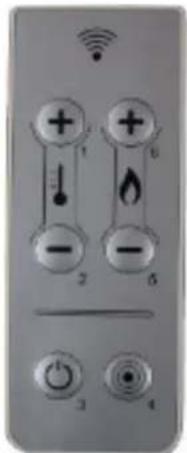
Fig. 26 - Remote control
LEGEND Fig. 26 page 22
| Button 1 Increase the desired temperature |
| Button 2 Decrease the desired temperature |
| Button 3 On / off |
| Button 4 Menu |
| Button 5 Decrease the power level from 5 to 1 |
| Button 6 Increase the power level from 1 to 5 |
13 SAFETY SYSTEM

13.1 INTRODUCTION
Safety devices are used to prevent and avoid the risk of damages to people, animales and objects. It is forbidden to execute repearing by no authorized personnel otherwise the warranty and the manufacturer liability fall.
13.2 "BLACK OUT" ALARM
"ACTIVE ALARM" "AL 1 - BLACK OUT": current breaking during ignition.
- Reset the error with P4 key. The stove carries out the phase "FINAL CLEANING" and then is in "OFF":
- Clean the burning pot and start the stove up again with P4 key.
13.3 "EXHAUST PROBE" ALARM
To the exhaust is connected a probe which contantly controls the temperature during working time. "ACTIVE ALARM" "AL 2 - EXHAUST PROBE": the probe is damaged or disconnected.
- Reset the error with P4 key. The stove carries out the phase "FINAL CLEANING" and the is in "OFF".
- Check the type of glitch as ALARMS page 29.
- Clean the burning pot and start the stove up again with P4 key.
13.4 "HOT EXHAUST" ALARM
If the fume probe registers a temperature at the exhaust higher then 180^ C, the display shows "HOT EXHAUST". Then the combustible (pellet) drop will be decreased at phase 1.
This function has the aim to bring the values within preset values. If for any reason the temperature would not decrease but increase, at 215°C the display shows "ACTIVE ALARM" "AL 3 - HOT EXHAUST" and the stove start the switching off phase up.
- Reset the error with P4 key. The stove carries out the phase "FINAL CLEANING" and the is in "OFF".
- Check the type of glitch as ALARMS page 29.
- Clean the burning pot and start the stove up again with P4 key.
13.5 "FAN FAILURE" ALARM
"ACTIVE ALARM" "AL 4 - FAN FAILURE": the fume fan is out of order.
- Reset the error with P4 key. The stove carries out the phase "FINAL CLEANING" and the is in "OFF".
- Check the type of glitch as ALARMS page 29.
- Clean the burning pot and start the stove up again with P4 key.
13.6 "FAILED IGNITION" ALARM
"ACTIVE ALARM" "AL 5 - FAILED IGNITION": the temperature is not sufficient for ignition.
- Reset the error with P4 key. The stove carries out the phase "FINAL CLEANING" and the is in "OFF".
- Check the type of glitch as ALARMS page 29.
- Clean the burning pot and start the stove up again with P4 key.
13.7 "NO PELLET" ALARM
If the fume probe registers a temperature at the exhaust lower than the minimum threshold and the display shows "ACTIVE ALARM" "AL 6 - NO PELLET".
- Reset the error with P4 key. The stove carries out the phase "FINAL CLEANING" and the is in "OFF".
• Full the hopper. - Clean the burning pot and start the stove up again with P4 key.
13.8 "THERMAL SAFETY" ALARM
In the hopper is installed a automatic thermostat which activates if the temperature excursion exceeds the allowed limits, so avoiding the possibility that the pellet inside the hopper could burn because of overheating. "ACTIVE ALARM" "AL 7 - THERMAL SAFETY": the thermostat stops the power supply to the auger.
- Reset the error with P4 key. The stove carries out the phase "FINAL CLEANING" and then is in "OFF".
- Check the type of glitch as ALARMS page 29.
- Clean the burning pot and start the stove up again with P4 key.
13.9 "FAILURE DEPRESS" ALARM
To the boiler is connected a pressostat which control the depression and in some stove models on the fire door id installed a microswitch which registers the opening.
"ACTIVE ALARM" "AL 8 - FAILURE DEPRESS": the pressostat and/or fire door which is not correctly closed stops the power supply to the auger.
- Reset the error with P4 key. The stove carries out the phase "FINAL CLEANING" and then is in "OFF".
- Check the type of glitch as ALARMS page 29.
- Clean the burning pot and start the stove up again with P4 key.
14 MAINTEINANCE

14.1 INTRODUCTION
For a long working life of the stove, have a periodic cleaning of the stove as described in the following paragraphs.
- Fume outlet pipes (fume conduit + chimney flue + chimney pot) must always be cleaned, scrubbed and checked by an authorized technician in compliance with local regulations, with the instructions of the manufacturer and those of your insurance company.
- If there are no local regulations and no instruction from your insurance company, it is necessary to have your fume pipe, chimney flue and chimney pot cleaned at least once a year.
- It is also necessary to have the combustion chamber, motors and fans cleaned and to have the gaskets and the electronical elements checked at least once a year.

All these operations must be planned in time with your Autorized Technical Assistance Service.
• After a long ineffective time, before turning on the stove check if there are obstructions in the fume exhaust.
- If the stove had been using continuously and intensely, the whole system (chimney included), must be cleaned and checked more frequently.
• In case of replacement of damaged pieces please ask for the original spare part at the Autorized Retailer.
14.2 BURNING POT AND ASH TRAY CLEANING

The burning pot and ash tray cleaning must be executed at least every 2 days.
- Open the door.

natural_image
Close-up of a hand using a tool to cut or clean a metallic object, no visible text or symbols
natural_image
Hand inserting a small mechanical component into a machine (no visible text or symbols)
natural_image
Close-up of hands using a tool to apply material to a dark, metallic component (no visible text or symbols)Fig. 27 - Burning pot extraction Fig. 28 - Ash tray extraction Fig. 29 - Burning pot cleaning
- Extract the burning pot (see Fig. 27 page 24) from its seat and empty it from the ash.
• Extract the ash tray (see Fig. 28 page 24) and empty it from the ash. - If necessary clean with a pointed object the holes obstructed by encrustations (see Fig. 29 page 24).

natural_image
Close-up of a metallic mechanical component with a dark cylindrical rod inserted into a rectangular opening (no visible text or symbols)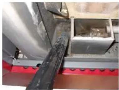
natural_image
Close-up of a mechanical assembly with a black rod inserted into a metallic housing (no visible text or symbols)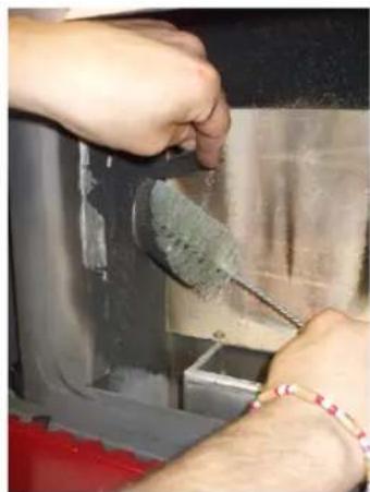
natural_image
Close-up of hands using a tool to clean or store items inside a container (no visible text or symbols)Fig. 30 - Burning pot box cleaning Fig. 31 - Ash tray box cleaning Fig. 32 - Cleaning with a brush
- Clean and drain away the burning pot box and ash tray box from ash which has accumulated in its inner (see
Fig. 30 page 24 and Fig. 31 page 24).
- Clean also the hole for pellet drop with a brush (see Fig. 32 page 24).
- The ash remains must be poured in a metal container with a sealed lid and this container must never get in touch with combustible materials (for example put on a wooden floor), as the inner ash keeps the embers firing for a long time.
- Only when the embers are off the ash coul be poured in the organic waste.
- Pay attention if the flame becomes red colored, if it is weak or if black smoke creates in the inner: in this case the burning pot is encrusted and needs to be cleaned. If it is broken, it must be replaced.
14.3 HOPPER AND AUGER CLEANING

Per each pellets supply, check the probable presence of meal, sawdust and other remainns on the hopper bottom. If present, they must be removed with the aid of a vacuum cleaner (see Fig. 33 page 25).

natural_image
Close-up of a metal grid with visible grain and dust, no text or symbols presentFig. 33 - Hopper and auger cleaning

The hand rejector grid must not ever be removed from its housing. Clean the hopper bottom and the visible part of the auger exclusively as shown in the picture (see Fig. 33 page 25).
14.4 FUME CHAMBER CLEANING

Every 4/8 weeks the fume chamber cleaning must be executed.
For CLOE model: remove top panel and then right panel.
For SQUARE model: loosen the 2 screws that lock front right panel and remove it.

natural_image
Close-up of hands adjusting a white plastic hose inside a white industrial machine (no visible text or symbols)
natural_image
Close-up of a metal pipe joint with visible wear and a circular hole, no text or symbols presentFig. 34 - Fume chamber Fig. 35 - Fume chamber cleaning
- Unscrew the 2 fume chamber closing zincate panel screw (see Fig. 34 page 25).
- Clean with a vacuum cleaner the ash which has accumulated on the inner (see Fig. 35 page 25).
- After the cleaning the opposite operation is to repeat checking the gasket efficiency and integrity: if necessary provide for its replacement by an Authorized Technician.
14.5 FUME CONDUIT CLEANING

The exhaust system must be cleaned every month.

natural_image
Close-up of a brown textured surface next to a black cylindrical object, with no visible text or symbols.- Remove the inspection lid of the T-union (see Fig. 36 page 26).
- Extract the ash which has accumulated in the inner.
- After cleaning repeat the operation in reverse order, checking the condition and efficiency of the gasket, and if necessary replace it.

Is it important to hermetically seal the cap to avoid harmful fumes escaping into the room.
14.6 FUME FAN CLEANING

Clean every the year the fume fan from ash or dust which can cause a blade unbalance and a greater noise.

As this operation is so delicate it must therefore be executed by an Authorized Technician.

natural_image
Close-up of a mechanical component with a metallic housing and screw holes, partially enclosed by a fan grille (no visible text or symbols)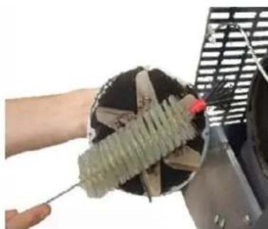
natural_image
Close-up of a hand using a tool to lift a green electrical insulator inside a black fan (no text or symbols visible)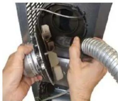
natural_image
Close-up of hands installing or adjusting a mechanical component with coiled tubing (no visible text or symbols)Fig. 37 - Fume fan cleaning: phase1 Fig. 38 - Phase 2 Fig. 39 - Phase 3
• Follow the process as describer in Fig. 37 page 26, Fig. 38 page 26 and Fig. 39 page 26.
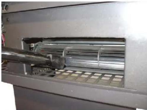
14.7 ROOM FAN CLEANING

Clean every the year the room fan from ash or dust which can cause a blade unbalance and a greater noise.

As this operation is so delicate it must therefore be executed by an Authorized Technician.
natural_image
Close-up of a metallic industrial machine with internal pipes and a metal rod inserted (no visible text or symbols)- Remove the lower panel and clean with a vacuum cleaner the ash and the dust which has accumulated on the inner (see Fig. 40 page 27).
14.8 FUME PASSAGES CLEANING

Clean the fume passages every year.

natural_image
Close-up of hands installing or adjusting a black air vent on a red appliance (no visible text or symbols)
natural_image
Close-up of a hand inserting a yellow tool into a black plastic component (no visible text or symbols)Fig. 41 - Remove upper grid Fig. 42 - Remove top cover
- Remove upper grid (see Fig. 41 page 27).
- Loosen the screws of top cover (see Fig. 42 page 27).

natural_image
Interior view of a metal shelving unit with a broom and handle (no visible text or symbols)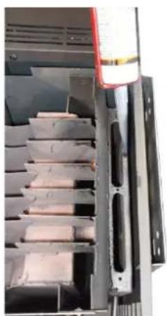
natural_image
Interior view of a storage or processing unit with stacked rectangular compartments and a red warning light (no visible text or symbols)Fig. 43 - Fume passages cleaning Fig. 44 - Silicon laying
- Clean the fume passages with the aid of a brush (see Fig. 43 page 27).
- Lay the silicon round the hole (see Fig. 44 page 27) and screw again the lids.
- Reassemble all.
14.9 FUME PIPES ANNUAL CLEANING

Clean once a week from soot with brushes.
The cleaning operation must be executed by a specialized stove-repairer who will provide for the cleaning of fume pipe, chimney flue and chimney pot. He will also check their efficiency and will release a written declaration
of the safety of the appliance. This operation must be executed at least once a year.
14.10 GENERAL CLEANING

For cleaning external and inner parts of the stove do not use steel wools, muriatic acid or other corrosive and abrasive materials.
14.11 CLEANING OF PAINTED METAL PANELS

To clean painted metal panels use a soft cloth. Do not use degreasant agents like alcool, diluents, acetone, gasoline because these could irremediably damage the varnish.
14.12 CLEANING OF CERAMIC AND STONE PANELS

Some stove models has an external lining made up of ceramic or stone. These pieces are handmade therefore they could inevitably present crazings, seedinesses, shadings. To clean ceramic or stone panels use a soft and dry cloth. If using any cleaners this will seep through the crazings putting them in evidence.
14.13 GASKET REPLACEMENT

In case of deterioration of fire door, hopper or fume chamber gaskets, it is necessary to replace them by an autorized technician in order to guarantee the good running of the stove.

Use exclusively original spare parts.
14.14 GLASS CLEANING

The glass-ceramic of the fire door is able to stand till 700°C but not to thermal shocks. The probable cleaning with usual sale product for glass cleaning must be effected at cool glass in order to avoid explosions.

You should clean the fire door glass every day!
15 IN CASE OF ANOMALY

15.1 ALARMS

Before of every intervention of the Authorized Technician, the same Technician has the duty to check that the parameters of the mother board correspond with those of the table you own.

In case of doubts regarding the use of the stove, please call ALWAYS the Authorized Technician in order to avoid irreparable damages!
| ALARM CAUSE SOLUTION INTERVENTION | |||
| AL 1 - BLACK OUT | Power cut during ignition phase. | Clean the burning pot and switch the stove on again. |  |
| AL 2 - EXHAUST PROBE | Disconnected fume temperature probe | Have the stove checked. |  |
| Faulty fume temperature probe | Replace the fume probe. |  | |
| AL 3 - HOT EXHAUST | Faulty fume probe Replace the fume probe. |  | |
| Faulty mother board Replace the electronic board. |  | ||
| The exchanger fan does not work | Replace the ambient fan. |  | |
| Too high pellet drop value | Adjust the pellet loading. |  | |
| AL 4 - FAN FAILURE | Faulty protection fuse of the fume fan | Replace the fuse (1,25A). |  |
| Faulty fume fan | The pellets can burn also thanks to the chimney flue depression and without the aid of the fume fan. Have the fume fan replaced immediately. It can be noxious to health to let the stove running without fume fan. |  | |
| ALARM CAUSE SOLUTION INTERVENTION | |||
| AL 5 - FAILED IGNITION | Empty hopper Fill the hopper. |  | |
| The burning pot has not been cleaned | Clean the burning pot. |  | |
| The ignition threshold has not been reached | Clean the burning pot and switch the stove on again. |  | |
| Faulty ignition plug Replace the ignitor resistance. |  | ||
| Too sever external temperature | Start the stove up again. |  | |
| Humid pellet The pellets must be stored in a dry place. Please check it. |  | ||
| Blocked thermal probe Replace the thermal probe. |  | ||
| Faulty mother board Replace the mother board. |  | ||
| AL 6 - NO PELLET | Empty hopper Full the hopper. |  | |
| AL 7 - THERMAL SAFETY | Boiler overheating | Let the stove cooling. (If the problem persists please call an Authorized Technician). |  |
| The ambient exchanger fan does not work | Replace the ambient fan. |  | |
| Temporary power cut | The lack of tension during the running implies the overheating of the boiler and the intervention of the automatic thermostat. Let the stove cooling and start the stove up again. |  | |
| Faulty automatic thermostat | Replace the automatic thermostat. |  | |
| Faulty mother board Replace the mother board. |  | ||
| ALARM CAUSE SOLUTION INTERVENTION | |||
| AL 8 - FAILURE DEPRESS | Obstructed exhaust | The exhaust chimney is partially or totally obstructed. Call en expert stove-repairer who executes a check from the exhaust up to the chimney pot. |  |
| Fume fan out of order | The pellet can burn also thanks to the chimney flue depression without the aid of the fan. Have the fume fan immediately replaced. It can be noxious to health to let the stove running without fan. |  | |
| Obstructed connecting nozzle | Clean the connecting nozzle. |  | |
| Faulty pressostat Replace the pressostat. |  | ||
| Faulty electronic board Replace the mother board. |  | ||
| Extreme chimney lenght | Contact an expert stove repairer and check that the exhaust chimney is in compliance with regulations: see CHIMNEY FLUE page 6. |  | |
| Advers whether conditions | In case of strong wind there can be a negative pressure to the chimney. Check and switch the stove on again. |  | |
| The fire door is not correctly closed | Close the fire door correctly and check if the gaskets are broken. |  | |
| Fire door microswitch faulty or out of order | Replace the fire door microswitch. |  | |
15.2 PROBLEM SOLVING

Before of every Authorized Technician intervention, the same Technician has the duty to check if the parameters of the mother board correspond to those of the table you own.

In case of doubts regarding the use of the stove, please contact ALWAYS the Authorized Technician on order to avoi irreparable damages!
| PROBLEM CAUSE SOLUTION INTERVENTION | |||
| The control display does not switch on | The stove is without power supply | Check if the plug is connected. |  |
| Burned protection fuse in the electric socket | Replace the protection fuses in the electric socket (3.15A-250V). |  | |
| Faulty control display | Replace the control display. |  | |
| Faulty flat cable Replace the flat cable. |  | ||
| Faulty electronic board | Replace the mother board. |  | |
| Pellets do not reach the combustion chamber | Empty hopper Full the hopper. |  | |
| Auger blocked by a foreign object (for example nails) | Clean the auger. |  | |
| The auger geared motor is out of order | Replace the geared motor. |  | |
| Check if on the display there is an "ACTIVE ALARM" | Have the stove checked. |  | |
| The fire extinguish and the stove stops | Empty hopper Full the hopper. |  | |
| Auger blocked by a foreign object (for example nails) | Clean the auger. |  | |
| Bad quality pellets Try other types of pellets. |  | ||
| Pellet drop value too low "phase 1" | Adjust the pellet loading. |  | |
| Check if on the display there is an "ACTIVE ALARM" | Have the stove checked. |  | |
| Stove running and display showing "BURN POT CLEAN" | Automatica burning pot cleaning | The stove is at minimum, fume fan at maximum. NO PROBLEM! |  |
| PROBLEM CAUSE SOLUTION INTERVENTION | |||
| Flames are weak and orange coloured, pellets do not burn properly and the glass blackens | Not sufficient combustion air | Check as following: probable obstructions of the combustible air inlet from the back or from the bottom of the stove; burning pot obstructed holes with too ash remains. Have the fan blades and auger cleaned. |  |
| Obstructed exhaust | The exhaust chimney is partially or totally obsturcted. Contact an expert stove-repairer who checks the stove from the exhaust up to the chimney pot. Provide immediately for stove cleaning. |  | |
| Obstructed stove Pro | Provide immediately at the inner cleaning of the stove. |  | |
| The fume fan is out of order | The pellets can burn also thanks to chimney flue depression without the aid of the fume fan. Have the fume fan immediately replaced. It can be noxious to health to let the stove running without fume fan. |  | |
| The exchanger fan continues to turn even though the stove has just cooled | Faulty fume temperature probe | Replace the fume probe. |  |
| Faulty mother board | Replace the mother board. |  | |
| Ash remains along the stove | Faulty or out of order door gaskets | Replace the gaskets. |  |
| Not sealed fume pipes | Contact an expert stove-repairer who will immediately provide for sealing the junctions with high-temperature silicone and/or for replacing pipes with those in compliance to current regulations. A not sealed fume channelisation can be noxious to health. |  | |
| Stove running and display showing "WORK, MODULAT" | Reached ambient temperature | The stove runs at minimum. NO PROBLEM! |  |
| Stove running and display showing "HOT EXHAUST" | Reached fume outlet limit temperature | The stove runs at minimum. NO PROBLEM! |  |
| Stove running and display showing "SERVICE" | Routine maintenance alert (it does not block the system) | When this flashing message appears upon start-up, it means that the preset operating hours have elapsed before maintenance. Contact the service centre. |  |
16 TECHNICAL DATAS

16.1 REPAIR INFORMATION
Now we give some instructions for the Authorized Technician to take into consideration to have access to stove mechanical components.
- For fuse replacement in the electric socket which lies on the back of the stove, extract the fuses to change with the aid of a screwdriver in the shutter (see Fig. 45 page 34).

natural_image
Close-up of an electrical control panel with a highlighted orange button and yellow circle (no visible text or symbols)Fig. 45 - Shutter with the fuse to remove
Proceed as follows:
- Remove all panels.
- After these operations you can have access at the following components: geared motor, ignition plug, ambient fan, fume fan, ambient probe, fume probe, thermostat, electronic board, pressostat.
- For cleaning or replacement of the auger it is necessary to unscrew the three bolt of the geared motor and to extract it, unscrew the two screws lying under the geared motor of the auger, remove the hand rejector inside the hopper and then unscrew the inner bolt of the auger.
• To assembly proceed at the contrary.
16.2 FEATURES
| DESCRIPTION CLOE - CLOE | ^3 6,5 kW SQUARE 6,5 kW | |
| WIDTH 82 cm 82 cm | ||
| DEPTH 28,5 cm 27 cm | ||
| HEIGHT with pedestal 91,5 cm 92 cm | ||
| WEIGHT with pedestal 92-98-107 kg 92-98 kg | ||
| INTRODUCED THERMIC POWER (Min/Max) 2,7 - 7,2 kW | 2,7 - 7,2 kW | |
| NOMINAL THERMIC POWER (Min/Max) 2,5 - 6,5 kW 2,5 - 6,5 kW | ||
| EFICIENCY (Min/Max) 93 - 89,5 % 93 - 89,5 % | ||
| FUME TEMPERATURE (Min/Max) 85 - 172 °C 85 - 172 °C | ||
| FUME MAXIMUM LOADING CAPACITY (Min/Max) | 2,4 - 4,4 g/s | 2,4 - 4,4 g/s |
| CO EMISSIONS (13% O_2 ) (Min/Max) | 0,050 - 0,008 % | 0,050 - 0,008 % |
| OGC EMISSIONS (13% O_2 ) | 0,4 mg/Nm ^3 | 0,4 mg/Nm ^3 |
| NOx EMISSIONS (13% O_2 ) | 110 mg/Nm ^3 | 110 mg/Nm ^3 |
| Medium CO CONTENTS at 13% O_2 (Min/Max) | 628 - 103 mg/Nm ^3 | 628 - 103 mg/Nm ^3 |
| Medium POWDER CONTENTS at 13% O_2 (Max) | 16 mg/Nm ^3 | 16 mg/Nm ^3 |
| CHIMNEY DEPRESSION (Max) 11 Pa | 11 Pa | |
| MINIMUM SAFETY DISTANCE from flammable materials | 30 cm 30 cm | |
| ON SHARED CHIMNEY FLUE NO | NO | |
| FUME OUTLET DIAMETER | ∅80 mm | ∅80 mm |
| COMBUSTIBLE | Pellet ∅6-7 mm | Pellet ∅6-7 mm |
| PELETS HEATING VALUE | 5 kWh/kg | 5 kWh/kg |
| PELETS HUMIDITY | ≤ 10% | ≤ 10% |
| HEATING VOLUME 18/20°C Coeff. 0,045 kW (Min/Max) | 60 - 156 m ^3 | 60 - 156 m ^3 |
| HOURLY CONSUMPTION (Min/Max) | 0,50 - 1,50 kg/h | 0,50 - 1,50 kg/h |
| HOPPER CAPACITY | 8 kg | 8 kg |
| RANGE (Min/Max) | 16 - 5,3 h | 16 - 5,3 h |
| SUPPLY | 230 V - 50 Hz 230 V - 50 Hz | |
| POWER INPUT (Max) | 350 W | 350 W |
| INGNITER RESISTANCE POWER INPUT | 300 W | 300 W |
| MINIMUM EXTERNAL AIR INLET (last effective area) | 80 cm ^2 | 80 cm ^2 |
| STOVE WITH SEALED CHAMBER | YES | YES |
| EXTERNAL AIR INLET FOR SEALED CHAMBER | ∅60 mm | ∅60 mm |
PELLET STOVES · WOOD STOVES · WOOD COOKING STOVES THERMOSTOVES · PELLET FIREPLACE INSERTS
CADEL srl
FREEPOINT by Cadel
Via Foresto Sud, 7
31025 Santa Lucia di Piave (TV) - ITALY
tel. +39.0438.738669
fax +39.0438.73343
www.cadelsrl.com
- Summary
- MANUAL SIMBOLOGY
- DEAR CUSTOMER
- CAUTIONS
- 4
- SAFETY REQUIREMENTS
- WARRANTY CONDITIONS
- EN
- 6
- SPARE PARTS
- 7
- WARNINGS FOR THE CORRECT DISPOSAL OF THE PRODUCT
- 8
- PACKAGING AND HANDLING
- PACKAGING
- STOVE HANDLING
- 9
- CHIMNEY FLUE
- INTRODUCTION
- CHIMNEY FLUE
- TECHNICAL FEATURES
- HEIGHT-DEPRESSION
- MAINTENANCE
- CHIMNEY POT
- CHIMNEY COMPONENTS
- EXTERNAL AIR INLET
- LEGEND Fig. 6 page 9
- COMBUSTIBLE AIR INLET FOR SEALED-CHAMBER INSTALLATION
- CHIMNEY FLUE CONNECTION
- EXAMPLES OF CORRECT INSTALLATION
- FUEL
- FUEL
- INSTALLATION
- INTRODUCTION
- OVERALL DIMENSIONS
- GENERAL INSTALLATION WITH PEDESTAL
- PEDESTAL ASSEMBLY
- WALL MOUNTING
- ELECTRIC CONNECTION
- CONNECTION TO THE EXTERNAL THERMOSTAT
- VENTILATION
- USE
- INTRODUCTION
- CONTROL PANEL
- USER MENU
- START UP
- STOVE ADJUSTMENT
- FAILED IGNITION
- POWER FAILURE
- TEMPERATURE SETTING
- FUME TEMPERATURE
- SWITCHING OFF
- CLOCK SETTING
- DAILY PROGRAMMING
- WEEKEND PROGRAMMING
- WEEKLY PROGRAMMING
- PELLET SUPPLY
- REMOTE CONTROL
- SAFETY SYSTEM
- INTRODUCTION
- "BLACK OUT" ALARM
- "EXHAUST PROBE" ALARM
- "HOT EXHAUST" ALARM
- "FAN FAILURE" ALARM
- "FAILED IGNITION" ALARM
- "NO PELLET" ALARM
- "THERMAL SAFETY" ALARM
- "FAILURE DEPRESS" ALARM
- MAINTEINANCE
- INTRODUCTION
- BURNING POT AND ASH TRAY CLEANING
- Fig. 30 page 24 and Fig. 31 page 24).
- HOPPER AND AUGER CLEANING
- FUME CHAMBER CLEANING
- FUME CONDUIT CLEANING
- FUME FAN CLEANING
- ROOM FAN CLEANING
- FUME PASSAGES CLEANING
- FUME PIPES ANNUAL CLEANING
- GENERAL CLEANING
- CLEANING OF PAINTED METAL PANELS
- CLEANING OF CERAMIC AND STONE PANELS
- GASKET REPLACEMENT
- GLASS CLEANING
- IN CASE OF ANOMALY
- ALARMS
- PROBLEM SOLVING
- TECHNICAL DATAS
- REPAIR INFORMATION
- PELLET STOVES · WOOD STOVES · WOOD COOKING STOVES THERMOSTOVES · PELLET FIREPLACE INSERTS
Brand : Cadel
Model : Square
Category : Heating