DSM4 - Network switch OSD Audio - Free user manual and instructions
Find the device manual for free DSM4 OSD Audio in PDF.


| Product Type | Network Switch |
| Model | DSM4 |
| Brand | OSD Audio |
| Number of Ports | 4 |
| Port Type | 10/100 Mbps Fast Ethernet |
| Management | Unmanaged |
| Power Supply | External DC adapter (5V, 1A) |
| Dimensions (W x D x H) | 5.0 x 3.0 x 1.0 in (12.7 x 7.6 x 2.5 cm) |
| Weight | 0.5 lbs (0.23 kg) |
| LED Indicators | Power, Link/Activity per port |
| Operating Temperature | 32°F to 104°F (0°C to 40°C) |
| Storage Temperature | -4°F to 158°F (-20°C to 70°C) |
| Humidity | 10% to 90% non-condensing |
| Mounting | Desktop or wall-mountable |
| Standards | IEEE 802.3, 802.3u |
| Data Transfer Rate | 10/100 Mbps |
| MAC Address Table | 1K entries |
| Switching Capacity | 0.8 Gbps |
| Fanless Design | Yes (silent operation) |
| Housing Material | Metal |
| Cleaning Instructions | Wipe with dry cloth; do not use liquids |
| Safety Certifications | FCC, CE |
Frequently Asked Questions - DSM4 OSD Audio
User questions about DSM4 OSD Audio
0 question about this device. Answer the ones you know or ask your own.
Ask a new question about this device
Download the instructions for your Network switch in PDF format for free! Find your manual DSM4 - OSD Audio and take your electronic device back in hand. On this page are published all the documents necessary for the use of your device. DSM4 by OSD Audio.
USER MANUAL DSM4 OSD Audio
Thank you for giving OSD AUDIO the chance to win your business! We are confident you will find that OSD offers an outstanding combination of performance and value in everything we make. To ensure you get the most out of your new amplifier, please take a moment to read this manual before you get started.
Features
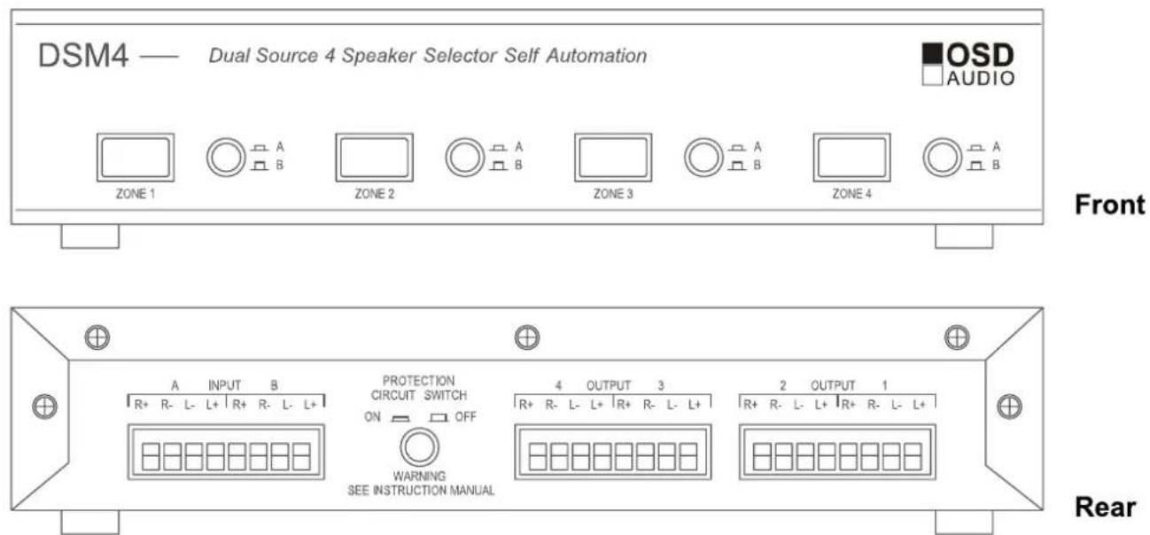
The OSD DSM4, DSM6 and DSM8 are low-profile speaker selector boxes that allow you to distribute a stereo high-level (amplified) signal into multiple zones. These models include a manually activated impedance protection circuit that can be turned ON to prevent the impedance presented to your receiver from dropping below an unsafe level of 5 Ohms, regardless of the number and impedance ratings of your speakers. The protecting switch can also be turned off when used as part of a planned system of impedance matching volume controls, allowing you to get the most out of your amplifier. If you are unsure, consult a professional contractor.
DSM switchers have the ability to select between "A" and "B" sources. Above is an 4-position plug on the left rear of the unit which is labeled "A B". This is where the speaker level inputs from the two sources ("A" and "B") are connected. Attach the wires in the same manner as the speaker wires connect to the outputs of the DSM unit (see below).
Connecting your OSD Speaker Selector
The terminals on the rear of the speaker selector will accommodate 14 gauge cable which will suffice for even long connections (greater than 100 feet of wire). For shorter distances, 16- or 18-gauge wire will suffice. For behind-the-wall installations, we recommend using UL Class 3 approved cable (marked "CL3") for compliance with local building codes. When connecting a speaker and amplifier, it is important to retain the correct polarity. To do this, be sure that the wire attached to the +, red, or positive terminal on the speaker connects to the +, red, or positive terminal on the rear of the selector box. Similarly, the -, black, or negative terminal on the speaker must connect to the respective -, black, or negative terminal on the selector box. Polarity should also be maintained when connecting your amplifiers
outputs to the amplifier inputs on the selector box.
Connecting Speaker Cables
- Route the speaker cables from the amplifier and from each speaker zone to the speaker selecto
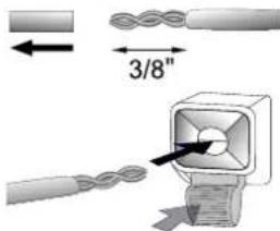
- Strip 3/8" insulation from the end of the cable and twist the exposed end to avoid fraying.
- Press on a "push-pin" terminal to reveal an eye into which the twisted cable is inserted; release the terminal to lock
| Specifications | |||
| DSM4 | DSM6 | DSM8 | |
| Listening Zones | 4 | 6 | 8 |
| A/B source input | A/B source input | A/B source input | |
| Protection Circuit High Power Resistors | 2 x 10 ohm/15 watt per channel | 2 x 10 ohm/15 watt per channel | 3 x 10 ohm/15 watt per channel |
| Power Handling with Protection Circuit ON | 70 watts/channel | 70 watts/channel | 100 watts/channel |
| Power Handling with Protection Circuit OFF | 140 watts/channel | 140 watts/channel | 200 watts/channel |
| Dimensions: H x W x D | 216 x 112 x 49 mm8.5" x 4.4" x 1.93" | 433 x 112 x 49 mm17" x 4.4" x 1.93" | 433 x 112 x 49 mm17" x 4.4" x 1.93" |
Never place a speaker selector where it is exposed to excessive moisture or heat. Leave at least 1" of space above the unit for heat dissipation.
Brand : OSD Audio
Model : DSM4
Category : Network switch