
RT-930AX - Audio tuner ROTEL - Free user manual and instructions
Find the device manual for free RT-930AX ROTEL in PDF.


| Product Type | Audio Tuner |
| Brand | Rotel |
| Model | RT-930AX |
| Dimensions (WxHxD) | 430 x 82 x 315 mm |
| Weight | Approximately 5.0 kg |
| Power Supply | AC 120V / 230V, 50/60 Hz |
| Power Consumption | 15 W |
| Tuning Range | FM 87.5–108 MHz, AM 530–1600 kHz |
| FM Sensitivity | 1.5 µV (IHF) |
| FM Signal-to-Noise Ratio | 75 dB (mono) |
| FM Alternate Channel Selectivity | ≥60 dB |
| Output Level | 0.5 Vrms (fixed) |
| Antenna Inputs | FM: 75 ohms (coaxial), AM: loop antenna |
| Presets | 30 FM / 30 AM (total 60) |
| Display | Digital frequency and preset number |
| Remote Control | Not included |
| Audio Outputs | RCA (L/R) |
| Power Output for Accessories | None |
| Cleaning Instructions | Use a soft, dry cloth; avoid solvents |
| Safety | Do not expose to moisture; unplug during cleaning |
| Spare Parts Availability | Contact Rotel authorized service centers |
| Repairability | Designed for professional service; internal adjustments require qualified personnel |
Frequently Asked Questions - RT-930AX ROTEL
User questions about RT-930AX ROTEL
0 question about this device. Answer the ones you know or ask your own.
Ask a new question about this device
Download the instructions for your Audio tuner in PDF format for free! Find your manual RT-930AX - ROTEL and take your electronic device back in hand. On this page are published all the documents necessary for the use of your device. RT-930AX by ROTEL.
USER MANUAL RT-930AX ROTEL
TO PREVENT FIRE OR SHOCK HAZARD,
DO NOT EXPOSE THIS APPLIANCE TO
RAIN OR MOISTURE.
Write your SERIAL NUMBER here.
The number is located near the name
plate on the rear panel.
SAFETY INSTRUCTION
- Read Instructions— All the safety and operating instructions should be read before the appliance is operated.
- Retain Instructions—The safety and operating instructions should be retained for future reference.
- Heed Warnings—All warnings on the appliance and in the operating instructions should be adhered to.
- Follow Instructions—All operating and use instructions should be followed.
- Water and Moisture—The appliance should not be used near water—for example, near a bathtub, washbowl kitchen sink, laundry tub, in a wet basement, or near a swimming pool, and the like.
- Carts and Stands—the appliance should be used only with a cart or stand that is recommended by the manufacturer.
6A. An appliance and cart combination should be moved with care. Quick stops, excessive force, and uneven surfaces may cause the appliance and cart combination to overturn. - Wall or Ceiling Mounting— The appliance should be mounted to a wall or ceiling only as recommended by the manufacturer.
- Ventilation—The appliance should be situated so that its location or position does not interfere with its proper ventilation. For example, the appliance should not be situated on a bed, sofa, rug, or similar surface that may block the ventilation openings; or placed in a built-in installation such as a bookcase or cabinet that may impede the flow of air through the ventilation openings.
- Heat— The appliance should be situated away from heat sources such as radiators, heat registers, stoves, or other appliances (including amplifiers) that produce heat.
- Power Sources—The appliance should be connected to a power supply only of the type described in the operating instructions or as marked on the appliance.
- Grounding or Polarization—The precautions that should be taken so that the grounding or polarization means of an appliance is not defeated.
- Power-Cord Protection—Power-supply cords should be routed so that they are not likely to be walked on or pinched by items placed upon or against them, paying particular attention to cords at plugs, convenience receptacles, and the point where they exit from the appliance.
Power Lines – An outdoor antenna should be located away from power lines.
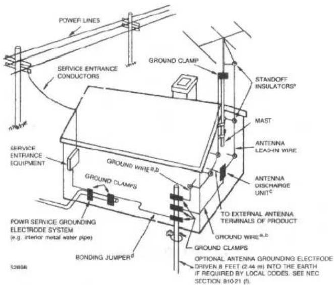
Outdoor Antenna Grounding – If an outside antenna is connected to the receiver, be sure the antenna system is grounded so as to provide some protection against voltage surges and built up static charges. Section 810 of the National Electrical Code, ANSI / NFPA No. 70–1984, provides information with respect to proper grounding of the mast and supporting structure, grounding of the lead-in wire to an antenna discharge unit, size of grounding conductors, location of antenna-discharge unit, connection to grounding electrodes, and requirements for the grounding electrode. See Figure.
a- Use No. 10 AWG (5.3 mm ^2 ) copper, No. 8 AWG (8.4 mm ^2 ) aluminum, No. 17 AWG (1.0 mm ^2 ) copper-clad steel or bronze wire, or larger, as a ground wire.
b- Secure antenna lead-in and ground wires to house with stand-off insulators spaced from 4-6 feet (1.22 - 1.83 m) apart.
c- Mount antenna discharge unit as close as possible to where lead-in enters house.
d- Use jumper wire not smaller than No. 6 AWG (13.3 mm ^2 ) copper, or the equivalent, when a separate antenna-grounding electrode is used.
PORTABLE CART
WARNING

natural_image
Symbolic illustration of a person climbing a ladder inside a circle (no text or symbols)- Cleaning— The appliance should be cleaned only as recommended by the manufacturer.
- Nonuse Periods—The power cord of the appliance should be unplugged from the outlet when left unused for a long period of time.
- Object and Liquid Entry— Care should be taken so that objects do not fall and liquids are not spilled into the enclosure through openings.
- Damage Requiring Service— The appliance should be serviced by qualified factory authorized service personnel when:
A. The power-supply cord or the plug has been damaged; or
B. Objects have fallen, or liquid has been spilled into the appliance; or
C. The appliance has been exposed to rain; or
D. The appliance does not appear to operate normally or exhibits a marked change in performance; or
E. The appliance has been dropped, or the enclosure damaged.
17. Servicing—The user should not attempt to service the appliance beyond that described in the operating instructions. All other servicing should be referred to qualified factory authorized service personnel.
WARNING: To reduce the risk of fire or electric shock, do not expose this appliance to rain or moisture
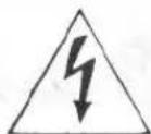
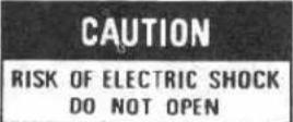

CAUTION: TO REDUCE THE RISK OF ELECTRIC SHOCK, DO NOT REMOVE COVER (OR BACK). NO USER-SERVICEABLE PARTS INSIDE. REFER SERVICING TO QUALIFIED SERVICE PERSONNEL.
The lightning flash with arrowhead symbol, within an equilateral triangle, is intended to alert the user to the presence of uninsulated "dangerous voltage" within the product's enclosure that may be of sufficient magnitude to constitute a risk of electric shock to persons.

The exclamation point within an equilateral triangle is intended to alert the user to the presence of important operating and maintenance (servicing) instructions in the literature accompanying the appliance.

EXAMPLE OF ANTENNA GROUNDING AS PER NATIONAL ELECTRICAL CODE INSTRUCTIONS
FOR U.S.A. ONLY
A WORD FROM ROTEL
Rotel take this opportunity to thank you for choosing our equipment for your home entertainment.
Rotel equipment represents a very high state of the art in sound reproduction, as the result of our everlasting determination to achieve the truly hi-fi performance. Please enjoy the sound Rotel have created for many years to come.
To make sure you get the most out of your equipment, please read this owner's manual carefully before you attempt any connections.
BEFORE CONNECTIONS
1. Place for Installation
Ensure to place the unit in a flat surface where it in free from humidity, vibration, high temperature and not exposed to direct sunlight. Also, be careful not to place the unit in a highly enclosed area without adequate ventilation around the unit. Do not block the ventilation openings at the top and the bottom of the unit to prevent excessive heat built up.
2. Electrical Requirements
Your equipment has been designed to be powered by the local AC voltage. Check the setting of your unit by looking at the rear panel name plate. Never try to plug the unit into an outlet of higher voltage, as this causes a serious fire hazard. Consult your dealer if in doubt.
3. Connecting the Power Cord
Always handle the Power cord with care. Ensure to connect the cord to the household wall outlet. When plugging and unplugging make sure the power switch on the unit is turned off.
4. Do not Open the Cabinet
There are no user-serviceable parts inside the cabinet of the unit. Do not attempt to open the cabinet or tamper with
EXCLUSIVE NOTE FOR U.K.
If your unit comes with a 2-core mains lead without a plug, neither core is to be connected to the earth terminal of a three pin plug, make certain that they are connected, according to the following instruction, to the proper terminals. Check that the terminals are screwed down firmly and no loose strands of wire are present.
IMPORTANT: The wires in this mains lead are coloured in accordance with the following code:
BLUE: NEUTRAL
BROWN: LIVE
As the colours of the wires in the mains lead of this apparatus may not correspond with the coloured markings identifying the terminals in your plug proceed as follows:
The wire which is coloured BLUE must be connected to the terminal which is marked with the letter N or coloured BLUE or BLACK. The wire which is coloured BROWN must be connected to the terminal which is marked with the letter L or coloured BROWN or RED. the internal components. If water or foreign object falls inside the unit by accident, disconnect the power cord immediately and consult a qualified electrician or your dealer.
5. Cleaning Your Unit
If your unit becomes dirty, wipe it gently with a soft, dry cloth. Never use solvents of any kind.
CONNECTIONS
- Connecting to Integrated Amplifier or Preamplifier
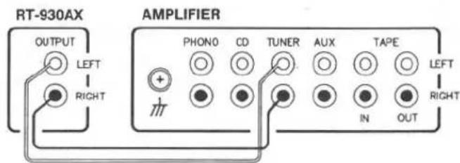
a) Connect the OUTPUT terminals on the back of the tuner to the TUNER inputs on the rear of your integrated amplifier or preamplifier using the proper interconnecting cords supplied with the tuner. Make sure the Right (RED) and the Left (WHITE) channels are correctly connected.
b) Note you may connect the tuner to the AUX inputs on your integrated amplifier or preamplifier, if necessary.
2. Installing and Connecting Antenna
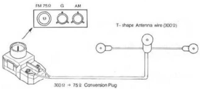
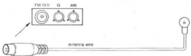
a) Indoor FM Antenna – The attached indoor antenna wire will suffice for proper, quiet broadcast reception in most good reception areas. To install it, connect the antenna to the FM Antenna terminals (75 ohm) on the back of the tuner. Then, stretch the wire out and secure along a wall or where signal reception is optimal.
- Indoor T-shap Antenna wire (Applicable for U.S.A., Canada or where approved to the usage)
- Indoor Antenna wire (Applicable for European version)
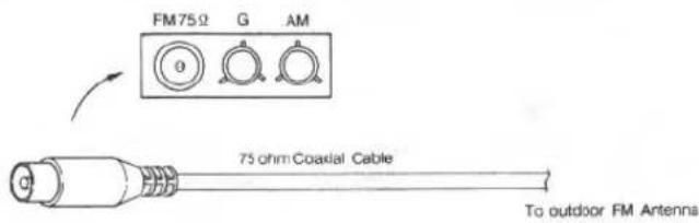
b) Outdoor FM Antenna – In areas of average to weak reception conditions, an outdoor antenna mounted on the roof or top of the building may be necessary for best results. When using such outdoor type antenna, ensure remove the indoor antenna. A 75-ohm coaxial cable is usually recommended. If using this type cable, properly hook it up to the designated antenna terminals on the back of the tuner.
When in doubt on the FM outdoor antenna system, consult your dealer.
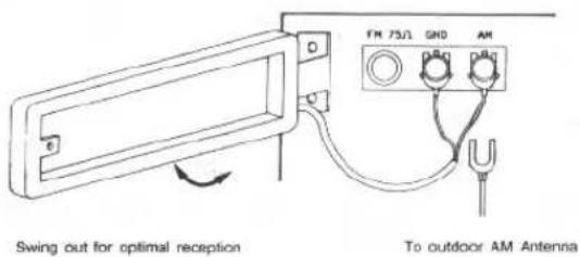
c) AM Antenna – The loop antenna is provided for AM reception. Lock the loop onto the loop holder on the back of the tuner, and connect the two ends to the antenna terminals marked G and AM. Swing out the loop around for finding the best AM reception. In difficult reception areas, connect an outdoor antenna which is usually a long piece of shielded wire to the AM terminal. Make sure the loop is still left connected even if the outdoor or another antenna is used.
SWITCHES AND CONTROLS
(1) Power Button
Press this button to turn on and off the unit.
CAUTION: As long as the power cord is connected to a live AC outlet, power is supplied to the tuner regardless of the position of the power button. This is to enable the memory backup to work.
(2) Power Indicator
Glows when power is turned on with the power button.
(3) Frequency Display and Multi-function Indicator
1) The frequency of the station selected is displayed. The band chosen, FM or AM, is also shown together with MHz for FM or KHz for AM (both MW and LW) on the frequency display.
2) The word AUTO lights up when the Auto Tuning is activated.
3) The word MEMORY lights up while the Memory button is activated.
4) The word STEREO glows when stereo broadcasting station is tuned in and when the Muting Off/Mono button
is deactivated for the stereo operation. It will also not light up for very weak stereo signals which the tuner will not receive in stereo.
5) The center TUNED indicator lights up when a station is properly tuned.
6) The channel (CH) indicator shows the numerical position of the preset station selected.
(4) Station Buttons
Pressing one of these buttons will tune the tuner to the frequency stored in the memory. Pressing the Memory button followed by one of these buttons will store the frequency displayed in that memory. It is possible to store up to 20 AM or FM stations in the memory. The Channel indicator in the display will show the number of the preset button selected.
CAUTION: If the AC power is removed from the tuner for more than 3 days, the frequencies stored in the memories will be lost.
NOTE: Each time you switch the tuner on, it will tune to the station frequency to which it was previously tuned.
(5) Memory Button
Stores frequencies in the tuner's memory. To store a frequency first tune to the desired broadcast program using the Tuning button. Then press the Memory button followed by one of the station buttons marked 1 to 10 and 11 to 20 with +10 button. Although there are only 10 buttons marked for positions 1 to 10, the +10 button converts the buttons to positions 11 to 20. So the buttons have double functions, e.g., the button 1 is also,11 when used with the +10 button.
The Memory indicator in the display will light up during this process. Note that once the Memory button is pressed, you must press the required station button within a few seconds to store the station frequency. If the Memory indicator is no longer light, you must press the Memory button again before storing the required frequency.
For example, to store desired local station in the station button 12, first tune in to the station, press the Memory button, then press and hold the +10 button while pressing the station button 2.
(6) + 10 Button
The tuner can store up to 20 different frequencies in its memory. The first 10 are selected (or stored) just by pressing the appropriate button. The second 10, numbers 11 to 20, are selected by pressing and holding the +10 button while pressing the station button simultaneously. Consider the +10 button like the shift button for capital letters on a typewriter.
(7) Mute Off/ Mono Button
Allows select of FM mono or stereo operation. When the Mono position is chosen, any broadcast will be received monaurally and the muting switch for suppressing interstation noise will be deactivated to pull weak signals which are normally cut off during the stereo operation. For reception of weak and noisy signals, use the Mute Off/Mono position. For normal use, choose the stereo operation by deactivating the Button. in this position, stereo broadcasts will be provided in stereo and the STEREO indicator will light up. When mono programs are broadcasted, mono sound is provided and the STEREO indicator will not light.
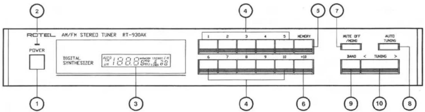
(8) Auto Tuning Button
Permits choose auto or manual tuning. In the auto mode, pressing either end of the Tuning button will cause the tuner to increase or decrease frequency until a reasonably strong signal is received. At this point the tuning will stop automatically.
In this mode, the AUTO indicator will light up. In the manual mode, pressing either end of Tuning button causes the tuner to increase or decrease the received frequency only for as long as the Button is depressed.
NOTE: Auto tuning does not operate for LW band.
(9) Band Button
Allows select reception on FM or AM (MW or LW in case of the tuner with both MW and LW).
(10) Tuning Button
Allows to tune in frequencies. Press the right side marked > to increase the frequency and the left side marked < to decrease it.
WORDS ON OPERATIONS
Precautions
- Before commencing operation, check to see if all connections are properly made.
- Always ensure to set the Volume control of the connected integrated amplifier or preamplifier to the minimum position before turning on the Power switch. Raise the volume level after the desired station is tuned in.
Memory Backup
As explained above, the memory for the preset stations is retained as long as the power cord is plugged into an AC outlet, regardless of the position of the Power button. However, if you leave the power cord unplugged for over three days, or if there is a power failure for over three days, the stored frequencies will be lost.
In such cases, the operation for storing frequencies in the memory have to be done again from the beginning.
Tuning Modes
Bear in mind that there are 3 modes of tuning with the tuner: auto tuning, manual tuning, and preset (memory) tuning. The simplest is the pereset tuning, as you only have to stored up to 20 of your favorite FM or AM stations once and recall any one of them with one touch (or two touches simultaneously in case of the buttons 11 to 20). Make sure to learn the proper method for the storage in the memory as instructed above.
HUM AND NOISE
In any high fidelity installations, hum may be caused by the interconnection of turntable, tuner, amplifier and speakers as the result of wiring, different grounding or locations of components.
Normally, hum is rarely associated with a faulty tuner, and the most likely cause lies in the installation. If any part of the antenna is in contact with a ground point (copper water pipes for example) hum will almost certainly result if your amplifier has a three core mains lead. It is also important to check that the audio interconnect cords have been pushes fully into their sockets on both tuner and amplifier. Sometimes the problem is actually caused by a signal which is too strong, in which case an antenna attenuator is recommended. If in doubt, please consult your dealer.
SPECIFICATIONS RT930-AX
FM TUNER SECTION
Usable Sensitivity.....12.5 dBf/ 1.2 uV (75 ohms)
50 dB Quieting Sensitivity:
Mono....11 dBf/ 2 uV (75 ohms)
Stereo....34.5 dBf/ 30 uV (75 ohms)
Signal to Noise Ratio (at 65 dBf):
Mono....75 dB
Stereo....70 dB
Harmonic Distortion (at 65 dBf):
1 kHz....0.08 % (mono), 0.3 % (stereo)
Frequency Response.....30 to 15,000 Hz, +/-1.5 dB
Capture Ratio......1.5 dB
Alternate Channel Selectivity:
(+/-400 kHz)....63 dB
Spurious Response Ratio.....95 dB
Image Response Ratio.....65 dB
IF Response Ratio......90 dB
AM Suppresion Ratio.....60 dB
Stereo Separation:
100 Hz/ 1 kHz/ 10 kHz...35 dB/ 40 dB/ 30 dB
Subcarrier Product Ratio.....60 dB
SCA Rejection Ratio.....70 dB
Output Level.....720 mV
Antenna Input....75 ohms unbalanced
AM TUNER SECTION MW LW
| Sensistivity......350 uV/ m | 750 uV/ m |
| Selectivity......27 dB | 25 dB |
| Signal to Noise Ratio......60 dB | 60 dB |
| Image Response Ratio......40 dB | 40 dB |
| If Response Ratio......40 dB | 40 dB |
Antenna....Loop Antenna
MISCELLANEOUS
Power Requirement.....120 V/ 60 Hz, 220 V/ 50 Hz,
240 V/ 50 Hz (depending on
destinations)
Power Consumption.....10 watts
Dimension (overall).....440 (W) x 72 (H) x 257 (D) mm
17-3/8"×2-7/8"×10-1/8"
Weight (net)....3.2 Kg / 7.04 lbs
- Specifications and design subject to possible modification without notice.
- SAFETY INSTRUCTION
- A WORD FROM ROTEL
- BEFORE CONNECTIONS
- Place for Installation
- Electrical Requirements
- Connecting the Power Cord
- Do not Open the Cabinet
- EXCLUSIVE NOTE FOR U.K.
- BLUE: NEUTRAL
- BROWN: LIVE
- Cleaning Your Unit
- CONNECTIONS
- Installing and Connecting Antenna
- SWITCHES AND CONTROLS
- Power Button
- Power Indicator
- Frequency Display and Multi-function Indicator
- Station Buttons
- Memory Button
- + 10 Button
- Mute Off/ Mono Button
- Auto Tuning Button
- Band Button
- Tuning Button
- WORDS ON OPERATIONS
- Precautions
- Memory Backup
- Tuning Modes
- HUM AND NOISE
- SPECIFICATIONS RT930-AX
- FM TUNER SECTION
- MISCELLANEOUS
Brand : ROTEL
Model : RT-930AX
Category : Audio tuner