
SX500.2 - Car radio KICKER - Free user manual and instructions
Find the device manual for free SX500.2 KICKER in PDF.


| Product Type | Car Stereo Amplifier |
| Model | SX500.2 |
| Brand | Kicker |
| Number of Channels | 2 |
| RMS Power (4 ohms) | 125W x 2 |
| RMS Power (2 ohms) | 250W x 2 |
| Bridged Power (4 ohms) | 500W x 1 |
| Frequency Response | 20Hz - 20kHz |
| Input Sensitivity | 200mV - 4V |
| Signal-to-Noise Ratio | >100 dB |
| Total Harmonic Distortion | <0.05% |
| Fuse Rating | 30A |
| Dimensions (W x H x L) | 7.5 in x 2.1 in x 10.2 in |
| Weight | 4.5 lbs |
| Power Supply | 12V DC (10-16V) |
| Protection Features | Thermal, short circuit, over-voltage |
| Recommended Speaker Impedance | 4 ohms (stereo), 4 ohms (bridged) |
| Filter Type | Variable low-pass (50-250 Hz) |
| User Manual Available | Yes, free PDF download |
| Warranty | 1 year (manufacturer) |
Frequently Asked Questions - SX500.2 KICKER
User questions about SX500.2 KICKER
0 question about this device. Answer the ones you know or ask your own.
Ask a new question about this device
Download the instructions for your Car radio in PDF format for free! Find your manual SX500.2 - KICKER and take your electronic device back in hand. On this page are published all the documents necessary for the use of your device. SX500.2 by KICKER.
USER MANUAL SX500.2 KICKER
WITH DIGITAL SIGNAL PROCESSING
©2003 STILLWATER DESIGNS • P.O. BOX 459 • STILLWATER, OK 74076 USA • 405.624.8510 • WWW.KICKER.COM
OWNER'S MANUAL
SX900.2, SX600.2, SX500.2, SX400.2
STEREO AMPLIFIERS
KICKER®
SX .2 Series
Amplifier
Owners Manual
Two channel Models: SX400.2 / SX500.2 / SX600.2 / SX900.2
Attention:
Please take a moment and record the information asked for below in the provided area. It is also a good idea to attach the original sales receipt or a copy of it to this page for future reference
If for any reason you require service on this amplifier during the warranty period, you will need to provide this information and a copy of the receipt to Kicker to validate your warranty.
ALWAYS KEEP YOUR RECEIPT!
Congratulations!
You have just purchased the latest in amplifier technology to carry the famous KICKER name. Your KICKER SX series amplifier employs the latest in DSP signal processing to give you total control over your sound. Like all KICKER products it is designed and built to give you years of powerful and trouble-free performance. This installation manual contains valuable information on how to get the most out of your new SX series amplifier.
Thanks for buying KICKER. Enjoy!
Dealer Where Purchased:
Purchase Date:
Amplifier Model Number:
Amplifier Serial Number:
5X P 20000000000000
Features
Low Impedance Operation Stable Into 2 ohm stereo
or 4 ohm mono loads
SORT Protection Circuitry (short circuit, Over-voltage, Reverse polarity, Thermal) Protects amplifier from accidents and out of spec operation.
MOSFET Power Supply Provides high efficiency operation.
PAST (Pre Amp Signal Transfer) Output RCA jacks to pass the incoming signal to another amplifier or component.
SAMS (Stereo And Mono Simultaneously) Amplifier will operate into a bridged mono load and a stereo load at the same time.
Low Pass Filter Fully adjustable digital crossover with variable slope and crossover frequency. 30 Hz - 20 kHz in 1/12 octave spacing. OFF - 36 dB per octave slope in 6 dB increments.
High Pass Filter Fully adjustable digital crossover with variable slope and crossover frequency. 10 Hz - 16 kHz in 1/12 octave spacing. OFF - 36 dB per octave slope in 6 dB increments.
Kicking Fully adjustable single band digital parametric equalizer with variable Q (bandwidth), variable center frequency and variable boost or cut. Q range 5 - 10 in .5 steps. Center frequency 20 kHz - 20 kHz in 1/12 octave steps. Boost or cut range +/- 18 dB
Adjustable Phase The output phase of each channel can be set at 0 Degrees or 180 Degrees. Left and Right channels can be linked or independently adjusted
Ultramatch Gain Structure Digital input gain control with five selectable gain ranges (1 volt, 2 volt, 4 volt, 8 volt, 16 volt) with 12 dB of adjustment in each range in .5 dB steps. Left and Right channels can be linked or adjusted independently
SickBay and On Board Diagnostics Various tools to troubleshoot installation issues and check amp status.
Kompressor A 4-acting, user-selectable bass compressor used to fatten up your sub bass. OFF, TIGHT, CONTOUR and ATTACK with +/- 24 dB of adjustment to compensate for speaker size or listening style.
ISIS (pronounced eye-sis) Indicate Status & Input Settings) The user interface to view or adjust current settings and check the status of your Kicker SX amplifier.
BLAST Port (Bass Level And Signal Transfer) Provides Remote Bass Level Control and control signal transfer between multiple SX amplifiers.
EndKaps Cast aluminum, custom, removable covers to protect and hide all your wiring connections to the amplifier. Can be propped and painted any custom color you choose.
SASA (Shake A Stick At) So many more features... it is more than you can Shake A Stick At. It's an Oklahoma thing! Read on to find out!
GX B G
SIS
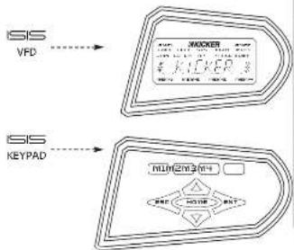
Meet the ISS Interface Indicate Status & Input Settings. The ISS is announced eye-sisi allows you to view the current conditions and settings of your amplifier as well as change the many user-adjustable settings. The ISS system consists of the VFD (Vacuum Fluorescent Display) and the nine soft touch buttons that make up the KEYPAID.
flowchart
graph TD
    A["SIS VFD"] --> B["MACKER"]
    C["KEYPAD"] --> D["KEYPAD"]
    B --> E["输入输出"]
    D --> F["输出输出"]
VFD DISPLAY
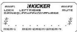
Here is a brief description of the indicators found on the VFD.
AMP1 - Indicates amplifier 1 is selected for adjustment. Only available in four channel amps.
AMPE indicates amplifier 2 is selected for adjustment. Only available in four channel amps.
LOCK - Indicates the amplifier controls are locked out and not usable.
LEFT - Indicates an action or adjustment of the left channel.
SYS - Indicates you are in the system menu
RIGHT - Indicates an action or adjustment of the right thanne.
MUTE - Indicates you are in the mute menu or the mute function is active.
VFD DISPLAY - cont
GAIN - indicates you are in the gain menu.
EQ - Indicates you are in the equalizer menu
LPF - Indicates vdu are in the lowcases filter menu.
HPF - Indicates you are in the high pass filter menu.
PHASE - Indicates you are in the phase menu.
KOMP - Indicates you are in the Kompressor menu.
MEM-1 - Memory preset 1 activated
MEM-2 - Memory preset 1 activated.
mem-3 Memory preset 1 activated
MEM-4 - Memory preset 1 activated.
KEYPAD
The keypad consists of nine buttons that allow you to adjust your amplifier.
m1 - Used to select memory preset 1 or to store current settings into preset 1.
me - Used to select memory preset 2 or to store current settings into preset 2.
ms - Used to select memory preset 3 or to store current settings into preset 5.
M4 - Used to select memory preset 4 or to store current settings into preset 4.
ESC - Used to exit the current menu.
ENT - Used to enter the selected menu.
HOME - Used to return to the Main menu and other functions explained later.
UP - Used to advance up through menu selections and/or adjust amplifier controls.
DOWN - Used to advance down through menu selections and/or adjust amplifier controls.
These controls and their usage will be explained later with more detail in each menu usage section.
End Panel Views
The ELAST Port is used to connect the Remote Bass Level Controller and for transferring control signals from one SX amplifier to another SX amplifier. An RJ45 cable is required to connect the ELAST Port (out) of one amp to the ELAST Port link of another. This is only required if you want to control more than one amplifier with the same Bass Level Controller. More details on this further in the manual.
The speaker terminals are custom-machined connectors with full protective shrouds and are designed to accept heavy gauge speaker wire assures maximum power transfer and damping with minimal power loss.
Cold-plated RCA Input connectors and PAST Jacks provide solid input and output connections for your pre-amp signal
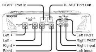
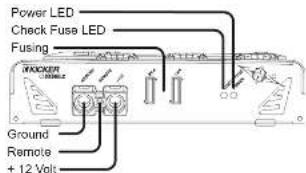
Custom-machined power block accepts up to a 2 Ga wire for both power and ground connections and up to an 8 Ga for remote turn-on assures maximum power transfer with minimal loss.
On board fusing in number of fuses vary by amp size to protect amplifier against over current conditions and reverse polarity.
Power LED indicates amplifier is powered up and operating.
Check Fuse LED indicates a fault with the end panel fuses. This could be fuses which are not seated properly, faulty fuses or blown fuses.
mounting
When selecting a location to mount your Kicker amplifier be sure it is structurally sound and that there are no items behind the area that could be damaged by the screws. Check for wiring, brake lines, fuel lines, gas tanks, etc.
All amplifiers generate heat under normal operation. Be sure to choose a location that allows adequate ventilation for the amplifier. Also consider that the air temperature inside an automobile's trunk can reach upwards of 140 degrees Fahrenheit. An amplifier mounted in the trunk may require additional cooling such as extra fans moving air around the amplifier's chassis or ventilating the trunk to exchange the hot air in the trunk for cooler air outside. If possible, mounting the amo in the passenger commute will allow cooler operation.
Remember that the controls on top of the amp will need to be accessible for adjustment later. Keep this in mind as you choose your amplifier's mounting location.
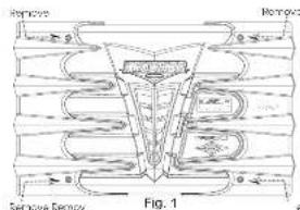
Now that you are ready to mount your amplifier, use the supplied 3mm alien wrench to remove the amplifier EndKaps. This will give you access to the mounting holes in the amplifier and all wiring connections.
See Fig. 1
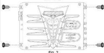
With the endcaps removed, you now have access to the four mounting holes in the mounting feet and all wiring connections. Drill 4 holes using a 7/64" drill bit and use the supplied #8 screws to mount the amplifier
WING
Signal is input into the amplifier using the low level RCA input connections. If your source unit does not have RCA output connectors you will need to use a Hi-Lo level signal adapter. See your Kicker dealer for more details on this.
The output IPAST: RCA jacks provide an unaltered signal output to feed another amplifier or component.
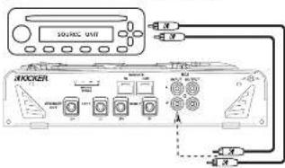
The use of twisted pair interconnects is recommended for all installations to minimize noise. When routing these cables through the automobile, try to keep them away from factory wiring harnesses and other power wiring. If you need to cross any of this wiring do so at a 30 degree angle to reduce the possibility for noise problems.
When working with power connections it is always recommended that you disconnect the battery to prevent accidents
The ground should be connected to the amplifier first before making any of the other connections. This wire should be as short as possible (24 inches or less) and connected to a paint/corrosion free solid metal area of the car's chassis. Use the same gauge wire as recommended for the amplifier's power connection to the battery. Adding an additional ground wire between the car battery's negative post and the car chassis of this same gauge for larger is also recommended.
If you ever need to remove the amp from the vehicle after it has been installed, the ground wire should be the last wire disconnected from the amplifier, just the opposite of when you installed it.
A fuse must be installed within 18 inches of the battery to protect the power wire feeding your amplifier. This fuse should be of at least the same value used in the amplifier but no higher than the capacity of the power wire. See the charts below for wire size and fusing recommendations.
| Model | Fuse Size | Wire Size |
| SX400.2 | 50A | 4 GA |
| SX500.2 | 60A | 4 GA |
| SX600.2 | 80A | 4 GA |
| SX900.2 | 120A | 2 GA |
| Wire Size | Length | Maximum Fuse |
| 8 Ga | Less than | 70 Amps |
| 4Ga | 10 feet In | 175 Amps |
| 2 Ga | length | 250 Amps |
| 0Ga | 400 Amps | |
| 8 Ga | 10 feet to | 40 Amps |
| 4 Ga | 20 feet In | 90 Amps |
| 2 Ga | length | 150 Amps |
| 0 Ga | 200 Amps |
System Diagrams
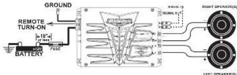
TWO CHANNEL OPERATION (STEREO)
SX.2 series amplifiers are capable of operating into a minimum impedance of 2 ohms per channel in stereo operation.
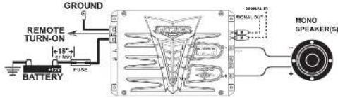
SX.2 series amplifiers are capable of operating into a minimum impedance of 4 ohms when in bridged operation.
GX B G### O###
STEREO AND MONO SIMULTANEOUSLY (SAMS)
SX 2 series amplifiers are capable of operating into a minimum impedance of 4 ohms mono and 2 ohms stereo simultaneously with the use of passive crossovers.
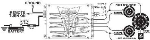
These are just a few of the many ways you can use your SX.2 series kicker amplifier. These system diagrams are designed to give you a basic understanding of the most common uses for this amplifier. For more complex systems please visit your local authorized Kicker dealer. You can also download the SX Technical Manual from our website at www.kicker.com for more detailed information and complex system diagrams.
USING THE SIGNAL OUTPUT JACKS (PAST)
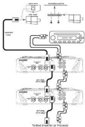
The Output (Pre Amp Signal Transfer) RCA jacks allow you to send the incoming signal from one Kicker SX series amplifier to another amplifier or processor without the need for Y-cables. The signal from the PAST jacks is identical to the signal led to the amplifier via its RCA input jacks and is not affected by any of the amplifier's built-in digital signal processing.
Most head units with high voltage outputs should be capable of driving up to ten amplifiers in a chain.
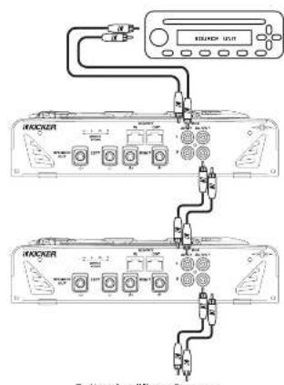
To Next Amplifier or Processor
USING THE REMOTE BASS LEVEL CONTROL & BLAST
You can use the Remote Bass Level Control to control the output of your amplifier from the front of the car.
Mount the controller by simply screwing the metal bracket to the chosen location and then slide the housing onto the bracket until it snaps into place.
Route the cable from the controller to the BLAST input jack on the amplifier chassis. That's it.
If you wish to control more than one amplifier with your remote, you will simply need to use a R-45 cable not supplied but available at any Radio Shack, computer store or electronics center to connect the BLAST output jack of the first amp to the BLAST input jack of the next amplifier.
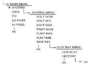
Your KICKER SX series amplifier uses the latest in Digital DSP control and provides you with valuable operational information about your amplifier, real-time diagnostics and a full multi-level menu-driven operating system to access and adjust your amplifier.
The menu system is designed in layers. There is a starting point and you keep drilling down until you get to the menu item you want to view or change. This menu tree is an example of how the SX menu structure is set up.
NOTE: Not all the menus and menu items are shown below. DEFAULT SCREEN
flowchart
graph TD
    A["MAIN MENU"] --> B["SYSTEM"]
    B --> C["GAIN"]
    C --> D["EO"]
    D --> E["LO-PASS"]
    E --> F["HI-PASS"]
    F --> G["..."]
    G --> H["..."]
    H --> I["SICK RAY"]
    I --> J["CURRENT"]
    J --> K["HISTORY"]
    K --> L["..."]
    L --> M["SICK RAY MENU"]
    style A fill:#f9f,stroke:#333
    style B fill:#ccf,stroke:#333
    style C fill:#cfc,stroke:#333
    style D fill:#fcc,stroke:#333
    style E fill:#cff,stroke:#333
    style F fill:#ffc,stroke:#333
    style G fill:#cfc,stroke:#333
    style H fill:#fcc,stroke:#333
    style I fill:#cfc,stroke:#333
    style J fill:#fcc,stroke:#333
    style K fill:#cfc,stroke:#333
    style L fill:#fcc,stroke:#333
As you can see there can be an infinite number of menu levels and each one of these menu levels can have an infinite number of its own items.
Navigating this simple menu structure is very easy using the 5-way keypad.
You use the UP and DOWN keys to scroll through the available menu items, and the ENT key is used to select that menu item. The ESC key backs you up one menu level from where you are, and the HOME key can returns you all the way to MAIN MENU by pressing and holding it for 1.5 seconds.
For example let's begin at the DEFAULT SCREEN; our goal is to get to the HISTORY menu. Pressing the ENT key would get us to MAIN MENU. Now use the UP and DOWN keys to scroll to SYSTEM, and then press the ENT key. Now you are in the SYSTEM MENU. Using the UP and DOWN keys again you scroll to SICK BAY and press the ENT key. You are

Continuing our example, we are now in the HISTORY item in the SICK BAY MENU. If we press the ESC key we would go back up to the SICK BAY MENU if we
press the ESC key again we would go to the SYSTEM MENU. One more press of the ESC key and we are in the MAIN MENU.
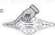
Let's start at the HISTORY item in the SICK BAY MENU again but instead press and hold the HOME key for 1.5 seconds. Doing this will take us all the way back to the MAIN

holding the HOME key will return you all the way back to the MENU ITEM you started with in the MAIN MENU, no matter how deep in the menu level structure you are. Pretty cool!
This is a very quick way to return to the MAIN MENU after drilling down several menu layers to view or change an item.
When adjusting any amplifier control the UP and DOWN arrow keys have 2 speeds, normal and accelerated.
Pressing and releasing the key repeatedly will scroll through the menu items at normal speed.

Pressing the key and holding it in for longer than 1.5 seconds will activate the accelerated scrolling mode and scroll through the menu items at a much faster rate. Releasing the key will return it to normal speed mode.

Don't try to scroll through every 1/12 octave step without it!
menu System
The menu system layout is as follows:
DEFAULT - This menu is displayed when your amp is operating and no adjustments are being made to your amplifier. This information scrolls through the display one after the other and then repeats.
1J 2:106P - Hey, we needed a brand plug for us since this amp is sooooo could!
2.1 ·s 0.5 · Displays the current voltage at the amplifier's + 12 volt battery input terminal.
3.1 - NFS F or 4.2 - NFS F - Displays the current temperature of the amplifier in celsius orahrenheit.
4.1 RSC /RSC - Model name of the amplifier or the name you have changed it to.
5.1 (SOPP-MAF) - Current memory preset in use of any or the name you have changed it to.

If you want to freeze the scrolling display simply press the HOME key and the scrolling will stop.
Now you can manually select the item you wish to have displayed by using the UP or DOWN keys.
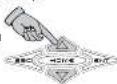
If you want the display to continue scrolling simply press the HOME key again.
MAIN - This menu is the first menu accessed from the DEFAULT menu and is the gateway to all the settings and information on your SX series amplifier.
To enter the MAIN menu simply press the ENT key while in the DEFAULT menu.

The available selections in the MAIN menu are:
SYSTEM GRIN BD LD 170 RD 985 HALL NOTE B32997 SECUR
Use the UP and DOWN arrow keys to scroll through the available selections in the MAN menu.
When you have the menu item selected that you want to view or adjust simply press the ENT key to select it.


SYSTEM MENU - This menu item contains many diagnostic tools and first time setup options. Use the UP and DOWN arrow keys to scroll through the options and press ENT to select. Press the ESC key to return to the SYSTEM menu.
1.1 VOLT/ON - Displays the current voltage at the amplifiers +12 volt terminal
2.1 Q T 2007 - Displays the lowest voltage seen at the amplifiers +12 volt terminal since being installed.
3.1 _L - Displays the highest voltage at the amplifiers +12 volt terminal since being installed,
4.1 TEM FLOW - Displays the current temperature of the amplifier
5.1 TGNP M2 - Displays the highest temperature the amplifier has reached since being installed.
6.1 PSFT Time - Displays the total time the amplifier has been powered up since installation in 1/10th of an hour increments
7.1 S/IFM - Contains several diagnostic tools. Once in this menu you use the UP and DOWN keys scroll through LUTORY, HISTORY and KEY, TOUSE options. Press the ENT key to select.
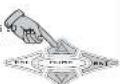
7a.1 (2023) shows amplifiers current status or fault code. The 6 possible codes are:
- No problem, normal operation. - Thermal cutoff protection engaged. - short circuit protection engaged. - High voltage protection engaged. - Faulty or blown power fuse.
When you are done viewing the current status press the ESC key to return to the S BAY menu.

7b. JH'S T02Y logs the last 5 far long ago they happened when compared to the RUN TIME log.

Use the UP and DOWN keys to select the KISUHY log entry you want to view

Press and hold the ENT key to view the time it happened.
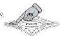
When you are done viewing the history press the ESC key
SICK BAY - cont
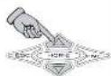
7cJ PIR, 4015C is a built-in pink noise generator to test operation of the amplifier
Use the UP and DOWN keys to select DIVE 10 or DIVE 20
When the PINK NOISE is ON the LEFT and RIGHT indicators in the VTD will blink on and off.
When you are done using the PINK NOISE generator press the ESC key to return to the SICK BAY menu.
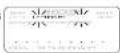

NOTE...
If you exit the SICK BAY menu with the PINK NOISE generator still on, the LCK and PINK VFD Indicators will remain blinking as a reminder.
8.1 ROP (M) - Here you can assign a unique name to your KCKER SX amplifier. This name will replace the model name in the DEFAULT screen, if you change your mind and do not want to change the name, press and hold the HOME key for 1.5 seconds BEFORE making any changes
The ESC and ENT keys move the cursor left or right to select which character to change.

When you are finished press and hold the Home key for 1.5 seconds to save your new amplifier name
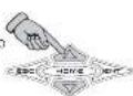

9.1 (54) (24) - Here you can change the names of the memory locations. The factory defaults are
[Unreadable]
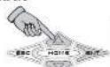
Use the UP and DOWN keys to select the memory location name you want to change and then press the ENT key to select it. If you change your mind and do not want to change the name, press and hold the HOME key for 1.5 seconds BEFORE making any changes

The ESC and ENT keys move the cursor left or right to select which character to change.

Use the UP and DOWN keys to change the character displayed

When you are finished press and hold the HOME key for 1.5 seconds to save your new memory name.
Repeat the above steps to rename the other presets.
10.1 250-6 257 This feature is currently not used but is reserved for future expansion.
11J 500 PNTF - sets the input voltage window of the UltraMatch gan control. Possible choices are:
Select the one closest to the maximum RCA input voltage you expect to send to the amplifier.
Use the UP and DOWN keys to select your voltage. Press the ESC return to the MAIN menu.
12.1 Bypass Bypass - Bypasses all DSP processing and sends the input signal directly to the amplifier.
Use the UP and DOWN keys to select IMPRSS (OR IMANS OFF). Press the ESC key to return to the MAIN menu.
13.1 COMPRESSION This adjusts the KOMPRESSOR activation threshold. Range is +24 dB to -24 dB to allow for different sized speakers or listener tastes. C is the default factory setting.
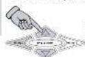
Use the UP and DOWN keys to select your setting and then press the ESC to return to the MAIN menu.
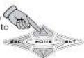
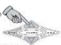
14.1 SFP BY - Several options to allow customizing the amplifier's VFD display.
14a.) VFD display. Five selectable levels. (0/0/0/0) - dimmest setting.
LUN (2) STEN HON
(8) 100 - brightest setting
14b.) (Lan) L. T. Selects between Celsius (LLLUS) or Fahrenheit (AFR2019457) for temperature readouts.
14CJ 197 T 108F - Adjusts the speed of the scroll in the Default Screen display. Determines now long each menu item stays in the display before scrolling to the next item. Adjustable from 1 - 11 seconds.
14d.) SENS/HEP - Option to turn on or off the screensaver. When an I/O/O the display will go to sleep when there is no button activity for 60 seconds. Pressing any button once will wake up the display. The O/P selection turns off the screensaver and the display is always on.
15.1.00 - 00F - Set your own lock code! The factory default is 00 but you can change it and create your own code with up to 10 characters.
The ESC and ENT keys move the cursor left or right to select which character to change

Use the UP and DOWN keys to change the character displayed

When you are finished press and hold the home key for 1.5 second to save your new amplifier lock code. IMPORTANT! Be sure to write this code down for future reference.

16.1 PNET RSP - this option resets all adjustable settings back to their original factory defaults.
Use the UP and DOWN keys to select UP Post for UP Post and then press the ENT key to perform the selected action.
17.1 B204 - This menu item will display information about the DAP (Digital Audio Processor) hardware, software and build date.
Use the UP and DOWN keys to view the DSP Version, Software Version, Hardware Version and Build Date. Press the ESC key to return to the MAIN menu.
S2017 MENU - Here is where you adjust your amplifier's gain control settings.
Press the ENT key to enter the CAIN menu
Use the UP and DOWN keys to scroll through Left channel Right channel or DOWN options and then press the ENT key to select
Now use the UP and DOWN keys
to increase of decrease the gain of the selected channels in .5 dB increments from 0 dB to +12 dB.
Press the ESC key to return to the LCP, FROM, JOIN options menu. You can now adjust another channel on this amplifier.
When you are done adjusting the gain press the esc key while in the GAIN menu to return to the MAIN menu.
NOTE...
While adjusting the GAIN you will notice the GAIN indicator on the ISS VFD display is it. This indicates you are in the GAIN menu.
The LCCF and/or RISVIF indicator will light up to indicate which amplifier channels: you are currently adjusting
50 MENU - Here you can adjust the single band parametric equalizer. Your options are FEDUCY, INTU, M1 and RUS-10.
Press the ENT key to enter the 50 menu.
Use the UP and DOWN keys to choose one and press the ENT key to select it.
FORDENY selects the center frequency of the EQ and can be set at any 1/12th octave frequency from 30 Hz - 20 kHz. (c) Hz to dux5 Hz
Use the UP and DOWN keys to select your frequency. Press the ESC to return to the EQ menu.
20.000 20.000 better known as Q: can be set from -5 to -1 in .5 increments. In simple terms, lower Q effects more frequencies around the center frequency while higher Q effects fewer frequencies around the center frequency.
Use the UP and DOWN keys to select your Q value. Press the ESC to return to the EQ menu.
RMS1/7W is how much you want to boost or cut the equalizer and has a range of 0.32 to 0.33 in 5 dB steps Use the UP and DOWN keys to adjust each setting and the ESC
key to return to the EQ menu
When you are done adjusting the EQ press the esc key while in the EQ menu to return to the MAIN menu.
NOTE... While adjusting the EQ you will notice the EQ indicator on the VFD display is it. This indicates you are in the EQ menu.
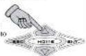
1.0-9995 MENU - Here is where you adjust the low pass crossover.
Press the ENT key to enter the LO PASS menu.
Use the UP and DOWN keys to scroll through ENERGY and OCEC. From the TNT order,
one you want to adjust.
HEDUCKY selects the crossover point and can be set at any 1/12th octave frequency from 30 Hz to 20 kHz.
(2) 10
Use the UP and DOWN keys to
select your frequency. Press the
ESC 100% to be TO-FASS
mpm.
SLC selects the rolloff of the crossover and can be set
from 10 to 5 in 6 dB steps
Use the UP and DOWN keys to
select your slope. Press the ESC return to the LO-PASS mem.

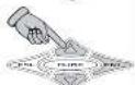
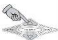
When you are done adjusting the EQ press the ESC key while in the EQ menu to return to the MAIN
NOTE...
While adjusting the LO-PASS crossover you will notice the indicator on the VFD display is lit. This indicates you are in the LO-PASS crossover menu.
The KICKER SX amplifier monitors and prevents any low pass crossover point from being any closer than 1/3 octave from the high pass crossover point. If you cannot set the low pass crossover where you want then check the 15^TM indicator and see if it is flashing, if it is then you need to go to the HI-PASS menu and raise the high pass crossover point.
This is done as a safety precaution to prevent a notch filter condition.

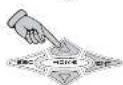
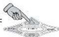
MENU - Here is where you adjust the high pass crosses.
Press the ENT key to enter the III-PASS menu.
Use the UP and DOWN keys to scroll through APP/PPY and Q/Q and press the ENT to select the one you want to adjust.
^1 COLDY selects the crossover point and can be set at any 1/12th octave frequency from 10 Hz to 16 kHz. ( 3 ) m, 3 ( 3 )
Use the UP and DOWN keys to select your frequency. Press the key to return to the HI-PASS menu.
S_1 ^32 selects the rolloff of the crossover and can be set from U^+ to S in 5 dB steps.
Use the UP and DOWN keys to select your slope. Press the ESC to return to the HI-PASS menu.


When you are done adjusting the EQ press the ESC key while in the EQ menu to return to the MAIN menu.
NOTE...
While adjusting the HI-PASS crossover you will notice the √√ indicator on the √≡ VFD display is lit. This indicates you are in the HI-PASS crossover menu.
The KICKER 5X amplifier monitors and prevents any high pass crossover point from being any closer than 1/3 octave from the low pass crossover point. If you cannot set the high pass crossover where you want then check the L+ indicator and see if it is flashing. If it is then you need to go to the LG-PASS menu and lower the low pass crossover point.
This is done as a safety precaution to prevent a notch filter condition.
MENU - Here you can switch the polarity of each
channel(s) output between 0 or 100
Press the ENT key to enter the
PHASE menu.
Use the UP and DOWN keys to
scroll through ^2 , ^2 , and ^2
Press the ENT to select the cue you
want to adjust.
Use the UP and DOWN k
to select from 0.25% or 0.3
ESE. Press the ESC key to
make your selection and return to
the PHASE menu.
You can now select another channel
to adjust or press the ESC key to
return to the MAIN menu.




NOTE...
While adjusting the PHASE you will notice the
indicator on the ISS VFD display is lit. This indicates you
are in the PHASE mean
There is also a LUT and a MUS indicator that will light up to let you know which channel (Left and/or Right) that you are
currently adjusting.
MENU - Here you can route each channel(s) output for
setup or testing purposes.
Press the ENT key to enter the
MUTE menu.
Use the UP and DOWN keys to
scroll through 1574, LEE and
PINS Press the ENT to select
the use you want to adjust
Use the UP and DOWN keys
to select from 0.01 or 0.02
Press the ESC key to make your
selectran and return to the MUTF
nemu,
You can now select another channel
to adjust or press the ESC key to
return to the MAIN menu.





MENU - cont.
NOTE.
While adjusting the MUTE you will notice the GUTE indica-
for an the ⑨⑤ VFD display is bit. This indicates you are in
the MITE mena
There is also a LEFT and a RIGHT indicator that will light up
to let you know which channel (Left and/or Right) that you are
currently mating
If you cost the MUTF menu with any channel(s) rated, the
LEC^T and/or P(158) ^T indicators will flash to indicate this.
MENU - Here you can select which Kompressor
setting you wish to use. The SX amplifier utilizes a full digital
compressor circuit to break the amplifier and the sound to
your unique needs.
Press the ENT key to enter the
KOMPRESSOR MEM.
Use the UP and DOWN keys on
scroll through 1756, LONION
[Unreadable]

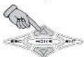
Press the ESC key to accept your
selection and return to the MAIN
menti

NOTE...
While adjusting the Kompressor you will notice the
indicate on the ISS VFD display is lt. This indicates yes
are in the KOMPRESSOR menu.
See the specifications pages for a brief description of each
Kompressor setting and some general guidelines for their use.
SFF/INTY MENU - Here you can lock down your amplifier to prevent any access to the settings. The DEFAULT screen is still active and you can select any of the four presets... but that is in
Press the ENT key to enter the KOMPRESSOR menu.
Use the UP and DOWN key select LOCK UP or ADD LET and then press the ENT key to accept your setting
If you selected 105×17.42 the display will now show 105× and the lock indicator will be on. The menus are now locked. Press the esc key to return to the DEFAULT scrolling screen.
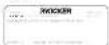
If you selected XMT LOC then you will return to the MAIN menu and the amplifier will remain unlocked.
NOTE..
While your amplifier is in lock down you will notice the LCD indicator on the VFD display is lit. This indicates your amplifier is locked down and will require a code to unlock it before any adjustments can be made.
UNLOCK AMPLIFIER
You do remember your lock code right? You better because that is now the only way in! If you have not changed it then it is still at the factory default of .22.

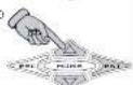
To unlock your amplifier press the
ENT key. The display will show
N.0X Press the ENT key again
You will now enter your code to
unlock the amplifier.
The ESC and ENT keys move the
binking cursor left or right to select
which character to enter
Use the UP and DOWN keys to
enter the character.
etcl
When you are finished press and hold
the HOME key for 1.5 seconds to
enter your unlock code




If the code is correct the amp will unlock and drop you back into the security menu, if not, then read on...
UNLOCK AMPLIFIER - cont.
if you enter the wrong code the display will flash the message. My UI is and then return you to ALL screen.
Press the ENT key to enter your lock your code again.

You will need to call KICKER directly at 6051 624-8383 to handle this situation. You will need your amplifier's serial number AND your receipt as the guys and gals answering the phone will need this information from you to help you out
So...before you call, gather this information up and have it. "Ready to save us some time on the phone. Cool? Cool!"
Better yet, take the time RIGHT NOW to fill out the first page in this manual and STAPLE your receipt to it. That way if or when you need service like forgetting your lock code? you will have all the information you need right there in front of you.
Memory Presets
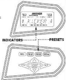
There are four memory preset keys each with an indicator above it in the VFD display. The indicator will illuminate if that
immediate if that memory preset is currently in use,
Each preset stores all the values for each of the following amplifier controls:
• ) N##l • ) #S • ) LD-#SS • ) #L-#SS • ) P#SE • ) #TC • ) #C#P#S###
flowchart
graph TD
    A["INDICOR"] --> B["INDICORS"]
    B --> C["PRESETS"]
    C --> D["AND"]
    C --> E["NOT"]
    D --> F["101"]
    E --> G["102"]
    E --> H["103"]
    E --> I["104"]
    F --> J["AND"]
    G --> K["NOT"]
    H --> L["NOT"]
    I --> M["NOT"]
This gives you the ability to dial in four completely different amplifier settings and store them in presets for instant recall later.
It's like a preset for your favorite radio stations...only better
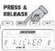
STORING A PRESET
Make all the adjustments you want to have stored in the preset and return to the DEFAULT screen.
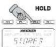
To store your settings into a preset simply press and hold the desired memory key until the VFD display flashes 500MHz. Then release the memory key. The indicator which matches the preset you used will illuminate.
RECALLING A PRESET
To recall a memory preset simply press and release the key. The matching indicator will light up and the amplifier change all the corresponding controls to the values assigned to the memory preset.
PRESET PRESETS
Ok, we know that sounds like a certain pizza commercial, but seriously the four memory presets come with settings already in them.
You can use these as a starting point to do your own tweak ing or for quick push-a-button-and-be-done setup.
Any preset you store will replace the ones that come from the factory. You can reset all four preset back to factory defaults anytime simply by doing a reset in the RESET AMP menu.
Here are the settings in each preset from the factory
| MEMORY-1 | MEMORY-2 | MEMORY-3 | MEMORY-4 | |
| GAIN LEVEL 5 DB | DB 6 DB | DB | ||
| FG FREQUENCY 7 | H 20 H 7 | H 7 40 H 7 | ||
| FG BOOST CUT FL | FLAT FLAT FL | FLAT FLAT FL | ||
| CG BADNDINT13 | F 3 F | |||
| LO PASS SLOPE | OFF | OFF | 24 DB | 24 DB |
| LG PASS RFG | 2005 H 7 | 2005 H 7 | 8 H 7 172 H 7 | |
| HADS SLOPE | 12 DB | 24 DB | 24 DB | 24 DB |
| LFP PASS FLG | 2512 H 14 | 2512 H 14 | ||
| PHASE CAR CH | O DUGHELL | O DUGHELL | O DUGHELL | O DUGHELL |
| MUTE LAN DR | OFF | OFF | OFF | OFF |
| KOMPRESSOR | OFF | OFF | OFF | OFF |
| ROXP RADJ | D 02 9 201 | D 02 9 201 |
In more general terms, each preset offers you these options.
Memory-1 sets the amplifier into full-range mode with a infrasonic filter (often called subsonic filter) to protect the speakers from harmful ultra-low frequencies.
Memory-2 sets the amplifier into low-pass operation with a infrasonic filter. For use when the amplifier is driving a subwoofer
Memory-3 sets the amplifier into high-pass operation. Used for powering up a set of coaxial or component speakers when another amp is driving a subwoofer.
Memory-4 sets the amplifier up for mid-bass duty. Perfect for a set of KICKER mid-bass drivers
As stated before you can always start with one of these pre-set, tweak it to fit your installation and then save your settings into a new preset.
TROUBLESHOOTING
If your amplifier does not appear to be working, check obvious things first such as blown fuses, poor or incorrect wiring connections, crossovers set improperly, gain controls Impropery set, etc.
There are two LEDs on the end panel of your KICKER SX series amplifier, one green and one red. The green LED indicates the amplifier is turned on. The red LED indicates that there is a fault condition with the end panel fuses and they need checked.
The power indicator on top of the amplifier which illuminates the model badge follows the same function as the green LED.
OGreen LED off, no output
P with a volt ohm meter (VOM) check
+ 12 volt power terminal should read +12V to +16V .
^a Remote turn-on terminal (should read +12V to +16V).
Ground terminal to chassis ground (should read 0)
OGreen LED on, no output
Check amp status in SCK DAY
Check GAIN RANGE in SYSTEM menu.
Check GAIN LEVEL in GAIN menu.
Check if MUTE is activated
Test amp using PINK NOISE in SICK BAY menu.
☑amp makes noise using PINK NOISE then:
Check RCA cable and connections.
Check for signal on RCA cable with VOM in AC
position
Substitute known good source unit
If amp does not make noise using PINK NOSE then
Check speaker connections
a) Test speaker outputs with known good speaker
Other Symptoms
☑Amo is very hot, no output.
a)Thermal protection is engaged. Check SICK BAY to
verify. Check for proper impedance at speaker
terminals. Also check for adequate airflow around
amplifier
☑Amo shuts down while vehicle is running.
Over Voltage protection engaged. Check SICK BAY
to verify. Voltage to the amplifier is not within the
3-16 volt operating range. Have automobile
charging/electrical system inspected.
☑ Amp only plays at low volume levels
Short circuit protection engaged. Check SCK BAY
to verify. Check for speaker wires shorted to each
other or the vehicle chassis. Damaged speakers or
operating amplifier below minimum recommended
impedance will also cause this.
√Weak bass output
Change the phase of the LEFT channel in the PHASE
menu, if bass improves then one speaker channel is
out of phase (polarity). You can leave PHASE changed
for this channel to fix the problem or better yet:
Check speaker connections to amp and speakers to
determine which one is wrong and correct. Be sure
to set the PHASE of the LEFT channel back to original
setting after correcting wiring connections
○Alternator nholsemining sound that varies with engine RFMs
Check for damaged RCA cables
Check routing of RCA cable.
Check source unit for good ground
Check GAIN RANCE in SYSTEM menu, turn down if set too
nign.
Check GAIN in MAIN MENU, turn down if set too high
CAUTION: When jump-starting the vehicle, be sure that connections made with jumper cables are correct. Improper connections (+ to - & - to +) will result in blown amplifier fuses as well as failure to other systems in the vehicle.
If you have more questions about the installation and operation of your new KICKER amplifier, see the Authorized KICKER Dealer in your area. You may also call our Technical Services Line at 4051624-8583 for assistance or visit our website at www.KICKER.com
Kompressor
Here is a brief explanation of each KOMPRESSOR setting.
10.1.29 - This preset applies expansion below the threshold point to provide a fuller sound at lower volume levels. Effect decreases at higher volume levels. Nice effect for someone wanting a fuller sound at low to moderate listening levels.
- This preset applies expansion above the threshold point to provide a nice quick punch or attack to the music. Effect increase with higher volume levels. Like music with a quick and punchy sound? Give this one a try.
- Provides a quick clamp to dynamic peaks while still allowing a full sound to come through. Effect increases at higher volume levels. Like to play it loud but want to protect your speakers? Want low level details to come through over road noise? Want a more even volume level to your music? All can be achieved with this preset.
U+ - Pretty much says it all. This turns the KOMPRESSOR off. This is the factory default setting.
After selecting your KOMPRESSOR setting you can adjust its effect using the KOMPRESSOR ADJUSTMENT (LIGHT/TAU) setting located in the SYSTEM menu. There you can change the threshold point for each of these settings to customize the KOMPRESSOR effect to fit your speakers, car or personal tastes.
A few words on the Kompressor. The effect is most noticeable in the bass area of your music and the descriptions above apply to that area of your music (Bass/Midbass). You can use the Kompressor in any amplifier configuration (Low Pass, High Pass, Band Pass or Full Range) but we feel the best results are obtained when with the amp is in a Low Pass (subwoofer) or Band Pass (midbass) situation.
A few exceptions to this rule are:
The HEPLW2 setting is good for use in any configuration as it helps control dynamic peaks and limit distortion at higher output levels.
The CONTOUT setting is also another good all around use setting and when used in Full Range or High Fass configurations tends to enhance the vocal and top end of the music. Great for helping to cover up interior noise.
The KU-AL setting is really geared for bass and midbass duty.
The possibilities are almost endless! Tweak away!
Performance
Model SX400.2 SX500.2 SX600.2 SX900.2
RMS Power
In Watts, All Channels Driven
@ 13.8V, 492 Stereo, 0.02% THD 88 x 2 113 x 2 138 x 2 213 x 2
@ 13.8V, 29 Stereo, 0.2% THD 175 x 2 225 x 2 275 x 2 425 x 2
@ 13.8V, 4Ω Mono, 0.4% THD 350 x 1 450 x 1 550 x 1 850 x 1
Dynamic Power
In Watts, All Channels Driven
@ 14.4V, 40 Stereo, 1% THD 100 x 2 125 x 2 150 x 2 225 x 2
@ 14.4V, 2Ω Stereo, 1% THD 200 x 2 250 x 2 300 x 2 450 x 2
@ 14.4V, 40 Mono, 1% THD 400 x 1 500 x 1 600 x 1 900 x 1
Length With EndKaps 16" 19.25" 22.5" 25.75"
140.64cm (48.90cm) (57.15cm) 165.41cm
| Fusing | 25A x 2 | 30A x 2 | 40A x 2 | 40A x 3 |
| Recommended Power & Ground Wire | 4 GA | 4 GA | 4 GA | 2 GA |

Height:
width:
Length Without EndKaps:
Frequency Response:
Input Sensitivity:
Signal-to-Noise Ratio:
High Pass Crossover Freq.:
High Pass Crossover Slope:
Low Pass crossover Freq.:
Low Pass crossover
Kicking Frequency: Kick20 Bandwidth
Kicking Bandwidth (Q): KickEQ Report/Cut:
Kicking Boost/Cut: Remote Bass Love
Remote Bass Level Control. Power & Ground Terminals
Power & Ground Terminals.
DSP Reaction Time / Delay:
DSP Reaction Time) Friend's Reaction:
Stranger's Reaction:
2.5 Inches / 6.35 centimeters
10 inches / 25.4 centimeters
Subtract 5 inches (12.7 cm) from chart above
20 Hz - 20 kHz, +0 / -1 dB
62.5 mV - 16 V
100 dB
10 Hz - 16 kHz In 1/12 Octave steps
0 (off) - 36 dB in 6 dB steps
30 Hz - 20 kHz In 1/12 Octave steps
0 (off) - 36 dB in 6 dB steps
20 Hz - 20 kHz in 1/12 Octave steps
.5 to 10 in .5 steps
+7-18 dB per octave included with each a
INCLUDED WITH EACH AMPFITER WILL accent up to 2 Gauge w/
will accept up to 2 Gauge wire 7 milliseconds in submitudes. For
.7 Minisecorius in other words: Kest Hall That chirrles off The vittle
That Shizzle's Off The Hizzle Rude, Sweet
Dude...sweet...
ELECTRONICS LIMITED WARRANTY
Kicker warrants this product is a free front packet in material and workership under normal use for a period of 90 DAYS from date of original purchase with receipt. When purchased from an automobile truck, Kicker is warranted to be sold at the same price. For example, it is also a \$100.00 per unit (including the other vehicle). Kicker is labeled "S Stock" is warranted for 90 DAYS from date of original purchase with receipt. If listed "B Stock" and purchased from an automobile truck, Kicker is warranted for ONE Oil (NAV) from date of purchase with receipt. In all cases you have the original document should provide to be necessary under this product or sale. The company's sales will not be satisfied with the warranty granted. Kicker will replace or repair at the discretion on the defective merchant and will equal its merchandise, as no change. Warranty replacements on "S Stock" merchandise may have cosmetic scrapies and blomishes. This product is also a product that is available to the other products.
This warranty is valid only for the original purchaser and is not extended to payee of the product subsequent to the original purchaser. Any application is implied warranties are limited in duration to a period of the express warranty as probable herein beginning with the date of the original purchase at retail, and no warranties, whether express or implied, shall apply to the product, thereafter. Some states do not allow for liabilities on implied warranties, therefore these
This warranty gives you specific legal rights; however you may have other
rights that vary from state to state.
WHAT TO DO IF YOU NEED WARRANTY OR SERVICE
Selective interrhage must be returned to your local authority sea water. Designs dricket: Dealer for warranty. Assistance in locating an Authorized Dealer can be obtained by writing or calling Stillwater Designs direct. You can confirm that a dealer is authorized by asking to see a current authorized dealer window postal.
If it becomes necessary for you to return defective merchandise, call the Kicker Customer Service Department at 10/51/24-39/10 for a Return Authorization IRMS number. Package all defective items in the original container or in a package that will prevent shipping damage, and return to
Stillwater Designs, 5021 North Perkins Road, Stillwater, OK 74075
The RWA number must be clearly marked on the outside of the package. Return only defective components. Return of entire cabinets, system packs, pairs, etc. increases your return freight charges. Non-defective items received will be returned freight policy.
Include a dated proof-of-purchase stating the Customer name, Dealer name, product purchase and date of purchase. Warranty expiration an item without proof-of-purchase will be determined from type of sale and the manufacturing date code. Freight must be prepaid; items received freight collect will be refused.
Failure to follow these steps may void your warranty. Any questions directed to the Kicker Customer Service Department at 0405624-9510
WHAT IS NOT COVERED?
This warranty is valid only if the product is used for the purpose for which it
was designed.
It does not cover:
• Damage due to improper installation
- Subsequent damage to other companies - Europe caused by pressure to move it up
- Damage caused by exposure to this scale, excessive heat, chemical cleaners, and/or UV radiation.
• Damage through neuvence, misuse, accidents, or abuse. Repeated returns for
the same damage may be considered abuse.
• Any cost or expense related to the removal or installation of a procedure.
- Speakers damaged due to amplifier closing or distortion.
• Items previously repaired or missed by any unauthorized repair facility.
- Recruit shipments of non-specific items. - Products with increased or missing bps
- Products returned without a Return Authorization RNA number
• Freight Damage.
- The cost of shipping product to ticker.
• Service performed by anyone other than Kicker
- Speaker with any foreign menu use for games, material
HOW LONG WILL IT TAKE?
Kicker strives to maintain a goal of 24-hour service for all returns.
Delays may be Incurred. If lack of replacement inventory or parts is
encourtered
INTERDETICDEL WEBBENTY
Contact your international Officer deals or distal the core course, specifically
FOR THE YEAR OF THE COUNCING
pruchta at 24 years, 25 and 30, published

F.D. Box 439 • Stillwater, Oklahoma 74376 • U.S.A. • 405 624-8310
ICFPR drivers are capable of producing sound levels.
that can permanently damage your hearing! Turning
UP a system to a level that has audible distortion is more refracting (in use was ultraterior to an
WARNING: made carrying as your hands chair matching to an undistorted system at the same volume level. The
WARNING. threshold of pain is always an indicator that the sound
LEVEL is too loud and may permanently damage your
Please use common sense when controlling volume
Please see the following details: You can
notes
Pizza Delivery
56.2 3000000000
- 2017年1月1日
Chic's Numbers
HOOK UPS
38
5X P 2000000000000
GX P. G### OTE F###
39
- KICKER®
- Attention:
- Congratulations!
- SIS
- VFD DISPLAY
- VFD DISPLAY - cont
- KEYPAD
- End Panel Views
- mounting
- WING
- System Diagrams
- TWO CHANNEL OPERATION (STEREO)
- STEREO AND MONO SIMULTANEOUSLY (SAMS)
- USING THE SIGNAL OUTPUT JACKS (PAST)
- USING THE REMOTE BASS LEVEL CONTROL & BLAST
- menu System
- SICK BAY - cont
- NOTE...
- NOTE.
- NOTE..
- UNLOCK AMPLIFIER
- UNLOCK AMPLIFIER - cont.
- Memory Presets
- STORING A PRESET
- RECALLING A PRESET
- PRESET PRESETS
- TROUBLESHOOTING
- Kompressor
- Performance
- Model SX400.2 SX500.2 SX600.2 SX900.2
- RMS Power
- Dynamic Power
- ELECTRONICS LIMITED WARRANTY
- WHAT IS NOT COVERED?
Brand : KICKER
Model : SX500.2
Category : Car radio