MBC70 - Microwave Creda - Free user manual and instructions
Find the device manual for free MBC70 Creda in PDF.


| Product Type | Built-in Microwave Oven |
| Brand | Creda |
| Model | MBC70 |
| Installation Cavity Height | 450 mm (±2 mm) |
| Installation Cavity Width | 560 mm (±5 mm) |
| Installation Cavity Depth | 560 mm (minimum) |
| Cabinet Width Requirement | 600 mm |
| Maximum Supported Weight on Shelf | 25 kg |
| Power Supply | 230 V, 50 Hz (earthed socket) |
| Power Cord | Pre-fitted with plug |
| Electrical Connection | Earthed socket, accessible after installation or via isolator switch with 3mm contact gap |
| Installation Accessories Included | Foam air guide set, carrier rails, adhesive cushion, metal air guide, rear air guide, upper exhaust guide, black tape strips, bottom grille, top grille, side trims, screws, paper template |
| Ventilation Requirement | Minimum 45 mm x 560 mm vent, must not be obstructed |
| User Manual Language | English (available in other languages upon request) |
| Disposal | Refer to local regulations; do not dispose with household waste |
Frequently Asked Questions - MBC70 Creda
User questions about MBC70 Creda
0 question about this device. Answer the ones you know or ask your own.
Ask a new question about this device
Download the instructions for your Microwave in PDF format for free! Find your manual MBC70 - Creda and take your electronic device back in hand. On this page are published all the documents necessary for the use of your device. MBC70 by Creda.
USER MANUAL MBC70 Creda
Installation Instructions
Fig. 1
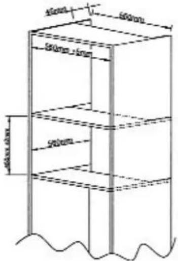
Fig. 2
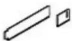
(A)
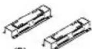
(B)
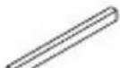
(C)
(D)
(F)
(G)


(M)

(N)
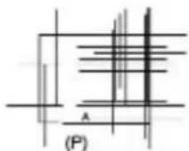
Fig. 3 Fig. 4
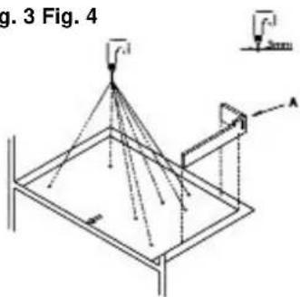
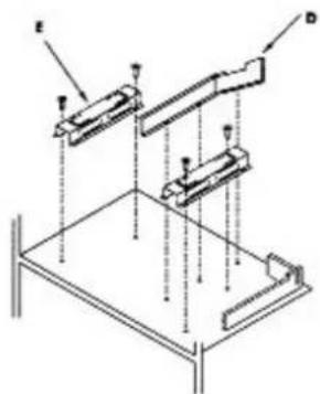
Fig. 5
natural_image
Diagram of a device interior showing internal components and external wiring (no text or symbols)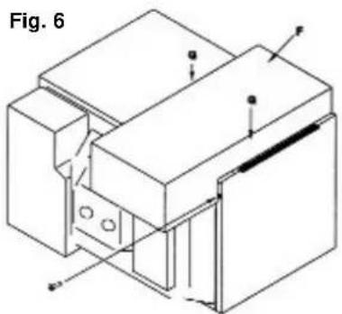
natural_image
Technical line drawing of a mechanical assembly with labeled components (no text or symbols)Fig. 7
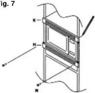
Fig. 8
natural_image
Technical line drawing of a mechanical assembly with a tool inserted into a component (no text or symbols)A. Please read these instructions carefully before you begin
-
The microwave oven can be installed into a 600mm wide Cabinet. The installation cavity must have the following internal dimensions:
Height: 450mm (± 2mm)
Width: 560mm to (± 5mm)
Depth: At least 560mm
Vent: Min 45mm x 560mm applicable to all panels.
(Ensure the vent is not obstructed)
See Fig. 1. -
The shelf must be able to support a weight of 25kg.
-
In the event of appliance failure, switch off the oven by switching off at the wall switch and removing the mains plug from the socket, or by isolating the supply from the main fuse-box. Trim kit should be removed (see section E) prior to taking out the oven from the cabinet.
Electrical Connections
The appliance is already fitted with a plug and may only be connected to a correctly installed earthed socket. Only a qualified electrician may install or relocate a socket outlet. The plug must be accessible after installation unless an isolator switch is used to disconnect all poles having a contact gap of at least 3mm in each pole.
Contents
A Foam air guide set 2 pieces
B Carrier rails 2 pieces
C Adhesive cushion 1 piece
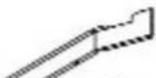
D Metal air guide 1 piece
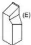
E Rear air guide 1 piece
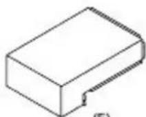
F Upper exhaust guide 1 piece
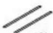
G Black tape strips 2 pieces
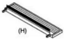
H Bottom grille (with metal strip) 1 piece
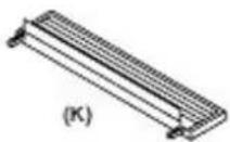
K Top grille 1 piece
L Side trims 2 pieces
M Screws (short) 7 pieces
N Screws (long) 4 pieces
P Paper template 1 piece
See Fig. 2. Also check that all the contents are available before commencing work.
B. Preparing the cupboard for installation
-
Mark the centre of the cabinet shelf. Place the paper template (P) onto the shelf, ensuring that the arrow on the template is on the centreline and flush to the front leading edge of the cabinet shelf.
-
Using a 3mm drill bit, pre-drill the 7 holes marked on the template for attaching the carrier rails and metal air guide. (Fig. 3)
-
Assemble the foam exhaust guide pieces (A) together by interlocking the tab into the hole, to obtain the assembly shown in Fig. 3.
-
Peel the backing strip off the adhesive side of the assembled exhaust guide, then fit it to the cabinet around the back right hand corner of the template (Fig. 3), being careful not to attach to the paper template. When this is done remove the template.
-
Fit the carrier rails (B) onto the cabinet shelf using the 4 small screws (M) provided (Fig. 4).
-
Fit the metal air guide (D) onto the cabinet using the 3 small screws (M) provided (Fig. 4).
-
Fit the adhesive cushion (C) to the upper flange of the metal air guide (D).
N.B. Access will be required to accommodate the plug top/mains cable.
C. Preparing the microwave oven for installation
-
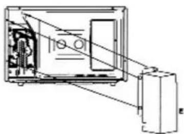
Remove the 3 screws shown in Fig. 5 from the back of the oven. Then use these screws to attach the rear exhaust guide (E) to this area of the oven.
-
Remove the screw at the rear right top of the oven (viewed from behind the oven) (Fig. 6).
-
Hook the Oven exhaust guide (F) into the rear panel of the oven. Secure the Exhaust guide onto the rear panel of the oven using screw removed earlier. Then fit black tape strips (G) to the left and right flanges to seal this part to the top of the microwave oven. See (Fig. 6).
-
Rest the microwave oven on the carrier rails (B). Plug the power cord into the wall mains outlet via hole cut in the back of the cabinet. Ensure that the feet of the oven are located into the recesses.
N.B. Care should be taken when fitting the microwave oven, so as not to pinch the foam pieces and the power cord during installation. Therefore an assistant may be required.
D. Attaching the Plastic Grilles and Side Trims
- Centralise and align the frame pieces to the front of the cabinet and mark the position of the screw holes, and then drill holes using a 3mm drill bit.
- Loosely attach the top and bottom grille pieces (H/K) to the front of the cupboard using the screws (N) provided as shown in (Fig. 7). Ensure that grille piece H is fitted at the bottom.
- Hold the side trim pieces (L) against the oven and align the top and bottom grill vents (H/K). Ensure there is an equal gap between the oven and the trim pieces.
- Tighten up the screws (N).
- Press and clip the side trims (L) into place, between the top and bottom grills on the edge of the cabinet.
E. Removing the Plastic Grills and Side Trims
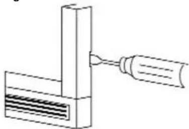
Insert a flat bladed screwdriver into the slot of the side trim pieces (L) and prise them off. See (Fig. 8). Remove the screws fixing the top and bottom grill vent pieces. Ensure that the screwdriver does not slip as to avoid causing damage to the side trim pieces.
- Please read these instructions carefully before you begin
- Electrical Connections
- Contents
- See Fig. 2. Also check that all the contents are available before commencing work.
- Preparing the cupboard for installation
- Preparing the microwave oven for installation
- Attaching the Plastic Grilles and Side Trims
- Removing the Plastic Grills and Side Trims
Brand : Creda
Model : MBC70
Category : Microwave