SKL-70HOA - Air conditioner Maxicool - Free user manual and instructions
Find the device manual for free SKL-70HOA Maxicool in PDF.


| Product Type | Split System Air Conditioner |
| Model | SKL-70HOA |
| Brand | Maxicool |
| Cooling Capacity | 7000 BTU/h |
| Heating Capacity (Heat Pump Models) | 7000 BTU/h |
| Power Supply | 220-240 V ~ 50 Hz, 1 Ph |
| Refrigerant | R410A |
| Control Method | Remote Control (supplied) |
| Modes | Cooling, Heating (on heat pump models), Dry, Fan Only, Sleep, Smart |
| Special Functions | Turbo (Super) Fast Cooling, Swing (Vertical Airflow), Timer (On/Off) |
| Display | Remote LCD with Temperature, Timer, Mode Indicators |
| Air Filter | Washable; Clean every 100 hours or 2 weeks in dusty environments |
| Auto Restart | Configurable via Emergency Button (hold 5 seconds) |
| Protection Features | 3-minute delay on restart, Defrost cycle in heating, Overheat protection |
| Max. Pipe Length | 15 m (additional refrigerant charge required beyond 5 m) |
| Max. Elevation Difference | 5 m |
| Installation Requirements | Dedicated power circuit, Earth leakage circuit breaker recommended |
| Maintenance | Clean front panel with soft dry cloth; do not use volatile substances |
| Safety Notes | Do not repair yourself; ensure proper grounding; keep 1 m from TV/radio |
| Remote Battery | 2 × LR03 AAA (1.5 V); replace when display dims |
| Operating Temperature Range (Cooling) | Outdoor up to 43 °C (52 °C for T3 models) |
| Operating Temperature Range (Heating) | Outdoor -7 °C to 24 °C |
Frequently Asked Questions - SKL-70HOA Maxicool
User questions about SKL-70HOA Maxicool
0 question about this device. Answer the ones you know or ask your own.
Ask a new question about this device
Download the instructions for your Air conditioner in PDF format for free! Find your manual SKL-70HOA - Maxicool and take your electronic device back in hand. On this page are published all the documents necessary for the use of your device. SKL-70HOA by Maxicool.
USER MANUAL SKL-70HOA Maxicool
Preparation before use
Before using the air conditioner, be sure to check and preset the following.
• Remote Controller presetting
• The remote controller is NOT presetting as Cooling Only Air Conditioner or Heat Pump by manufacturer
- Each time after the remote controller replaces batteries or is energized, the Cooling indicator ✝ and Heating indicator ⚙ will flashes alternately on LCD of the remote controller.
- User can preset the remote controller type depending on the air conditioner type you have purchased as follows:
- Press any button when ⚙ flashes, Heat Pump is set.
- Press any button when ✝ flashes, Cooling Only is set.
- If you don't press any button within 12 seconds, the remote controller is preset as Heat Pump automatically.
Note: If the air conditioner you purchased is a Cooling Only one, but you preset the remote controller as Heat Pump, it doesn't bring any matter. But if the air conditioner you purchased is a Heat Pump one, and you preset the remote controller as Cooling Only, then you CAN NOT preset the Heating operation with the remote controller.
• Auto Restart Presetting
The appliance is preset as no auto restart function by manufacturer. If you want auto restart function, let the appliance is energized, hold down the Emergency button (ON/OFF) on the indoor unit for over 5 seconds, auto restart function is set with buzz sound, air conditioner is on standby.
If auto restart has been set, hold down the Emergency button (ON/OFF) on the indoor unit for over 5 seconds, auto restart function is canceled with buzz sound, air conditioner is on standby.
Safety precautions
Symbols in this Use and Care Manual are interpreted as shown below.

Be sure not to do.

The feature of the appliance, instead of a fault.

Pay attention to such a situation.

Be sure to follow this instruction.

Grounding is essential.

Warning: Incorrect handling could cause a serious hazard, such as death, serious injury, etc.
| Use correct power supply in accordance with the rating plate requirement. Otherwise, serious faults or hazard may occur or a fire maybe break out. | 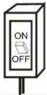 Keep the power supply circuit breaker or plug from dirt. Connect the power supply cord to it firmly and correctly, lest an electric shock or a fire break out due to insufficient contact. Keep the power supply circuit breaker or plug from dirt. Connect the power supply cord to it firmly and correctly, lest an electric shock or a fire break out due to insufficient contact. | 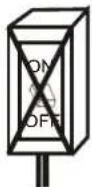 Do not use the power supply circuit breaker or pull off the plug to turn it off during operation. This may cause a fire due to spark, etc. Do not use the power supply circuit breaker or pull off the plug to turn it off during operation. This may cause a fire due to spark, etc. |  |
 Do not knit, pull or press the power supply cord, lest the power supply cord be broken. An electric shock or fire is probably caused by a broken power supply cord. Do not knit, pull or press the power supply cord, lest the power supply cord be broken. An electric shock or fire is probably caused by a broken power supply cord. | 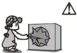 Never insert a stick or similar obstacle to the unit. Since the fan rotates at high speed, this may cause an injury. Never insert a stick or similar obstacle to the unit. Since the fan rotates at high speed, this may cause an injury. |  It is harmful to your health if the cool air reaches you for a long time. It is advisable to let the air flow be deflected to all the room. It is harmful to your health if the cool air reaches you for a long time. It is advisable to let the air flow be deflected to all the room. | |
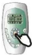 Turn off the appliance by remote control firstly before cutting off power supply if malfunction occurs. Turn off the appliance by remote control firstly before cutting off power supply if malfunction occurs. |  Do not repair the appliance by yourself. If this is done incorrectly, it may cause an electric shock, etc. Do not repair the appliance by yourself. If this is done incorrectly, it may cause an electric shock, etc. |  Prevent the air flow from reaching the gas burners and stove. Prevent the air flow from reaching the gas burners and stove. | |
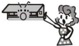 Do not touch the operation buttons when your hands are wet. Do not touch the operation buttons when your hands are wet. |  Do not put any objects on the outdoor unit. Do not put any objects on the outdoor unit. |  It is the user's responsibility to make the appliance be grounded according to local codes or ordinances by a licenced technician. It is the user's responsibility to make the appliance be grounded according to local codes or ordinances by a licenced technician. | |
Identification of parts
Indoor unit

The figures in this manual are based on the external view of a standard model. Consequently, the shape may differ from that of the air conditioner you have selected.
Identification of parts
Operating and Display
"K", "B" and "L" series

flowchart
graph TD
    A["Compressor indicator"] --> B["Timer Indicator"]
    B --> C["Run Indicator"]
    C --> D["Signal Receptor"]
    D --> E["Emergency button"]

    style A fill:#f9f,stroke:#333
    style B fill:#ccf,stroke:#333
    style C fill:#cfc,stroke:#333
    style D fill:#fcc,stroke:#333
    style E fill:#cff,stroke:#333

    note1["It lights up when compressor is running."] -.-> A
    note2["It lights up during the set time."] -.-> B
    note3["It is on during operation. It flashes during defrosting."] -.-> C
    note4["Receive signal from the remote controller."] -.-> D
    note5["Used to control the unit when the remote controller is out of work. Used to set or cancel auto restart function. (See page 1)"]
"N" series

Other series

flowchart
graph TD
    A["Emergency button"] --> B["Compressor indicator"]
    B --> C["Timer Indicator(Yellow)"]
    C --> D["Run Indicator (Green)"]
    D --> E["Signal Receptor"]
    style A fill:#f9f,stroke:#333
    style B fill:#ccf,stroke:#333
    style C fill:#cfc,stroke:#333
    style D fill:#fcc,stroke:#333
    style E fill:#cff,stroke:#333
The shape and position of the switches and indicators may vary from different models, but their function are similar.
Remote controller
Remote controller
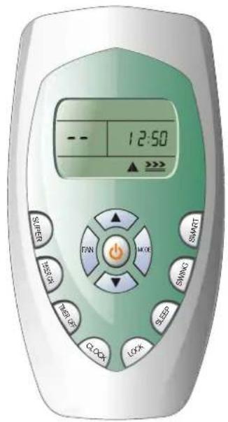
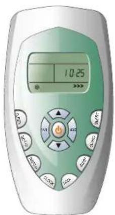
The remote controller transmits signals to the system.
1 ON/OFF BUTTON
The appliance will be started when it is energized or will be stopped when it is in operation, if you press this button.
2 MODE BUTTON
Press this button to select the operation mode.
3 FAN BUTTON
Used to select fan speed in sequence auto, high, medium or low.
4 5 ROOM TEMPERATURE SETTING BUTTONS
Used to adjust the room temperature and the timer, also real time.
6 SMART BUTTON
Used to enter fuzzy logic operation directly, regardless of the unit is on or off.
7 SWING BUTTON
Used to stop or start vertical adjustment louver swinging and set the desired up/down airflow direction.
8 SLEEP BUTTON
Used to set or cancel Sleep Mode operation.
9 LOCK BUTTON
When you press this button, all the buttons are locked and not available. Press again to cancel it.
10 CLOCK BUTTON
Used to set the current time.
11 12 TIMER ON/OFF BUTTON
Used to set or cancel the timer operation.

SUPER BUTTON
Used to start or stop the fast cooling. (Fast cooling operates at high fan speed with 18^ C set temp automatically)
Indication symbols on LCD:

Cooling indicator

Auto fan speed Smart indicator

Signal transmit.

Dry indicator

High fan speed

Sleep indicator

88:88
Display set timer
Display current time

Fan only indicator

Medium fan speed

Lock indicator

Heating indicator

Low fan speed

Super indicator

Display set temperature
Note: Each mode and relevant function will be further specified in following pages.
Remote controller
Remote controller
• How to Insert the Batteries
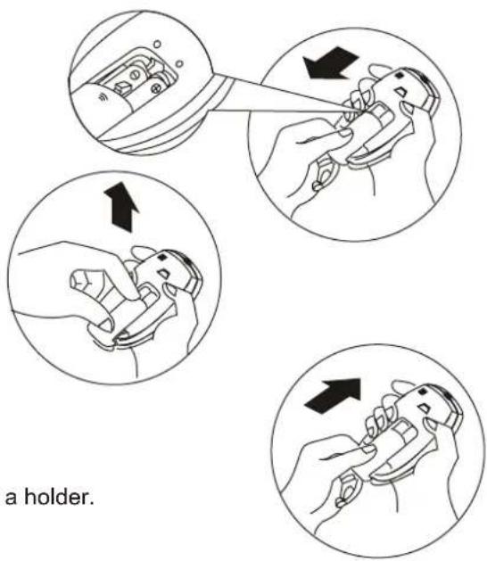
Remove the battery cover according to the arrow direction. Insert new batteries making sure that the (+) and (-) of battery are matched correctly.
Reattach the cover by sliding it back into position.
Note:
- Use 2 LR03 AAA(1.5volt) batteries. Do not use rechargeable batteries. Replace batteries with new ones of the same type when the display becomes dim.
- If the replacement is done within 1 minute, the remote controller will keep original presetting. However, if you want to change the presetting from Heat Pump to Cool Only or Cool Only to Heat Pump, you should reload batteries 3 minutes after removing the old ones. (Please refer to page 1 for details.)
• Storage and Tips for Using the Remote Controller
The remote controller may be stored mounted on a wall with a holder.
Note: The remote controller holder is an optional part.

flowchart
graph TD
    A["Person using tool"] --> B["Device with digital display"]
    B --> C["Device with remote control"]
    C --> D["Device with heat pump"]
    D --> E["Signal receptor"]
• How to Use
To operate the room air conditioner, aim the remote controller to the signal receptor. The remote controller will operate the air conditioner at a distance of up to 7m when pointing at signal receptor of indoor unit.
- Choose Cooling Only Remote controller or Heat Pump
Please refer to page 1 "Preparation before use" for details.
Operation instructions
Operation modes
Selecting mode
Each time MODE button is pressed, the operation mode is changed in sequence:

flowchart
graph LR
    A["COOLING"] --> B["DRY"]
    B --> C["FAN ONLY"]
    C --> D["HEATING"]
Heating mode is NOT available for cooling only air conditioner.
FAN mode
Each time the "FAN" button is pressed, the fan speed is changed in sequence:

At "FAN ONLY" mode, only "High", "Medium" and "Low" are available. At "DRY" mode, Fan speed is set at "Low" automatically, "FAN" button is ineffective in this case.
Setting temperature

Press once to temperature setting by 1raise°C

Press once to temperature setting by 1lower°C


| Range of available set temperature | |
| *HEATING, COOLING | 18°C32 °C |
| DRY | unable to set |
| FAN ONLY | unable to set |
*Note: Heating mode is NOT available for cooling only models.
Turning on
Press 🔍 button, when the appliance receives the signal, the RUN indicator of the indoor unit lights up.

SWING, SMART, TIMER ON, TIMER OFF, CLOCK, SLEEP and SUPER operation modes will be specified in the following pages.
- Changing modes during operation, sometimes the unit does not response at once. Wait 3 minutes.
- During heating operation, air flow is not discharged at the beginning. After 2–5 minutes, the air flow will be discharged until temperature of indoor heat exchanger rises.
- Wait 3 minutes before restarting the appliance.
Operation instructions
Airflow direction control
Airflow direction control
Vertical airflow is automatically adjusted to a certain angle in accordance with the operation mode after turning on the unit.
| Operation mode | Direction of airflow |
| COOLING, DRY | horizontal |
| *HEATING, FAN ONLY | downward |
The direction of airflow can be also adjusted to your own requirement by pressing the "SWING" button of the remote controller.

*Heating mode is only available for heat pump models.

Vertical airflow control (with the remote controller)
Using remote controller to set various angles of flow or specific angle as you like.
Swinging airflow
Pressing "SWING" button once, the vertical adjustment louver will swing up and down automatically.
Desired direction airflow
Pressing the "SWING" button again when the louvers swing to a suitable angle as desired.
Horizontal airflow control (with hands)
Turning the control rods of the horizontal adjustment louvers to change horizontal air flow as shown.
Note: The shape of the unit may look different from that of the air conditioner you have selected.

natural_image
Line drawing of a wall-mounted air conditioner unit with hands adjusting its buttons (no text or symbols)control rods of horizontal adjustment louvers

A Do not turn the vertical adjustment louvers manually, otherwise malfunction may occur. If that happens, turn off the unit first and cut off the power supply, then restore power supply again.
B It is better not to let the vertical adjustment louver tilt downward for a long time at COOLING or DRY mode to prevent condensed water from dripping.
Operation instructions
SMART mode
Press the SMART button, the unit enters SMART mode(fuzzy logic operation) directly regardless of the unit is on or off. In this mode, temperature and fan speed are automatically set based on the actual room temperature.
Operation mode and temperature are determined by indoor temperature
Heat pump models
| Indoor temperature | Operation mode | Target temperature |
| 21°C or below | HEATING | 22°C |
| 21°C 23 °C | FAN ONLY | |
| 23°C -26°C | DRY | Room temperature decrease 1.5°C after operate for 3 minutes |
| Over 26°C | COOLING | 26°C |
Cooling only models
| Indoor temperature | Operation mode | Target temperature |
| 26°C or below | DRY | Room temperature decrease 1.5° after operate for 3 minutes |
| Over 26°C | COOLING | 26°C |
SMART button is ineffective in SUPER mode.
Note: Temperature, airflow and direction are controlled automatically in 6th mode. However, a decrease or rise of up to 2 ° can be set with the remote controller if you still feel uncomfortable.
| What you can do in SMART mode | ||
| Your feeling | button | adjustment procedure |
| Uncomfortable because of unsuitable air flow volume. | [K347] | Indoor fan speed alternates among High, Medium and Low each time this button is pressed. |
| Uncomfortable because of unsuitable flow direction. | [W038] | Press it once, the vertical adjustment louver swings to change vertical airflow direction. Press it again, swings stops. For horizontal airflow direction, please refer to the previous page for details. |
CLOCK button
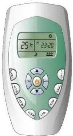
You can adjust the real time by pressing CLOCK button, then using 🔒 and ▼ buttons to get the correct time, press CLOCK button again the real time is set.

Operation instructions
Timer mode
It is convenient to set the timer on with TIMER ON/OFF buttons when you go out in the morning to achieve a comfortable room temperature at the time you get home. You can also set timer off at night to enjoy a good sleep.
▶ How to set TIMER ON
TIMER ON button can be used to set the timer programming as wished in order to switch on the appliance at your desired time.
i) Press TIMER ON button, "ON 12:00" flashes on the LCD, then you can press the 🔊 or ▼ buttons to select your desired time for appliance on.


Press the TIMER ON button once to increase or decrease the time setting by 1 minute.
Press the TIMER ON button one and a half seconds to increase or decrease the time setting by 10 minute.
Press the TIMER ON button for a longer time to increase or decrease the time by 1 hour.
Note: If you don't set the time in 10 seconds after you press TIMER ON button, the remote controller will exit the TIMER ON mode automatically.
ii) When your desired time displayed on LCD, press the TIMER ON button and confirm it.
A "beep" can be heard.
"ON" stops flashing.
The TIMER indicator on the indoor unit lights up.
iii) After the set timer displayed for 5 seconds the clock will be displayed on the LCD of the remote controller instead of set timer.
▶ How to cancle TIMER ON
Press the TIMER ON button again, a "beep" can be heard and the indicator disappears, the TIMER ON mode has been canceled.
Note: It is similar to set TIMER OFF, you can make the appliance switch off automatically at your desired time.
Operation instructions
SLEEP mode
SLEEP mode
SLEEP mode can be set in COOLING or HEATING operation mode.
This function gives you a more comfortable environment for sleep.
In SLEEP mode,
- The appliance will stop operation automatically after operating for 8 hours.
- Fan speed is automatically set at low speed.
*Set temperature will rise by 1 °f thermoppliance operates in cooling mode for 2 hours constantly, then keeps steady. - Set temperature will decrease by 3°C at most if the appliance operates in heating mode for 3 hours constantly, then keeps steady.
*Note: In cooling mode, if room temperature is 26° or above, set temperature will not change.
Note: Heating is NOT available for cooling only air conditioner.
- SUPER mode is used to start or stop fast cooling.
Fast cooling operates at high fan speed, changing the set temperature automatically to 18°C - SUPER mode can be set when the appliance is in operation or energized.
- In SUPER mode, you can set airflow direction or timer. If you want to escape from SUPER mode, press any - SUPER, MODE, FAN, ON/OFF or TEMPERATURE SETTING button, the display will return to the original mode.
Note:
•SLEEP and SMART buttons are not available in SUPER mode.
- SUPER button is ineffective in HEATING mode.
- The Appliance will continue working in SUPER mode with set temperature of 18^ , if you don't escape from it by pressing any of the buttons mentioned above..
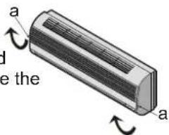
Front panel maintenance Air fil

Cut off the power supply


Grasp position "a" and pull outward to remove the front panel.

Wipe with a soft and dry cloth.
Use lukewarm water (below 40°C) to clean if the appliance is very dirty.
Use a dry and soft cloth to clean it.

Never use volatile substance such as gasoline or polishing powder to clean the appliance.


Never sprinkle water onto the indoor unit


Reinstall and shut the front panel.
Reinstall and shut the front panel by pressing position "b" downward.

tenance
It is necessary to clean the air filter after using it for about 100 hours.
Clean it as follows:

Stop the appliance and remove the air filter.

1.Open the front panel.
2. Press the handle of the filter gently from the front.
3. Grasp the handle and slide out the filter.

Clean and reinstall the air filter.
If the dirt is conspicuous, wash it with a solution of detergent in lukewarm water. After cleaning, dry well in shade.

natural_image
Illustration of a person holding a photo album with multiple small images (no text or symbols visible)
Close the front panel again.
√ Clean the air filter every two weeks if the air conditioner operates in an extremely dusty environment.
Protection
Operating condition
The protective device maybe trip and stop the appliance in the cases listed below.
| HEATING | Outdoor air temperature is over 24 ^ C |
| Outdoor air temperature is below -7 ^ C | |
| Room temperature is over 27 ^ C | |
| COOLING | Outdoor air temperature is over *43 ^ C |
| Room temperature is below 21 ^ C | |
| DRY | Room temperature is below 18 ^ C |
*For Tropical (T3) Climate condition models, the temperature point is 52°C instead of 43°C
If the air conditioner runs in COOLING or DRY mode with door or window opened for a long time when relative humidity is above 80%, dew may drip down from the outlet.
Noise pollution
• Install the air conditioner at a place that can bear its weight in order to operate more quietly.
• Install the outdoor unit at a place where the air discharged and the operation noise would not annoy your neighbors.
- Do not place any obstacles in front of the air outlet of the outdoor unit lest it increases the noise level.
Features of protector
1 The protective device will work at following cases.
- Restarting the unit at once after operation stops or changing mode during operation, you need to wait 3 minutes.
-
Connect to power supply and turn on the unit at once, it may start 20 seconds later.
-
If all operation has stopped, press ON/OFFbutton again to restart, Timer should be set again if it has been canceled.
Features of HEATING mode
Preheat
At the beginning of HEATING operation, the airflow from indoor unit is discharged 2-5 minutes later.
Defrost
In HEATING operation the appliance will defrost (de-ice) automatically to raise efficiency. This procedure usually lasts 2-10 minutes. During defrosting, fans stop operation. After defrosting completes, it returns to HEATING mode automatically.
Note: Heating is NOT available for cooling only air conditioner models.
Troubleshooting
The following cases may not always be a malfunction, please check it before asking for service.
| Trouble Analysis | ||
| Does not run | 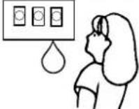 | If the protector trip or fuse is blown.Please wait for 3 minutes and start again, protector device may be preventing unit to work.If batteries in the remote controller exhausted.If the plug is not properly plugged. |
| No cooling or heating air |  | Is the air filter dirty?Are the intakes and outlets of the air conditioner blocked?Is the temperature set properly? |
| Ineffective control |   | If strong interference(from excessive static electricity discharge, power supply voltage abnormality)presents, operation will be abnormal. At this time, disconnect from the power supply and connect back 2-3 seconds later. |
| Does not operate immediately |  | Changing mode during operation, 3 minutes will delay. |
| Peculiar odor |  | This odor may come from another source such as furniture, cigarette etc, which is sucked in the unit and blows out with the air. |
| A sound of flowing water |   | Caused by the flow of refrigerant in the air conditioner, not a trouble.Defrosting sound in heating mode. |
| Cracking sound is heard |   | The sound may be generated by the expansion or contraction of the front panel due to change of temperature. |
| Spray mist from the outlet |  | Mist appears when the room air becomes very cold because of cool air discharged from indoor unit during COOLING or DRY operation mode. |
| The compressor indicator(red) lights on constantly, and indoor fan stops. | The unit is shifting from heating mode to defrost. The indicator will lights off within ten minutes and returns to heating mode. | |
Installation instructions
Installation diagram

Installation instructions
Select the best location
Location for Installing Indoor Unit
- Where there is no obstacle near the air outlet and air can be easily blown to every corner.
• Where piping and wall hole can be easily arranged. - Keep the required space from the unit to the ceiling and wall according to the installation diagram on previous page.
• Where the air filter can be easily removed. - Keep the unit and remote controller 1m or more apart from television, radio etc.
• To prevent the effects of a fluorescent lamps, keep as far as possible. - Do not put anything near the air inlet to obstruct it from air absorption.
- Where there is strong enough to bear the weight and is not tend to increase operation noise and vibration.

Location for Installing Outdoor Unit
- Where it is convenient to install and well ventilated.
- Avoid installing it where flammable gas could leak.
- Keep the required distance apart from the wall.
- The distance between Indoor and outdoor unit should be 5 meters and can go up to maximum 15 meters with additional refrigerant charge.
- Keep the outdoor unit away from a place of greasy dirt, vulcanization gas exit.
- Avoid installing it at the roadside where there is a risk of muddy water.
- A fixed base where is not subject to increasing operation noise.
- Where there is not any blockage for air outlet.

| Model | Max. Allowable Tubing Length at Shipment (m) | Limit of Tubing Length (m) | Limit of Elevation Difference H (m) | Required amount of additional refrigerant (g/m) |
| 7K~24K 5 | 15 5 20 |
Installation instructions
Indoor unit installation
1. Installing the Mounting Plate
- Decide an installing location for the mounting plate according to the indoor unit location and piping direction.
- Keep the mounting plate horizontally with a horizontal ruler or dropping line.
- Drill holes of 32mm in depth on the wall for fixing the plate.
- Insert the plastic plugs to the hole, fix the mounting plate with tapping screws.
- Inspect if the mounting plate is well fixed. Then drill a hole for piping.

Note: The shape of your mounting plate may be different from the one above, but installation method is similar.
2. Drill a Hole for Piping
- Decide the position of hole for piping according to the location of mounting plate.
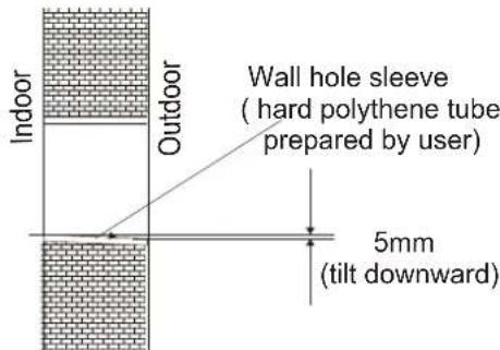
- Drill a hole on the wall. The hole should tilt a little downward toward outside.
• Install a sleeve through the wall hole to keep the wall tidy and clean.
3. Indoor Unit Piping Installation
- Put the piping (liquid and gas pipe) and cables through the wall hole from outside or put them through from inside after indoor piping and cables connection complete so as to connect to outdoor unit.
- Decide whether saw the unloading piece off in accordance with the piping direction.(as shown below)

Note: When installing the pipe at the directions 1,2 or 4, saw the corresponding unloading piece off the indoor unit base.
- After connecting piping as required, install the drain hose. Then connect the power cords. After connecting, wrap the piping, cords and drain hose together with thermal insulation materials.
Installation instructions

- Piping Joints Thermal Insulation: Wrap the piping joints with thermal insulation materials and then wrap with a vinyl tape.

natural_image
Pure mechanical cross-section diagram without any text, numbers, or symbols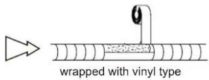
Thermal insulation
- Piping Thermal Insulation:
a. Place the drain hose under the piping. b. Insulation material uses polythene foam over 6mm in thickness. Note: Drain hose is prepared by user.
- Drain pipe should point downward for easy drain flow. Do not arrange the drain pipe twisted, sticking out or wave around, do not immerse the end of it in water.
If an extension drain hose is connected to the drain pipe, make sure to thermal insulated when passing along the indoor unit.
- When the piping is directed to the right, piping, power Cord and drain pipe should be thermal insulated and fixed onto the back of the unit with a piping fixer.


A. Insert the pipe fixer to the slot.


B. Press to hook the pipe fixer onto the base.
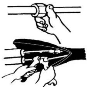
Piping Connection:
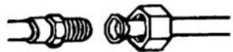
a. Connect indoor unit pipes with two wrenches. Pay special attention to the allowed torque as shown below to prevent the pipes, connectors and flare nuts from being deformed and damaged.
b. Pre-tighten them with fingers at first, then use the wrenches.
| Pipe sizeMod | Tbrque Nut width | Min.thickness | ||
| Liquid Side (1/4 inch) | 7.9kg.m | 17mm | 0.6mm | |
| 22,24K | Liquid Side (3/8 inch) | 3.5kg.m | 22mm | 0.6mm |
| 7,9K | Gas Side (3/8 inch) | 3.5kg.m | 22mm | 0.6mm |
| 12,18K | Gas Side (1/2 inch) | 5.5kg.m | 24mm | 0.6mm |
| 22,24K | Gas Side (5/8 inch) | 7.5kg.m | 27mm | 0.6mm |
If refrigerant of the appliance is R407C or R410A, 18K Liquid Side is ( 0 or 3/8 inch), and Gas side is (16 or 5/8 inch).
For T3 climate kind models, 18K and 24K Liquid Side is (φor 1/4 inch).
natural_image
Illustration of hands performing a manual tool manipulation (no text or symbols present)Installation instructions
4. Connecting of the Cable
- Indoor Unit
Connect the power connecting cord to the indoor unit by connecting the wires to the terminals on the control board individually in accordance with the outdoor unit connection.
Note: For some models, it is necessary to remove the cabinet to connect to indoor unit terminal.
- Outdoor Unit
1). Remove the access door from the unit by loosening the screw. Connect the wires to the terminals on the control board individually as the following.
2). Secure the power connecting cord onto the control board with cable clamp.
3). Reinstall the access door to the original position with the screw.
4) Use a recognized circuit breaker for 24K model between the power source and the unit. A disconnecting device to adequately disconnect all supply lines must be fitted.

Caution:
- Never fail to have an individual power circuit specifically for the air conditioner. As for the method of wiring, refer to the circuit diagram posted on the inside of the access door.
- Confirm that the cable thickness is as specified in the power source specification. (See the cable specification table below)
- Check the wires and make sure that they are all tightly fastened after cable connection.
- Be sure to install an earth leakage circuit breaker in wet or moist area.
Cable Specifications
| Capacity (Btu/h) | Power cord | Power connecting cord | Power connecting cord1 (for heat pump) | Delayed fuse | |||
| Type | Normal cross - sectional area | Type | Normal cross - sectional area | Type | Normal cross - sectional area | ||
| 7K,9K H07RN-FH05VV-F1.0mm2X3 | 1.5mm2X3 | H07RN-F | 0.75mm2X2 | 15A | |||
| 12K | H05VV-F | 1.5mm2X3 | H07RN-F | H07R5mm2X3 | 0.75mm2X2 | 15A | |
| 18K | H05VV-F | 2.0mm2X3 | H07RN-F | H07R5mm2X3 | 0.75mm2X2 | 20A | |
| 22K | H05VV-F | 2.0mm2X3 | H07RN-F | H07R5mm2X3 | 0.75mm2X2 | 20A | |
| 24K | 2.5mm2X3 | H07RN-F | 1.5mm2X3(heat pump)1.5mm2X4(cool only) | 0.75mm2X3 | 20A | ||
Attention:
Accessibility to the plug must be guaranteed even after the installation of the appliance to disconnect it in case of need. If not possible, connect appliance to a double-pole switching device with contact separation of at least 3 mm placed in an accessible position even after installation.
Installation instructions
Wiring Diagram
Make sure that the color of wires of the outdoor unit and the terminal No. are the same as those of the indoor unit.
• 7K,9K,12K,18K,22K Model
HEAT PUMP
Indoor unit Indoor unit
Outdoor unit Outdoor unit
COOLING ONLY
TerminalTerminalTerminal


For above models, the power supply are connected from indoor unit, with a plug.
• 24K Model
For 24K model, the power supply are connected from outdoor unit, with a circuit breaker. Other models from indoor unit.)

flowchart
graph TD
    subgraph "COOLING ONLY"
        direction TB
        A["1L"] --> B["Orange"]
        C["L"] --> D["Brown"]
        E["N"] --> F["Blue"]
        G["Terminal"] --> H["Yellow/Green"]
        I["Terminal"] --> J["Power supply"]
    end
    subgraph "INDOOR UNIT"
        K["3L"] --> L["Orange"]
        M["2L"] --> N["Black"]
        O["1L"] --> P["Brown"]
        Q["L"] --> R["Blue"]
        S["N"] --> T["Yellow/Green"]
        U["Terminal"] --> V["Power supply"]
    end
    style A fill:#f9f,stroke:#333
    style C fill:#f9f,stroke:#333
    style O fill:#f9f,stroke:#333
    style Q fill:#f9f,stroke:#333
    style S fill:#f9f,stroke:#333
    style U fill:#f9f,stroke:#333
    style I fill:#f9f,stroke:#333
    style J fill:#f9f,stroke:#333
    style K fill:#ccf,stroke:#333
    style L fill:#ccf,stroke:#333
    style M fill:#ccf,stroke:#333
    style N fill:#ccf,stroke:#333
    style O fill:#ccf,stroke:#333
    style P fill:#ccf,stroke:#333
    style Q fill:#ccf,stroke:#333
    style R fill:#ccf,stroke:#333
    style S fill:#ccf,stroke:#333
    style T fill:#ccf,stroke:#333
    style U fill:#ccf,stroke:#333
    style V fill:#ccf,stroke:#333
• Defrost Cable (for heat pump air conditioner only)

After connection, the defrost wire should be well wrapped with a wrapping tape and the the connector should be put inside the unit.
Installation instructions
Outdoor unit installation
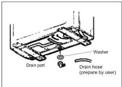
1. Install Drain Port and Drain Hose (for heat-pump model only)
The condensate drains from the outdoor unit when the unit operates in heating mode. In order not to disturb your neighbor and protect the environment, install a drain port and a drain hose to direct the condensate water. Just install the drain port and rubber washer to the chassis of the outdoor unit, then connect a drain hose to the port as the right figure shown.
2. Install and Fix Outdoor Unit
Fix with bolts and nuts tightly on a flat and strong floor.
If installed on the wall or roof, make sure to fix the supporter well to prevent it from shaking due to serious vibration or strong wind.
3. Outdoor Unit Piping Connection
- Remove the valve caps from the 2-way and 3-way valve.
- Connect the pipes to the 2-way and 3-way valves separately according to the required torque.
4. Outdoor Unit Cable Connection (see previous page)
Air purging
The air which contains moisture remaining in the refrigeration cycle may cause a malfunction on the compressor. After connecting the indoor and outdoor units, evacuate air and moisture from refrigerant cycle using a vacuum pump, as shown below.
Note: To protect the environment, be sure not to discharge the refrigerant to the air directly. See next page for air purging steps.

flowchart
graph TD
    A["Vacuum pump"] --> B["Indoor unit"]
    B --> C["Refrigerant flow direction"]
    C --> D["3-way valve"]
    D --> E["2-way valve"]
    E --> F["Valve cap"]
    F --> G["Turn to fully open the valve"]
    G --> H["Service port"]
    G --> I["Tighten"]
    H --> J["Valve core"]
    I --> K["Tighten"]
    L["3-way valve diagram"] --> M["Connect to indoor unit"]
    M --> N["open position"]
    M --> O["spindle"]
    M --> P["needle"]
    M --> Q["service port cap"]
    style A fill:#f9f,stroke:#333
    style L fill:#ccf,stroke:#333
    style M fill:#cfc,stroke:#333
Installation instructions
How to Purge Air Tubes:
(1). Unscrew and remove caps from 2 and 3-way valves.
(2). Unscrew and remove cap from service valve.
(3). Connect vacuum pump flexible hose to the service valve.
(4). Start vacuum pump for 10-15 minutes until reaching a vacuum of 10 mm Hg absolutes.
(5). With vacuum pump still running close the low pressure knob on vacuum pump manifold. Then stop vacuum pump.
(6). Open 2-way valve 1/4 turn then close it after 10 seconds. Check tightness of all joints using liquid soap or an electronic leak detector.
(7). Turn 2 and 3-way valves stem to fully the valves. Disconnect vacuum pump flexible hose.
(8). Replace and tighten all valve caps.
Notes
- Please read this manual before installing and using it.
- Do not let air enter the refrigeration system or discharge refrigerant when moving the air conditioner.
- Testing run the air conditioner after finishing installation, and record details of operation.
- Type of fuse used on indoor unit controller is 50T, with rating 2.5A, AC250V.
- The fuse for the whole unit is to be provided by the user according to the current at maximum power Input or use other over-current protective device instead.
- Only the air conditioner can be connected to the power line.
- The power connection for the air conditioner has to be done at the main power distribution which has to be of a low impedance.
- In order to ensure the suitability of the equipment for connection, the user should consult with the supply authority, if necessary, that the service current capacity at the interface point is sufficient for the equipment.
• Refer to the rating plate of the equipment for power consumption details.
- If the supply cord is damaged, it must be replaced by the manufacturer or its service agent or similarly qualified person in order to avoid a hazard.

- When charging refrigerant into the system, make sure to charge in liquid state, if refrigerant of the appliance is R407c or R410A. Otherwise, chemical composition of refrigerant (R407c or R410A) inside the system may change and thus affect performance of the air conditioner.
- According to the character of refrigerant (R410A), the pressure of the tube is very high, so be sure to careful when you install and repair the appliance.
- Preparation before use
- Safety precautions
- Identification of parts
- Operating and Display
- Remote controller
- ON/OFF BUTTON
- MODE BUTTON
- FAN BUTTON
- 5 ROOM TEMPERATURE SETTING BUTTONS
- SMART BUTTON
- SWING BUTTON
- SLEEP BUTTON
- LOCK BUTTON
- CLOCK BUTTON
- 12 TIMER ON/OFF BUTTON
- SUPER BUTTON
- Indication symbols on LCD:
- • How to Insert the Batteries
- • Storage and Tips for Using the Remote Controller
- • How to Use
- - Choose Cooling Only Remote controller or Heat Pump
- Operation instructions
- Operation modes
- Selecting mode
- FAN mode
- Setting temperature
- Turning on
- Airflow direction control
- Vertical airflow control (with the remote controller)
- Swinging airflow
- Desired direction airflow
- Horizontal airflow control (with hands)
- SMART mode
- CLOCK button
- Timer mode
- ▶ How to set TIMER ON
- ▶ How to cancle TIMER ON
- SLEEP mode
- Front panel maintenance Air fil
- tenance
- Protection
- Operating condition
- Noise pollution
- Features of protector
- Features of HEATING mode
- Preheat
- Defrost
- Troubleshooting
- Installation instructions
- Select the best location
- Location for Installing Indoor Unit
- Location for Installing Outdoor Unit
- Indoor unit installation
- Installing the Mounting Plate
- Drill a Hole for Piping
- Indoor Unit Piping Installation
- Piping Connection:
- Connecting of the Cable
- - Indoor Unit
- - Outdoor Unit
- Caution:
- Attention:
- Outdoor unit installation
- Install Drain Port and Drain Hose (for heat-pump model only)
- Install and Fix Outdoor Unit
- Outdoor Unit Piping Connection
- Outdoor Unit Cable Connection (see previous page)
- Air purging
- How to Purge Air Tubes:
- Notes
Brand : Maxicool
Model : SKL-70HOA
Category : Air conditioner