Bogen MVP130BG - Telephone

MVP130BG - Telephone Bogen - Free user manual and instructions

Find the device manual for free MVP130BG Bogen in PDF.

📄 12 pages English EN Download 💬 AI Question 10 questions ⚙️ Specs
Notice Bogen MVP130BG - page 2
Pick your language and provide your email: we'll send you a specifically translated version.
Product Type Telephone Paging Interface
Brand Bogen
Model MVP130BG
Dimensions (W x H x D) 4.25 x 1.75 x 6.5 inches (108 x 44 x 165 mm)
Weight 1.2 lbs (0.54 kg)
Power Requirements 24 VDC, 200 mA (provided via included power supply)
Audio Output 1.5W RMS into 8 ohms
Input Sensitivity Adjustable, 0-100 mV
Frequency Response 300 Hz – 3.4 kHz (telephone bandwidth)
Number of Lines 1 telephone line (RJ11)
Paging Trigger Contact closure or DTMF
Page Output Balanced line-level (remove pluggable terminal block)
Operation Automatic page on incoming ring or manual DTMF command
Mounting Wall-mountable or desk use with included brackets
LED Indicators Power, Page Active, Line In Use
Control Volume adjust, page sensitivity, line impedance settings
Enclosure Material Steel with black powder coat finish
Safety Certifications FCC Part 15, UL listed
Operating Temperature 32°F to 104°F (0°C to 40°C)
Included Accessories Power supply, RJ11 cable, mounting hardware, user manual

Frequently Asked Questions - MVP130BG Bogen

What power supply is required for the Bogen MVP130BG?
The MVP130BG requires a 24 VDC power supply with a minimum of 200 mA. A compatible power supply is included with the unit.
Can I use the MVP130BG with any telephone system?
It works with standard analog telephone lines (POTS) and most PBX extensions. For digital systems, you may need an appropriate analog adapter.
How does the MVP130BG trigger a page?
The unit can trigger a page automatically when an incoming ring is detected, or manually by sending a DTMF code from any phone on the line.
What is the maximum output power for paging?
The built-in amplifier provides 1.5W RMS into an 8-ohm speaker. For larger areas, use the line-level output to connect an external amplifier.
Is the MVP130BG compatible with overhead paging systems?
Yes, the line-level balanced output can feed into most commercial paging amplifiers and 70V or 25V speaker systems.
How do I adjust the microphone/speaker volume?
Use the volume control on the front panel. There is also an internal trim pot for fine-tuning the page sensitivity.
Can I connect multiple MVP130BG units together?
Yes, multiple units can be daisy-chained using the line-level outputs to cover different zones from a single telephone line.
What do the LED indicators mean?
The Power LED stays on when connected. Page Active lights during a page. Line In Use shows the telephone line is busy.
How do I reset the MVP130BG to factory defaults?
There is no reset button; adjust the dip switches and pots inside the unit to the factory positions as described in the manual.
Is technical support available for the MVP130BG?
Bogen provides free technical support by phone and online. You can also find FAQs and manuals on their website.

User questions about MVP130BG Bogen

0 question about this device. Answer the ones you know or ask your own.

Ask a new question about this device

The email remains private: it is only used to notify you if someone responds to your question.

No questions yet. Be the first to ask one.

Download the instructions for your Telephone in PDF format for free! Find your manual MVP130BG - Bogen and take your electronic device back in hand. On this page are published all the documents necessary for the use of your device. MVP130BG by Bogen.

USER MANUAL MVP130BG Bogen

This publication may not be reproduced, in whole or in part, without prior expressed written permission from Multi-Tech Systems, Inc. All rights reserved.

Copyright © 2004, by Multi-Tech Systems, Inc.

Multi-Tech Systems, Inc. makes no representations or warranties with respect to the contents hereof and specifically disclaims any implied warranties of merchantability or fitness for any particular purpose.

Furthermore, Multi-Tech Systems, Inc. reserves the right to revise this publication and to make changes from time to time in the content hereof without obligation of Multi-Tech Systems, Inc. to notify any person or organization of such revisions or changes.

Record of Revisions

Revision Description

A Initial Release. (01/07/04)

B Additional application changes (02/16/04)

C Add Caution for Low Power (2/24/04)

Patents

This Product is covered by one or more of the following U.S. Patent Numbers: 6151333, 5757801, 5682386, 5.301.274; 5.309.562; 5.355.365; 5.355.653; 5.452.289; 5.453.986. Other Patents Pending.

Trademark

Trademark of Multi-Tech Systems, Inc. is the Multi-Tech logo. Windows is a registered trademark of Microsoft.

Multi-Tech Systems, Inc.

2205 Woodale Drive

Mounds View, Minnesota 55112

(763) 785-3500 or (800) 328-9717

U.S. Fax: 763-785-9874

Technical Support: (800) 972-2439

http://www.multitech.com

Bogen paging example using FXS Pass Through feature.

The example below shows a Bogen PCM/ZPM Zone Paging unit at the Corporate site connected through MultiVOIPs to amplifiers and speakers at each of two branch sites. Users at the corporate site can page users at the Branch A and/or Branch B sites.

The FXS Pass Through feature allows an “always on” audio connection to exist between the Corporate site and both Branch A and Branch B sites. The MultiVOIPs use of Silence Compression means little or no bandwidth is used when not paging.

Bogen MVP130BG - Trademark - 1

flowchart
graph TD
    A["Corporate PBX"] -->|CAUTION Set PCMZPM output selector switch to Low Power| B["MVP210-BG"]
    B -->|Zone A| C["MultiTech System"]
    B -->|Zone B| D["MVP210-BG"]
    B -->|FXS Ch1| E["MVP130-BG"]
    B -->|FXS Ch2| F["MVP130-BG"]
    E --> G["Branch A"]
    F --> H["Branch B"]
    I["Internet"] --> J["MVP130-BG"]
    I --> K["MVP130-BG"]
    J --> L["Branch A"]
    K --> M["Branch B"]

Figure 1. Bogen paging system diagram.

  1. Preliminary planning: Determine the number of MultiVOIP gateways to be used for the paging network. Assign a unique IP address and identifying number to each MultiVOIP. It is helpful to write this down like below:
MultiVOIP NameIdentifying NumberIP Address Local Voice ChannelDestination MultiVOIP NumberDestination MultiVOIP Voice Channel
Corporate 192.168.25.20 12 1
23
Branch A 292.168.25.21 11 1
Branch B 392.168.25.22 11 2
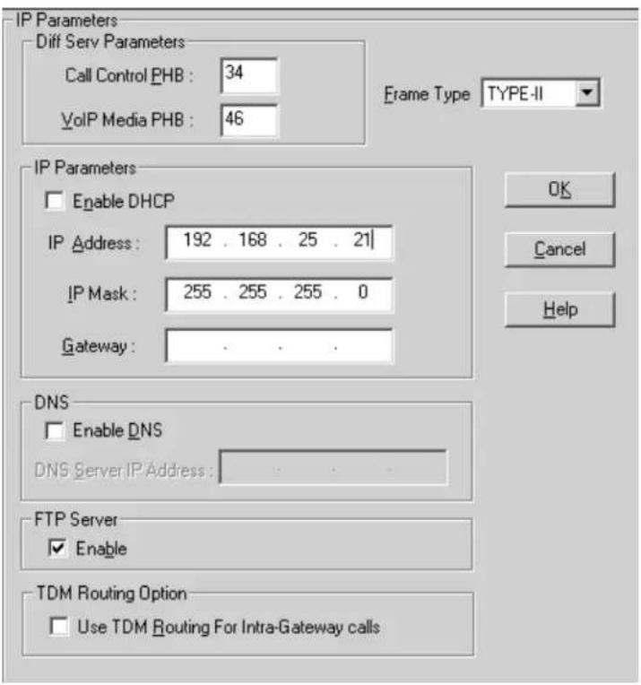
  1. In the Configuration / IP screen of the MultiVOIP Configuration software, configure each MultiVOIP with a unique IP address. Also configure the mask and gateway address. If all MultiVOIPs are located in the same subnet, you can leave the gateway address field blank. Click Ok when finished.

IP Parameters Diff Serv Parameters Call Control PHB : 34 VoIP Media PHB : 46 Frame Type TYPE-II IP Parameters Enable DHCP IP Address : 192 . 168 . 25 . 20 IP Mask : 255 . 255 . 255 . 0 Gateway : 1 . . . DNS Enable DNS DNS Server IP Address : FTP Server Enable TDM Routing Option Use TDM Routing For Intra-Gateway calls OK Cancel Help

Corporate

IP Parameters Diff Serv Parameters Call Control PHB : 34 VoIP Media PHB : 46 Frame Type TYPE-II IP Parameters Enable DHCP IP Address : 192 . 168 . 25 . 21 IP Mask : 255 . 255 . 255 . 0 Gateway : OK Cancel Help DNS Enable DNS DNS Server IP Address : FTP Server Enable TDM Routing Option Use TDM Routing For Intra-Gateway calls

Branch A
IP Parameters Diff Serv Parameters Call Control PHB : 34 VoIP Media PHB : 46 Frame Type TYPE-II IP Parameters Enable DHCP IP Address : 192 . 168 . 25 . 22 IP Mask : 255 . 255 . 255 . 0 Gateway : DNS Enable DNS DNS Server IP Address : FTP Server Enable TDM Routing Option Use TDM Routing For Intra-Gateway calls OK Cancel Help

Branch B

  1. In the Configuration/Interface screen, Select each voice channel used for paging from the Select Channel drop-down list and configure that channel so FXS Loop Start and Pass Through are enabled. Click Ok when finished.

Interface Parameters Select Channel Channel 1 Interface FXS (Loop Start) FXS (Ground Start) FXO E&M Dialing Options Regeneration Pulse DTMF Inter Digit Timer 2 secs Message Waiting Light Inter Digit Regeneration Timer 100 ms OK Cancel Copy Channel Default Help E&M Options Signal Dial Tone Wink Wink Timer 250 ms Type TYPE II Mode: 2Wire 4Wire Pass Through Enable FXO Disconnect On Current Loss Tone Detection Silence Detection None Disconnect Tone Sequence: None + None Silence Timer 15 secs Current Loss Detect Timer 500 ms Ring Count FXS 8 FXO 2 FXS Options Current Loss Disconnect On Call Progress Tone Enable Flash Hook Options Generation: 600 ms Detection Range Min: 100 ms Max: 1000 ms

  1. Go to the Phone Book / Phone Book Modify / Outbound Phone Book / List Entries screen.
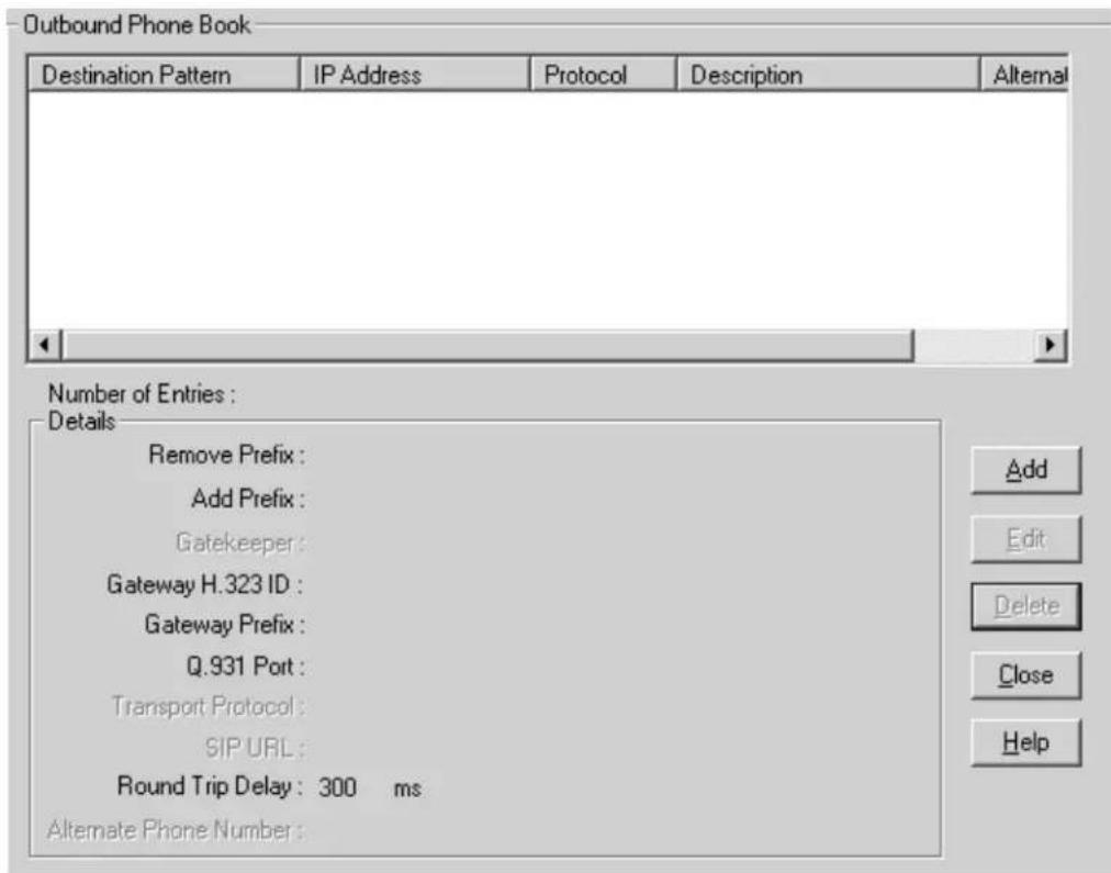
Outbound Phone Book Destination Pattern IP Address Protocol Description Alternal Number of Entries : Details Remove Prefix : Add Prefix : Gatekeeper : Gateway H.323 ID : Gateway Prefix : Q.931 Port : Transport Protocol : SIP URL : Round Trip Delay : 300 ms Alternate Phone Number : Add Edit Delete Close Help

  1. Click the Add button to add a phone book entry. In the Destination Pattern field, enter the identifying number for one of the remote MultiVOIP units. Enter the IP address of the remote MultiVOIP unit in the IP Address field. Leave the other fields set at their defaults.

Add/Edit Outbound Phone Book Phone Number Details Use as default entry Destination Pattern: 2 Total Digits: 0 Remove Prefix: Add Prefix: IP Address: 192 . 168 . 25 . 21 Description: Protocol Type SIP H.323 SPP H.323 Use GateKeeper Gateway H.323 ID : Gateway Prefix : Q.931 Port Number: 1720

  1. Click Ok when finished with this entry. Click the Add button as needed to create entries for other remote MultiVOIP units. In our example, the Corporate MultiVOIP would have two entries like below:

Outbound Phone Book Destination Pattern IP Address Protocol Description Alternate 2 192.168.025.021 H.323 3 192.168.025.022 H.323 Number of Entries: 2 Details Remove Prefix : Add Prefix : Gatekeeper: not used Gateway H.323 ID : Gateway Prefix : Q.931 Port: 1720 Transport Protocol : SIP URL : Round Trip Delay: 300 ms Alternate Phone Number:

The Branch A and Branch B MultiVOIP entries would look like this:

Outbound Phone Book Destination Pattern IP Address Protocol Description Alternate 1 192.168.025.020 H.323 Number of Entries: 1 Details Remove Prefix : Add Prefix : Gatekeeper: not used Gateway H.323 ID : Gateway Prefix : Q.931 Port: 1720 Transport Protocol : SIP URL : Round Trip Delay: 300 ms Alternate Phone Number : Add Edit Delete Close Help

  1. In the configuration / Voice/Fax screen, select one of the channels to be used for paging and click the Auto Call Enable checkbox to enable the auto call feature. In the Phone Number field, enter x:y where x equals the remote MultiVOIP identifying number and y equals the remote MultiVOIP Voice Channel number. For example, on Corporate MultiVOIP channel 1 you would enter 2:1 to communicate with Branch A voice channel 1. For best voice quality, configure the Voice Coder field to G.711 U-Law @ 64 kbps. For good voice quality requiring less bandwidth, configure the Voice Coder field to G.723.1 @ 6.3 kbps. You must use the same voice coder on channels that communicate with each other. Leave the other fields set to defaults. Configure the other channels as needed and click Ok when finished.

Voice/Fax Parameters Select Channel Channel 1 Voice Gain Input 0 dB Output 0 dB Dtmf Gain High -4 dB Low -7 dB Duration 100 ms DTMF: Out Of Band - Fixed Duration Fax Fax Enable Max Baud Rate 14400 Fax Volume -9.5 dB Jitter Value 400 ms Mode FRF 11 OK Cancel Copy Channel Default Help Coder Manual Automatic Selected Coder G.711 U - law @ 64 kbp- Max bandwidth 10 kbps Advanced Features Silence Compression Echo Cancellation Forward Error Correction Auto Call Auto Call Enable Generate Local Dial Tone Phone Number 2:1 Dynamic Jitter Buffer Minimum Jitter Value 60 ms Maximum Jitter Value 300 ms Optimization Factor 7 Automatic Disconnection Jitter Value 350 ms Consecutive Packets Lost 30 Call Duration 180 secs Network Disconnection 300 secs

Corporate Channel 1

Voice/Fax Parameters Select Channel Channel 2 Voice Gain Input 0 dB Output 0 dB Dtmf Gain High -4 dB Low -7 dB Duration 100 ms DTMF: Out Of Band - Fixed Duration Fax Fax Enable Max Baud Rate 14400 Fax Volume -9.5 dB Jitter Value 400 ms Mode FRF 11 OK Cancel Copy Channel Default Help Coder Manual Automatic Selected Coger G.711 U - law @ 64 kbp Max bandwidth 10 kbps Advanced Features Silence Compression Echo Cancellation Forward Error Correction Auto Call Auto Call Enable Generate Local Dial Tone Phgne Number 3:1 Dynamic Jitter Buffer Minimum Jitter Value 60 ms Maximum Jitter Value 300 ms Optimization Factor 7 Automatic Disconnection Jitter Value 350 ms Consecutive Packets Lost 30 Call Duration 180 secs Network Disconnection 300 secs

Corporate Channel 2

Voice/Fax Parameters Select Channel Channel 1 Voice Gain Input 0 dB Output 0 dB Dtml Gain High -4 dB Low -7 dB Duration 100 ms DTMF: Out Of Band - Fixed Duration Fax Fax Enable Max Baud Rate 14400 Fax Volume -9.5 dB Jitter Value 400 ms Mode FRF 11 Advanced Features Silence Compression Echo Cancellation Forward Error Correction Coder Manual Automatic Selected Coger G.711 U - law @ 64 kbp Max bandwidth 10 kbps Auto Call Auto Call Enable Generate Local Dial Tone Phone Number 1:1 Dynamic Jitter Buffer Minimum Jitter Value 60 ms Maximum Jitter Value 300 ms Optimization Factor 7 Automatic Disconnection Jitter Value 350 ms Consecutive Packets Lost 30 Call Duration 180 secs Network Disconnection 300 secs

Branch A Channel 1

Voice/Fax Parameters Select Channel Channel 1 Voice Gain Input 0 dB Output 0 dB Dtml Gain High -4 dB Low -7 dB Duration 100 ms DTMF: Out Of Band - Fixed Duration Fax Fax Enable Max Baud Rate 14400 Fax Volume -9.5 dB Jitter Value 400 ms Mode FRF 11 Advanced Features Silence Compression Echo Cancellation Forward Error Correction Coder Manual Automatic Selected Coder G.711 U - law @ 64 kbp Max bandwidth 10 kbps Auto Call Auto Call Enable Generate Local Dial Tone Phone Number 1:2 Dynamic Jitter Buffer Minimum Jitter Value 60 ms Maximum Jitter Value 300 ms Optimization Factor 7 Automatic Disconnection Jitter Value 350 ms Consecutive Packets Lost 30 Call Duration 180 secs Network Disconnection 300 secs

Branch B Channel 1

  1. Select Save Setup / Save and Reboot to save the configuration to the MultiVOIP.
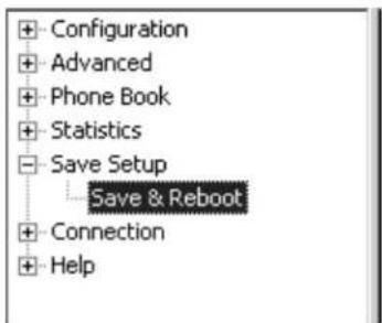
Configuration Advanced Phone Book Statistics Save Setup Save & Reboot Connection Help

  1. Assuming a Bogen PCMZPM is located at Corporate, connect a RJ11 phone cord to channel 1 FXS/FXO jack on the Corporate MultiVOIP. Connect the two wires on the other end of the phone cord to the Zone A + and - leads on the PCMZPM. Connect another RJ11 phone cord between channel 2 FXS/FXO jack and the Zone B + and - leads on the PCMZPM. A cord with an RJ11 plug on one end and tinned leads on the other end is included for this purpose. Caution: set the PCMZPM output selector switch to Low Power
  2. At the Branch sites, connect a RJ11 phone cord between the MultiVOIP channel 1 FXS/FXO jack and the TIP/RING leads of the speaker amplifier (TPU-15, for example). You cannot connect the speaker directly to the MultiVOIP.
  3. When all MultiVOIPs are powered on, a permanent audio connection will exist between Corporate MultiVOIP channel 1 and Branch A MultiVOIP channel 1. Another permanent audio connection will exist between Corporate MultiVOIP channel 2 and Branch B MultiVOIP channel 1. You can now make pages From Corporate to Branch A and/or Branch B remote sites.
Table of contents Click a title to access it
Manual assistant
Powered by Anthropic
Waiting for your message
Product information

Brand : Bogen

Model : MVP130BG

Category : Telephone