SHARK ZONE GS10 - Office chair Sharkoon - Free user manual and instructions
Find the device manual for free SHARK ZONE GS10 Sharkoon in PDF.


| Product Type | Office Chair |
| Model | SHARK ZONE GS10 |
| Brand | Sharkoon |
| Overall Height | 117 - 127 cm |
| Seat Height | 44 - 54 cm |
| Seat Width | 52 cm |
| Seat Depth | 48 cm |
| Backrest Height | 65 cm |
| Armrest Height | 58 - 73 cm |
| Weight Capacity | 120 kg |
| Net Weight | 13.5 kg |
| Base Material | Nylon |
| Seat Material | Mesh fabric |
| Backrest Material | Mesh fabric |
| Armrest Material | PU with 3D adjustment |
| Gas Lift Class | Class 3 |
| Adjustable Features | Seat height, tilt lock, armrest height, angle and width, lumbar support |
| Recommended Cleaning | Wipe with damp cloth, mild soap, avoid solvents |
| Safety Standards | EN 1335, BIFMA, TUV |
| Assembly Required | Yes, tools included |
| Warranty | 2 years |
Frequently Asked Questions - SHARK ZONE GS10 Sharkoon
User questions about SHARK ZONE GS10 Sharkoon
0 question about this device. Answer the ones you know or ask your own.
Ask a new question about this device
Download the instructions for your Office chair in PDF format for free! Find your manual SHARK ZONE GS10 - Sharkoon and take your electronic device back in hand. On this page are published all the documents necessary for the use of your device. SHARK ZONE GS10 by Sharkoon.
USER MANUAL SHARK ZONE GS10 Sharkoon
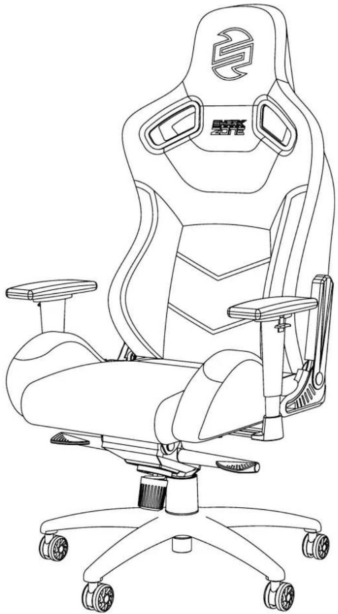
natural_image
Line drawing of a modern office chair with ergonomic seat, wheels, and camera (no text or symbols)EN Package Contents
A) 1x Backrest
B) 1x Seatbase with armrests
C) 1x Chair mechanism
D) 1x Five-star base
E) 5x Wheels
F) 1x Gas lift piston
G) 1x Piston cover
H) 2x Side covers
I) 1x Allen wrench (M8)
J) 8x M8 screws (pre-installed)
K) 1x Headrest cushion
L) 1x Lumbar cushion
3 Safety Instructions

EN Safety Instructions
A) We recommended that the chair be assembled with the help of a second person.
B) To avoid dropping the chair, ensure the weight is evenly distributed.
C) Ensure to keep your feet on the ground at all times and do not press your head against the backrest while fully reclining in the chair.
D) Do not place heavy objects on the chair and do not use it as a ladder.
E) When adjusting the backrest, ensure your fingers are out of the way.
F) To avoid damage, never pull hard and fast on the handles.
G) Avoid direct sunlight to ensure plastic components do not become brittle.
H) Do not use aggressive cleaning agents to clean the chair.
4 | Five-Star Base and Gas Lift Piston
EN Five-Star Base and Gas Lift Piston
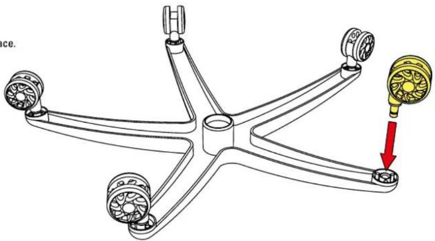
Insert the wheels into the five-star base until they click into place.
natural_image
Mechanical assembly diagram showing a five-petal star-shaped component with four wheels and a central hub, connected by a red arrow pointing to a yellow component (no text or symbols present)EN Five-Star Base and Gas Lift Piston
Insert the gas lift piston into the five-star base and then slide the piston cover over the gas lift.
To attach, pull the lumbar cushion straps through the backrest openings from front to back.
This can also be done after the chair is assembled.
DE Optionales Lendenkissen
To secure the cushion, connect both buckles from the bottom and top of the backrest.
DE Optionales Lendenkissen
6 Connect Seat Back with Seat Base
EN Connect Seat Back with Seat Base
Remove the four pre-installed M8 screws from the backrest using the M8 Allen wrench. Align the backrest and the rear of the seat base carefully according to the picture.
natural_image
Technical line drawing of a car seatbelt mechanism with red arrows indicating fasteners (no text or symbols present)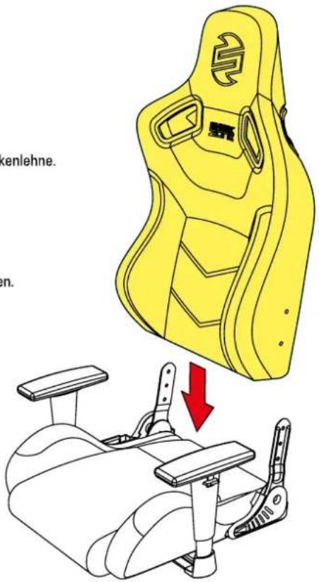
EN Connect Seat Back with Seat Base
Now use the M8 Allen wrench and the previously removed M8 screws to attach the backrest to the seat base.
natural_image
Mechanical assembly diagram showing a yellow bracket and lever mechanism (no text or symbols)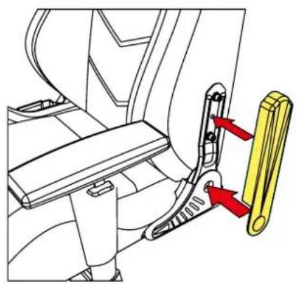
natural_image
Mechanical assembly diagram showing a belt buckle and yellow component with red arrows indicating motion (no text or symbols)EN Side Covers
Attach the side covers to the support brackets on the chair.
8 Mechanism Mounting
EN Mechanism Mounting
Remove the four pre-installed M8 screws with the M8 Allen wrench from the bottom of the seat base. Align the chair mechanism according to the posted directions on the bottom of the seat base. Attach the chair mechanism by using the previously removed M8 screws.
natural_image
Technical line drawing of a mechanical device with red arrows indicating motion or assembly (no text or symbols)9 | Linking the Parts
EN Linking the Parts
Lastly, connect the base and chair by inserting the gas lift piston into the opening on the chair mechanism. The chair is now successfully assembled.
10 | Optional Headrest Cushion
EN Optional Headrest Cushion
If desired, the provided headrest cushion can be used.
To do this, attach the cushion behind the backrest at the desired height.
11 Seat Backrest Adjustment
natural_image
Mechanical assembly diagram showing a yellow belt mechanism interacting with a blue bracket, with a red arrow indicating motion direction (no text or symbols present)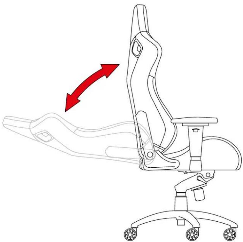
natural_image
Line drawing of an office chair with a red arrow indicating motion or change, no text or symbols presentEN Seat Backrest Adjustment
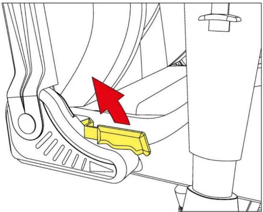
To adjust the backrest, first pull the handle on the right-side of the seat base.
Lean forwards or backwards to tilt the backrest into the desired position.
Once the backrest is in the desired position, release the handle to lock the backrest into place.
12 | Seat Height Adjustment
EN Seat Height Adjustment
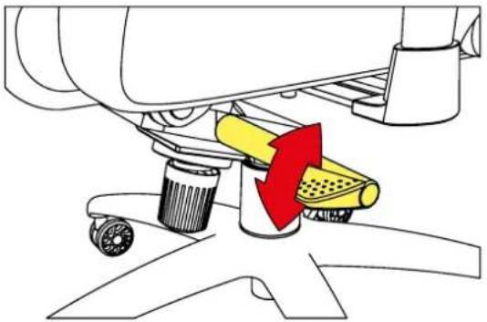
The seat height can be adjusted via the right handle underneath the seat base.
The chair will move into a lower position if simultaneous pressure is placed
on the seat base surface while the handle is pulled.
The chair will move into a higher position if no simultaneous pressure
is placed on the seat base surface while the handle is pulled.
Once the seat is at the desired height, release the handle to lock the seat into place.
natural_image
Diagram of a mechanical assembly with a yellow component and red arrow indicating motion (no text or symbols)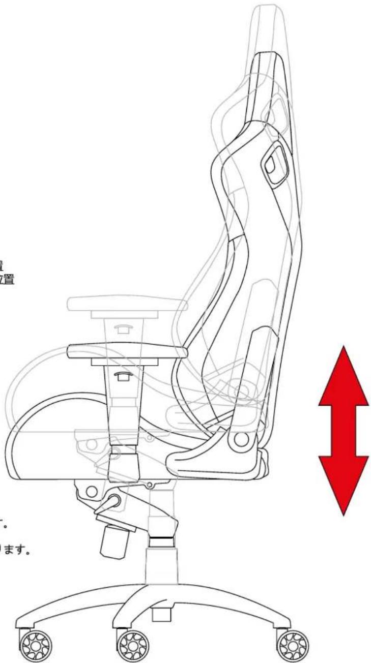
natural_image
Diagram of a mechanical assembly with a red arrow indicating force or movement, no text or symbols presentCN 傾斜機構調整
natural_image
Diagram of a mechanical device with a yellow component and red directional arrows indicating motion (no text or symbols)13 | Tilt Mechanism Adjustment
EN Tilt Mechanism Adjustment
The tilt mechanism can be adjusted via the left handle underneath the seat base. The tilt mechanism is unlocked when the handle is pulled upwards. The tilt mechanism is locked when the handle is pulled downwards. The backrest can be locked into several positions
EN Tilt Mechanism Adjustment
Tilt mechanism resistance can also be adjusted via means of the rotary knob located underneath the seat. While sitting on the chair, turn the knob right to decrease the resistance and left to increase resistance.
14 Adjustment of Armrests
EN Adjustment of Armrests
To adjust the armrest height, pull the handle upwards. While holding the handle, the armrest can be moved upwards and downwards to the desired position. Once the armrest is in the desired position, release the handle to lock the armrest into place.
natural_image
Technical diagram of a mechanical device with red directional arrows indicating movement or force (no text or symbols present)EN Adjustment of Armrests
The armrest can be moved back and forth without the use of a button.
natural_image
Diagram of a car's seat and dashboard mechanism with red arrows indicating motion (no text or symbols)natural_image
Diagram showing a mechanical component with a red arrow indicating downward motion, no text or symbols presentEN Adjustment of Armrests
The armrest can be tilted inwards and outwards without the use of a button.
natural_image
Line drawing of a modern office chair with ergonomic seat, wheels, and camera (no text or symbols)- EN Package Contents
- Safety Instructions
- EN Safety Instructions
- | Five-Star Base and Gas Lift Piston
- EN Five-Star Base and Gas Lift Piston
- DE Optionales Lendenkissen
- Connect Seat Back with Seat Base
- EN Connect Seat Back with Seat Base
- EN Side Covers
- Mechanism Mounting
- EN Mechanism Mounting
- | Linking the Parts
- EN Linking the Parts
- | Optional Headrest Cushion
- EN Optional Headrest Cushion
- Seat Backrest Adjustment
- EN Seat Backrest Adjustment
- | Seat Height Adjustment
- EN Seat Height Adjustment
- CN 傾斜機構調整
- | Tilt Mechanism Adjustment
- EN Tilt Mechanism Adjustment
- Adjustment of Armrests
- EN Adjustment of Armrests
Brand : Sharkoon
Model : SHARK ZONE GS10
Category : Office chair