ADE-3400A - Router Planet - Free user manual and instructions
Find the device manual for free ADE-3400A Planet in PDF.


| Product Type | ADSL2+ Router |
| Dimensions (W x D x H) | 180 x 120 x 30 mm |
| Weight | 300 g |
| Power Supply | 12 V DC, 1 A |
| Wireless Standard | IEEE 802.11b/g/n |
| Frequency Band | 2.4 GHz |
| Data Transfer Rate | Up to 300 Mbps |
| WAN Interface | RJ11 (ADSL) |
| LAN Interface | 4 x RJ45 10/100 Mbps |
| Security | WPA2, WPA, WEP, Firewall, SPI, DoS Prevention |
| VPN Support | PPTP, L2TP, IPSec Pass-through |
| QoS | Bandwidth Control |
| LED Indicators | Power, ADSL, Internet, WiFi, LAN1-4 |
| Antenna Type | 2 x Fixed Omni-directional |
| Care and Cleaning | Wipe with dry cloth; avoid liquids and direct sunlight |
| Safety | Keep away from water and heat sources; use only provided adapter |
| Spare Parts and Repairability | Power adapter and network cables available separately; user replaceable |
| General Information | Brand: Planet; Model: ADE-3400A; Designed for home and small office |
Frequently Asked Questions - ADE-3400A Planet
User questions about ADE-3400A Planet
0 question about this device. Answer the ones you know or ask your own.
Ask a new question about this device
Download the instructions for your Router in PDF format for free! Find your manual ADE-3400A - Planet and take your electronic device back in hand. On this page are published all the documents necessary for the use of your device. ADE-3400A by Planet.
USER MANUAL ADE-3400A Planet
Copyright © 2013 by PLANET Technology Corp. All rights reserved. No part of this publication may be reproduced, transmitted, transcribed, stored in a retrieval system, or translated into any language or computer language, in any form or by any means, electronic, mechanical, magnetic, optical, chemical, manual or otherwise, without the prior written permission of PLANET.
PLANET makes no representations or warranties, either expressed or implied, with respect to the contents hereof and specifically disclaims any warranties, merchantability or fitness for any particular purpose. Any software described in this manual is sold or licensed "as is". Should the programs prove defective following their purchase, the buyer (and not PLANET, its distributor, or its dealer) assumes the entire cost of all necessary servicing, repair, and any incidental or consequential damages resulting from any defect in the software. Further, PLANET reserves the right to revise this publication and to make changes from time to time in the contents hereof without obligation to notify any person of such revision or changes.
All brand and product names mentioned in this manual are trademarks and/or registered trademarks of their respective holders.
Federal Communication Commission Interference Statement
This equipment has been tested and found to comply with the limits for a Class B digital device, pursuant to Part 15 of FCC Rules. These limits are designed to provide reasonable protection against harmful interference in a residential installation. This equipment generates, uses, and can radiate radio frequency energy and, if not installed and used in accordance with the instructions, may cause harmful interference to radio communications. However, there is no guarantee that interference will not occur in a particular installation. If this equipment does cause harmful interference to radio or television reception, which can be determined by turning the equipment off and on, the user is encouraged to try to correct the interference by one or more of the following measures:
- Reorient or relocate the receiving antenna.
- Increase the separation between the equipment and receiver.
- Connect the equipment into an outlet on a circuit different from that to which the receiver is connected.
- Consult the dealer or an experienced radio technician for help.
FCC Caution
To assure continued compliance, use only shielded interface cables when connecting to computer or peripheral devices. Any changes or modifications not expressly approved by the party responsible for compliance could void the user's authority to operate the equipment.
This device complies with Part 15 of the FCC Rules. Operation is subject to the following two conditions: (1) This device may not cause harmful interference, and (2) this Device must accept any interference received, including interference that may cause undesired operation.
Federal Communication Commission (FCC) Radiation Exposure Statement
This equipment complies with FCC radiation exposure set forth for an uncontrolled environment. In order to avoid the possibility of exceeding the FCC radio frequency exposure limits, human proximity to the antenna shall not be less than 20 cm (8 inches) during normal operation.
Safety
This equipment is designed with the utmost care for the safety of those who install and use it. However, special attention must be paid to the dangers of electric shock and static electricity when working with electrical equipment. All guidelines of this and of the computer manufacture must therefore be allowed at all times to ensure the safe use of the equipment.
CE Mark Warning
This is a Class B product. In a domestic environment, this product may cause radio interference, in which case the user may be required to take adequate measures.
WEEE Regulation

To avoid the potential effects on the environment and human health as a result of the presence of hazardous substances in electrical and electronic equipment, end users of electrical and electronic equipment should understand the meaning of the crossed-out wheeled bin symbol. Do not dispose of WEEE as unsorted municipal waste and have to collect such WEEE separately.
Revision
User's Manual for ADSL 2/2+ Router
Model: ADE-3400
Rev: 6.0 (October. 2013)
Part No. EM-ADE3400_v6
Contents
Chapter 1. Overview ......3
1.1 Application 3
1.2 System Requirements 6
1.3 Features 7
1.4 Specifications 9
Chapter 2. Hardware Installation 11
Chapter 3. Web Configuration ……12
3.1 Accessing the Router 12
3.2 Status 13
3.2.1 Device Information 13
3.2.2 ADSL 13
3.2.3 Statistics 14
3.3 Wizard 15
3.4 Setup 21
Improved Networking Function for Future IP Compatibility
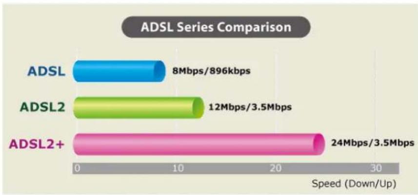
PLANET ADE-3400 is an ADSL 2/2+ Router. The ADE-3400 is the ideal solution for office and residential users to share a high-speed ADSL 2/2+ broadband Internet connection and four-10/100Mbps Fast Ethernet backbone. It can support transmission rates up to 24Mbps downstream and 3.5Mbps upstream with ADSL 2+ support. Through integration with single chipset to reduce boot time, the ADE-3400 offers more performance to users. The ADE-3400 supports PPPoA (RFC 2364 - PPP over ATM Adaptation Layer 5), RFC 2684 encapsulation over ATM (bridged or routed), PPP over Ethernet (RFC 2516), and IPoA (RFC1483) to establish a connection with ISP.
bar
ADSL Series Comparison | Series | Speed (Mbps) | Speed (Kbps) | | :--- | :--- | :--- | | ADSL | 8 | 896 | | ADSL2 | 12 | 3.5 | | ADSL2+ | 24 | 3.5 |Powerful Firewall and Complete Access Control Functions
The ADE-3400 has user-friendly management interfaces so it can be managed by workstations running standard web browsers. It provides DHCP server, NAT, Virtual Server, DMZ, Access Control, IP Filter, DDNS, and UPnP capability. The ADE-3400 also serves as an Internet firewall to protect your network from being accessed by unauthorized users. It offers the natural firewall function. All the incoming and outgoing IPs can be monitored and filtered. For the advanced application, it even can block internal users accessing to the Internet services.
1.1 Application
Wired Internet Connection
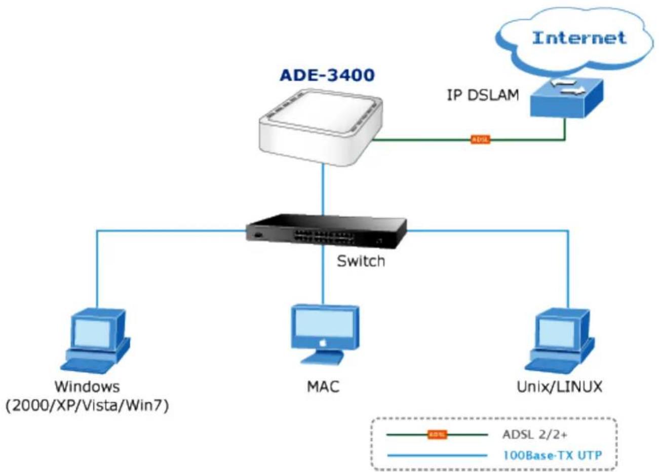
The ADE-3400 is a perfect solution for a small group of PCs connecting to a high-speed broadband Internet connection. Multi-users can access to the Internet simultaneously.
flowchart
graph TD
    A["Windows (2000/XP/Vista/Win7)"] --> B["Switch"]
    C["MAC"] --> B
    D["Unix/LINUX"] --> B
    E["Internet"] --> F["IP DSLAM"]
    G["ADSL 2/2+"] --> H["Switch"]
    I["100Base-TX UTP"] --> H
    H --> B
    style H fill:#f9f,stroke:#333
Front Panel
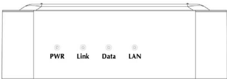
The following table describes the LEDs of the device.
| LED | State | Description |
| PWR | ON When the router is powered on and in ready state. | |
| Red The devise is being turned on and booting. | ||
| OFF When the router is powered off. | ||
| Link | ON | Successful connection between ADSL modem and telecom's network. |
| Flashing Modem is trying to establish a connection to telecom's network. | ||
| Data Flashing Data is transferred when Router connected network or Internet. | ||
| LAN | ON | Link |
| Flashing TX or RX activity. | ||
Rear Panel
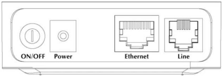
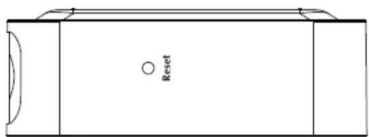
The following table describes the interfaces and buttons of the device.
| Connector Description | |
| POWER Button | The power button is for turn on or turns off the router. |
| Power Power con | nector with 5V DC, 1A |
| Reset | The reset button can restore the default settings of device. To restore factory defaults, keep the device powered on and push a paper clip into the hole. Press down the button over 5 seconds and then release. |
| Ethernet | Router is successfully connected to a device through the Ethernet port. If the LED is flashing, the Router is actively sending or receiving data over that port. |
| Line | The RJ-11 connector allows data communication between the modem and the ADSL network through a twisted-pair phone wire. |
1.2 System Requirements
Make sure first that you have prepared these following items to guarantee the router can work normally.
● Services subscriptions.
● An 10/100Mbps Ethernet card installed on your PC.
- Hub or Switch. (Attached to several PCs through one of Ethernet interfaces on the device).
● Operating system: Windows 7, Windows 2000, or Windows XP.
- Internet Explorer V8.0 or higher, or firefox v23 or higher.
1.3 Features
The device supports the following features:
Internet Access Features
- Internet Access Shared
All users in the LAN can access the Internet through the ADE-3400 by just a single external IP Address. The local (invalid) IP Addresses are hidden from external sources. This process is called NAT (Network Address Translation).
Built-in ADSL 2/2+ Modem
The ADE-3400 provides ADSL 2/2+ modem service and supports all common ADSL connections.
- PPPoE, PPPoA, Direct Connection Support
Various WAN connections are supported by the ADE-3400.
♦ Fixed or Dynamic IP Address
On the Internet (WAN port) connection, the ADE-3400 supports both Dynamic IP Address (IP Address is allocated on connection) and Fixed IP Address.
Advanced Internet Functions
- Virtual Servers
This feature allows Internet users to access Internet servers on your LAN. The required setup is quick and easy.
- DMZ Support
The ADE-3400 can translate public IP addresses into private IP address and allow unrestricted 2-way communication with servers or individual users on the Internet. This provides the most flexibility to run programs which could be incompatible in NAT environment.
- Firewall
The ADE-3400 supports simple firewall with NAT technology and provides options for access control from Internet like Telnet, FTP, TFTP, HTTP, SNMP, and ICMP services. It also supports IP/ MAC/ Application/ URL filtering.
♦ Universal Plug and Play (UPnP)
UPnP allows automatically discovering and configuration of the Broadband Router. UPnP is supported by Windows XP, Windowa 7 or later.
- Dynamic DNS Support
The ADE-3400 supports Planet Dynamic DNS that it's free for customer.
- Based on the Virtual Servers feature, the ADE-3400 allows users to connect a server to the LAN by using a Domain Name even if you have a dynamic IP address.
- RIP Routing
It supports RIPv1/2 routing protocol for routing capability.
- Simple Network Management Protocol (SNMP)
It is an easy way to remotely manage the router via SNMP.
LAN Features
- DHCP Server Support
Dynamic Host Configuration Protocol provides a dynamic IP address to PCs and other devices upon request. The ADE-3400 can act as a DHCP Server for devices on your local LAN and WLAN.
1.4 Specifications
| Product | ADSL 2/2+ Router | |
| Model ADE-3400A | ||
| Hardware | ||
| Standard | Compliant with ADSL Standard- Full-rate ANSI T1.413 Issue 2- G.dmt (ITU G.992.1)- G.lite (ITU G.992.2)- G.hs (ITU G.994.1)Capable of ADSL2 Standard- G.dmt.bis (ITU G.992.3) Annex A, L and M- G.lite.bis (ITU G.992.4)Capable of ADSL2+ Standard- G.dmt.bisplus (ITU G.992.5) | |
| Protocol | RFC 1483 BridgeRFC 1483 RouterIEEE 802.1D transparent bridgingBridge FilteringBridged or routed Ethernet encapsulationVC and LLC based multiplexingPPP over Ethernet (PPPoE)PPP over ATM (RFC 2364) | |
| AAL and ATM Support | Support up to 8PVCsVC and LLC MultiplexingATM Adaptation Layer Type 5 (AAL5)Integrated ATM AAL5 support(UBR,CBR,VBR,VBR-rt, and VBR-nrt)OAM F4/F5 | |
| Ports | LAN 1 x 10Base-T | 100Base-TX, Auto-Negotiation, Auto MDI/MDI-X |
| WAN | 1 x RJ-11, Auto-Negotiation | |
| LED Indicators PWR, Link | Data, LAN | |
| Max. Concurrent Sessions | 4096 | |
| Software | ||
| Protocol / Feature | NAT supports PAT/NAPT and multimedia applicationsStatic routing and RIPv1/2Transparent BridgingSNTPDNS relayIGMP ProxyIGMP MulticastDMZ and Virtual Server | |
| Security | Built-in NAT FirewallIP Port Filter, MAC Filter, URL Blocking, DoS SettingPPP over PAP (Password Authentication Protocol;RFC1334)PPP over CHAP (Challenge Authentication Protocol;RFC1994)Access Control List (ACL)Denial of Service (DoS)IP-based Packet filteringMAC filteringURL filteringPassword protection for system management | |
| VPN | VPN Pass-Through | |
| Management | Web-based configurationEmbedded Telnet server for remote and local managementConfiguration data upload and download via WEBFirmware upgraded via WEB and TFTPQoSSNMP v2 MIB supportedSupport DHCP server/relayBuilt-in Diagnostic tool and IP PingTR-069 | |
| Environment Specification | ||
| Dimension (W x D x H) 78 x 7 | 4 x 26 mm | |
| Power 5V DC, 1A (Consumption 2.1W) | ||
| Temperature:Humidity | Operating temperature: 0 ~ 50 Degree CStorage temperature: -40 ~ 70 Degree CHumidity: 5 ~ 95% non-condensing | |
| Emission | FCC, CE | |
Chapter 2. Hardware Installation
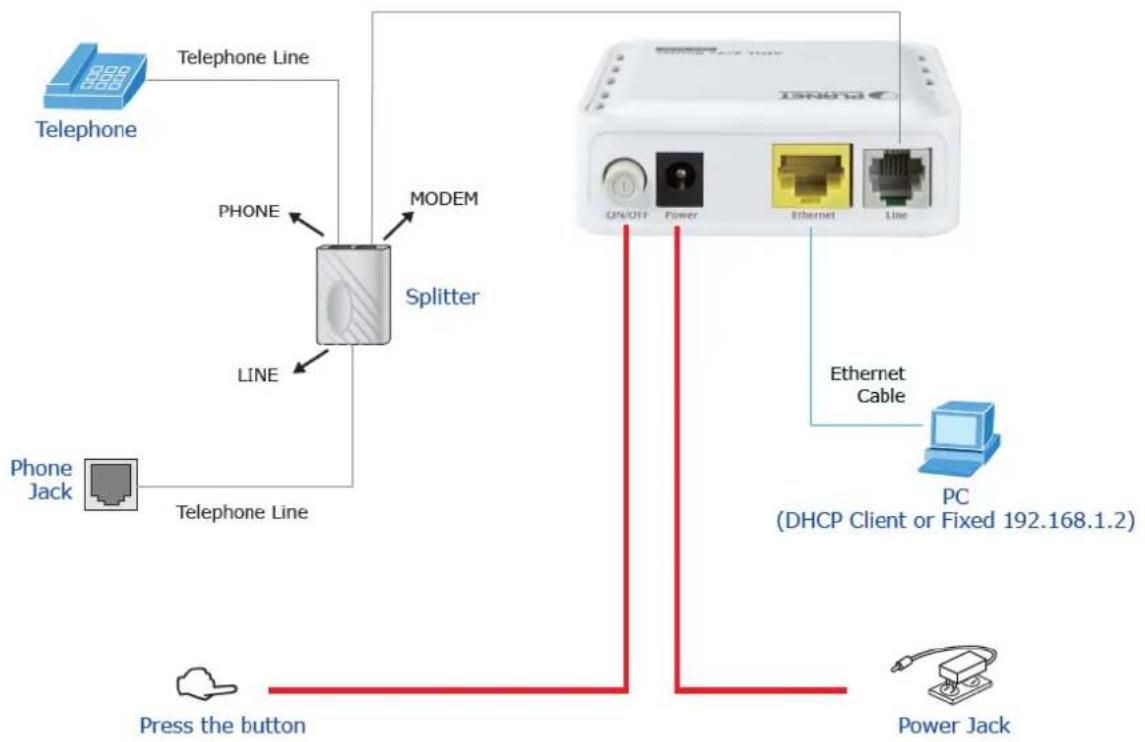
Connect the LINE interface of the device and the Modem interface of the splitter with a telephone cable. Connect the phone set to the Phone interface of the splitter through a telephone cable. Connect the input cable to the Line interface of the splitter.
The splitter has three interfaces:
● Line: Connect to a wall phone interface (RJ-11 jack).
● Modem: Connect to the LINE interface of the device.
● Phone: Connect to a telephone set.
Connect the LAN interface of the device to the network card of the PC through an Ethernet cable (MDI/MDIX).

Use the twisted-pair cable to connect the hub or switch.
Insert one end of the power adapter to the wall outlet and connect the other end to the POWER interface of the device.
The following figure shows the application diagram for the connection of the router, PC, splitter and the telephone sets.
flowchart
graph TD
    A["Telephone"] -->|Telephone Line| B["Splitter"]
    C["Phone Jack"] -->|Telephone Line| B
    D["Power Jack"] -->|Press the button| B
    E["Ethernet Cable"] --> F["PC (DHCP Client or Fixed 192.168.1.2)"]
    G["ON/OFF"] --> H["Switch"]
    I["Power"] --> H
    J["Ethernet"] --> H
    K["Line"] --> B
    L["MODEM"] --> B
    M["PHONE"] --> B
Chapter 3. Web Configuration
This chapter describes how to configure the device by using the Web-based configuration utility.
3.1 Accessing the Router
The following describes how to access the device for the first time in details.
Step 1 Open the Internet Explorer (IE) browser and enter http://192.168.1.1 in the address bar.
Step 2 In the Login page that is displayed, enter the username and password, and then click OK.
● The username and password of the super user are admin and admin.
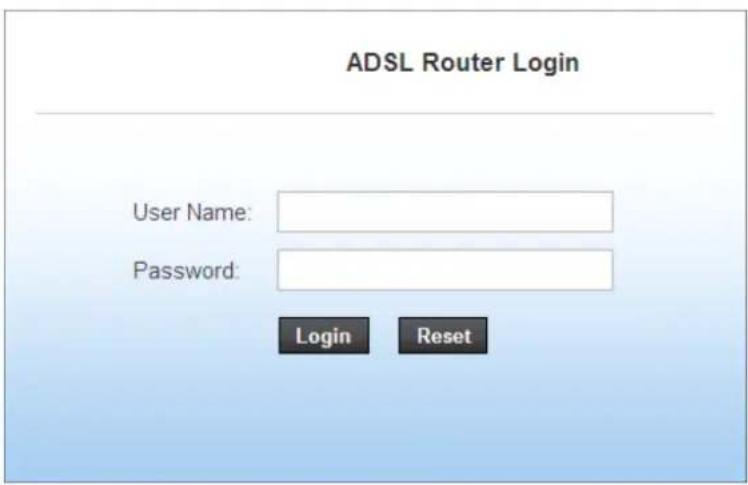
After logging in, the page shown in the following figure appears. You can check, configure and modify all the settings.

On the Web configuration page, you can click Apply Changes to save the settings temporarily. If you want to save the settings of this page permanently, clicks save of Attention that appears at the bottom of the Web page after the configuration.
3.2 Status
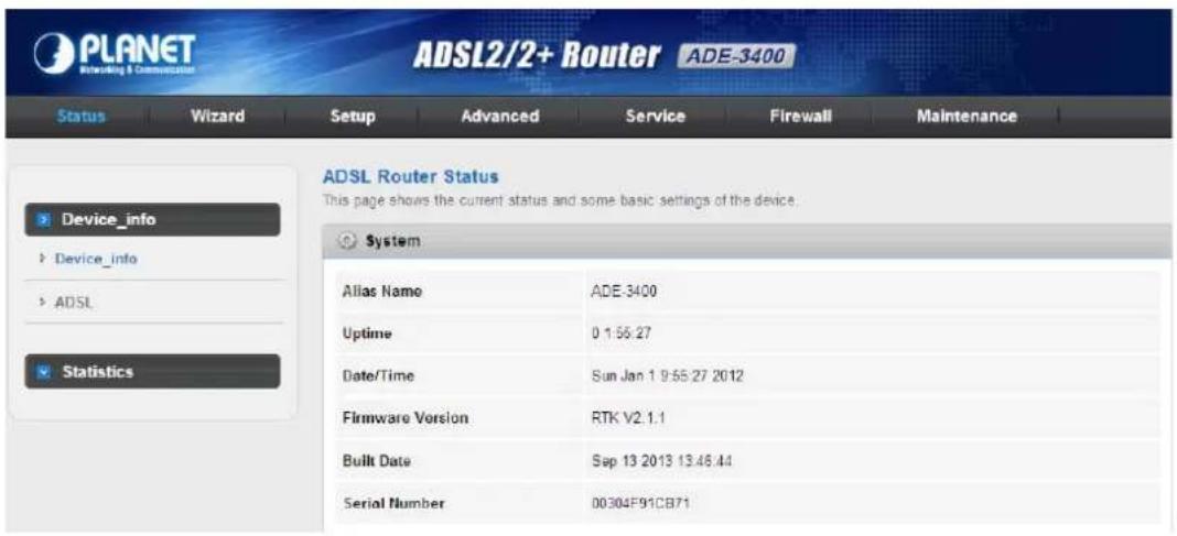
In the navigation bar, choose Status. On the Status page that is displayed contains: Device Info, ADSL and Statistics.
3.2.1 Device Information
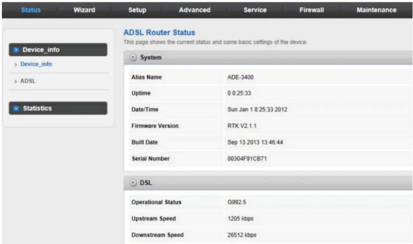
Choose Status > Device Info and the page displayed shows the current status and some basic settings of the router, such as software version, DSP version, uptime, upstream speed, and downstream speed.
3.2.2 ADSL
Click ADSL in the left pane and the page shown in the following figure appears. On this page, you can view the ADSL line status, upstream rate, downstream rate and other information.
Choose Status > LAN and the page displayed shows some basic LAN settings of the router. On this page, you can view the LAN IP address, DHCP server status, MAC address, and DHCP client table.
| Status | Wizard | Setup | Advanced | Service | Firewall | Maintenance |
| ADSL Configuration This page shows the setting of the ADSL Router. | ||||||
| Adsl Line Status | SHOWTIME.L0 | |||||
| Adsl Mode | G992.5 | |||||
| Up Stream | 1205 kbps | |||||
| Down Stream | 26512 kbps | |||||
| Attenuation Down Stream | 0 | |||||
| Attenuation Up Stream | 0 | |||||
| SNR Margin Down Stream | 6.6 | |||||
| SNR Margin Up Stream | 6.0 | |||||
| Vendor ID | RETK | |||||
| Firmware Version | 4925ca26 | |||||
| CRC Errors | 0 | |||||
| Up Stream BER | 0e-7 | |||||
| Down Stream BER | 0e-7 | |||||
3.2.3 Statistics
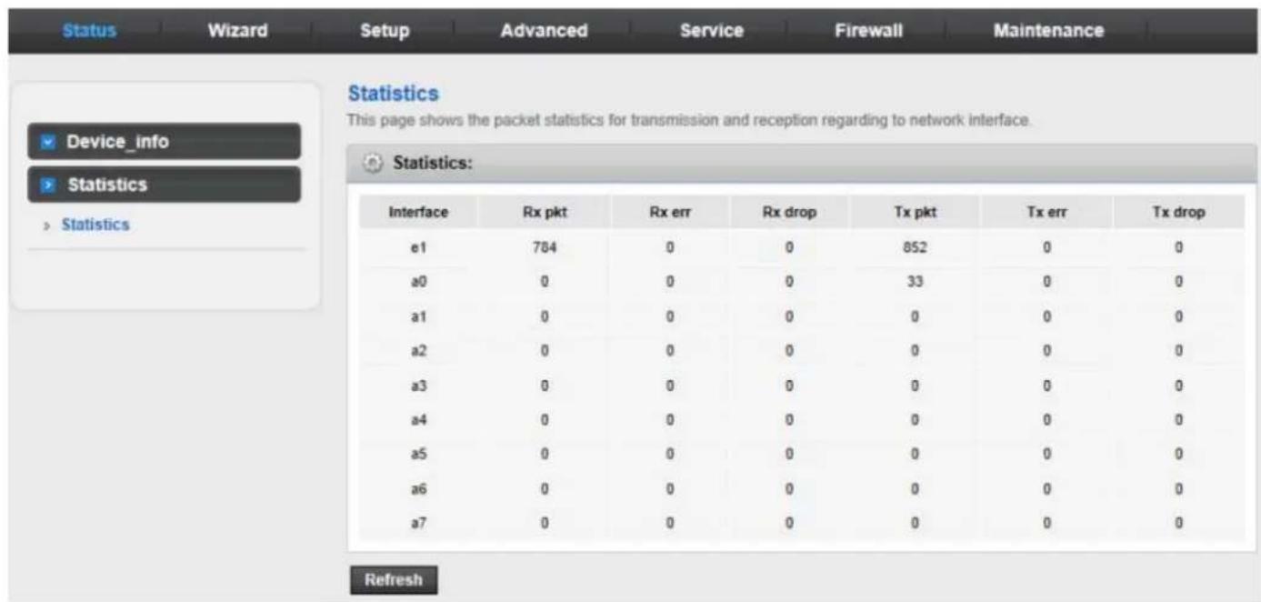
Choose Status > Statistics. Click Statistics in the left pane and the page shown in the following figure appears. On this page, you can view the statistics of each network port.
3.3 Wizard
When subscribing to a broadband service, you should be aware of the method by which you are connected to the Internet. Your physical WAN device can be either PPP, ADSL, or both. The technical information about the properties of your Internet connection is provided by your Internet Service Provider (ISP). For example, your ISP should inform you whether you are connected to the Internet using a static or dynamic IP address, and the protocol that you use to communicate on the Internet.
In the navigation bar, choose Wizard. The page shown in the following figure appears. The Wizard page guides fast and accurate configuration of the Internet connection and other important parameters. The following sections describe these various configuration parameters. Whether you configure these parameters or use the default ones, click NEXT to enable your Internet connection.
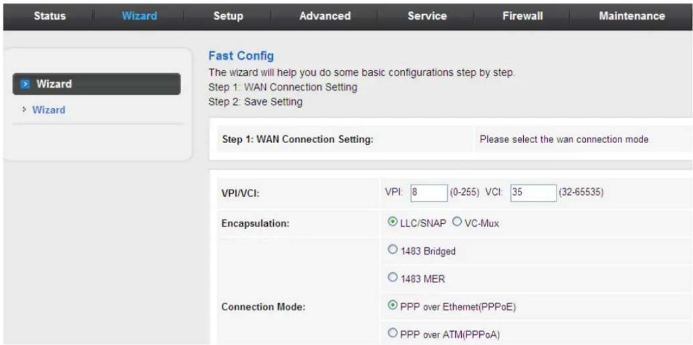
The following table describes the parameters on this page:
| Field Description | |
| VPI | Virtual path identifier (VPI) is the virtual path between two points in an ATM network. Its valid value is in the range of 0 to 255. Enter the correct VPI provided by your ISP. By default, VPI is set to 0. |
| VCI | Virtual channel identifier (VCI) is the virtual channel between two points in an ATM network. Its valid value is in the range of 32 to 65535. (0 to 31 is reserved for local management of ATM traffic) Enter the correct VCI provided by your ISP. By default, VCI is set to 0. |
There are five WAN connection types: 1483 Bridged, 1483 MER, PPP over Ethernet (PPPoE), PPP over ATM (PPPoA), 1483 Routed, and. The following describes them respectively.
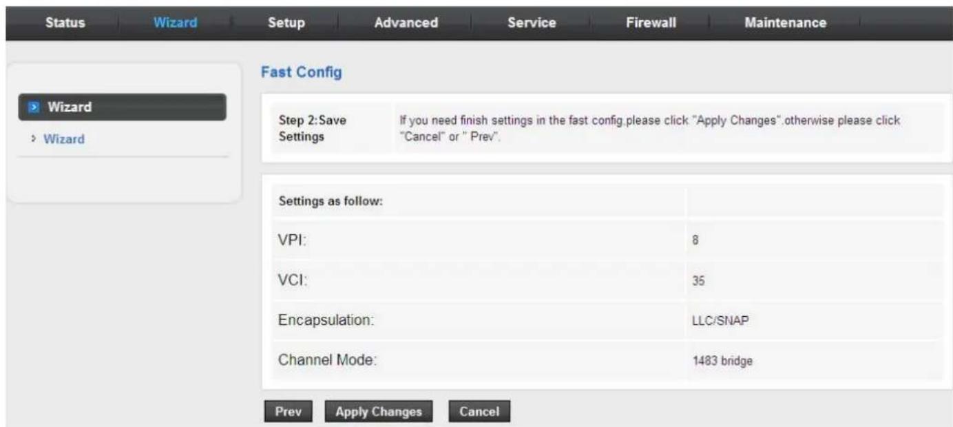
Bridge
After setting, click Next and the page as shown in the following figure appears.
PPPoE/PPPoA
On the Connection Type page set the WAN connection type to PPP over Ethernet (PPPoE), and the encapsulation mode to LLC/SNAP.
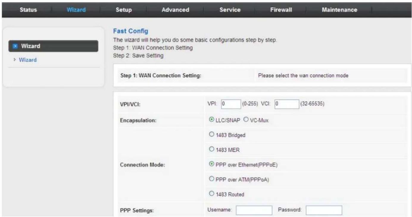
| Field Description | |
| PPP Username Enter the | username for PPPoE dial-up, which is provided by your ISP. |
| PPP Password Enter the | password for PPPoE dial-up, which is provided by your ISP. |
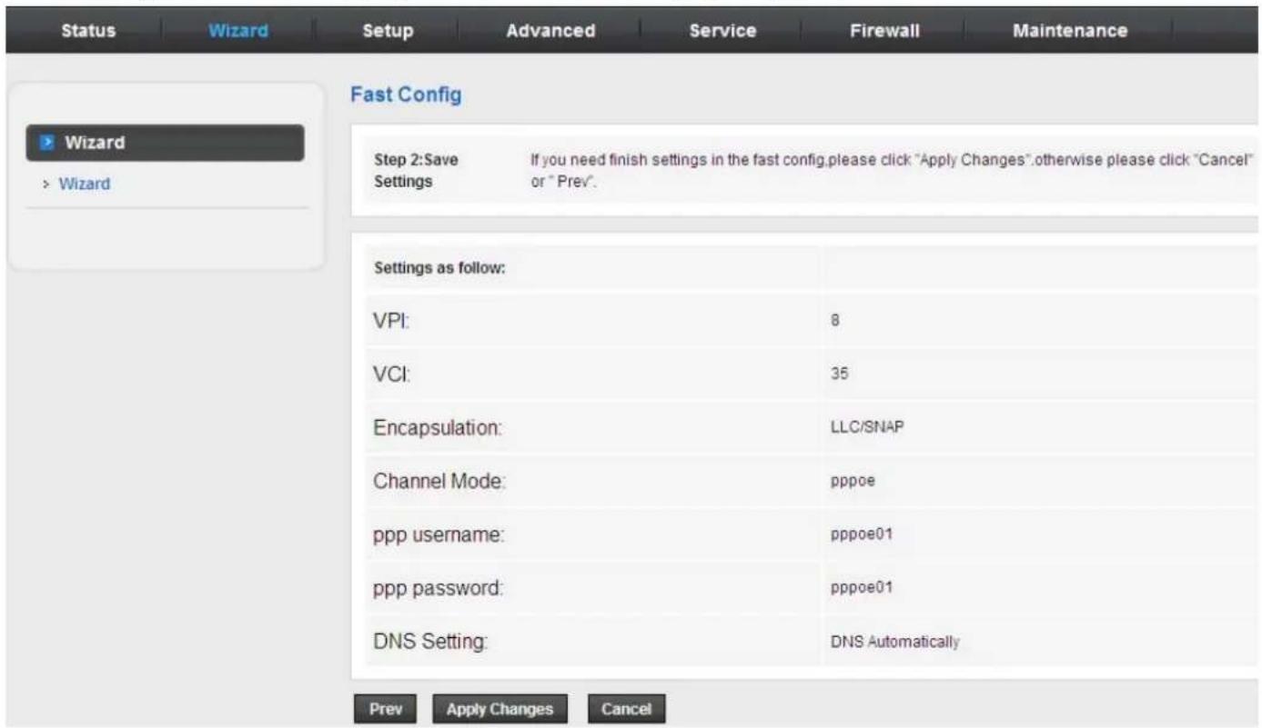
After setting, click Next and the page as shown in the following figure appears.

Note
If the WAN connection type is set to PPPoA, the parameters of the WAN connection type are the same as that of PPPoE. For the parameters on these pages, refer to the parameter description of PPPoE.
1483 MER/1483 Routed
On the Connection Type page set the WAN connection type to 1483 MER, and the encapsulation mode to LLC/SNAP.
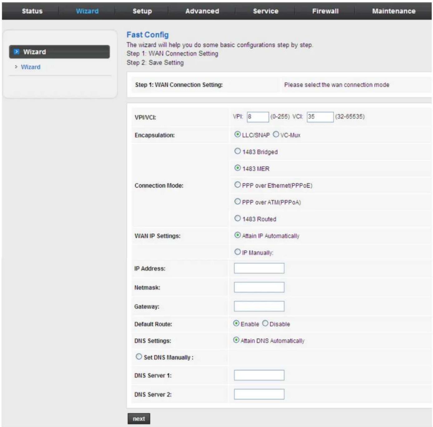
After setting, click Next and the page as shown in the following figure appears.
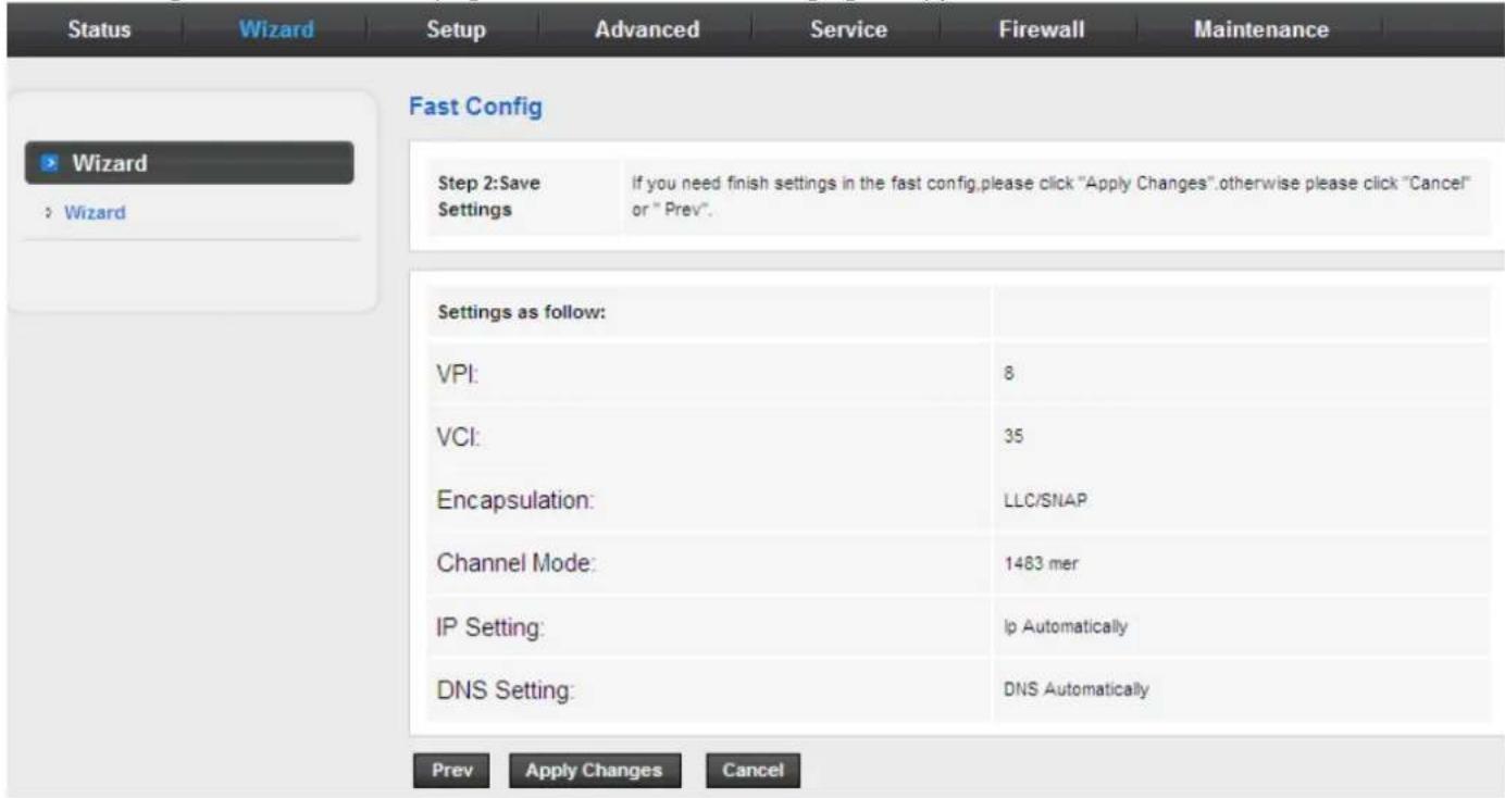
The following table describes the parameters on this page:
| Field Description | |
| Attain IP Automatically | Select it, DHCP automatically assigns the IP address for WAN connection. |
| IP Manually | When selecting it, you need to manually enter the IP address, subnet mask, and default gateway for WAN connection, which are provided by your ISP. |
| Attain DNS Automatically Select it, DHCP automatically assigns DNS server address. | |
| Set DNS Manually | Select it, you need to manually enter the primary DNS server address and secondary DNS server address. |
For subsequent configuration, refer to the description in the above section PPPoE/PPPoA.

If the WAN connection type is set to 1483 Routed, the parameters of the WAN connection type are the same as that of 1483 MER. For the parameters on these pages, refer to the parameter description of 1483 MER.
1483 Bridged
On the Connection Type page set the WAN connection type to 1483 Bridged, and the encapsulation mode to LLC/SNAP.
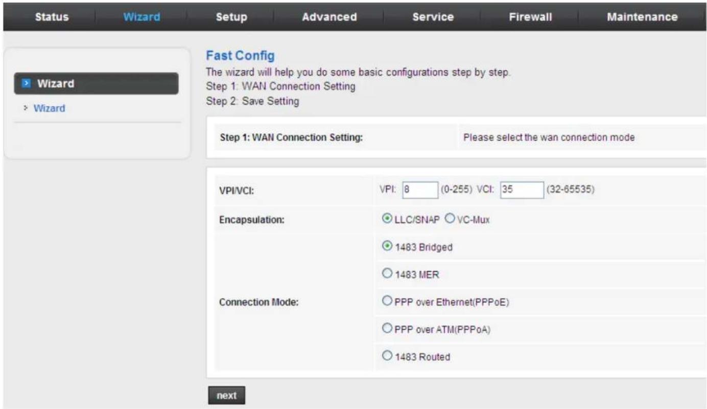
After setting, click Next and the page as shown in the following figure appears.
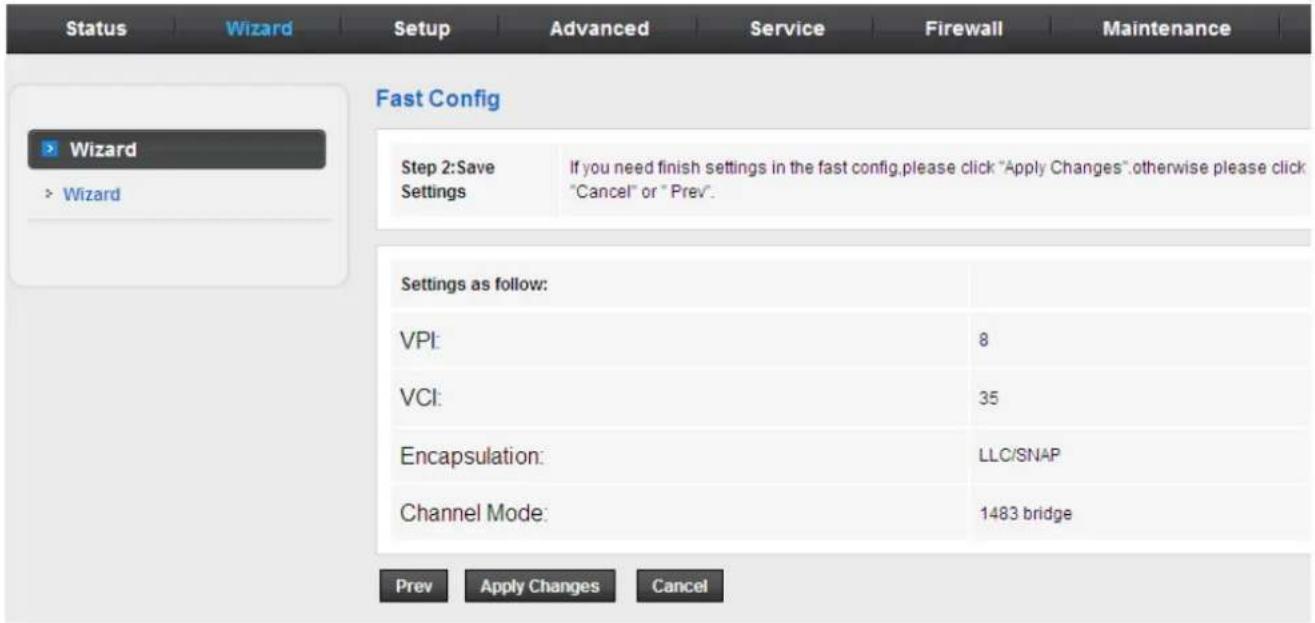
3.4 Setup
In the navigation bar, click Setup. The Setup page that is displayed contains WAN and LAN.
3.4.1 WAN
Choose Setup > WAN. The WAN page that is displayed contains WAN, Auto PVC, ATM and ADSL.
3.4.1.1 WAN
Click WAN in the left pane, the page shown in the following figure appears.
In this page, you can configure WAN interface of your router.
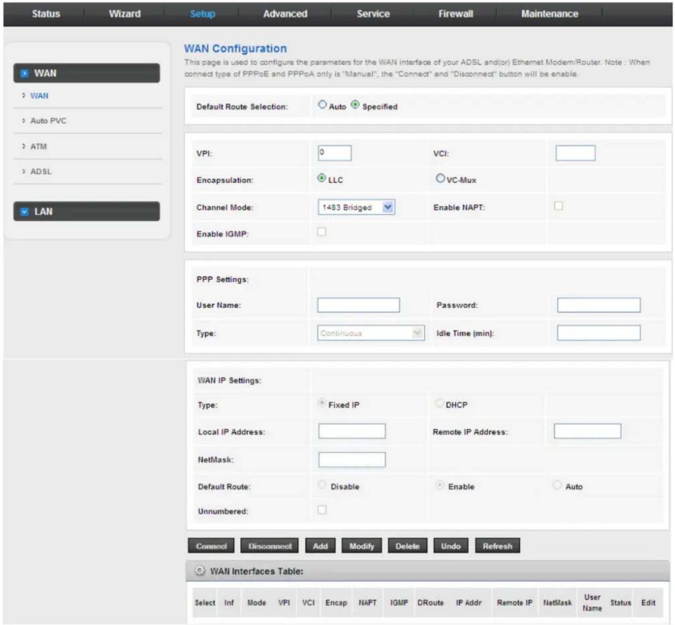
The following table describes the parameters on this page:
| Field Description | |
| Default Route Selection | You can select Auto or Specified. |
| VPI | The virtual path between two points in an ATM network, ranging from 0 to 255. |
| VCI | The virtual channel between two points in an ATM network, ranging from 32 to 65535 (1 to 31 are reserved for known protocols) |
| Encapsulation | You can choose LLC and VC-Mux. |
| Channel Mode | You can choose 1483 Bridged, 1483 MER, PPPoE, PPPoA, 1483 Routed or IPoA. |
| Enable NAPT | Select it to enable Network Address Port Translation (NAPT) function. If you do not select it and you want to access the Internet normally, you must add a route on the uplink equipment. Otherwise, the access to the Internet fails. Normally, it is enabled. |
| Enable IGMP | You can enable or disable Internet Group Management Protocol (IGMP) function. |
| PPP Settings | |
| User Name | Enter the correct user name for PPP dial-up, which is provided by your ISP. |
| Password | Enter the correct password for PPP dial-up, which is provided by your ISP. |
| Type | You can choose Continuous, Connect on Demand, or Manual. |
| Idle Time (min) | If set the type to Connect on Demand, you need to enter the idle timeout time. Within the preset minutes, if the router does not detect the flow of the user continuously, the router automatically disconnects the PPPoE connection. |
| WAN IP Settings | |
| Type | You can choose Fixed IP or DHCP.If select Fixed IP, you should enter the local IP address, remote IP address and subnet mask.If select DHCP, the router is a DHCP client, the WAN IP address is assigned by the remote DHCP server. |
| Local IP Address Enter the IP address of WAN interface provided by your ISP. | |
| Netmask Enter the subnet mask of the local IP address. | |
| Unnumbered Select this checkbox to enable IP unnumbered function. | |
| Add | After configuring the parameters of this page, click it to add new PVC into the Current ATM VC Table. |
| Modify | Select PVC in the Current ATM VC Table, and modify the parameters of this PVC. After finishing, click it to apply the settings of this PVC. |
| WAN Interfaces Table | This table shows the existed PVCs. It shows the interface name, channel mode, VPI/VCI, encapsulation mode, local IP address, remote IP address and other information. The maximum item of this table is eight. |
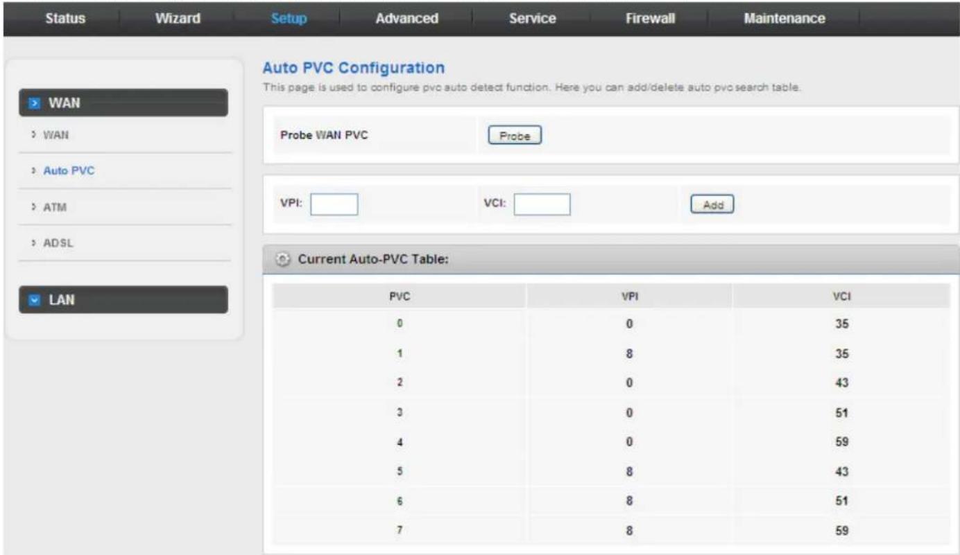
3.4.1.2 Auto PVC
Click Auto PVC in the left pane, page shown in the following figure appears. In this page, you can get a PVC automatically through detecting function, and add or delete the PVC that you do not want.
3.4.1.3 ATM
Click ATM in the left pane, the page shown in the following figure appears. In this page, you can configure the parameters of the ATM, including QoS, PCR, CDVT, SCR and MBS
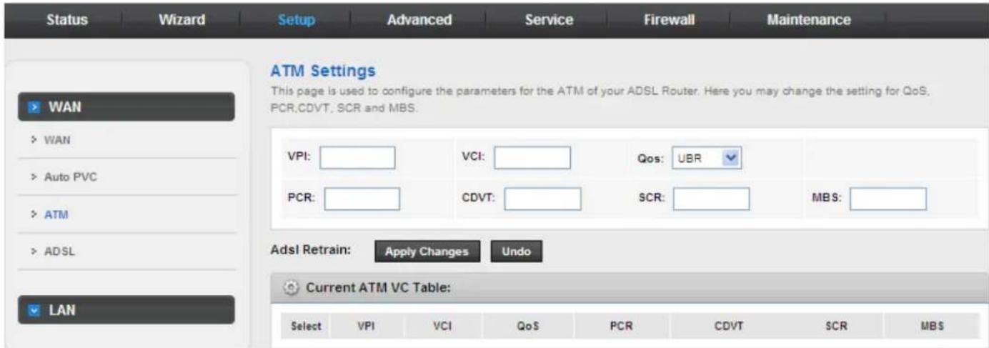
The following table describes the parameters of this page:
| Field Description | |
| VPI The virtual path identifier of the ATM PVC. | |
| VCI The virtual channel identifier of the ATM PVC. | |
| QoS | The QoS category of the PVC. You can choose UBR, CBR, nrt-VBR or rt-VBR. |
| PCR Peak cell | rate (PCR) is the maximum rate at which cells can be transmitted along a connection in the ATM network. Its value ranges from 1 to 65535. |
| CDVT | Cell delay variation tolerance (CDVT) is the amount of delay permitted between ATM cells(in microseconds). Its value ranges from 0 to 4294967295. |
| SCR | Sustained cell rate (SCR) is the maximum rate that traffic can pass over PVC without the risk of cell loss. Its value ranges from 0 to 65535. |
| MBS | Maximum burst size (MBS) is the maximum number of cells that can be transmitted at the PCR. Its value ranges from 0 to 65535. |
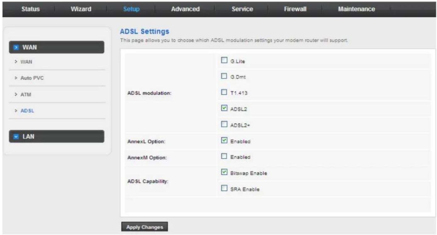
3.4.1.4 ADSL
Click ADSL in the left pane, the page shown in the following figure appears. In this page, you can select the DSL modulation. Mostly, you need to remain this factory default settings. The router supports these modulations: G.Lite, G.Dmt, T1.413, ADSL2 and ADSL2+. The router negotiates the modulation modes with the DSLAM.
3.4.2 LAN
Choose Setup > LAN. The LAN page that is displayed contains LAN, DHCP, DHCP Static and LAN IPv6.
3.4.2.1 LAN
Click LAN in the left pane, the page shown in the following figure appears.
In this page, you can change IP address of the router. The default IP address is 192.168.1.1, which is the private IP address of the router.
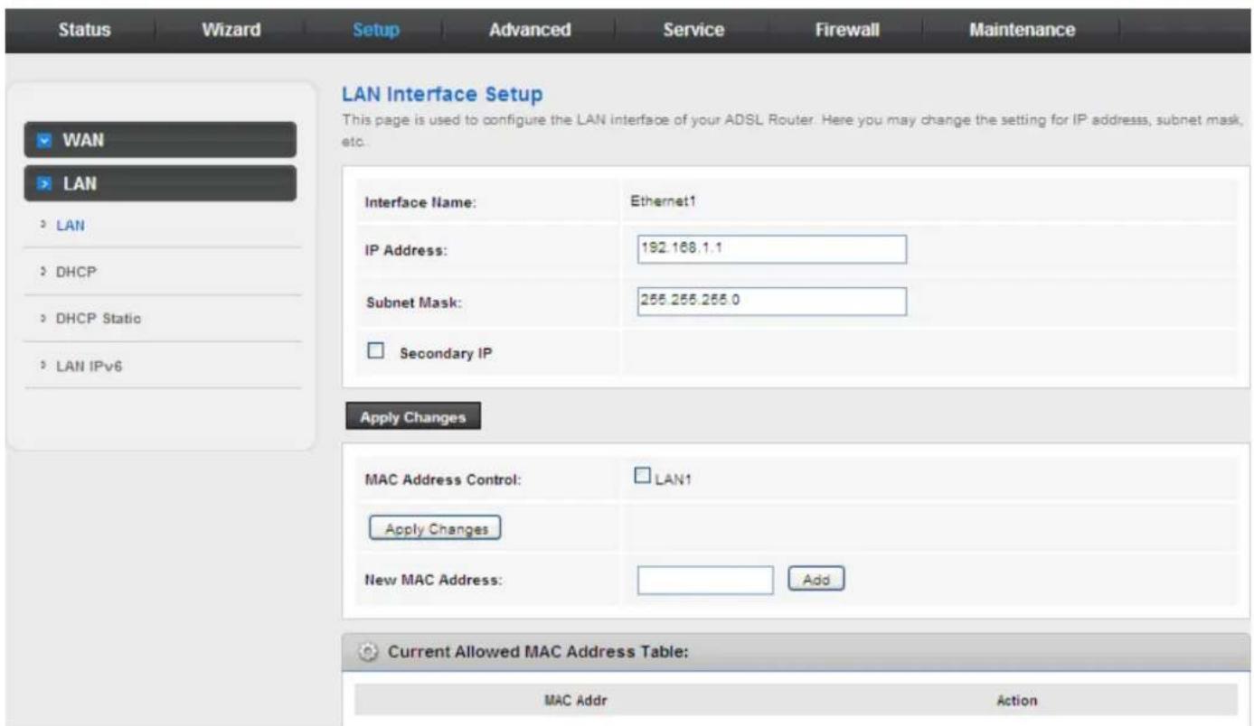
The following table describes the parameters of this page:
| Field Description | |
| IP Address | Enter the IP address of LAN interface. It is recommended to use an address from a block that is reserved for private use. This address block is 192.168.1.1-192.168.1.254. |
| Subnet Mask | Enter the subnet mask of LAN interface. The range of subnet mask is from 255.255.0.0-255.255.255.254. |
| Secondary IP | Select it to enable the secondary LAN IP address. The two LAN IP addresses must be in the different network. |
| MAC Address Control | It is the access control based on MAC address. When selecting it, the host whose MAC address is listed in the Current Allowed MAC Address Table can access the modem. |
| Add Enter MAC address, and then click it to add a new MAC address. | |
3.4.2.2 DHCP
Dynamic Host Configuration Protocol (DHCP) allows the individual PC to obtain the TCP/IP configuration from the centralized DHCP server. You can configure this router as a DHCP server or disable it. The DHCP server can assign IP address, IP default gateway, and DNS server to DHCP clients. This router can also act as a surrogate DHCP server (DHCP Relay) where it relays IP address assignment from an actual real DHCP server to clients. You can enable or disable DHCP server.
Click DHCP in the left pane, the page shown in the following figure appears.
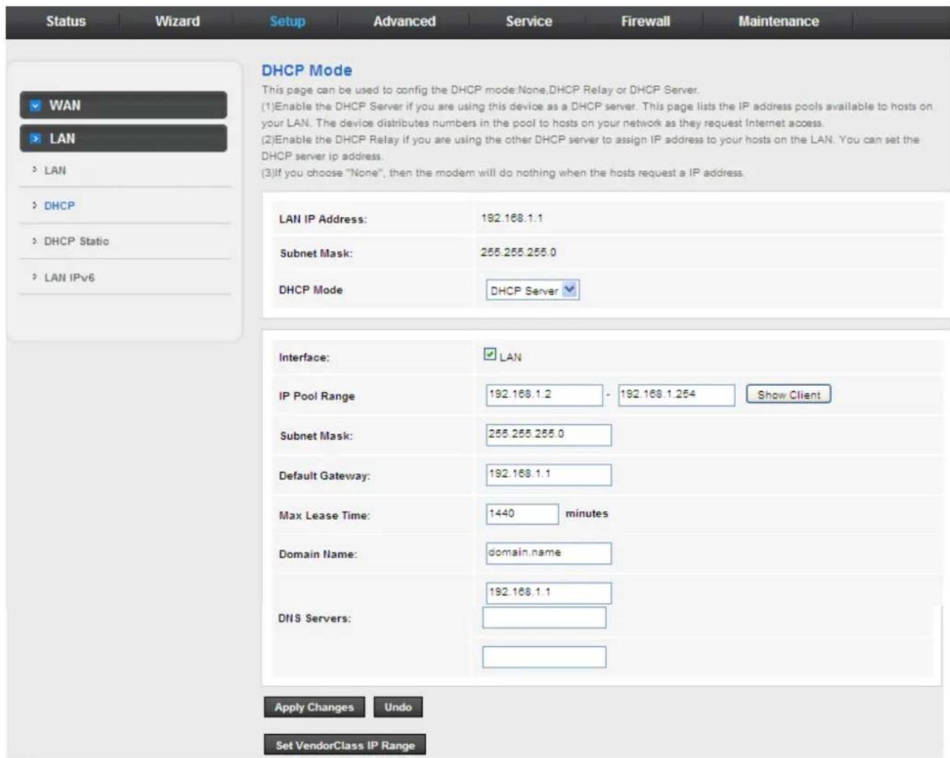
The following table describes the parameters on this page:
| Field Description | |
| DHCP Mode | If set to DHCP Server, the router can assign IP addresses, IP default gateway and DNS Servers to the host in Windows95, Windows NT and other operation systems that support the DHCP client. |
| IP Pool Range | It specifies the first and the last IP address in the IP address pool. The router assigns IP address that is in the IP pool range to the host. |
| Show Client | Click it, the Active DHCP Client Table appears. It shows IP addresses assigned to clients. |
| Default Gateway Enter the dedefault gateway of the IP address pool. | |
| Max Lease Time | The lease time determines the period that the host retains the assigned IP addresses before the IP addresses change. |
| Domain Name | Enter the domain name if you know. If you leave this blank, the domain name obtained by DHCP from the ISP is used. You must enter host name (system |
| Field Description | |
| name) on each individual PC. The domain name can be assigned from the router through the DHCP server. | |
| DNS Servers You can configure the DNS server IP addresses for DNS Relay. | |
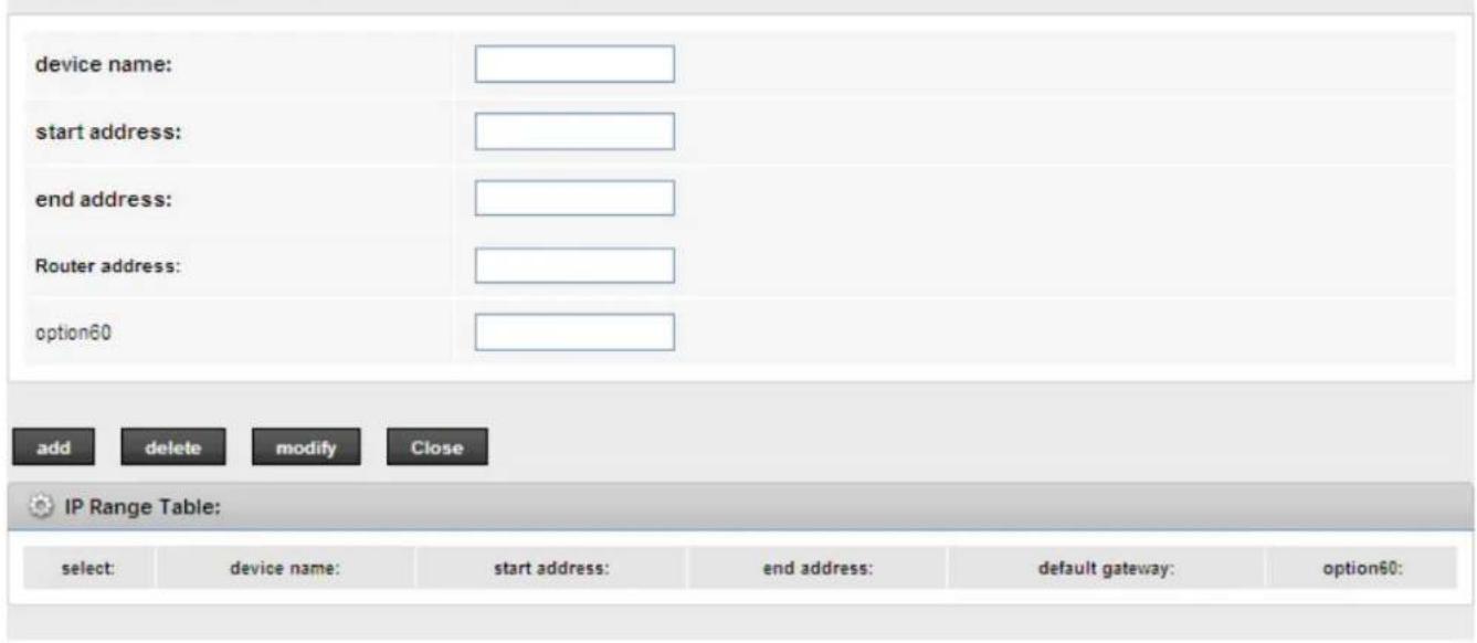
| Set Vendor Class IP Range | Click it, theDevice IP Range Tablepage appears. You can configure the IP address range based on the device type. |
Click Show Client on the DHCP Mode page and the page shown in the following figure appears. You can view the IP address assigned to each DHCP client.
Active DHCP Client Table
This table shows the assigned IP address, MAC address and time expired for each DHCP leased client.

Name
IP Address
MAC Address
Expiry(s)
Type
Refresh
Close
The following table describes the parameters and buttons on this page:
| Field | Description |
| IP Address It displays the IP address assigned to the DHCP client from the router. | |
| MAC Address | It displays the MAC address of the DHCP client.Each Ethernet device has a unique MAC address. The MAC address is assigned at the factory and it consists of six pairs of hexadecimal character, for example, 00-A0-C5-00-02-12. |
| Expiry (s) | It displays the lease time. The lease time determines the period that the host retains the assigned IP addresses before the IP addresses change. |
| Refresh Click it to refresh this page. | |
| Close Click it to close this page. | |
Click Set Vendor Class IP Range on the DHCP Mode page and the page as shown in the following figure appears. On this page, you can configure the IP address range based on the device type.
Device IP Range Table
This page is used to configure the IP address range based on device type.
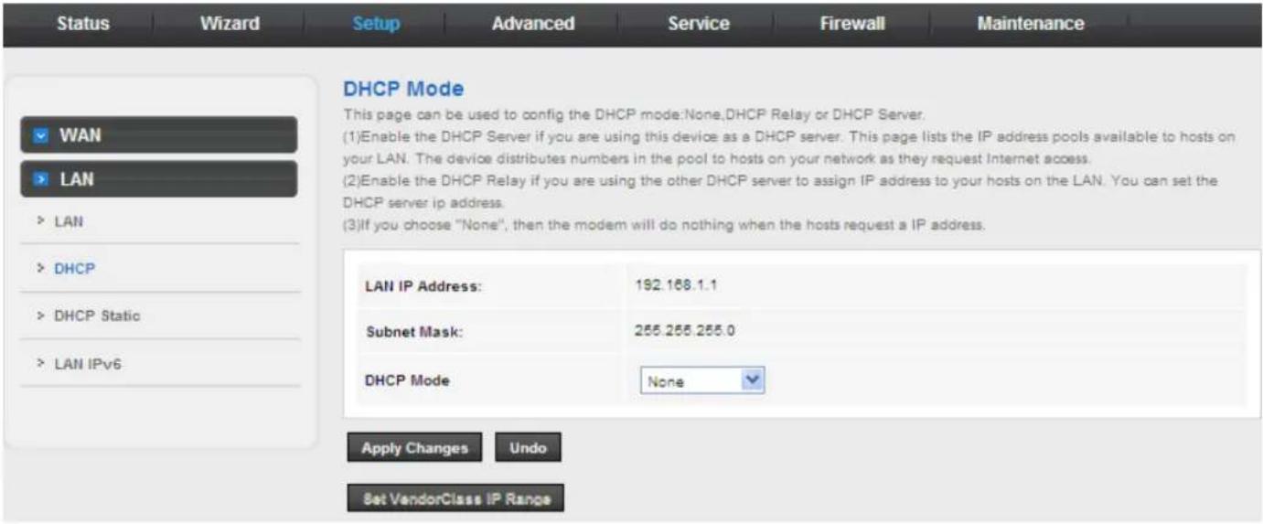
In the DHCP Mode field, choose None and the page shown in the following figure appears.
In the DHCP Mode field, choose DHCP Relay and the page shown in the following figure appears.
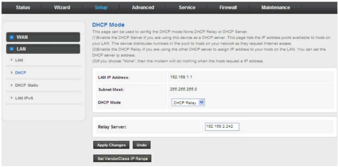
The following table describes the parameters and buttons on this page:
| Field Description | |
| DHCP Mode | If set to DHCP Relay, the router acts a surrogate DHCP Server and relays the DHCP requests and responses between the remote server and the client. |
| Relay Server Enter the DHCP server address provided by your ISP. | |
| Apply Changes Click it to save the settings of this page. | |
| Undo Click it to refresh this page. | |
3.4.2.3 DHCP Static IP
Click DHCP Static IP in the left pane and the page shown in the following figure appears. You can assign the IP addresses on the LAN to the specific individual PCs based on their MAC address.
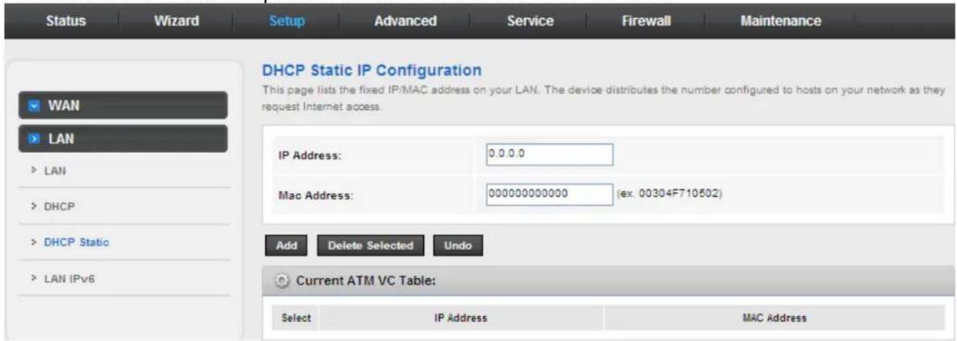
The following table describes the parameters and buttons on this page:
| Field Description | |
| IP Address Enter the specified IP address in the IP pool range, which is assigned to the host. | |
| MAC Address Enter the MAC address of a host on the LAN. | |
| Add After entering the IP address | and MAC address, click it. A row will be added in the DHCP Static IP Table. |
| Delete Selected | Select a row in the DHCP Static IP Table, then click it, this row is deleted. |
| Undo Click it to refresh this page. | |
| Current ATM VC Table It shows the assigned IP address based on the MAC address. | |
3.4.2.4 LAN IPv6
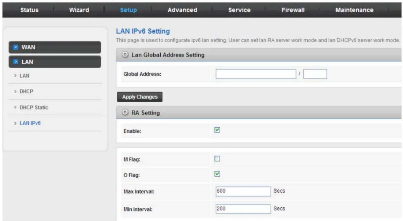
In this page, you can configure the LAN IPv6. Choose Setup > LAN > LAN IPv6. The IPv6 LAN setting page as shown in the following figure appears:
3.5 Advanced
In the navigation bar, click Advanced. In the Advanced page that is displayed contains Route, NAT, QoS, TR-069 and Others.
3.5.1 Routing
Choose Advance > Routing, and this page contains Static Route and RIP.
3.5.1.1 Static Route
Click Static Route in the left pane, and the page shown in the following figure appears. This page is used to configure the routing information. You can add or delete IP routes.
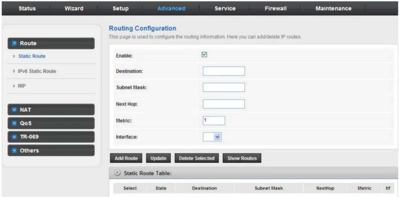
The following table describes the parameters and buttons of this page:
| Field Description | |
| Enable Select it to use | static IP routes. |
| Destination Enter the IP address of the destination device. | |
| Subnet Mask Enter the subnet mask of the destination device. | |
| Next Hop Enter the IP address of the next hop in the IP route to the destination device. | |
| Metric The metric cost for the destination. | |
| Interface The interface for the specified route. | |
| Add Route | Click it to add the new static route to the Static Route Table. |
| Update | Select a row in the Static Route Table and modify the parameters. Then click it to save the settings temporarily. |
| Delete Selected | Select a row in the Static Route Table and click it to delete the row. |
| Show Routes | Click it, the IP Route Table appears. You can view a list of destination routes commonly accessed by your network. |
| Static Route Table | A list of the previously configured static IP routes. |
Click Show Routes, the page shown in the following figure appears. The table shows a list of destination routes commonly accessed by your network.
IP Route Table
This table shows a list of destination routes commonly accessed by your network.
| Destination | Subnet Mask | NextHop | Interface |
| 192.168.1.1 | 255.255.255.255 | * | e1 |
| Refresh | Close |
3.5.1.2 IPv6 Static Route
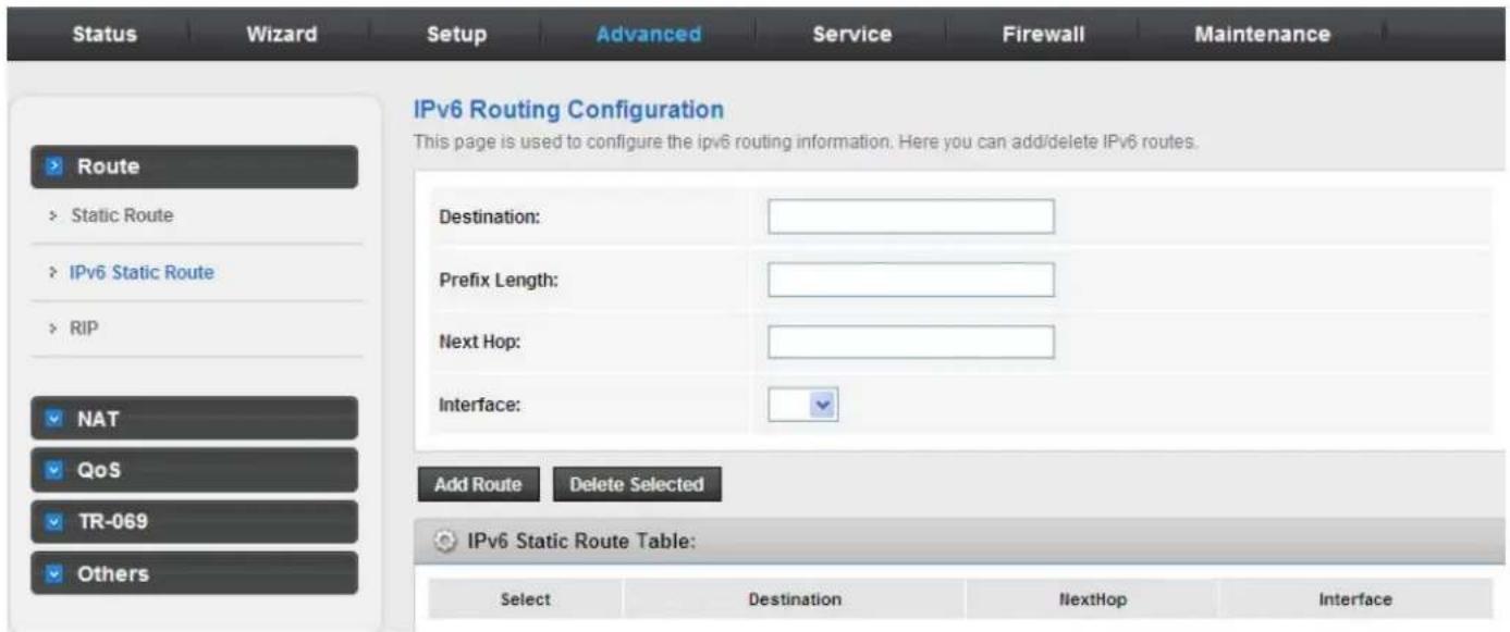
Click IPv6 Static Route in the left pane, and the page shown in the following figure appears. This page is used to configure the routing information. You can add or delete IP routes.
3.5.1.3 RIP
Click RIP in the left pane, the page shown in the following figure appears. If you are using this device as a RIP-enabled router to communicate with others using Routing Information Protocol (RIP), enable RIP. This page is used to select the interfaces on your devices that use RIP, and the version of the protocol used.
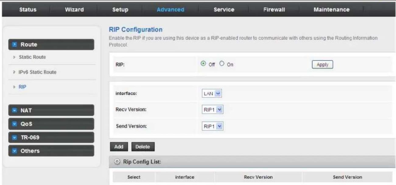
The following table describes the parameters and buttons of this page:
| Field Description | |
| RIP | You can select OFF or ON. In this example, OFF is selected. |
| Apply Click it to save the settings of this page. | |
| Interface Choose the router interface that uses RIP. | |
| Recv Version Choose the interface version that receives RIP messages. You can choose RIP1, RIP2, or Both.Choose RIP1, indicates the router receives RIP v1 messages.Choose RIP2, indicates the router receives RIP v2 messages.Choose Both, indicates the router receives RIP v1 and RIP v2 messages. | |
| Send Version | The working mode for sending RIP messages. You can choose RIP1 or RIP2.Choose RIP1 indicates the router broadcasts RIP1 messages only.Choose RIP2 indicates the router multicasts RIP2 messages only. |
| Add | Click it to add the RIP interface to the Rip Config List. |
| Delete | Select a row in the Rip Config List and click it to delete the row. |
3.5.2 NAT
Choose Advanced > NAT and the page shown in the following figure appears. The page displayed contains DMZ, Virtual Server, ALG, NAT Exclude IP, Port Trigger, FTP ALG Port, and NAT IP Mapping.
3.5.2.1 DMZ
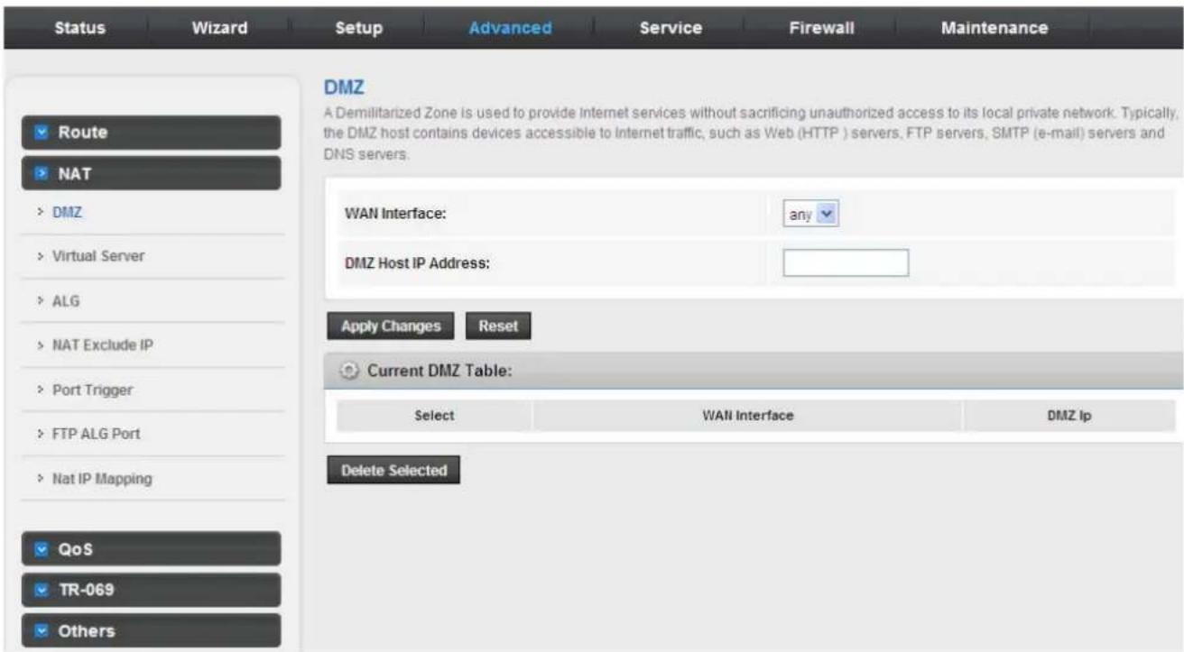
Demilitarized Zone (DMZ) is used to provide Internet services without sacrificing unauthorized access to its local private network. Typically, the DMZ host contains devices accessible to Internet traffic, such as web (HTTP) servers, FTP servers, SMTP (e-mail) servers and DNS servers.
Click DMZ in the left pane, the page shown in the following figure appears.
The following describes how to configure manual DMZ.
Enter an IP address of the DMZ host.
Click Apply Changes to save the settings of this page temporarily.
3.5.2.2 Virtual Server 3.5.2.2 Virtual Server
Click Virtual Server in the left pane and the page shown in the following figure appears.
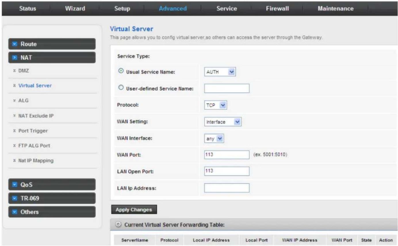
The following table describes the parameters of this page.
| Field Description | |
| Service Type | You can select the common service type, for example, AUTH, DNS or FTP. You can also define a service name.If you select Usual Service Name, the corresponding parameter has the default settings.If you select User-defined Service Name, you need to enter the corresponding parameters. |
| Protocol | Choose the transport layer protocol that the service type uses. You can choose TCP or UDP. |
| WAN Setting | You can choose Interface or IP Address. |
| WAN Interface Choose the WAN interface that will apply virtual server. | |
| WAN Port Choose the access port on the WAN. | |
| LAN Open Port Enter the port number of the specified service type. | |
| LAN IP Address | Enter the IP address of the virtual server. It is in the same network segment with LAN IP address of the router. |
3.5.2.3 ALG
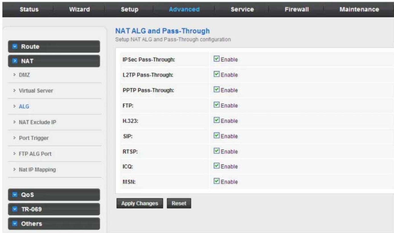
Click ALG in the left pane, and the page shown in the following figure appears. Choose the NAT ALG and Pass-Through options, and then click Apply Changes.
3.5.2.4 NAT Exclude IP
Click NAT Exclude IP in the left pane, and the page shown in the following figure appears.
In the page, you can configure some source IP addresses which use the purge route mode when accessing internet through the specified interface.
3.5.2.5 Port Trigger
Click Port Trigger in the left pane and the page shown in the following figure appears.
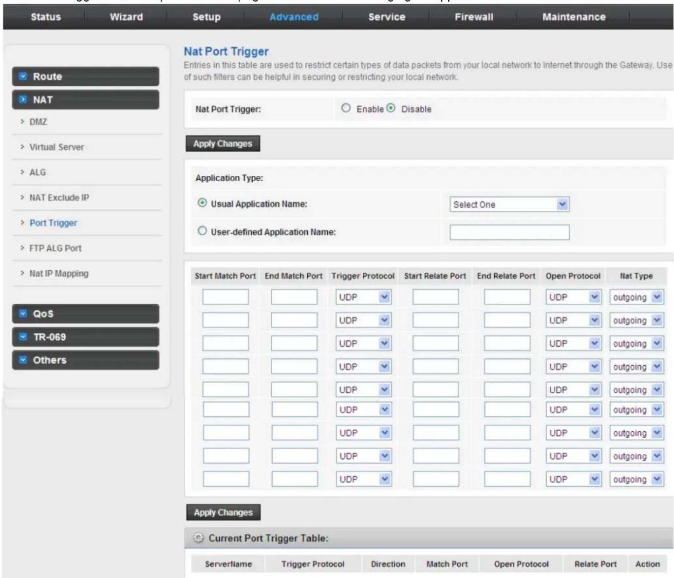
Click the Usual Application Name drop-down menu to choose the application you want to setup for port triggering. When you have chosen an application the default Trigger settings will populate the table below.
If the application you want to setup isn't listed, click the User-defined Application Name radio button and type in a name for the trigger in the Custom application field. Configure the Start Match Port, End Match Port, Trigger Protocol, Start Relate Port, End Relate Port, Open Protocol and Nat type settings for the port trigger you want to configure.
When you have finished click the Apply changes button.
3.5.2.6 FTP ALG Port
Click FTP ALG Port in the left pane, the page shown in the following figure appears. The common port for FTP connection is port 21, and a common ALG monitors the TCP port 21 to ensure NAT pass-through of FTP. By enabling this function, when the FTPserver connection port is not a port 21, the FTP ALG module will be informed to monitor other TCP ports to ensure NAT pass-through of FTP.
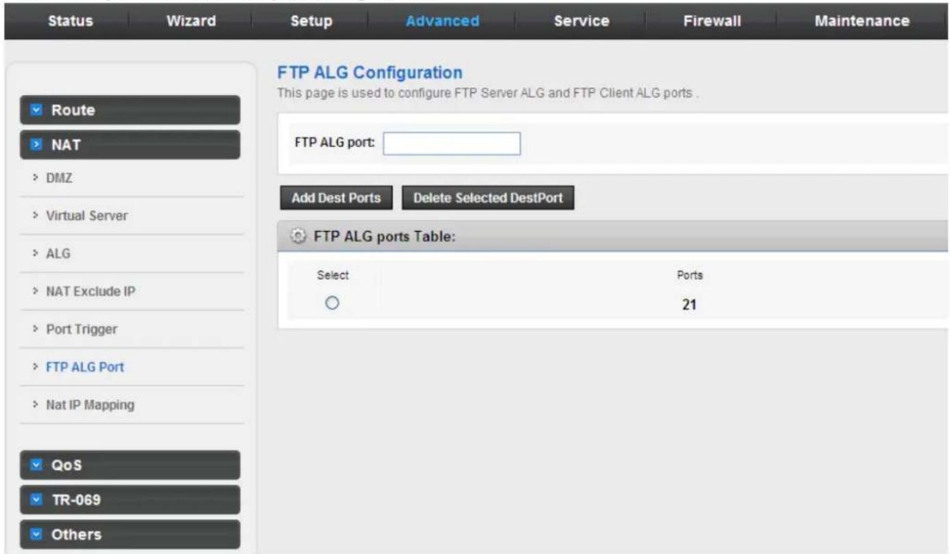
The following table describes the parameters and buttons of this page:
| Field Description | |
| FTP ALG port Set an FTP ALG port. | |
| Add Dest Ports Add a port configuration. | |
| Delete Selected DestPort Delete a selected port configuration from the list. | |
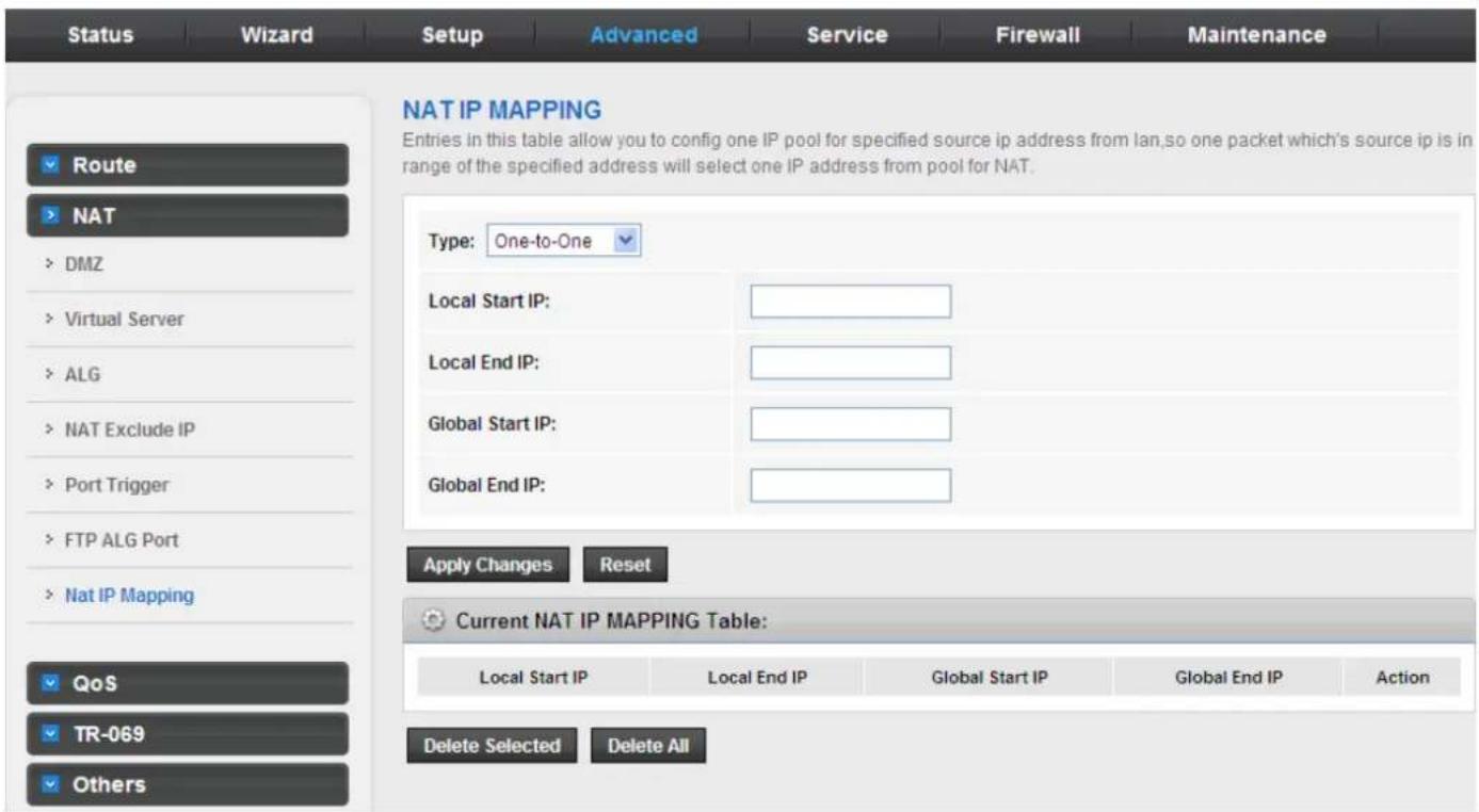
3.5.2.7 NAT IP Mapping
NAT is short for Network Address Translation. The Network Address Translation Settings window allows you to share one WAN IP address for multiple computers on your LAN.
Click NAT IP Mapping in the left pane, the page shown in the following figure appears
Entries in this table allow you to configure one IP pool for specified source IP address from LAN, so one packet whose source IP is in range of the specified address will select one IP address from the pool for NAT.
3.5.3 QoS
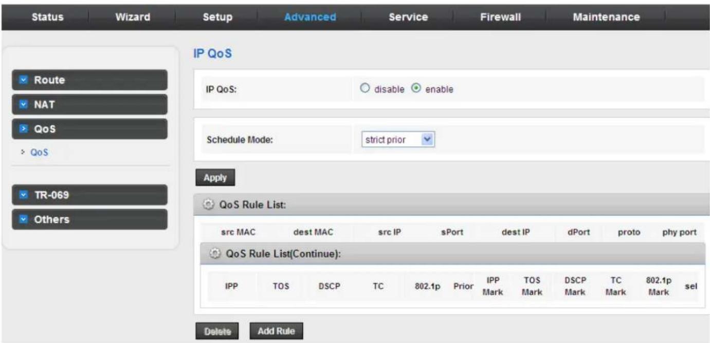
Choose Advanced > QoS, and the page shown in the following figure appears. Entries on the QoS Rule List are used to assign the precedence for each incoming packet based on physical LAN port, TCP/UDP port number, source IP address, destination IP address and other information.
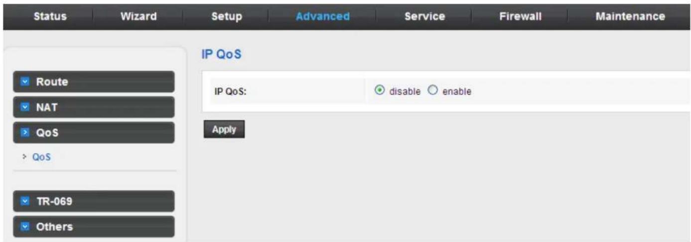
Enable QoS and click Apply to enable IP QoS function.
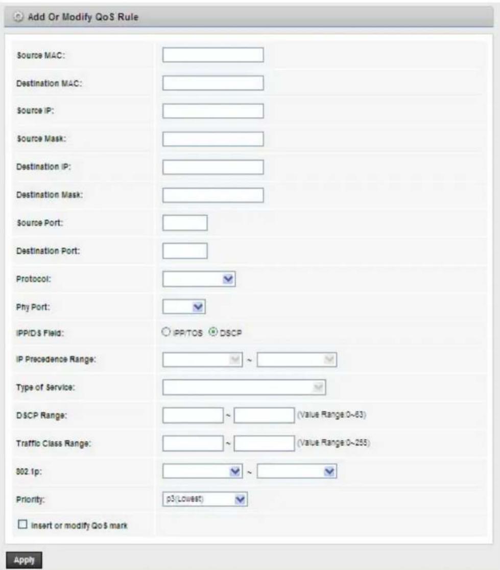
Click add rule to add a new IP QoS rule.
The page shown in the following figure appears.
The following table describes the parameters and buttons of this page:
| Field Description | |
| QoS Select to enable or disable IP QoS function. You need to enable IP QoS if you want to configure the parameters of this page. | |
| QoS Policy | You can choose stream based, 802.1p based, or DSCP based. |
| Schedule Mode | You can choose strict prior or WFQ (4:3:2:1). |
| Source IP The IP address of the source data packet. | |
| Source Mask The subnet mask of the source IP address. | |
| Destination IP The IP address of the destination data packet. | |
| Destination Mask The subnet mask of the destination IP address. | |
| Source Port The port of the source data packet. | |
| Destination Port The port of the destination data packet. | |
| Protocol | The protocol responds to the IP QoS rules. You can choose TCP, UDP, or ICMP. |
| Phy Port | The LAN interface responds to the IP QoS rules. |
| Set priority | The priority of the IP QoS rules. P0 is the highest priority and P3 is the lowest. |
| Delete | Select a row in the QoS rule list and click it to delete the row. |
| Delete all | Select all the rows in the QoS rule list and click it to delete the rows. |
3.5.4 TR-069
Choose Advanced > TR-069 and the page shown in the following page appears. In this page, you can configure the TR-069 CPE.
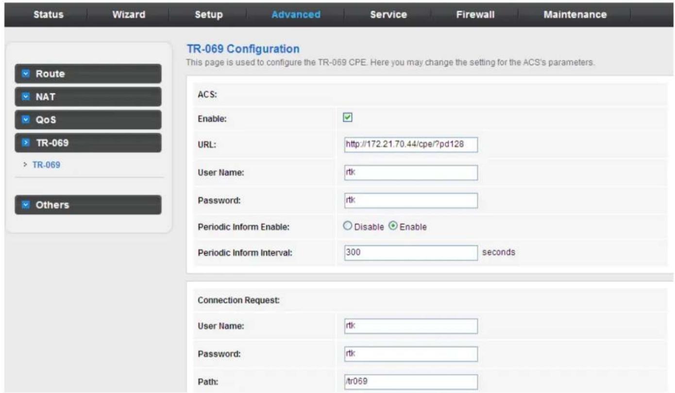
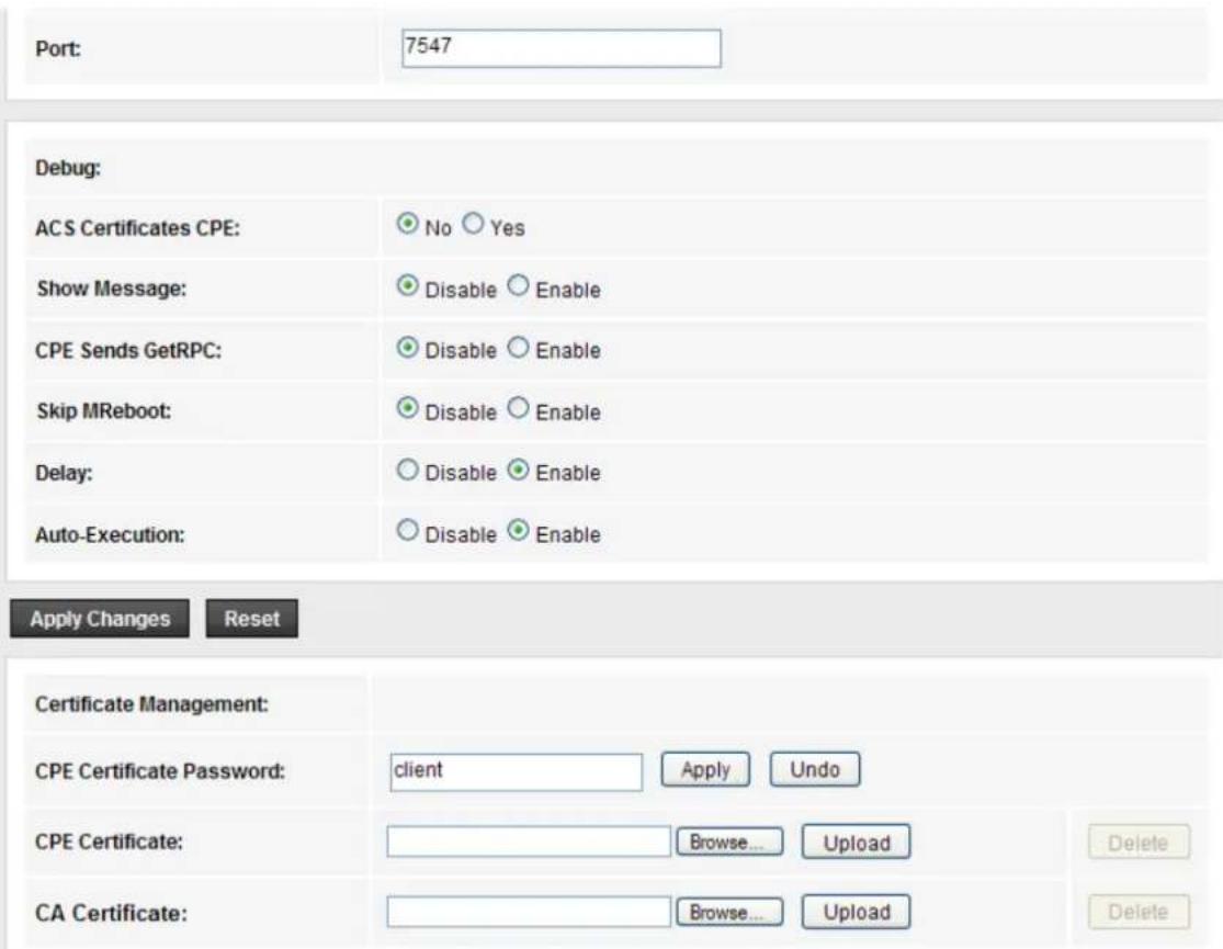
The following table describes the parameters of this page:
| Field Description | |
| ACS | |
| URL The URL of the auto-configuration server to connect to. | |
| User Name The user name for logging in to the ACS. | |
| Password The password for logging in to the ACS. | |
| Periodic Inform Enable | Select Enable to periodically connect to the ACS to check whether the configuration updates. |
| Periodic Inform Interval Specify the amount of time between connections to ACS. | |
| Connection Request | |
| User Name The connection username provided by TR-069 service. | |
| Password The connection password provided by TR-069 service. | |
| Debug | |
| Show Message Select Enable to display ACS SOAP messages on the serial console. | |
| CPE sends GetRPC | Select Enable, the router contacts the ACS to obtain configuration updates. |
| Skip MReboot Specify whether to send an MReboot event code in the inform message. | |
| Delay Specify whether to start the TR-069 program after a short delay. | |
| Auto-Execution Specify whether to automatically start the TR-069 after the router is powered on. | |
3.5.5.Others
Choose Advance > Others, and the page shown in the following figure appears. The page displayed contains Bridge Setting, Client Limit, Tunnel and Others.
3.5.5.1 Bridge Setting
Choose Advance > Others > Bridge Setting, and the page shown in the following figure appears. This page is used to configure the bridge parameters. You can change the settings or view some information on the bridge and its attached ports.
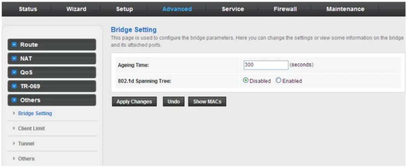
The following table describes the parameters and button of this page:
| Field Description | |
| Aging Time | If the host is idle for 300 seconds (default value), its entry is deleted from the bridge table. |
| 802.1d Spanning Tree | You can select Disable or Enable.Select Enable to provide path redundancy while preventing undesirable loops in your network. |
| Show MACs Click it to show | a list of the learned MAC addresses for the bridge. |
Click Show MACs, and the page shown in the following figure appears. This table shows a list of learned MAC addresses for this bridge.
| Forwarding Table | |||
| MAC Address | Port | Type | Aging Time |
| 01:80:c2:00:00:00 | 0 | Static | 300 |
| 00:02:b3:03:03:00 | 1 | Dynamic | 270 |
| 00:30:4f:00:28:35 | 1 | Dynamic | 300 |
| 00:0e:c6:87:72:01 | 1 | Dynamic | 270 |
| 01:00:5e:00:00:09 | 0 | Static | 300 |
| 00:16:d4:ff:d2:e3 | 1 | Dynamic | 150 |
| 00:30:4f:91:dd:2b | 1 | Dynamic | 150 |
3.5.5.2 Client Limit
Choose Advance > Others > Client Limit, and the page shown in the following figure appears. This page is used to configure the capability of forcing how many devices can access to the Internet.
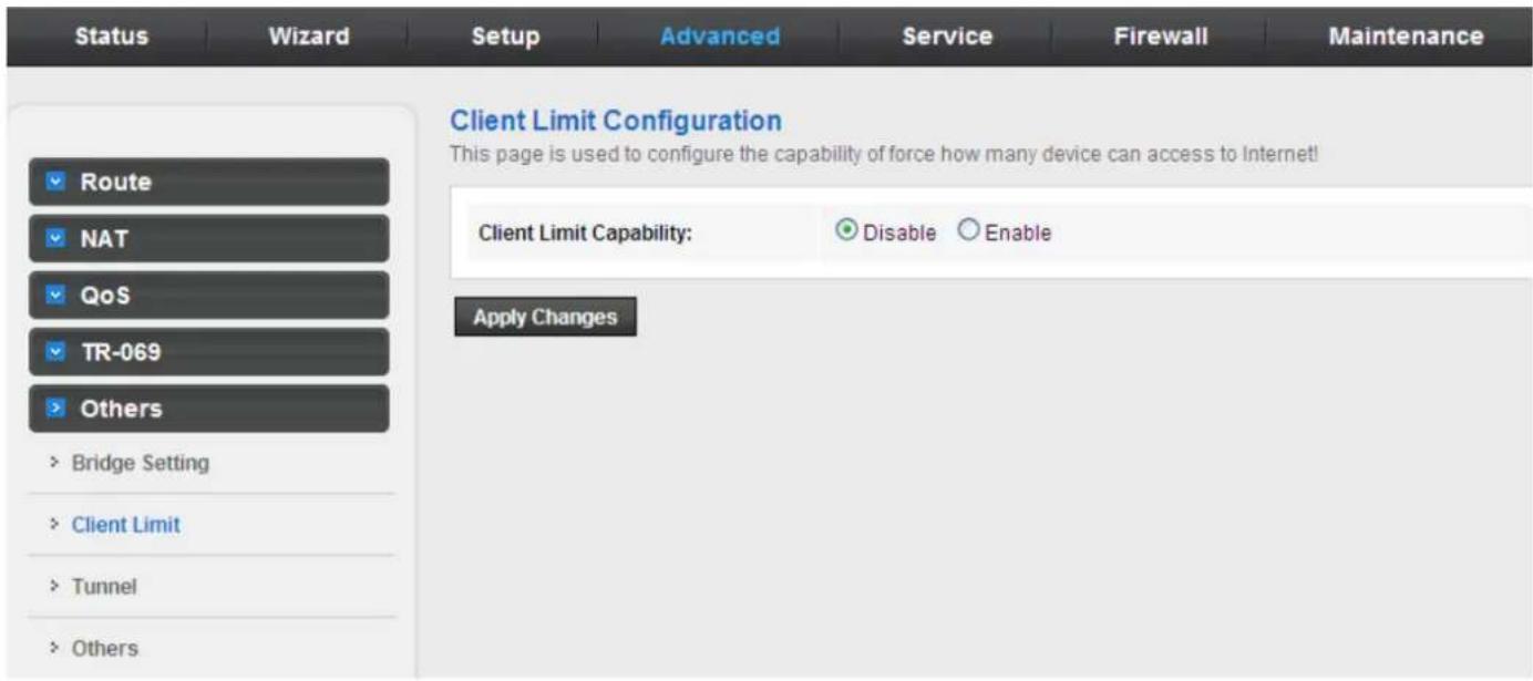
3.5.5.3 Tunnel
Choose Advance > Others > Tunnel, and the page shown in the following figure appears. This page is used to configure the IPv6 with LAN to transfer IPv4.
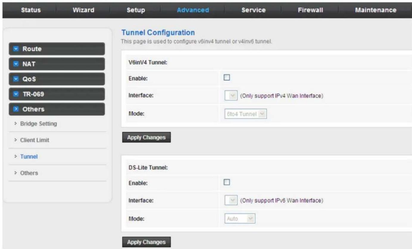
3.5.5.4 Others
Choose Advanced > Others > Others in the left pane, and the page shown in the following figure appears. You can enable half bridge so that the PPPoE or PPPoA connection will set to Continuous.
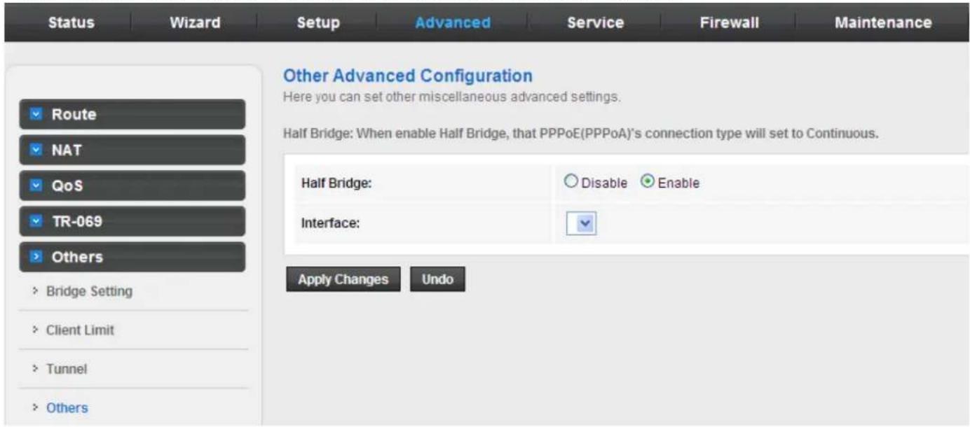
3.6 Service
In the navigation bar, click Service. On the Service page that is displayed contains IGMP, UPnP, SNMP DNS, and DDNS.
3.6.1 IGMP
3.6.1.1 IGMP Proxy
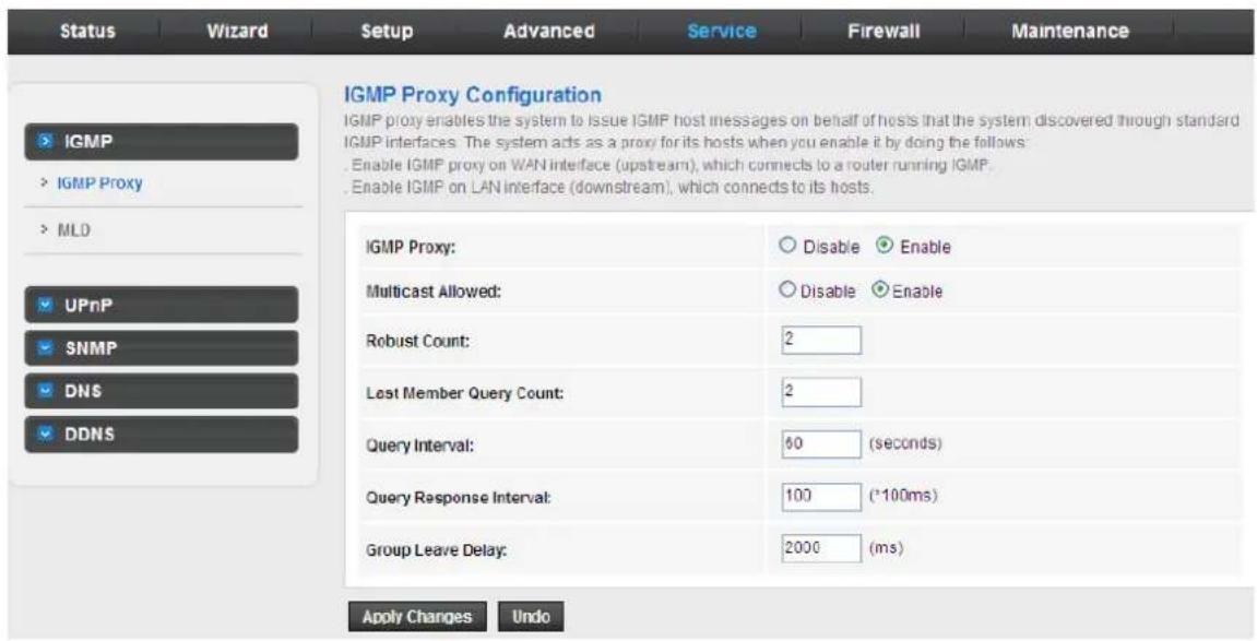
Choose Service > IGMP and the page shown in the following figure appears. IGMP proxy enables the system to issue IGMP host messages on behalf of hosts that the system discovered through standard IGMP interfaces. The system acts as a proxy for its hosts after you enable it.
3.6.1.2 MLD
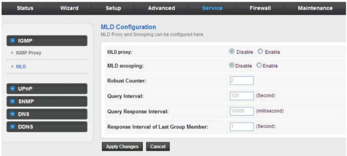
MLD means Multicast Listener Discovery, its component of the IPv6. MLD is used by IPv6 routers for discovering multicast listeners on a directly attached link, much like IGMP is used in IPv4.
3.6.2 UPNP
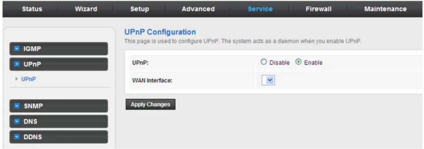
Choose Service > UPnP and the page shown in the following figure appears. This page is used to configure UPnP. The system acts as a daemon after you enable it.
3.6.3 SNMP
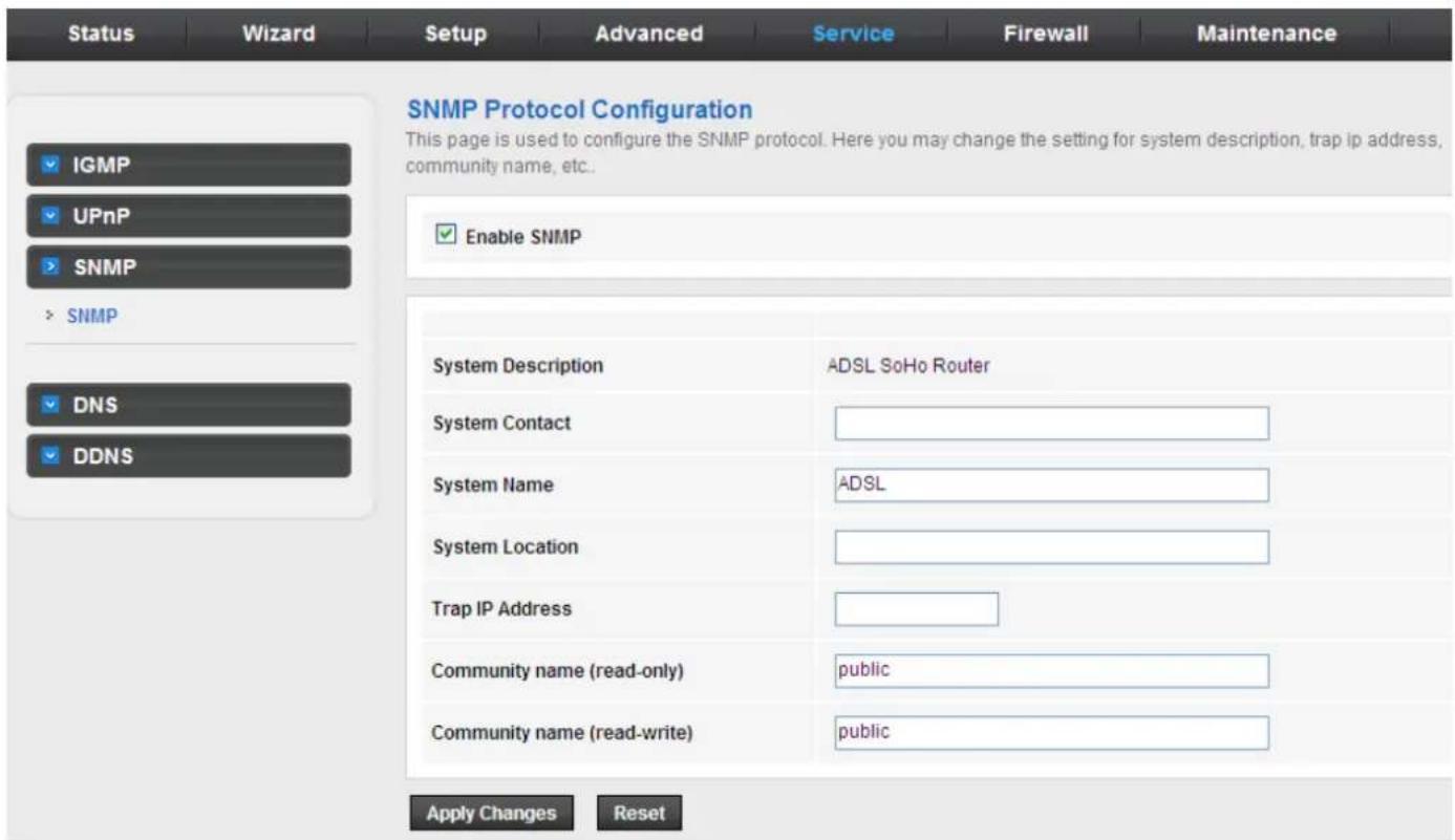
Choose Service > SNMP, click Enable SNMP, and the page shown in the following figure appears. You can configure the SNMP parameters.
The following table describes the parameters of this page:
| Field | Description |
| Enable SNMP | Select it to enable SNMP function. You need to enable SNMP, and then you can configure the parameters of this page. |
| Trap IP Address | Enter the trap IP address. The trap information is sent to the corresponding host. |
| Community Name (Read-only) | The network administrators must use this password to read the information of this router. |
| Community Name (Read-Write) | The network administrators must use this password to configure the information of the router. |
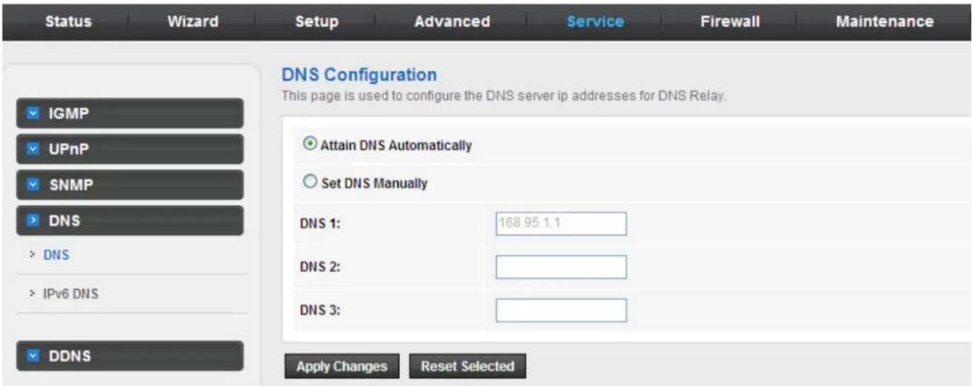
3.6.4 DNS
Domain Name System (DNS) is an Internet service that translates the domain name into IP address. Because the domain name is alphabetic, it is easier to remember. The Internet, however, is based on IP addresses. Every time you use a domain name, DNS translates the name into the corresponding IP address. For example, the domain name www.example.com might be translated to 198.105.232.4. The DNS has its own network. If one DNS server does not know how to translate a particular domain name, it asks another one, and so on, until the correct IP address is returned.
Choose Service > DNS. The DNS page that is displayed contains DNS and IPv6 DNS.
3.6.4.1 DNS
Click DNS in the left pane and the page shown in the following figure appears.
3.6.4.2 IPv6 DNS
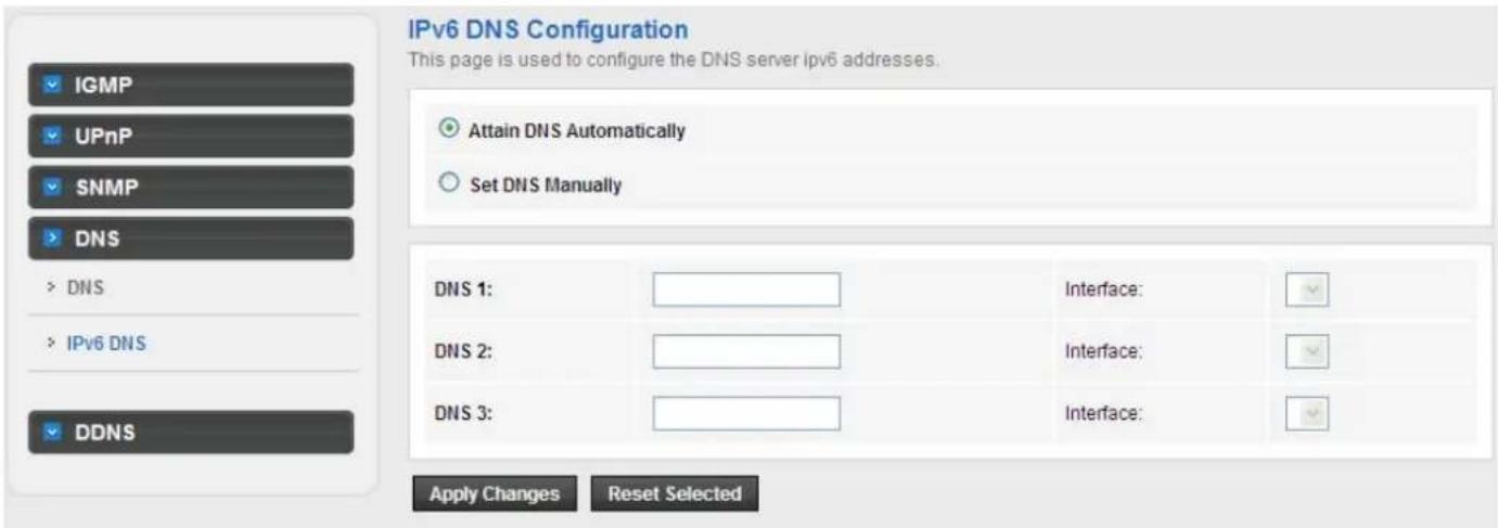
The following table describes the parameters and buttons on this page:
| Field Description | |
| Attain DNS Automatically | Select it, the router accepts the first received DNS assignment from one of the PPPoA, PPPoE or MER enabled PVC(s) during the connection establishment. |
| Set DNS Manually | Select it and enter the IP addresses of the primary and secondary DNS server. |
| Apply Changes Click | it to save the settings of this page. |
| Reset Selected Click | it to start configuring the parameters on this page. |
3.6.5 DDNS
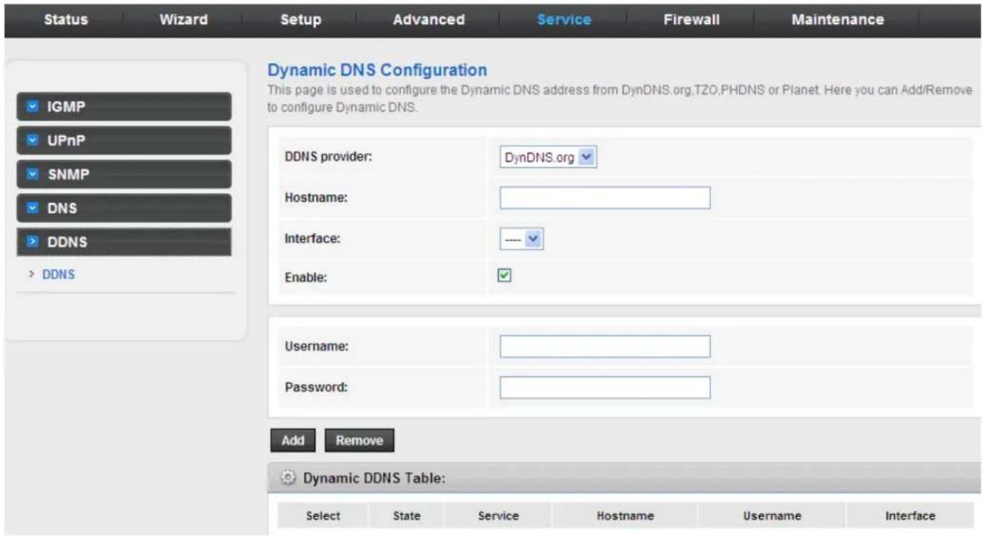
Click DDNS in the left pane and the page shown in the following figure appears. This page is used to configure the dynamic DNS address from DynDNS.org, TZO or Planet. You can add or remove to configure dynamic DNS.
The Planet DDNS is free for customer.
The following table describes the parameters on this page:
| Field Description | |
| DDNS provider | Choose the DDNS provider name. You can choose DynDNS.org, TZO or Planet. |
| Host Name The DDNS identifier. | |
| Interface The WAN interface of the router. | |
| Enable Enable or disable DDNS function. | |
| Username The name provided by DDNS provider. | |
| Password The password provided by DDNS provider. | |
| Email The email provided by DDNS provider. | |
| Key The key provided by DDNS provider. | |
3.7 Firewall
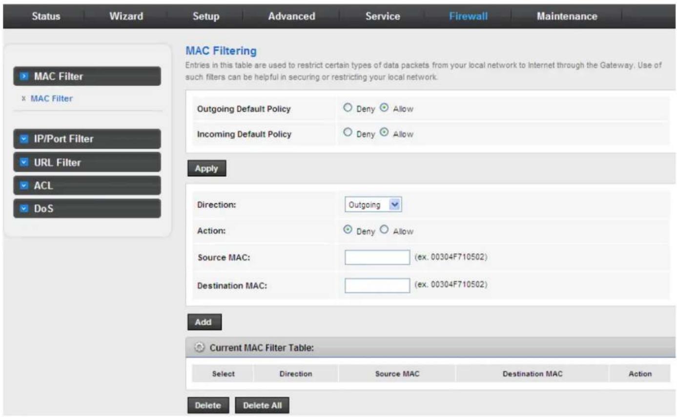
Choose Service > Firewall and the Firewall page that is displayed contains MAC Filter, IP/Port Filter, URL Filter, ACL and DoS.
3.7.1 MAC Filter
Click MAC Filter in the left pane and the page shown in the following figure appears. Entries in the table are used to restrict certain types of data packets from your local network to Internet through the gateway. These filters are helpful in securing or restricting your local network.
3.7.2 IP/Port Filter
3.7.2.1 IP/Port Filter
Click IP/Port Filter in the left pane and the page shown in the following figure appears. Entries in the table are used to restrict certain types of data packets through the gateway. These filters are helpful in securing or restricting your local network.
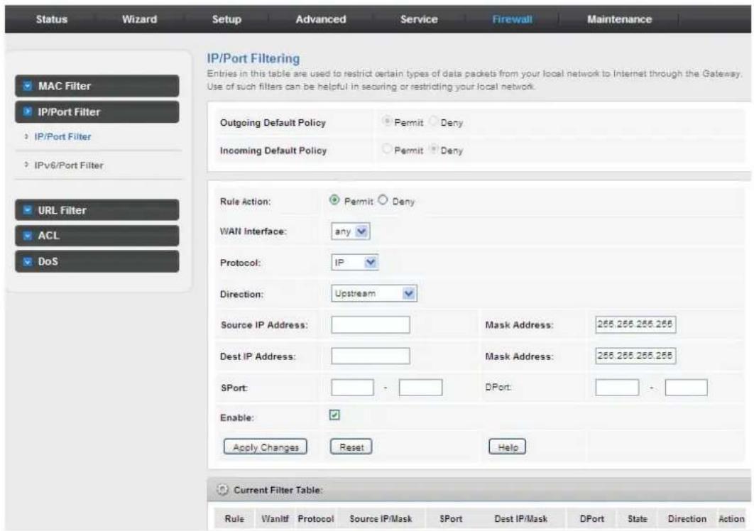
3.7.2.2 IPV6/Port Filter
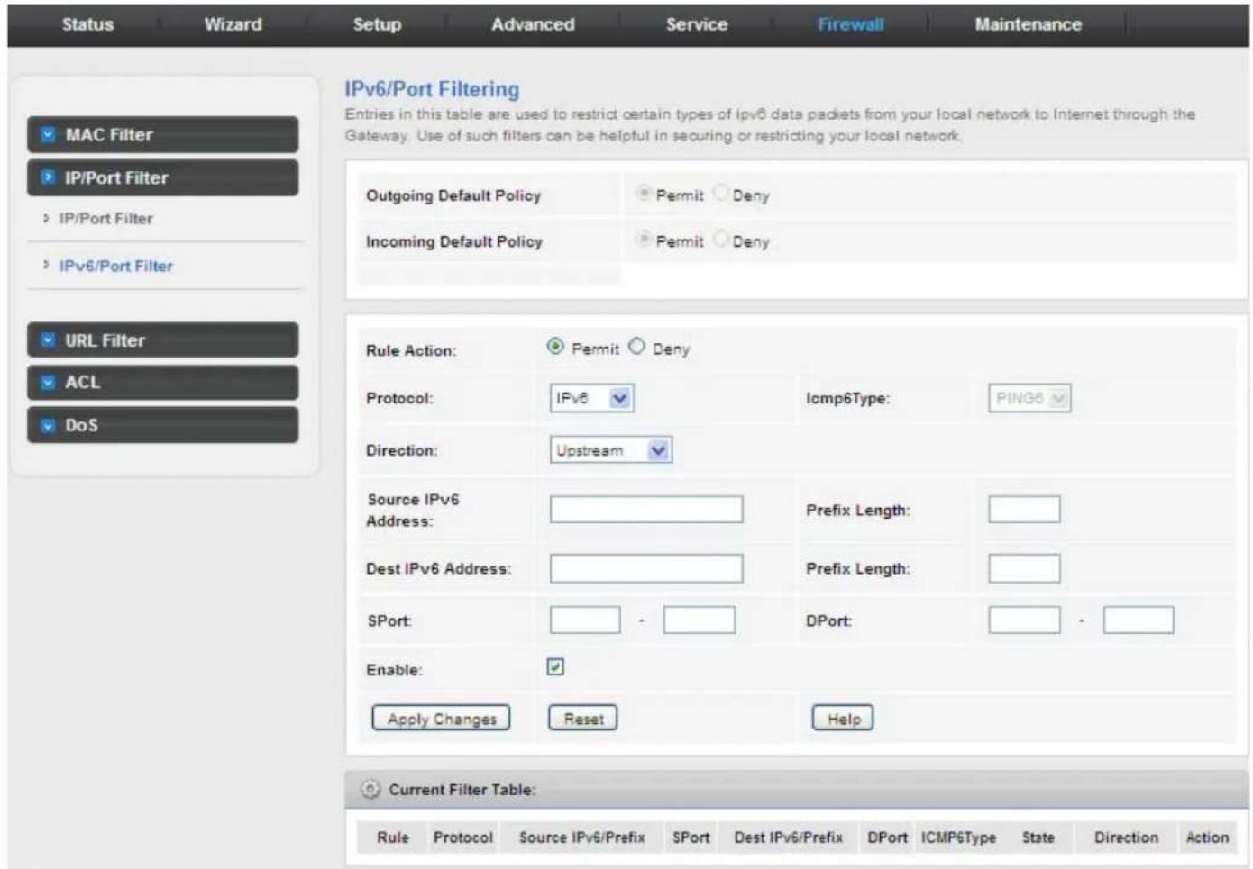
3.7.3 URL Filter
Click URL Filter in the left pane and the page shown in the following figure appears. This page is used to block a fully qualified domain name, such as tw.yahoo.com and filtered keyword. You can add or delete FQDN and filtered keyword.
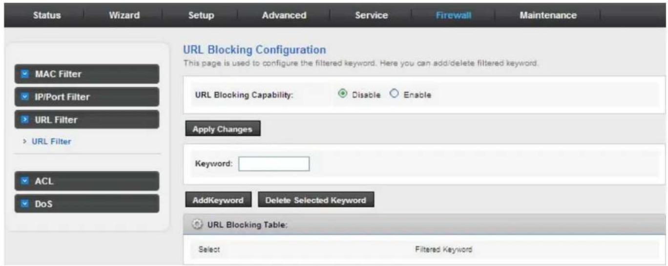
The following table describes the parameters and buttons on this page:
| Field Description | |
| URL Blocking Capability | You can choose Disable or Enable.● Select Disable to disable URL/KEYWORD blocking function and keyword filtering function.● Select Enable to block access to the URLs and keywords specified in the URL Blocking Table. |
| Keyword Enter the keyword to block. | |
| Add Keyword | Click it to add a URL/keyword to the URL Blocking Table. |
| Delete selected keyword | Select a row in the URL Blocking Table and click it to delete the row. |
| URL Blocking Table A list of the URL (s) to which access is blocked. | |
3.7.4 ACL
3.7.4.1 ACL
Choose Service > ACL, the page shown in the following figure appears. In this page, you can permit the data packets from LAN or WAN to access the router. You can configure the IP address for Access Control List (ACL). If ACL is enabled, only the effective IP address in the ACL can access the router.

If you select Enable in ACL capability, ensure that your host IP address is in ACL list before it takes effect.
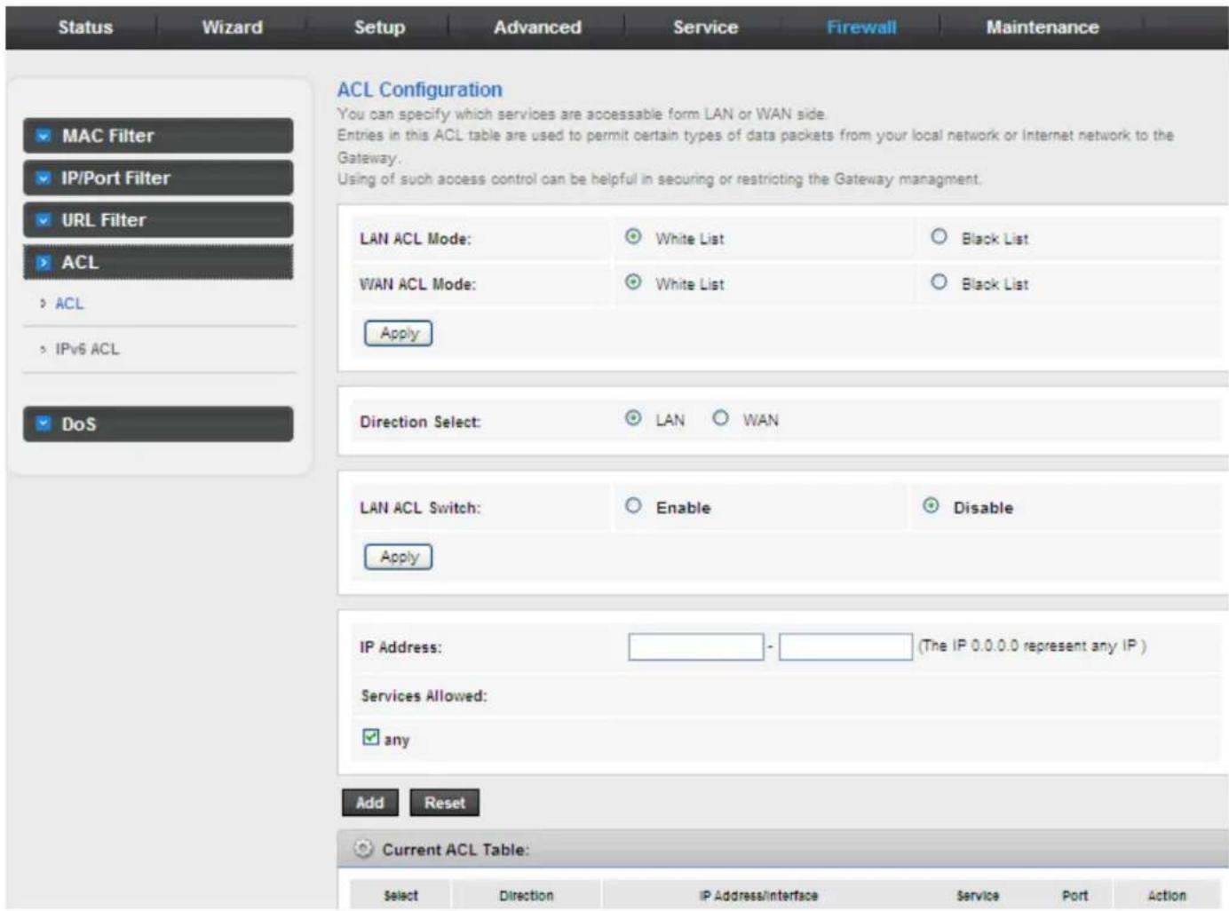
The following table describes the parameters and buttons of this page:
| Field Description | |
| Direction Select | Select the router interface. You can select LAN or WAN. In this example, LAN is selected. |
| LAN ACL Switch Select it to enable or disable ACL function. | |
| IP Address | Enter the IP address of the specified interface. Only the IP address that is in the same network segment with the IP address of the specified interface can access the router. |
| Services Allowed | You can choose the following services from LAN: Web, Telnet, SSH, FTP, TFTP, SNMP, or PING. You can also choose all the services. |
| Add | After setting the parameters, click it to add an entry to the Current ACL Table. |
| Reset Click it to refresh this page. | |
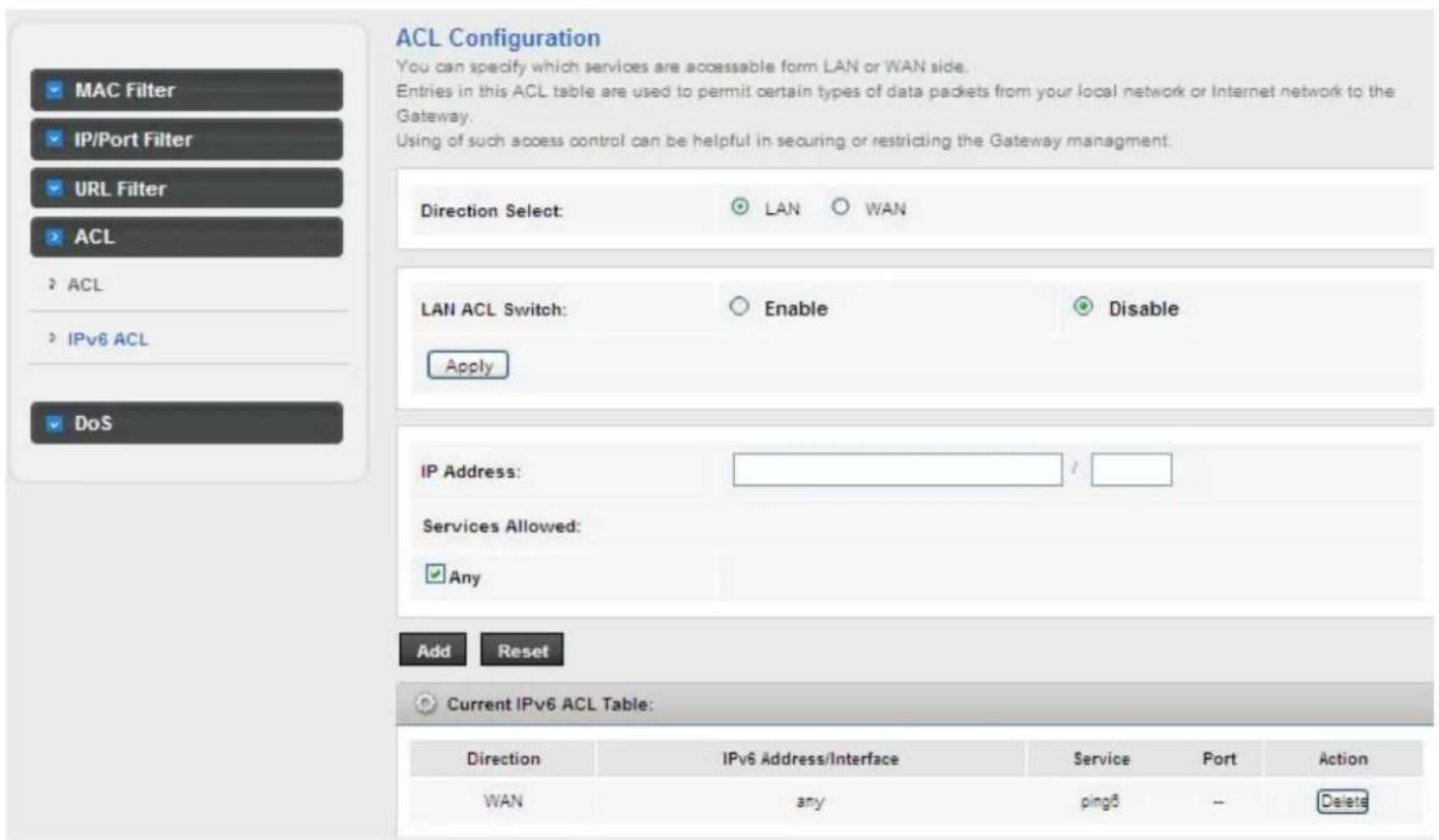
3.7.4.2 IPv6 ACL
3.7.5 DoS
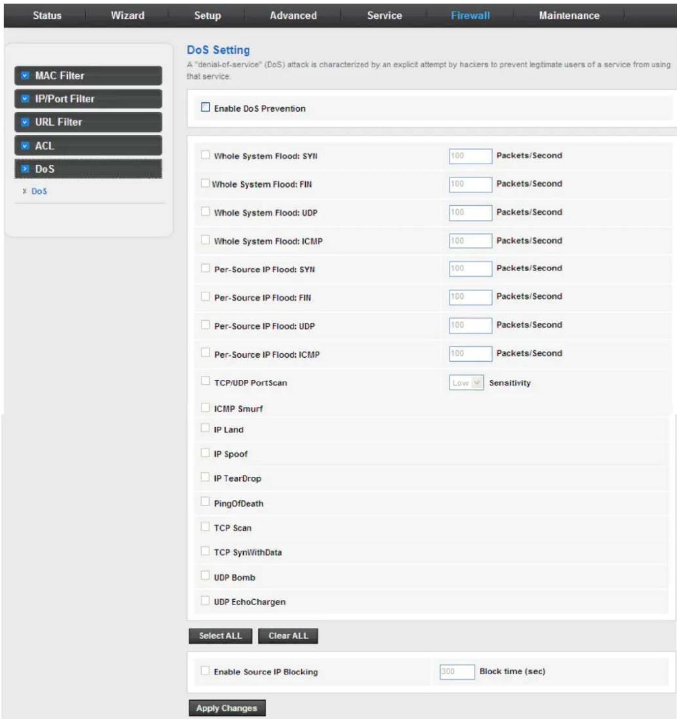
Denial-of-Service Attack (DoS attack) is a type of attack on a network that is designed to bring the network to its knees by flooding it with useless traffic.
Click Anti-DoS in the left pane and the page shown in the following figure appears. On this page, you can prevent DoS attacks.
3.8 Maintenance
In the navigation bar, click Maintenance. The Maintenance page displayed contains Update, Password, Reboot, Time Log and Diagnostics.
3.8.1 Update
Choose Maintenance > Update. The Update page displayed contains Upgrade Firmware and Backup/Restore.

Caution:
Do not turn off the router or press the Reset button while the procedure is in progress.
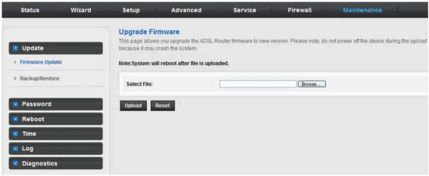
3.8.1.1 Upgrade Firmware
Click Upgrade Firmware in the left pane and the page shown in the following figure appears. On this page, you can upgrade the firmware of the router.
The following table describes the parameters and button on this page:
| Field Description | |
| Select File | ClickBrowse to select the firmware file. |
| Upload | After selecting the firmware file, clickUploadto starting upgrading the firmware file. |
| Reset Click it to starting selecting the firmware file. | |
3.8.1.2 Backup/Restore
Click Backup/Restore in the left pane and the page shown in the following figure appears. You can back up the current settings to a file and restore the settings from the file that was saved previously.
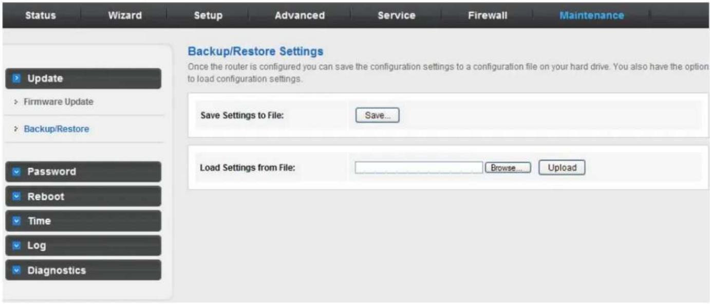
The following table describes the parameters and button of this page:
| Field Description | |
| Save Settings to File | Click it, and select the path. Then you can save the configuration file of the router. |
| Load Settings from File | Click Browse to select the configuration file. |
| Upload | After selecting the configuration file of the router, click Upload to start uploading the configuration file of the router. |
3.8.2 Password
Choose Maintenance > Password and the page shown in the following figure appears. By default, the user name and password of the administrator are admin and admin respectively. The user name and password of the common user are user and user respectively.
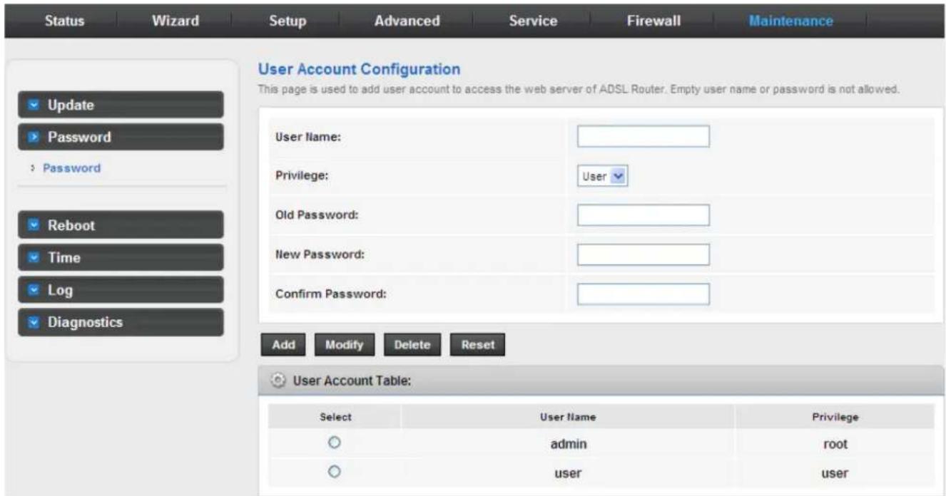
The following table describes the parameters of this page:
| Field Description | |
| User Name | Choose the user name for accessing the router. You can chooseadminor user. |
| Privilege Choose the privilege for the account. | |
| Old Password Enter the old password | |
3.8.3 Reboot
Choose Maintenance > Reboot and the page shown in the following figure appears. You can set the router reset to the default settings or set the router to commit the current settings.
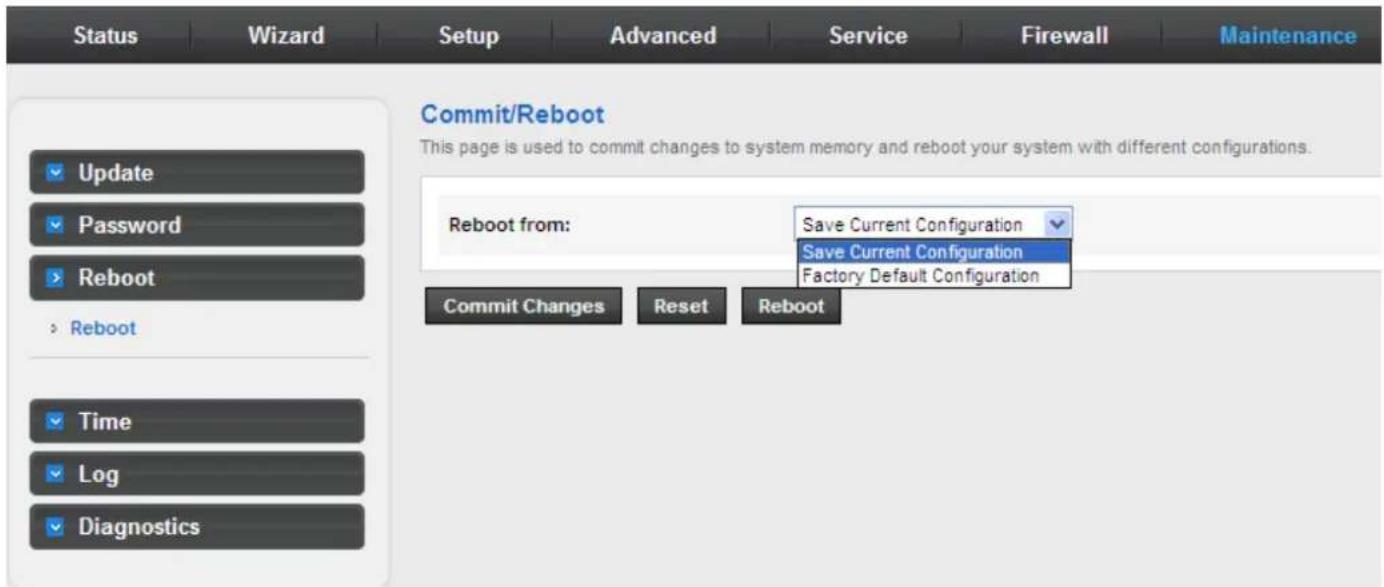
The following table describes the parameters and button on this page:
| Field Description | |
| Reboot from | You can choose Save current configuration or Factory default configuration.● Save current configuration: Save the current settings, and then reboot the router.● Factory default configuration: Reset to the factory default settings and then reboot the router. |
| Commit Changes Perform this action | |
| Reboot Click it to reboot the router. | |
3.8.4. Time
Choose Maintenance > Time and the page shown in the following figure appears. You can configure the system time manually or get the system time from the time server.
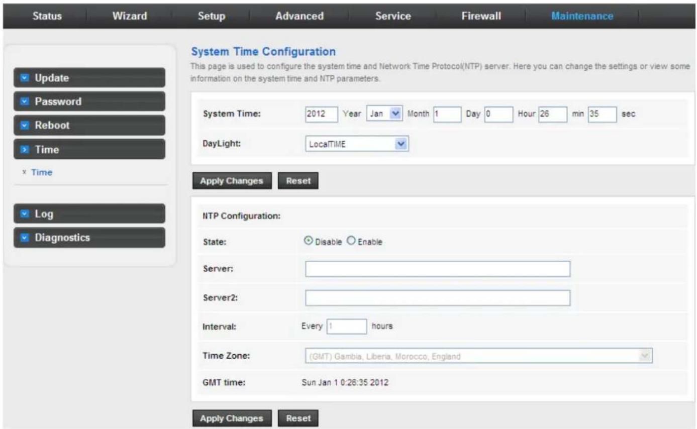
The following table describes the parameters of this page:
| Field Description | |
| System Time Set the system time manually. | |
| NTP Configuration | |
| State | Select enable or disable NTP function. You need to enable NTP if you want to configure the parameters of NTP. |
| Server Set the primary NTP server manually. | |
| Server 2 Set the secondary NTP server manually. | |
| Time Zone Choose the time zone in which area you are from the drop down list. | |
3.8.5 Log
Choose Admin > Log and the page shown in the following figure appears. In this page, you can enable or disable system log function and view the system log.
3.8.6 Diagnostic
In the navigation bar, click Diagnostic. The Diagnostic page displayed contains Ping, Ping6, Traceroute, Traceroute6, OAM Loopback, ADSL Statistics and Diag-Test.
3.8.6.1 Ping
Choose Diagnostic > Ping and the page shown in the following figure appears.
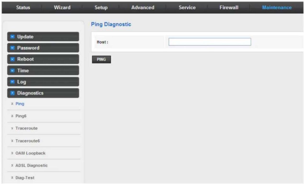
The following table describes the parameter and button on this page:
| Field Description | |
| Host Enter the valid IP address or domain name. | |
| Ping Click it to start to Ping. | |
3.8.6.2 Ping6
Choose Diagnostic > Ping6 and the page shown in the following figure appears.
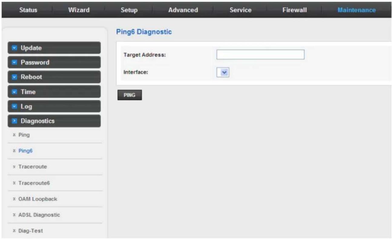
3.8.6.3 Traceroute
Choose Diagnostic >Traceroute and the following page appears. By Traceroute Diagnostic, you can track the route path through the information which is from your computer to the Internet other side host.
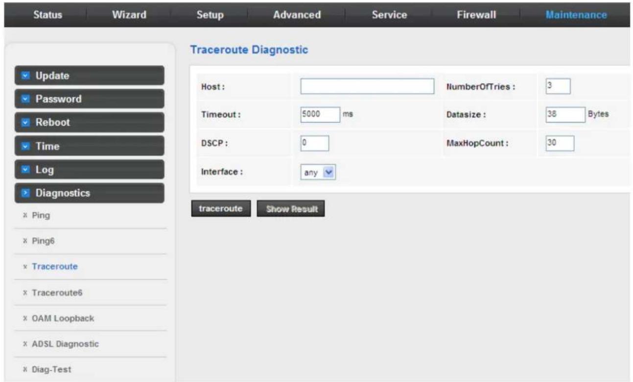
The following table describes the parameters and buttons on this page.
| Field Description | |
| Host Enter the destination host address for diagnosis. | |
| NumberOfTries Number of repetitions. | |
| Timeout Put in the timeout value. | |
| Datasize | Packet size. |
| DSCP Differentiated Services Code Point, You should set a value between 0-63. | |
| MaxHopCount Maximum number of routes. | |
| Interface Select the interface. | |
| Traceroute Click start traceroute. | |
3.8.6.4 Traceroute6
Choose Diagnostic >Traceroute6 and the following page appears. By Traceroute Diagnostic, you can track the route path through the information which is from your computer to the Internet other side host.
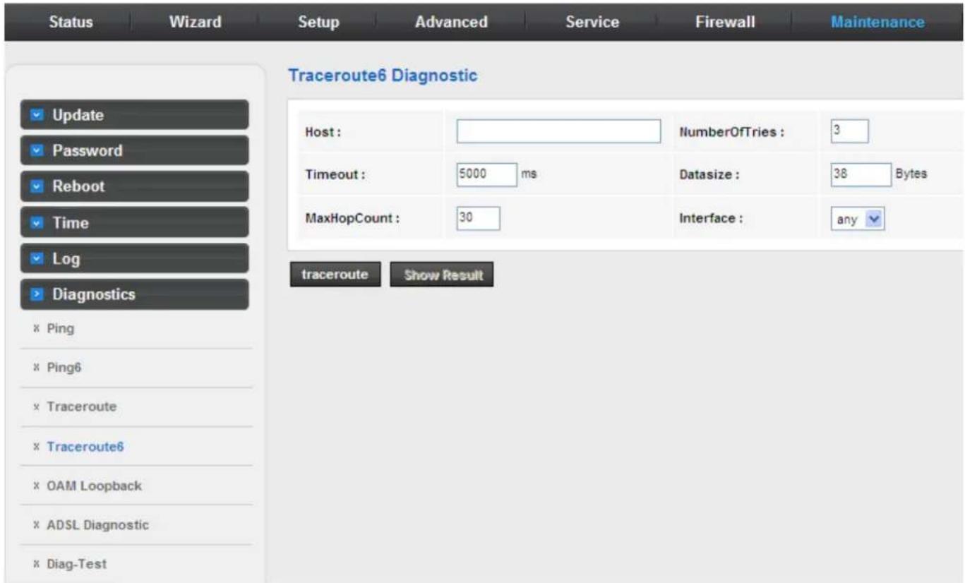
3.8.6.5 OAM Loopback
Choose Diagnostic > OAM Loopback and the page shown in the following figure appears. On this page, you can use VCC loopback function to check the connectivity of the VCC. The ATM loopback test is useful for troubleshooting problems with the DSLAM and ATM network.
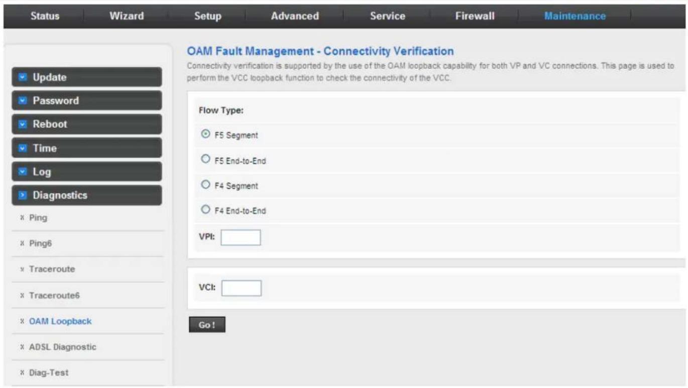
Click Go! to start testing.
3.8.6.6 ADSL Diagnostic
Choose Diagnostic > ADSL Diagnostic and the page shown in the following figure appears. It is used for ADSL tone diagnostics.
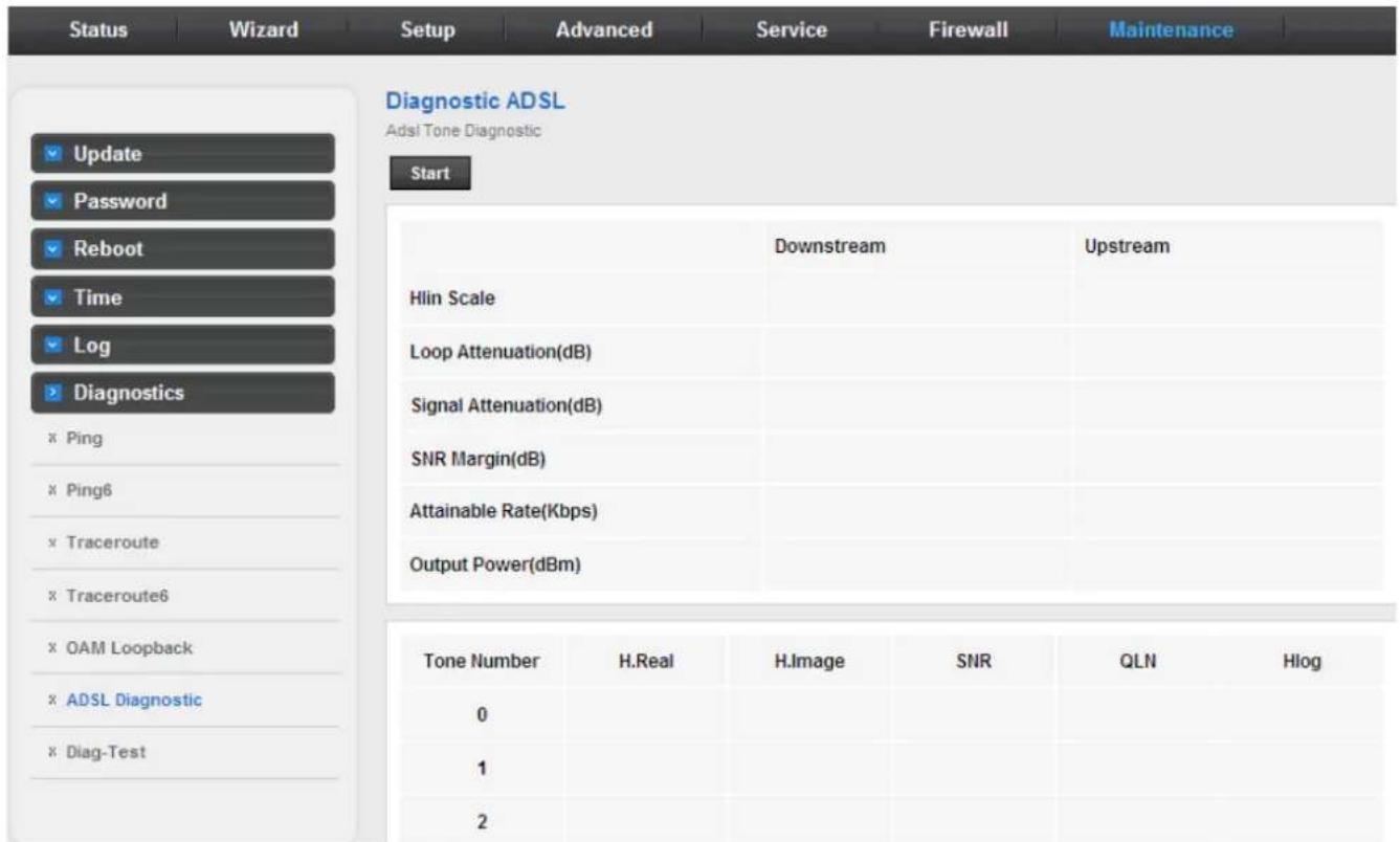
Click Start to start ADSL tone diagnostics.
3.8.6.7 Diag-Test
Choose Diagnostics > Diag-Test and the page shown in the following figure appears. On this page, you can test the DSL connection. You can also view the LAN status connection and ADSL connection.
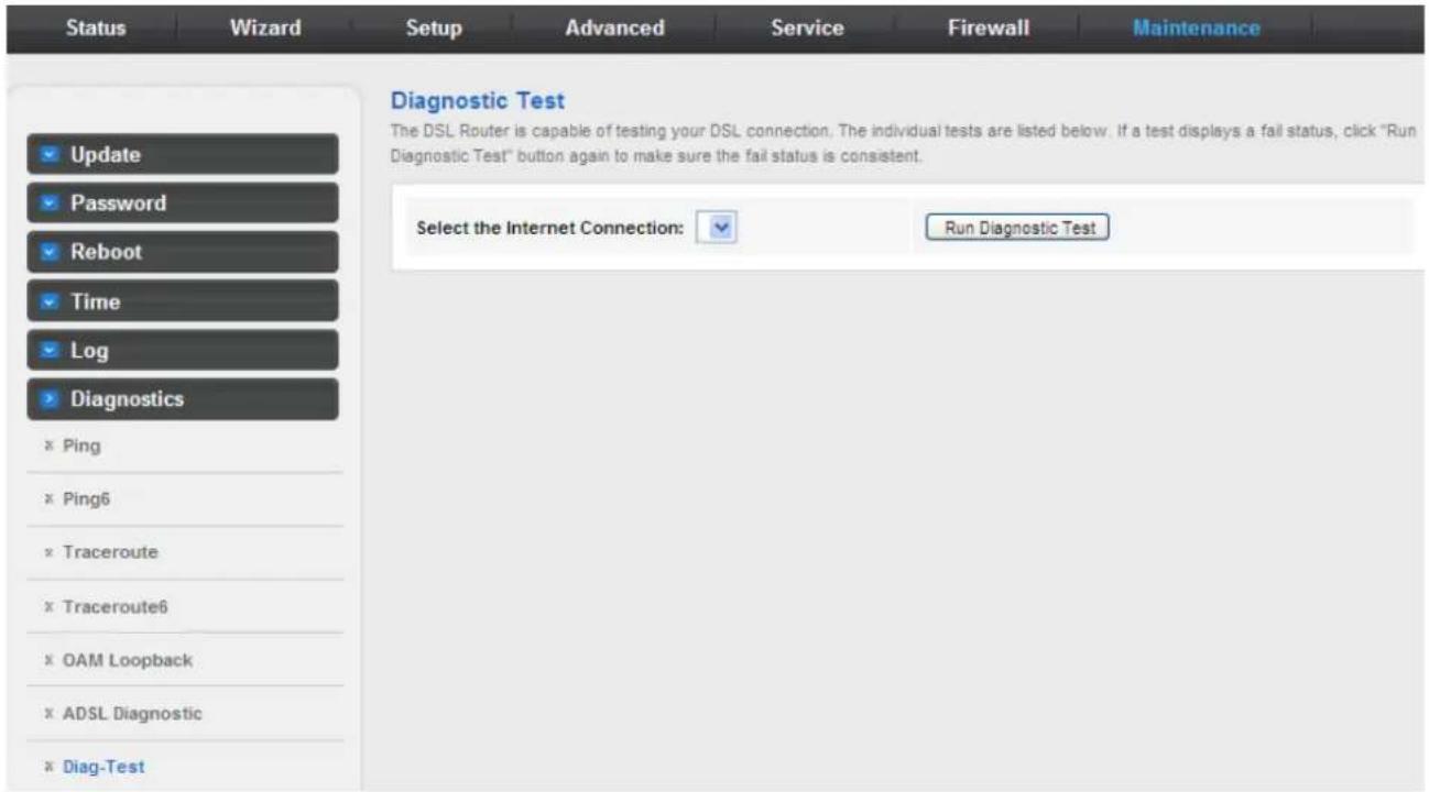
Click Run Diagnostic Test to start testing.
Chapter 4.Q&A
| Question Answer | |
| Why are all the indicators off? | Check the connection between the power adapter and the power socket.Check whether the power switch is turned on. |
| Why is the LAN indicator not on? | Check the following:The connection between the device and the PC, the hub, or the switchThe running status of the computer, hub, or switchThe cables connecting the device and other devices. Use a cross-over cable to connect the device to a computer. Use a straight-through cable to connect the device to a hub or a switch, |
| Why is the Link indicator not on? | Check the connection between the Line interface of the device and the socket. |
| Why does the Internet access fail when the Link indicator is on? | Ensure that the following information is entered correctly.VPI and VCIUser name and password |
| Why does the web configuration page of the device fail to be accessed? | Choose Start > Run from the desktop. Enter Ping 192.168.1.1 (the default IP address of the device) in the DOS window.If the web configuration page still cannot be accessed, check the following configurations.The type of network cableThe connection between the device and the computerThe TCP/IP properties of the network card of the computer |
| How to restore the default configuration after incorrect configuration? | Keep the device powered on and press the Reset button for 3 seconds, then the device automatically reboots and is restored to the factory default configuration.The default configurations of the device are as follows:IP address: 192.168.1.1Subnet mask: 255.255.255.0.For a super user, use admin for both user name and password. |
- Federal Communication Commission Interference Statement
- FCC Caution
- Federal Communication Commission (FCC) Radiation Exposure Statement
- Safety
- CE Mark Warning
- WEEE Regulation
- Revision
- Contents
- Chapter 1. Overview ......3
- Chapter 2. Hardware Installation 11
- Chapter 3. Web Configuration ……12
- Improved Networking Function for Future IP Compatibility
- Powerful Firewall and Complete Access Control Functions
- Application
- Wired Internet Connection
- Front Panel
- Rear Panel
- System Requirements
- Features
- Internet Access Features
- Advanced Internet Functions
- - RIP Routing
- - Simple Network Management Protocol (SNMP)
- LAN Features
- - DHCP Server Support
- Chapter 2. Hardware Installation
- Chapter 3. Web Configuration
- Accessing the Router
- Status
- Device Information
- ADSL
- Statistics
- Wizard
- Bridge
- PPPoE/PPPoA
- MER/1483 Routed
- Bridged
- Setup
- WAN
- WAN
- Auto PVC
- ATM
- ADSL
- LAN
- LAN
- DHCP
- Active DHCP Client Table
- DHCP Static IP
- LAN IPv6
- Advanced
- Routing
- Static Route
- IP Route Table
- IPv6 Static Route
- RIP
- NAT
- DMZ
- Virtual Server 3.5.2.2 Virtual Server
- ALG
- NAT Exclude IP
- Port Trigger
- FTP ALG Port
- NAT IP Mapping
- QoS
- TR-069
- 3.5.5.Others
- Bridge Setting
- Client Limit
- Tunnel
- Others
- Service
- IGMP
- IGMP Proxy
- MLD
- UPNP
- SNMP
- DNS
- DNS
- IPv6 DNS
- DDNS
- Firewall
- MAC Filter
- IP/Port Filter
- IP/Port Filter
- IPV6/Port Filter
- URL Filter
- ACL
- ACL
- IPv6 ACL
- DoS
- Maintenance
- Update
- Upgrade Firmware
- Backup/Restore
- Password
- Reboot
- Time
- Log
- Diagnostic
- Ping
- Ping6
- Traceroute
- Traceroute6
- OAM Loopback
- ADSL Diagnostic
- Diag-Test
Brand : Planet
Model : ADE-3400A
Category : Router