WNRT-617 - Router Planet - Free user manual and instructions
Find the device manual for free WNRT-617 Planet in PDF.


| Product Type | 150Mbps 802.11n Wireless Broadband Router |
| Brand | Planet |
| Model | WNRT-617 |
| Wireless Standard | IEEE 802.11b/g/n |
| Maximum Data Rate | Up to 150 Mbps (802.11n) |
| Frequency Band | 2.4 GHz |
| Antenna | 1 x Fixed 5 dBi Omni-directional |
| WAN Port | 1 x 10/100 Mbps Auto MDI/MDI-X RJ45 |
| LAN Ports | 4 x 10/100 Mbps Auto MDI/MDI-X RJ45 |
| Firewall | NAT with SPI, DoS protection |
| Wireless Security | WEP 64/128/152-bit, WPA/WPA2-PSK, WPA/WPA2 Enterprise, WPS |
| Operation Modes | Router, Client, Repeater, Bridge with AP, Multi-SSID |
| DHCP Server | Built-in |
| VPN Pass-through | PPTP, L2TP, IPSec |
| Management | Web-based (HTTP), Remote Management |
| LED Indicators | PWR, SYS, WLAN, LAN1-4, WAN, WPS |
| Material | Plastic |
| Compliance | FCC, CE, R&TTE, WEEE |
| Package Contents | Router, Power Adapter, Ethernet Cable, Quick Installation Guide, CD-ROM |
| Safety | Do not open device. Avoid exposure to water. Keep away from heat sources. |
| Maintenance | Keep vents clear. Wipe with a dry cloth. Do not use liquid cleaners. |
| Repairability | No user-serviceable parts inside. Contact qualified service personnel for repairs. |
Frequently Asked Questions - WNRT-617 Planet
User questions about WNRT-617 Planet
0 question about this device. Answer the ones you know or ask your own.
Ask a new question about this device
Download the instructions for your Router in PDF format for free! Find your manual WNRT-617 - Planet and take your electronic device back in hand. On this page are published all the documents necessary for the use of your device. WNRT-617 by Planet.
USER MANUAL WNRT-617 Planet
natural_image
Woman in business attire using a laptop on stairs (no visible text or symbols)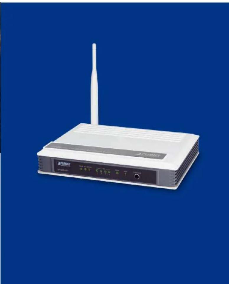
natural_image
White PUENET wireless router on a blue background, no visible text or symbols on the device bodyCopyright
Copyright © 2013 by PLANET Technology Corp. All rights reserved. No part of this publication may be reproduced, transmitted, transcribed, stored in a retrieval system, or translated into any language or computer language, in any form or by any means, electronic, mechanical, magnetic, optical, chemical, manual or otherwise, without the prior written permission of PLANET.
PLANET makes no representations or warranties, either expressed or implied, with respect to the contents hereof and specifically disclaims any warranties, merchantability or fitness for any particular purpose. Any software described in this manual is sold or licensed "as is". Should the programs prove defective following their purchase, the buyer (and not this company, its distributor, or its dealer) assumes the entire cost of all necessary servicing, repair, and any incidental or consequential damages resulting from any defect in the software. Further, this company reserves the right to revise this publication and to make changes from time to time in the contents hereof without obligation to notify any person of such revision or changes.
All brand and product names mentioned in this manual are trademarks and/or registered trademarks of their respective holders.
Federal Communication Commission Interference Statement
This equipment has been tested and found to comply with the limits for a Class B digital device, pursuant to

Part 15 of FCC Rules. These limits are designed to provide reasonable protection against harmful interference in a residential installation. This equipment generates, uses, and can radiate radio frequency energy and, if not installed and used in accordance with the instructions, may cause
harmful interference to radio communications. However, there is no guarantee that interference will not occur in a particular installation. If this equipment does cause harmful interference to radio or television reception, which can be determined by turning the equipment off and on, the user is encouraged to try to correct the interference by one or more of the following measures:
- Reorient or relocate the receiving antenna.
- Increase the separation between the equipment and receiver.
- Connect the equipment into an outlet on a circuit different from that to which the receiver is connected.
- Consult the dealer or an experienced radio technician for help.
FCC Caution:
To assure continued compliance, (example-use only shielded interface cables when connecting to computer or peripheral devices) any changes or modifications not expressly approved by the party responsible for compliance could void the user's authority to operate the equipment.
This device complies with Part 15 of the FCC Rules. Operation is subject to the Following two conditions:
(1) This device may not cause harmful interference
(2) This Device must accept any interference received, including interference that may cause undesired operation.
Any changes or modifications not expressly approved by the party responsible for compliance could void the user's authority to operate the equipment.
Federal Communication Commission (FCC) Radiation Exposure Statement
This equipment complies with FCC radiation exposure set forth for an uncontrolled environment. In order to avoid the possibility of exceeding the FCC radio frequency exposure limits, human proximity to the antenna shall not be less than 20 cm (8 inches) during normal operation.
R&TTE Compliance Statement
This equipment complies with all the requirements of DIRECTIVE 1999/5/CE OF THE EUROPEAN PARLIAMENT AND THE COUNCIL OF 9 March 1999 on radio equipment and telecommunication terminal Equipment and the mutual recognition of their conformity (R&TTE).
The R&TTE Directive repeals and replaces in the directive 98/13/EEC (Telecommunications Terminal Equipment and Satellite Earth Station Equipment) As of April 8, 2000.
Safety
This equipment is designed with the utmost care for the safety of those who install and use it. However, special attention must be paid to the dangers of electric shock and static electricity when working with electrical equipment. All guidelines of this and of the computer manufacture must therefore be allowed at all times to ensure the safe use of the equipment.
National Restrictions
This device is intended for home and office use in all EU countries (and other countries following the EU directive 1999/5/EC) without any limitation except for the countries mentioned below:
| Country | Restriction | Reason/remark |
| Bulgaria | None | General authorization required for outdoor use and public service |
| France | Outdoor use limited to 10 mW e.i.r.p. within the band 2454-2483.5 MHz | Military Radiolocation use. Refarming of the 2.4 GHz band has been ongoing in recent years to allow current relaxed regulation. Full implementation planned 2012 |
| Italy | None | If used outside of own premises, general authorization is required |
| Luxembourg | None | General authorization required for network and service supply(not for spectrum) |
| Norway | Implemented | This subsection does not apply for the geographical area within a radius of 20 km from the centre of Ny-Ålesund |
| Russian Federation | None Only for indoor applications | |
Note: Please don't use the product outdoors in France
WEEE regulation

To avoid the potential effects on the environment and human health as a result of the presence of hazardous substances in electrical and electronic equipment, end users of electrical and electronic equipment should understand the meaning of the crossed-out wheeled bin symbol. Do not dispose of WEEE as unsorted municipal waste; they have to be collected separately.
Revision
User's Manual for PLANET 802.11n Wireless Broadband Router
Model: WNRT-617
Rev: 2.0 (MAY. 2013)
Part No: EM-WNRT-617v2_v2.0 (2081-E50200-002)
CONTENTS
Chapter 1. Product Introduction......12
1.1 Package Contents....12
1.2 Product Description....12
1.3 Product Features....13
1.4 Product Specifications....14
Chapter 2. Hardware Installation ...... 17
2.1 Hardware Description.... 17
2.1.1 The Front Panel....17
2.1.2 LED Indications....17
2.1.3 The Rear Panel....19
Chapter 3. Connecting the Router....20
3.1 System Requirements....20
3.2 Installing the Router 20
Chapter 4. Quick Installation Guide ......22
4.1 Manual Network Setup - TCP/IP Configuration 22
4.1.1 Obtain an IP Address Automatically....22
4.1.2 Configure the IP Address Manually 25
4.2 Starting Setup in Web UI....29
4.3 PLANET Smart Setup! Utility 36
Chapter 5. Configuring the Router....38
5.1 Login....38
5.2 Status 38
5.3 Quick Setup....39
5.4 Operation Mode 40
5.5 WPS 42
5.6 Network....46
5.6.1 WAN....46
5.6.2 LAN....57
5.6.3 MAC Clone 59
5.7 Wireless....60
5.7.1 Wireless Settings....60
5.7.2 Wireless Security 63
5.7.3 Wireless MAC Filtering 68
5.7.4 Wireless Advanced 71
5.7.5 Wireless Statistics....73
5.8 DHCP 74
5.8.1 DHCP Settings....74
5.8.2 DHCP Clients List 75
5.8.3 Address Reservation 76
5.9 NAT 78
5.10 Forwarding 79
5.10.1 Virtual Servers 79
5.10.2 Port Triggering 82
5.10.3 DMZ 84
5.10.4 UPnP 85
5.11 Security 86
5.11.1 Basic Security 86
5.11.2 Advanced Security....88
5.11.3 Local Management....90
5.11.4 Remote Management 92
5.12 Parental Control 93
5.13 Access Control....97
5.13.1 Rule....97
5.13.2 Host....101
5.13.3 Target....103
5.13.4 Schedule....106
5.14 Advanced Routing....108
5.14.1 Static Routing List.... 108
5.14.2 System Routing Table.... 110
5.15 Bandwidth Control.... 111
5.15.1 Control Settings 111
5.15.2 Rules List.... 112
5.16 IP & MAC Binding 113
5.16.1 Binding Settings.... 113
5.16.2 ARP List.... 116
5.17 Dynamic DNS....118
5.17.1 Comexe.cn DDNS 118
5.17.2 Dyndns.org DDNS 119
5.17.3 No-ip.com DDNS 120
5.17.4 Planetddns.com DDNS....121
5.18 System Tools....123
5.18.1 Time Settings....123
5.18.2 Diagnostic....125
5.18.3 Firmware Upgrade 127
5.18.4 Factory Defaults....128
5.18.5 Backup & Restore....129
5.18.6 Reboot 129
5.18.7 Password....130
5.18.8 System Log....131
5.18.9 Statistics....134
Chapter 6. Quick Connection to a Wireless Network....136
6.1 Windows XP (Wireless Zero Configuration)....136
6.2 Windows 7 (WLAN AutoConfig)....138
6.3 Mac OS X 10.x....141
6.4 iPhone / iPod Touch / iPad 143
Appendix A: FAQ....146
Appendix B: Configuring the PCs 153
Appendix C: Specifications....157
Appendix D: Glossary....160
FIGURE
FIGURE 2-1 WNRT-617 FRONT PANEL....17
FIGURE 2-2 WNRT-617 FRONT PANEL....18
FIGURE 3-1 ADJUST THE DIRECTION OF THE ANTENNA 21
FIGURE 3-2 HARDWARE INSTALLATION OF THE WNRT-617 WIRELESS ROUTER....21
FIGURE 4-1 CHANGE ADAPTER SETTINGS....23
FIGURE 4-2 NETWORK CONNECTION PROPERTIES....23
FIGURE 4-3 TCP/IP SETTING....24
FIGURE 4-4 OBTAIN AN IP ADDRESS AUTOMATICALLY ....25
FIGURE 4-5 USE STATIC IP ADDRESS....26
FIGURE 4-6 WINDOWS 7 - SEARCH BOX....27
FIGURE 4-7 SUCCESSFUL RESULT OF PING COMMAND....27
FIGURE 4-8 FAILED RESULT OF PING COMMAND 28
FIGURE 4-9 LOGIN THE ROUTER....29
FIGURE 4-10 LOGIN WINDOW ......29
FIGURE 4-11 WNRT-617 WEB UI SCREENSHOT 30
FIGURE 4-12 QUICK SETUP ....30
FIGURE 4-13 QUICK SETUP – WAN CONNECTION TYPE....31
FIGURE 4-14 QUICK SETUP – PPPoE....31
FIGURE 4-15 QUICK SETUP - STATIC IP 32
FIGURE 4-16 QUICK SETUP – MAC CLONE ....32
FIGURE 4-17 QUICK SETUP – WIRELESS....33
FIGURE 4-18 QUICK SETUP – FINISH (NO WIRELESS PARAMETER CHANGED)....35
FIGURE 4-19 QUICK SETUP – FINISH (REBOOT IS REQUIRED) ......35
FIGURE 4-20 LAN PORT CONNECTION OF THE WNRT-617 WIRELESS ROUTER 36
FIGURE 4-21 INSERT THE CD TO THE LAPTOP ......36
FIGURE 4-22 PLANET SMART SETUP! PROGRAM SCREENSHOT....37
FIGURE 5-1 MAIN MENU ....38
FIGURE 5-2 ROUTER STATUS....39
FIGURE 5-3 OPERATION MODE....40
FIGURE 5-4 WPS....42
FIGURE 5-5 HARDWARE WPS/RESET BUTTON 43
FIGURE 5-6 SOFTWARE WPS/RESET BUTTON....43
FIGURE 5-7 ADD A NEW DEVICE....44
FIGURE 5-8 NEW DEVICE CONNECTED SUCCESSFULLY 45
FIGURE 5-9 THE NETWORK MENU 46
FIGURE 5-10 WAN - DYNAMIC IP 47
FIGURE 5-11 WAN - STATIC IP....48
FIGURE 5-12 WAN – PPPoE 49
FIGURE 5-13 PPPoE ADVANCED SETTINGS ....51
FIGURE 5-14 WAN – BIGPOND CABLE....52
FIGURE 5-15 WAN - L2TP SETTINGS....54
FIGURE 5-16 WAN - PPTP SETTINGS....56
FIGURE 5-17 LAN SETTINGS ....58
FIGURE 5-18 MAC ADDRESS CLONE....59
FIGURE 5-19 WIRELESS MENU....60
FIGURE 5-20 WIRELESS SETTINGS....60
FIGURE 5-21 WDS SETTINGS....62
FIGURE 5-22 WIRELESS SECURITY - NONE....64
FIGURE 5-23 WIRELESS SECURITY - WEP 64
FIGURE 5-24 WIRELESS SECURITY - WPA/WPA2 ENTERPRISE 66
FIGURE 5-25 WIRELESS SECURITY - WPA/WPA2 PERSONAL....67
FIGURE 5-26 WIRELESS MAC ADDRESS FILTERING 68
FIGURE 5-27 ADD OR MODIFY WIRELESS MAC ADDRESS FILTERING ENTRY 69
FIGURE 5-28 WIRELESS MAC ADDRESS FILTERING 70
FIGURE 5-29 WIRELESS ADVANCED 71
FIGURE 5-30 THE ROUTER ATTACHED WIRELESS STATIONS....73
FIGURE 5-31 THE DHCP MENU....74
FIGURE 5-32 DHCP SETTINGS....74
FIGURE 5-33 DHCP CLIENTS LIST 76
FIGURE 5-34 ADDRESS RESERVATION....77
FIGURE 5-35 ADD OR MODIFY AN ADDRESS RESERVATION ENTRY .....77
FIGURE 5-36 NAT FUNCTION....78
FIGURE 5-37 THE FORWARDING MENU 79
FIGURE 5-38 VIRTUAL SERVERS 79
FIGURE 5-39 ADD OR MODIFY A VIRTUAL SERVER ENTRY....80
FIGURE 5-40 PORT TRIGGERING 82
FIGURE 5-41 ADD OR MODIFY A TRIGGERING ENTRY....83
FIGURE 5-42 DMZ 84
FIGURE 5-43 UPNP SETTING....85
FIGURE 5-44 THE SECURITY MENU....86
FIGURE 5-45 BASIC SECURITY....87
FIGURE 5-46 ADVANCED SECURITY....89
FIGURE 5-52 ACCESS CONTROL....97
FIGURE 5-53 ACCESS CONTROL RULE MANAGEMENT....97
FIGURE 5-54 ADD OR MODIFY INTERNET ACCESS CONTROL ENTRY....99
FIGURE 5-55 ACCESS CONTROL RULE LIST 100
FIGURE 5-56 ACCESS CONTROL HOST SETTINGS....101
FIGURE 5-57 ADD OR MODIFY A HOST ENTRY – IP MODE....102
FIGURE 5-58 ADD OR MODIFY A HOST ENTRY – MAC ADDRESS MODE 102
FIGURE 5-59 HOST SETTINGS LIST 103
FIGURE 5-60 TARGET SETTINGS ....103
FIGURE 5-61 ADD OR MODIFY AN ACCESS TARGET ENTRY ....104
FIGURE 5-62 ADD OR MODIFY AN ACCESS TARGET ENTRY 105
FIGURE 5-63 TARGET SETTINGS LIST....106
FIGURE 5-64 SCHEDULE SETTINGS....106
FIGURE 5-65 ADVANCED SCHEDULE SETTINGS....107
FIGURE 5-66 SCHEDULE SETTINGS LIST....108
FIGURE 5-67 ADVANCED ROUTING....108
FIGURE 5-68 STATIC ROUTING....109
FIGURE 5-69 ADD OR MODIFY A STATIC ROUTE ENTRY....109
FIGURE 5-70 SYSTEM ROUTING TABLE....110
FIGURE 5-71 BANDWIDTH CONTROL.... 111
FIGURE 5-72 BANDWIDTH CONTROL SETTINGS....111
FIGURE 5-73 BANDWIDTH CONTROL RULES LIST 112
FIGURE 5-74 BANDWIDTH CONTROL RULE SETTINGS....113
FIGURE 5-75 THE IP & MAC BINDING MENU 113
FIGURE 5-76 BINDING SETTING....114
FIGURE 5-77 IP & MAC BINDING SETTING (ADD & MODIFY)....115
FIGURE 5-78 FIND IP & MAC BINDING ENTRY 116
FIGURE 5-79 ARP LIST 116
FIGURE 5-80 COMEXE.CN DDNS SETTINGS....118
FIGURE 5-81 DYNDNS.ORG DDNS SETTINGS....119
FIGURE 5-82 No-IP.COM DDNS SETTINGS....120
FIGURE 5-83 WAN SETTINGS....121
FIGURE 5-84 PLANETDDNS.COM DDNS SETTINGS 122
FIGURE 5-85 MY DEVICES....122
FIGURE 5-86 THE SYSTEM TOOLS MENU 123
FIGURE 5-87 TIME SETTINGS 123
FIGURE 5-88 DIAGNOSTIC TOOLS....125
FIGURE 5-89 DIAGNOSTIC RESULTS....126
FIGURE 5-90 FIRMWARE UPGRADE 127
FIGURE 5-91 RESTORE FACTORY DEFAULT....128
FIGURE 5-92 BACKUP & RESTORE CONFIGURATION....129
FIGURE 5-93 REBOOT THE ROUTER 129
FIGURE 5-94 PASSWORD....130
FIGURE 5-95 SYSTEM LOG 131
FIGURE 5-96 MAIL ACCOUNT SETTINGS....132
FIGURE 5-97 MAIL ACCOUNT SETTINGS - AUTHENTICATION .... 133
FIGURE 5-98 STATISTICS 134
FIGURE 6-1 WIRELESS ZERO CONFIGURATION....136
FIGURE 6-2 CHOOSE A WIRELESS NETWORK ....136
FIGURE 6-3 ENTER THE ENCRYPTION KEY....137
FIGURE 6-4 WIRELESS NETWORK CONNECTED....137
FIGURE 6-5 WLAN AUTOCONFIG....138
FIGURE 6-6 WLAN AUTOCONFIG WINDOW 138
FIGURE 6-7 WLAN AUTOCONFIG – TYPE THE NETWORK SECURITY KEY ...... 139
FIGURE 6-8 WLAN AUTOCONFIG - CONNECTING....139
FIGURE 6-9 WLAN AUTOCONFIG - CONNECTED 140
FIGURE 6-10 THE AIRPORT NETWORK CONNECTION ICON 141
FIGURE 6-11 THE AIRPORT NETWORK CONNECTION MENU 141
FIGURE 6-12 THE AIRPORT NETWORK CONNECTION – ENTER PASSWORD....142
FIGURE 6-13 THE AIRPORT NETWORK CONNECTION – CONNECTED....142
FIGURE 6-14 THE WI-FI SETTINGS IN IPHONE/IPOD TOUCH/IPAD....143
FIGURE 6-15 GENERAL SETTINGS....143
FIGURE 6-16 GENERAL SETTINGS – NOT CONNECTED .... 144
FIGURE 6-17 GENERAL SETTINGS – Wi-Fi ON 144
FIGURE 6-18 GENERAL SETTINGS – ENTER PASSWORD....145
FIGURE 6-19 GENERAL SETTINGS – WI-FI NETWORK CONNECTED....145
FIGURE A-1 PPPoE CONNECTION TYPE 146
FIGURE A-2 MAC CLONE 147
FIGURE A-3 VIRTUAL SERVERS....148
FIGURE A-4 ADD OR MODIFY A VIRTUAL SERVER ENTRY 148
FIGURE A-5 DMZ....149
FIGURE A-6 BASIC SECURITY 150
FIGURE A-7 REMOTE MANAGEMENT 151
FIGURE A-8 VIRTUAL SERVERS....151
FIGURE A-9 ADD OR MODIFY A VIRTUAL SERVER ENTRY 152
FIGURE B-1 NETWORK CONNECTION PROPERTIES 153
FIGURE B-2 TCP/IP SETTINGS 154
FIGURE B-3 TCP/IP – OBTAIN AN IP ADDRESS AUTOMATICALLY 155
FIGURE B-4 TCP/IP SETTINGS – STATIC IP 156
Chapter 1. Product Introduction
1.1 Package Contents
The following items should be contained in the package:
WNRT-617 Wireless Broadband Router
Power Adapter
- Ethernet Cable
Quick Installation Guide
- CD-ROM (User's Manual included)
If there is any item missing or damaged, please contact the seller immediately.
1.2 Product Description
The WNRT-617 is integrated with a 4-port Switch, Firewall, NAT-Router and Wireless AP. The 150Mbps Wireless Broadband Router delivers an exceptional range and speed, which can fully meet the need of Small Office/Home Office (SOHO) networks and the users demanding higher networking performance.
Easy Installation
The WNRT-617 provides a total solution for the home and the SOHO users. With the MIMO 11n wireless technology, it's easy to combine the wireless devices with existing wired network.
Multiple Wireless Network Technologies for Greater Access
PLANET Wireless Broadband Router, WNRT-617, features 802.11n radio with 1T1R antenna technology compliant with 802.11b/g standards. Compared with general wireless routers, the WNRT-617 offers more powerful and flexible capability for LAN clients to access the Internet with management functions.
Incredibly High Speed
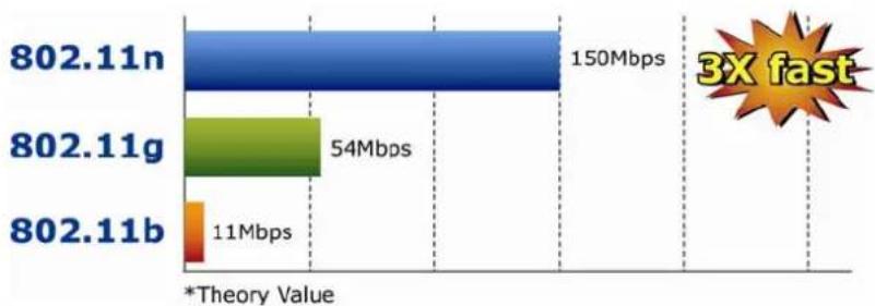
The WNRT-617 Wireless Broadband Router provides speed of up to 150Mbps which is 3x of the traditional 11g products, and the use of high bandwidth-consuming applications such as HD Videos.
bar
| Category | Value (Mbps) | |---|---| | 802.11n | 150 | | 802.11g | 54 | | 802.11b | 11 | *Theory Value; 3X fastWide Range of Wireless Security Support
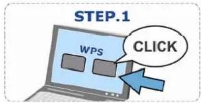
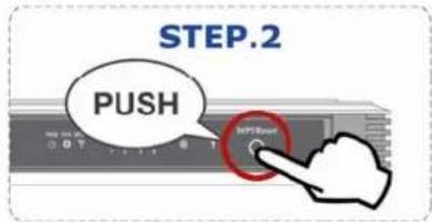
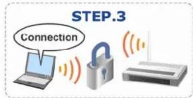
The WNRT-617 supports one WAN port for wired cable or DSL service connection. To secure the wireless communication, the WNRT-617 supports up-to-date encryption, WPA-PSK/WPA2-PSK with TKIP/AES. In order to simplify the security settings, the WNRT-617 supports Wi-Fi Protected Setup (WPS) configuration with PBC/PIN method. By just clicking the options, the secure connection between AP and wireless client will be built immediately.
WPS (Wi-Fi Protected Setup)
Quick & Easy Wireless connection
Advanced Firewall Security
The WNRT-617 supports NAT function to allow multiple users to access the Internet via a single legal IP. It also provides Virtual Server for LAN PC to act as an application server and offers certain service to the clients on Internet. Furthermore, the SPI (Stateful Packet Inspection) firewall protects your Intranet PCs from unauthorized accesses and many kinds of DoS attacks from the Internet. In the aspect of firewall, the WNRT-617 supplies IP-based and MAC-based access control, and prevents possible hackers attack.
1.3 Product Features
Industrial Compliant Wireless LAN & LAN
■ Compliant with IEEE 802.11n wireless technology capable of up to 150Mbps data rate
■ Backward compatible with 802.11b/g standard
■ Equipped with four LAN ports (10/100Mbps) and one WAN port (10/100Mbps), Auto MDI/MDI-X supported
xed-network Broadband Router
■ Supported connection types: Dynamic IP/ Static IP / PPPoE / Telstra Big Pond / L2TP / PPTP
■ Supports Static Routing, WDS, UPnP, Dynamic DNS
Secure Network Connection
■ Supports Wi-Fi Protected Setup (WPS)
■ Advanced security: 64/128/152-bit WEP, WPA/WPA2 and WPA-PSK/WPA2-PSK(TKIP/AES encryption), 802.1x
■ Supports NAT firewall features, with SPI function to protect against DoS attacks.
■ Supports IP / Protocol-based access control and MAC Filtering
Advanced Networking function for Specific Application
■ Supports multiple sessions IPSec, L2TP and PPTP VPN pass-through
■ Supports Virtual Server, ALG, DMZ and UPnP for various networking applications
■ Supports DHCP Server
> Easy Installation & Management
■ Web-based UI for and Quick setup for easy configuration
■ Remote Management allows configuration from a remote site
■ System status monitoring includes DHCP Client, System Log
1.4 Product Specifications
| Product | WNRT-617150Mbps 802.11n Wireless Broadband Router | |
| Hardware Specification | ||
| Interface | WAN Port: 1 x 10/100Mbps Auto MDI/MDI-X RJ45 port | |
| LAN Port: 4 x 10/100Mbps Auto MDI/MDI-X RJ45 ports | ||
| Antenna | Gain: 1 x Fixed 5dBi Antenna | |
| Orientation: Omni-directional | ||
| Power Button Power On/Off button at rear panel | ||
| WPS / Reset Button | WPS / Reset button at front panelPush for above 5 seconds to reset to factory default setting | |
| LED Indicators | PWR, SYS, WLAN, LAN x 4, WAN, WPS with green light | |
| Material Plastic | ||
| Wireless Interface Specification | ||
| Standard | Compliance with IEEE 802.11b/g/n | |
| Frequency Band | 2.4~2.4835GHz | |
| Extend Frequency | DSSS | |
| Modulation Type | DBPSK, DQPSK, QPSK, CCK and OFDM (BPSK/QPSK/16-QAM/ 64-QAM) | |
| Data Transmission Rates | 11n: 135/121.5/108/81/54/40.5/27/13.5Mbps130/117/104/78/52/39/26/13Mbps65/58.5/52/39/26/19.5/13/6.5Mbps (Dynamic)11g: 54/48/36/24/18/12/9/6Mbps (Dynamic)11b: 11/5.5/2/1Mbps (Dynamic) | |
| Transmission Distance | Indoor up to 100mOutdoor up to 300m (it is limited to the environment) | |
| Channel | America/ FCC: 2.414~2.462GHz (11 Channels)Europe/ ETSI: 2.412~2.472GHz (13 Channels)Japan/ TELEC: 2.412~2.484GHz (14 Channels) | |
| RF Power | High: 18 dBm (max)Middle: 15 dBmLow: 12 dBm | |
| Receive Sensitivity | 130M: -68dBm@10% PER108M: -68dBm@10% PER54M: -68dBm@10% PER11M: -85dBm@8% PER6M: -88dBm@10% PER1M: -90dBm@8% PER | |
| Wireless Management Features | ||
| Wireless Operation Mode | AP, WDS (AP+Bridge) | |
| Encryption Security | WEP (64/128/152-bit) encryption security | |
| WPA-PSK / WPA2-PSK (TKIP/AES)WPA / WPA2 (TKIP/AES)WPA / WPA2 enterprise mode (802.1x authentication) | ||
| Wireless Security | Provides wireless LAN ACL (Access Control List) filtering | |
| Wireless MAC address filtering | ||
| Supports WPS(WIFI Protected Setup ) | ||
| Enable/Disable SSID Broadcast | ||
| Wireless Advanced | Supports 802.11e WMM (Wi-Fi Multimedia) | |
| Supports Wireless Roaming | ||
| Provides Wireless Statistics | ||
| Router Features | ||
| Internet Connection Type | Shares data and Internet access for users, supporting the following internet access: PPPoE / Russia PPPoEDynamic IPStatic IPTelstra Big PondPPTP / Russia PPTPL2TP / Russia L2TP | |
| Firewall | NAT firewall with SPI (Stateful Packet Inspection) | |
| NAT with ALG (Application Layer Gateway) | ||
| Built-in NAT server supporting Virtual Server, and DMZ | ||
| Built-in firewall with IP address filtering, Domain Name filtering, and MAC address filtering | ||
| Supports ICMP-FLOOD, UDP-FLOOD, TCP-SYN-FLOOD filter, DoS protection | ||
| Routing Protocol | Static Routing | |
| VPN Pass-through PPTP, L2TP, IPSec | ||
| LAN | Built-in DHCP server supporting static IP address distributing | |
| Supports UPnP, Dynamic DNS | ||
| Supports Flow Statistics | ||
| IP & MAC Binding | ||
| IP / Protocol-based Bandwidth Control | ||
| Session Number: Max 5210 | ||
| System Management | Web-based (HTTP) management interface | |
| Remote management | ||
| SNTP time synchronize | ||
| Easy firmware upgrade | ||
| System Log supports auto mail and saves to local host | ||
| OS Compatibility | Windows 7(32-bit/64-bit)Windows Vista (32-bit/64-bit)Windows XPMac OS X 10.4 and higher | |
| Standards Conformance | ||
| IEEE Standards | IEEE 802.11n (1T1R, up to 150Mbps)IEEE 802.11gIEEE 802.11bIEEE 802.11iIEEE 802.3 10Base-TIEEE 802.3u 100Base-TXIEEE 802.3x Flow Control | |
| Other Protocols and Standards | CSMA/CA, CSMA/CD, TCP/IP, DHCP, ICMP, NAT, PPPoE, SNTP | |
Chapter 2. Hardware Installation
Please follow the instructions below to build the wireless network connection between WNRT-617 and your computers.
2.1 Hardware Description
2.1.1 The Front Panel
The front panel provides a simple interface monitoring the router. Figure 2-1 shows the front panel of WNRT-617.
Front Panel
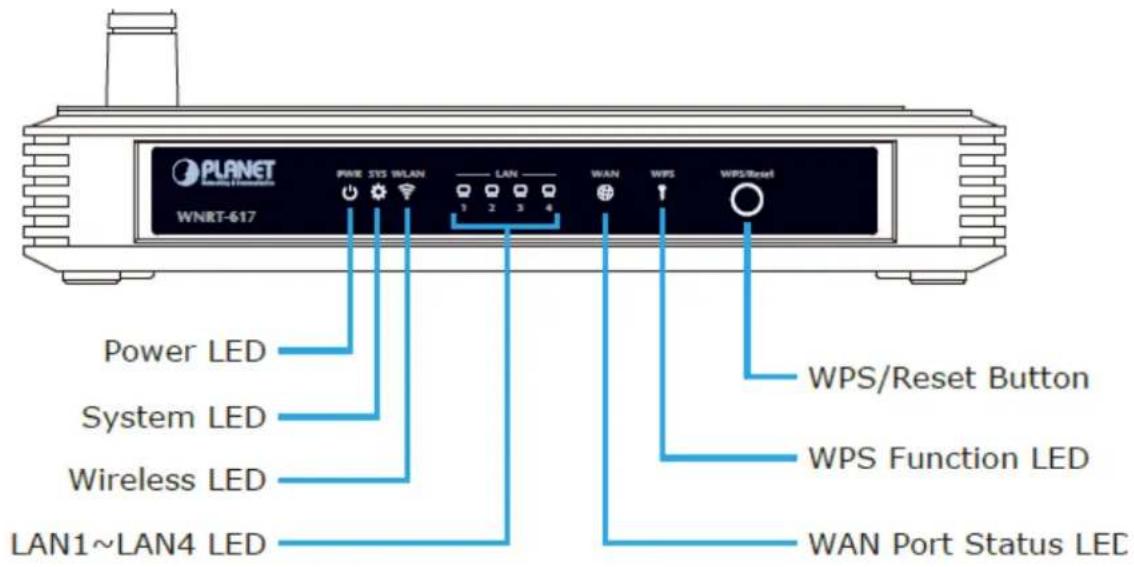
Figure 2-1 WNRT-617 Front Panel
WPS/Reset Button
| ACTIVE TIME | |
| WPS | Press and hold the button for less than 5 seconds for WPS configuration |
| Reset | Press and hold the button for more than 8 seconds to the factory default setting |
2.1.2 LED Indications
The front panel LEDs indicates instant status of port links, wireless data activity and system power; and helps monitor and troubleshoot when needed. Figure 2-2 shows the LED indications of the Wireless Router.
LED Definition

Figure 2-2 WNRT-617 Front Panel
| LED Status Function | ||
| PWR | On Power is on. | |
| Off Power is off. | ||
| SYS | On The Router is initializing. | |
| Flashing The Router is working properly. | ||
| Off The Router has a system error. | ||
| WLAN | Flashing The Wireless function is enabled. | |
| Off The Wireless function is disabled. | ||
| LAN1-4 | On A device is linked to the corresponding port but there is no activity. | |
| Flashing An active device is linked to the corresponding port. | ||
| Off No device is linked to the corresponding port. | ||
| WAN | On A device is linked to the corresponding port but there is no activity. | |
| Flashing An active device is linked to the corresponding port. | ||
| Off No device is linked to the WAN port. | ||
| WPS | Slow Flashing | A wireless device is connecting to the network by WPS function. This process will last for about 2 minutes. |
| On | A wireless device has been successfully added to the network by WPS function. The LED will keep on for about 5 minutes. | |
| Quick Flashing | A wireless device has failed to be added to the network by WPS function. | |

- When a device has been successfully added to the network by WPS function, the WPS LED will keep on for about 5 minutes and then turn off.
- When pressing and holding the WPS/Reset Button for more than 5 seconds, you will reset the router.
2.1.3 The Rear Panel
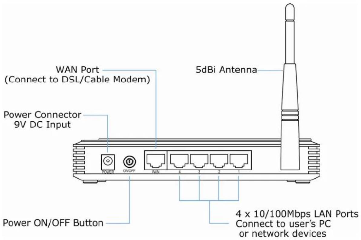
Figure 2-3 Rear Panel
| Interface Function | |
| POWER | The power socket is where you will connect the power adapter.Please use the power adapter provided with WNRT-617. |
| ON/OFF The button of the power. | |
| WAN Connect to the DSL/cable Modem, or Ethernet | |
| 1,2,3,4 (LAN) Connect to the user's PC or network devices | |
Chapter 3. Connecting the Router
3.1 System Requirements
- Broadband Internet Access Service (DSL/Cable/Ethernet connection)
One DSL/Cable Modem that has an RJ-45 connector (not necessary if the Router is connected directly to the Ethernet.) - PCs with a working Ethernet Adapter and an Ethernet cable with RJ-45 connectors
PC of subscribers running Windows 98/ME, NT4.0, 2000/XP, Windows Vista / Win 7, MAC OS 9 or later, Linux, UNIX or other platform compatible with TCP/IP protocols
The above PC is installed with WEB Browser

It is recommended to use Internet Explore 7.0 or above to access the Router.
3.2 Installing the Router
Before installing the Router, make sure your PC is connected to the Internet through the broadband service successfully at this moment. If there is any problem, please contact your local ISP. After that, please install the Router according to the following steps. Don't forget to pull out the power plug and keep your hands dry.
Step 1. Power off your PC, Cable/DSL Modem, and the Router.
Step 2. Locate an optimum location for the Router. The best place is usually at the center of your wireless network.
Step 3. Adjust the direction of the antenna. Normally, upright is a good direction.
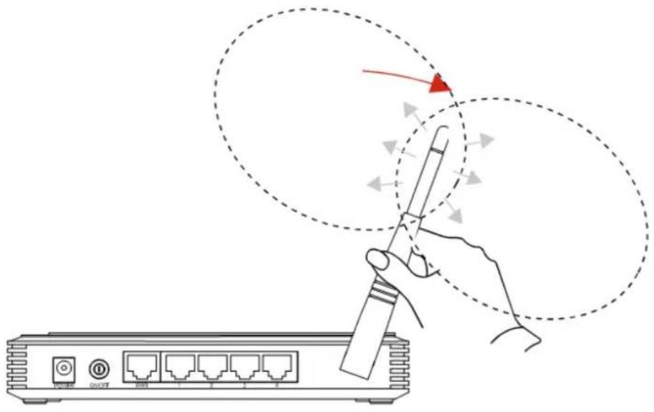
Figure 3-1 Adjust the direction of the antenna
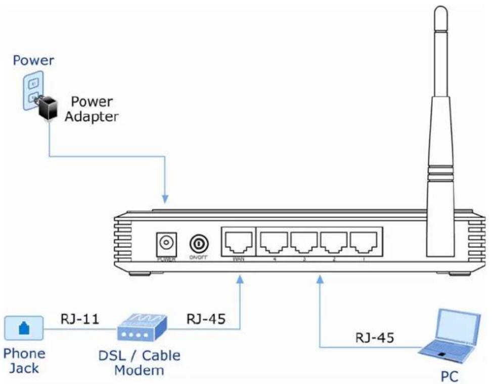
Step 4. Connect the PC or Switch/Hub in your LAN to the LAN Ports (Yellow ports) of the Router with Ethernet cable as shown in Figure 3-2.
flowchart
graph TD
    A["Power"] --> B["Power Adapter"]
    B --> C["DSL / Cable Modem"]
    C --> D["RJ-45"]
    D --> E["PC"]
    F["Phone Jack"] --> G["RJ-11"]
    G --> C
    H["Power"] --> I["POWER"]
    I --> J["ON/RT"]
    J --> K["4"]
    J --> L["3"]
    J --> M["2"]
    J --> N["1"]
Figure 3-2 Hardware Installation of the WNRT-617 Wireless Router
Step 5. Connect the power adapter to the power socket on the Router, and the other end into an electrical outlet. Then power on the Router.
Step 6. Power on your PC and Cable/DSL Modem.
Chapter 4. Quick Installation Guide
This chapter will show you how to configure the basic functions of your wireless broadband router using Quick Setup within minutes.

A computer with wired Ethernet connection to the Wireless Router is required for the first-time configuration.
4.1 Manual Network Setup - TCP/IP Configuration
The default IP address of the WNRT-617 is 192.168.1.1. And the default Subnet Mask is 255.255.255.0. These values can be changed as you desire. In this guide, we use all the default values for description.
Connect the local PC to the LAN ports of the Router. And then you can configure the IP address for your PC in the following two ways.
■ Obtain an IP address automatically
■ Configure the IP address manually
In the following sections, we'll introduce how to install and configure the TCP/IP correctly in Windows XP. First, make sure your Ethernet Adapter is working, and refer to the Ethernet adapter's manual if needed.
4.1.1 Obtain an IP Address Automatically
Summary:
■ Set up the TCP/IP Protocol in "Obtain an IP address automatically" mode on your PC.
■ Then the WNRT-617 built-in DHCP server will assign IP address to the PC automatically.
1. Install TCP/IP component
1) On the Windows taskbar, click the Start button, point to Control Panel, and then click it.
2) Under the Network and Internet icon, click on the View network status and tasks. And then click Change adapter settings.
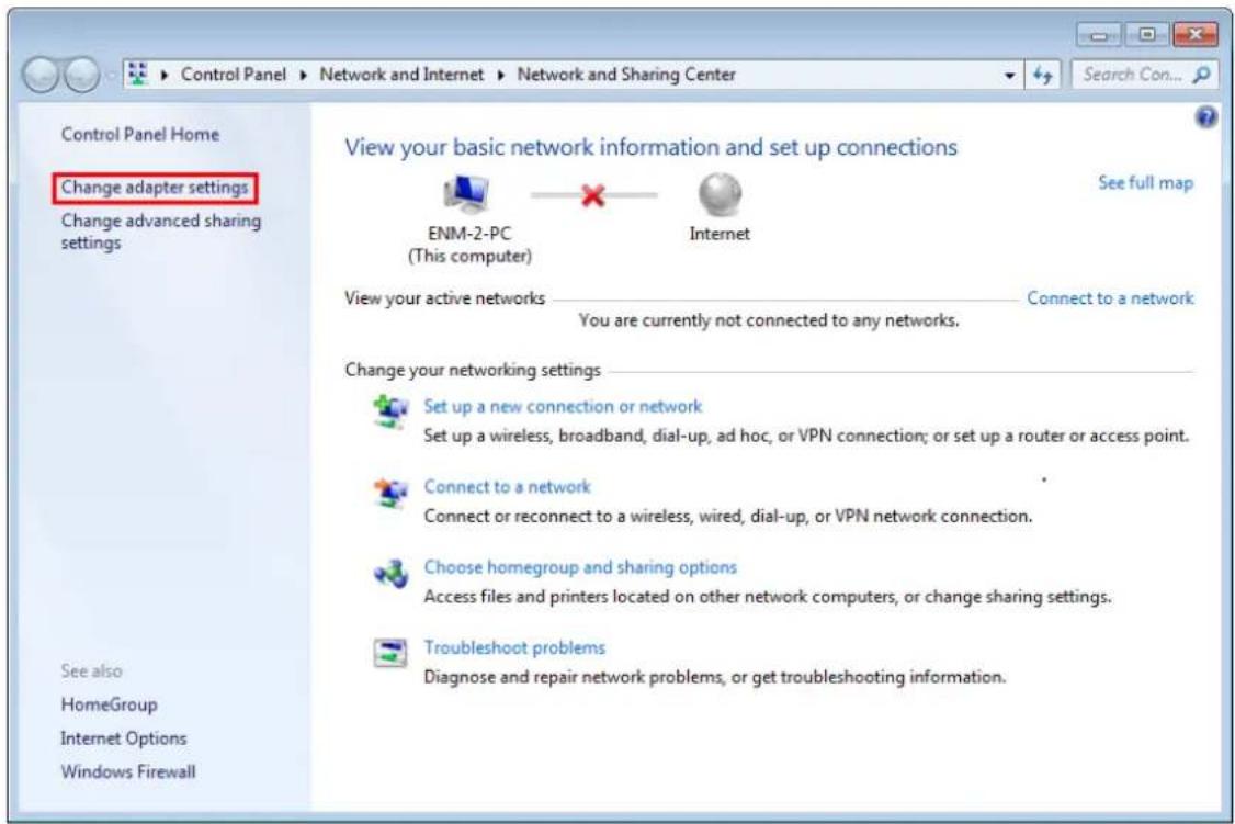
Figure 4-1 Change adapter settings
3) Right-click on the Wireless Network Connection, and select Properties in the appearing window.
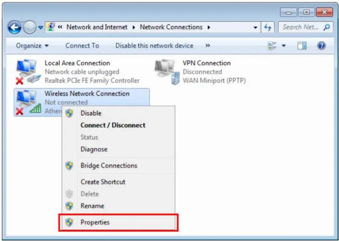
Figure 4-2 Network Connection Properties
4) In the prompt window shown below, double click on the Internet Protocol Version 4 (TCP/IPv4).
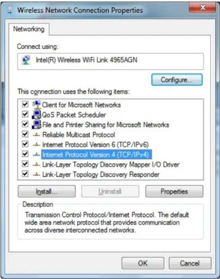
Figure 4-3 TCP/IP Setting
5) Choose Obtain an IP address automatically, and Obtain DNS server address automatically as shown in the figure below. Then click OK to save your settings.
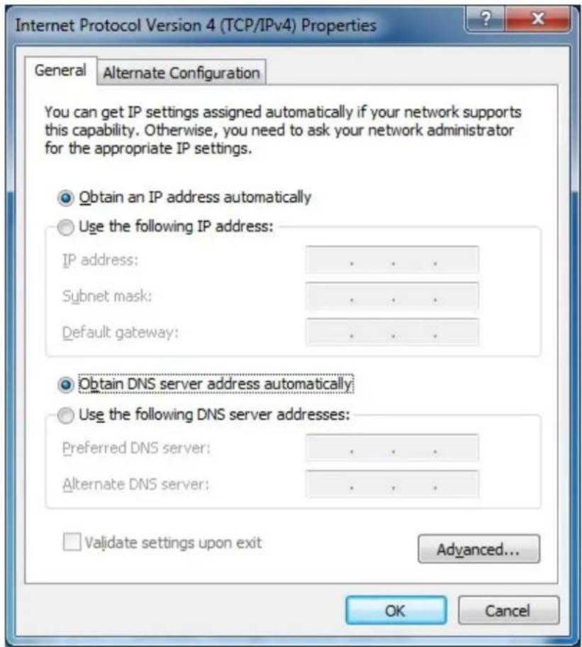
Figure 4-4 Obtain an IP address automatically
4.1.2 Configure the IP Address Manually
Summary:
■ Set up the TCP/IP Protocol for your PC.
Configure the network parameters. The IP address is 192.168.1.xxx ("xxx" is any number from 2 to 254), Subnet Mask is 255.255.255.0, and Gateway is 192.168.1.1 (The Router's default IP address)
1) Continue the settings from the last figure, select Use the following IP address radio button.
2) If the LAN IP address of the WNRT-627 is 192.168.1.1, enter IP address 192.168.1.x (x is from 2 to 254), and Subnet mask 255.255.255.0.
3) Enter the LAN IP address of the WNRT-627 (the default IP is 192.168.1.1) into the Default gateway field.
4) Select Use the following DNS server addresses radio button. In the Preferred DNS Server field,
you can enter the DNS server IP address provided by your local ISP. Then click OK to save your settings.
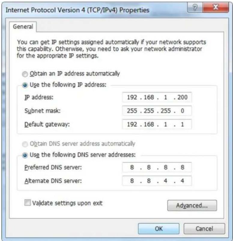
Figure 4-5 Use Static IP address
Now, you can run the Ping command in the command prompt to verify the network connection between your PC and the Router. The following example is in Windows 7 OS. Please follow the steps below:
- Click on Start
- Type "cmd" in the Search box.
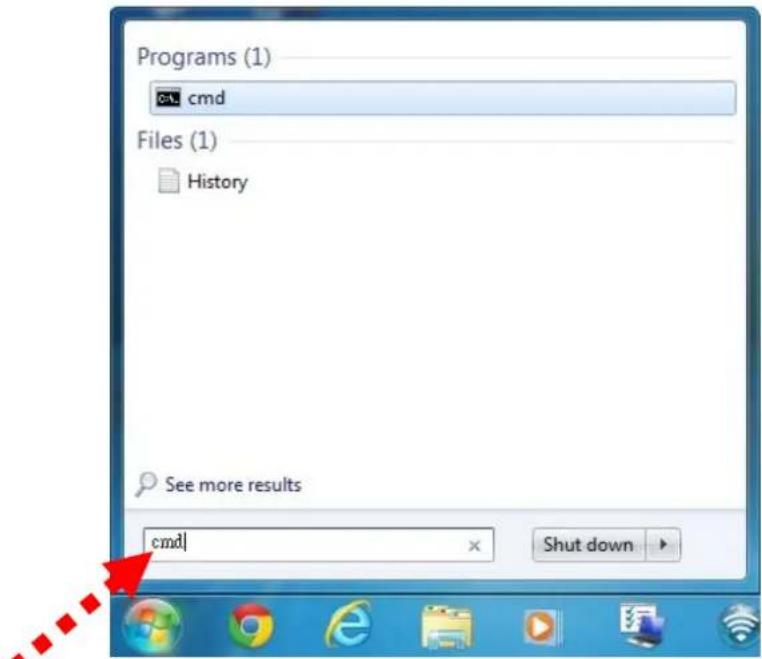
Figure 4-6 Windows 7 - Search box
- Open a command prompt, and type ping 192.168.1.1, and then press Enter.
If the result displayed is similar to Figure 4-7, it means the connection between your PC and the Router has been established well.
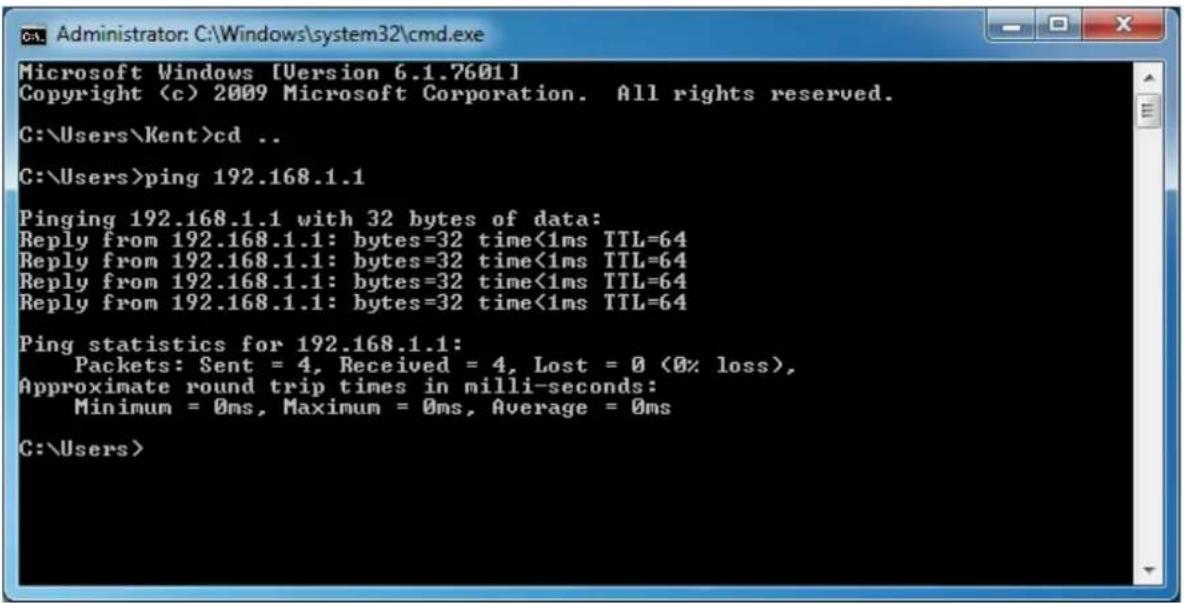
Figure 4-7 Successful result of Ping command
If the result displayed is similar to Figure 4-8, it means the connection between your PC and the Router has failed.
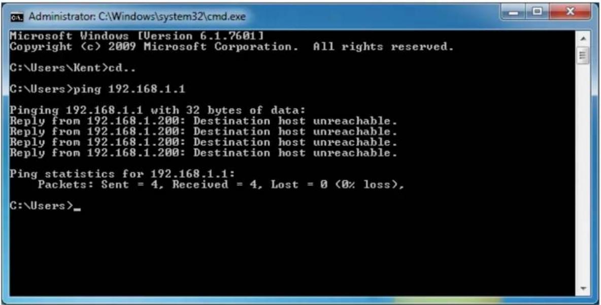
Figure 4-8 Failed result of Ping command
If the address is 0.0.0.0, check your adapter installation, security settings, and the settings on your router. Some firewall software programs may block a DHCP request on newly installed adapters.

- The 1/2/3/4 LEDs of LAN ports which you link to on the Router and LEDs on your PC's adapter should be lit.
- If the Router's IP address is 192.168.1.1, your PC's IP address must be within the range of 192.168.1.2 \~ 192.168.1.254.
4.2 Starting Setup in Web UI
It is easy to configure and manage the WNRT-617 with web browser.
Step 1. To access the configuration utility, open a web-browser and enter the default IP address http://192.168.1.1 in the address field of the browser.
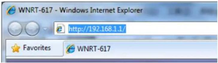
Figure 4-9 Login the Router
After a moment, a login window will appear. Enter admin for the User Name and Password, both in lower case letters. Then click the OK button or press the Enter key.
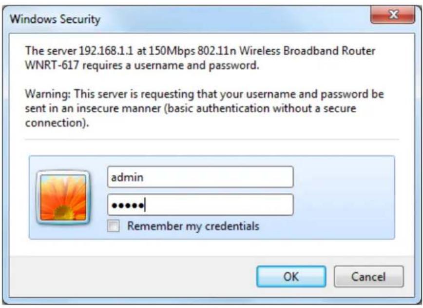
Figure 4-10 Login Window
Default User name: admin
Default Password: admin

If the above screen does not pop up, it may mean that your web-browser has been set to a proxy. Go to Tools menu>Internet Options>Connections>LAN Settings, in the screen that appears, cancel the Using Proxy checkbox, and click OK to finish it.
After entering the username and password, the main screen appears as Figure 4-11.
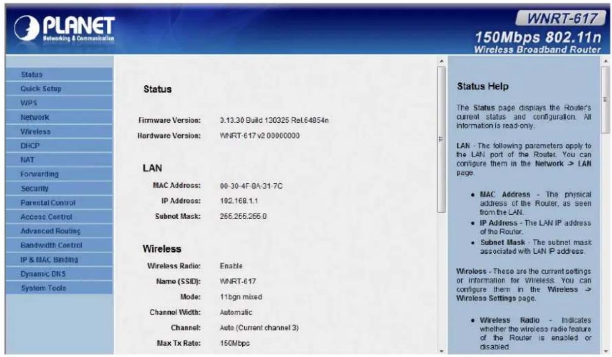
Figure 4-11 WNRT-617 Web UI Screenshot
Step 2. After successfully login in, you can click the Quick Setup to quickly configure your Router.
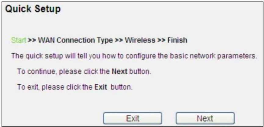
Figure 4-12 Quick Setup
Click Next, and then WAN Connection Type page will appear, shown in Figure 4-13.
Step 3. Select Auto-Detect, the Router will automatically detect the connection type your ISP provides. Make sure the cable is plugged into the WAN port before detection. The appropriate configuration page will be displayed when an active Internet service is successfully detected by the Router.
Quick Setup - WAN Connection Type
Start >> WAN Connection Type >> Wireless >> Finish
The Quick Setup is preparing to set up your connection type of WAN port.
The Router will try to detect the Internet connection type your ISP provides if you select the Auto-Detect option. Otherwise, you need to specify the connection type manually.
Auto-Detect - Let the Router automatically detect the connection type your ISP provides.
○ PPPoE - Usually for ADSL Modem and you will need a PPPoE username and password from your ISP.
Dynamic IP - Usually for Cable Modem and the router will automatically obtain an IP address from the DHCP server.
Static IP - This type of connection uses a permanent, fixed (static) IP address that your ISP assigned.
Back
Next
Figure 4-13 Quick Setup – WAN Connection Type
If the connection type detected is PPPoE, the next screen will appear as shown in Figure 4-14. Enter the User Name and Password provided by your ISP. These fields are case-sensitive. If you have difficulty with this process, please contact your ISP.
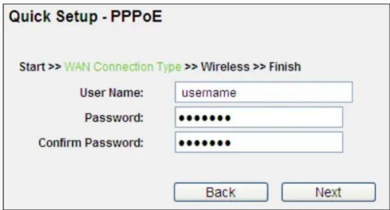
Figure 4-14 Quick Setup – PPPoE
If the connection type detected is Static IP, the next screen will appear as shown in Figure 4-15. Enter the parameters in the corresponding blanks.
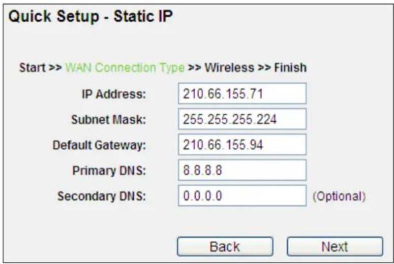
Figure 4-15 Quick Setup - Static IP
If the connection type detected is Dynamic IP, the next screen will appear as shown in Figure 4-16. Then you can go on with the wireless configuration.
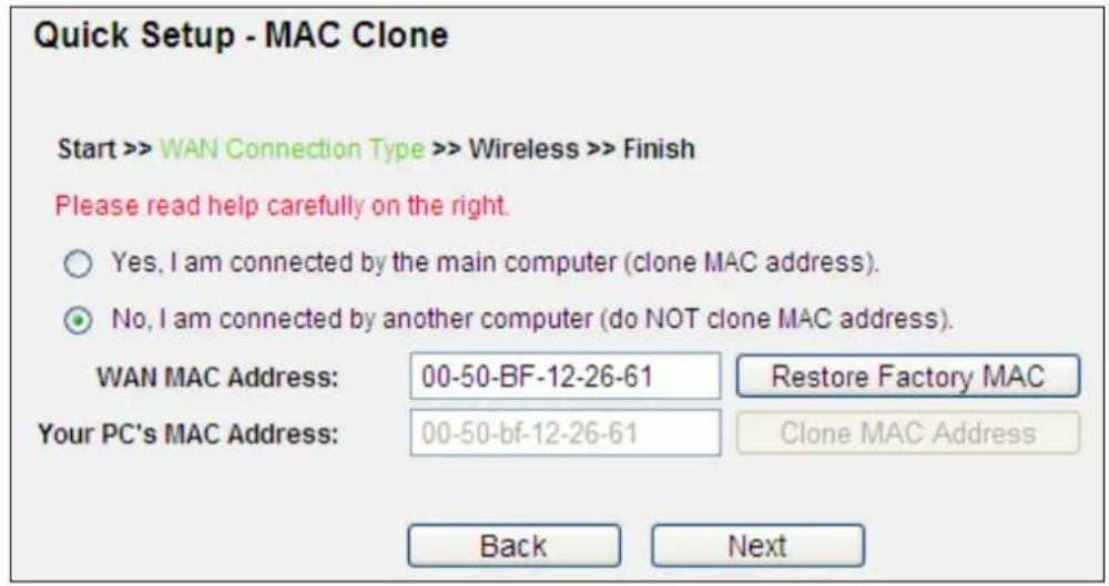
Figure 4-16 Quick Setup – MAC Clone
Step 4. Click Next to continue, the Wireless settings page will appear as shown in Figure 4-17.
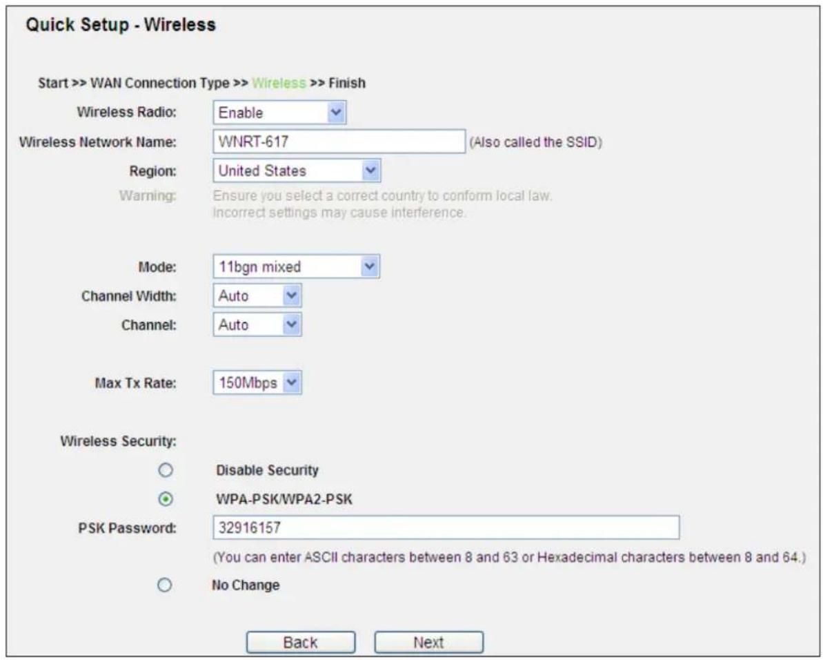
Figure 4-17 Quick Setup – Wireless
The page includes the following fields:
| Object Description | ||
| Wireless Radio Enable or disable the wireless radio choosing from the pull-down list. | ||
| Wireless Network Name (SSID) | Enter a value of up to 32 characters. The same name of SSID (Service Set Identification) must be assigned to all wireless devices in your network. Considering your wireless network security, the default SSID is set to be default. This value is case-sensitive. For example, PLANET is NOT the same as planet. | |
| Region | Select your region from the pull-down list. This field specifies the region where the wireless channel of the router can be used. | |
| Channel This field determines which operating frequency will be used. The default channel is set to Auto, so the router will choose the best channel automatically. It is not necessary to change the wireless channel unless you notice interference problems with another nearby access point. | ||
| Mode This field determines the wireless mode which the Router works on. | ||
| Channel Width | Select any channel width from the pull-down list. The default setting is automatic, which can adjust the channel width for your clients automatically. | |
| Max Tx Rate | You can limit the maximum transmission rate of the Router through this field. | |
| Wireless Security | Disable Security | The wireless security function can be enabled or disabled. If disabled, the wireless stations will be able to connect to the Router without encryption. It is recommended strongly that you choose one of following options to enable security. |
| WPA-PSK / WPA2-PSK | WPA-PSK/WPA2-PSK - Select WPA based on pre-shared passphrase.PSK Password - You can enter ASCII or Hexadecimal characters.For ASCII, the key can be made up of any numbers 0 to 9 and any letters A to Z, the length should be between 8 and 63 characters.For Hexadecimal, the key can be made up of any numbers 0 to 9 and letters A to F, the length should be between 8 and 64 characters.Please also note the key is case-sensitive. | |
| No Change | If you choose this option, wireless security configuration will not change. | |
These settings are only for basic wireless parameters. For advanced settings, please refer to Chapter 5.7 Wireless.
Step 5. Click the Next button. You will then see the Finish page.
If you don't make any change on the Wireless page, you will see the Finish page as shown in Figure 4-18. Click the Finish button to finish the Quick Setup.
Quick Setup - Finish
Congratulations! The Router is now connecting you to the Internet. For detail settings, please click other menus if necessary.
Back
Finish
Figure 4-18 Quick Setup – Finish (No wireless parameter changed)
If there is something changed on the Wireless page, you will see the Finish page as shown in Figure 4-19. Click the Reboot button to make your wireless configuration to take effect and finish the Quick Setup.
Quick Setup - Finish
Congratulations! The Router is now connecting you to the Internet. For detail settings, please click other menus if necessary.
The change of wireless config will not take effect until the Router reboot.
Back
Reboot
Figure 4-19 Quick Setup – Finish (Reboot is required)
After the rebooting, please check whether you can access the Internet or not in the 5.2 Status page.
4.3 PLANET Smart Setup! Utility
You can configure the Wireless Router by running the SMART SETUP in the CD-ROM provided in the package.
To setup through the Smart Setup! program, insert the CD into your Windows XP / Vista / Win 7 PC and follow the instructions on the screen.
Step 1. Power on the Cable/DSL Modem.
Step 2. Connect the WAN port (Blue port) of the WNRT-617 to the Cable/DSL Modem with RJ-45 UTP Ethernet cable.
Step 3. Connect the PC LAN port to the LAN Ports (Yellow ports) of the WNRT-617 with RJ-45 UTP Ethernet cable, shown in Figure 4-20.
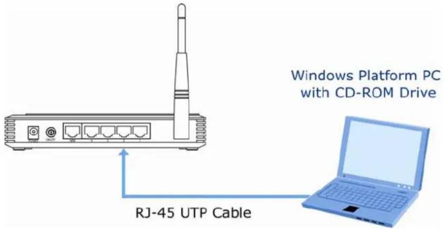
Figure 4-20 LAN Port connection of the WNRT-617 Wireless Router
Step 4. Connect the power adapter to the power socket on the WNRT-617, and the other end into an electrical outlet. Then power on the Wireless Router.
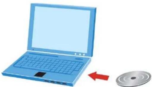
Step 5. Insert the CD into your Windows platform PC and follow the instructions on the screen to quickly setup for the Internet connection..
natural_image
Illustration of a blue laptop with a CD/DVD nearby, showing a red arrow indicating rotation (no text or symbols)Figure 4-21 Insert the CD to the laptop
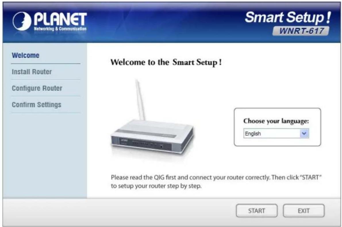
Figure 4-22 PLANET Smart Setup! Program screenshot
Chapter 5. Configuring the Router
This chapter will show each Web page's key functions and the configuration way.
5.1 Login
After successfully login, you will see the fifteen main menus on the left of the Web-based utility. On the right, there are the corresponding explanations and instructions.
| Status |
| Quick Setup |
| Operation Mode |
| WPS |
| Network |
| Wireless |
| DHCP |
| NAT |
| Forwarding |
| Security |
| Parental Control |
| Access Control |
| Advanced Routing |
| Bandwidth Control |
| IP & MAC Binding |
| Dynamic DNS |
| System Tools |
Figure 5-1 Main Menu
The detailed explanations for each Web page's key function are listed below.
5.2 Status
The Status page provides the current status information about the Router. All information is read-only.
| Status | |
| Firmware Version: | 3.13.30 Build 130325 Rel.64854n |
| Hardware Version: | WNRT-617 v2 00000000 |
| LAN | |
| MAC Address: | 00-30-4F-8A-31-7C |
| IP Address: | 192.168.1.1 |
| Subnet Mask: | 255.255.255.0 |
| Wireless | |
| Wireless Radio: | Enable |
| Name (SSID): | WNRT-617 |
| Mode: | 11bgn mixed |
| Channel Width: | Automatic |
| Channel: | Auto (Current channel 3) |
| Max Tx Rate: | 150Mbps |
Figure 5-2 Router Status
5.3 Quick Setup
Please refer to Section 4.2: Starting Setup in Web UI.
5.4 Operation Mode
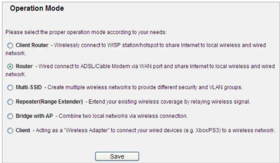
Figure 5-3 Operation Mode
The page includes the following fields:
| Object Description | |
| Client Router | In this mode, the device enables multiusers to share Internet from WISP. The LAN port devices share the same IP from WISP through Wireless port. While connecting to WISP, the Wireless port works as a WAN port at AP Client Router mode. The ethernet port acts as a LAN port. |
| Router | In this mode, the device enables multiusers to share Internet via ADSL/Cable Modem.The wireless port share the same IP to ISP through ethernet WAN port. The Wireless port acts the same as a LAN port while at AP Router mode. |
| Multi-SSID | In this mode, the device can create up to 4 wireless networks labeled with different SSIDs and assign each SSID with different security or VLAN, especially for the situation when the various access policies and functions are required. |
| Repeater(Range Extender) | In this mode, the device can copy and reinforce the existing wireless signal to extend the coverage of the signal, especially for a large space to eliminate signal-blind corners. |
| Bridge with AP | In this mode, the device can be used to combine multiple local networks together to the same one via wireless connections, especially for a home or office where separated networks can't be connected easily together with a cable. |
| Client | In this mode, the device can be connected to another device via Ethernet port and act as an adaptor to grant your wired devices access to a wireless network, especially for a Smart TV, Media Player, or game console only with an Ethernet port. |
Be sure to click the Save button to save your settings on this page.

The device will reboot automatically after you click the Save button.
When you change the operation mode to Client/Repeater, WPS function will stay disabled. Please manually enable this function if needed when you switch back to Access Point/Multi-SSID/Bridge mode.
5.5 WPS
This section will guide you to add a new wireless device quickly to an existing network by WPS (Wi-Fi Protected Setup) function.
Step 1. Choose menu "WPS", you will see the next screen (shown in Figure 5-4).
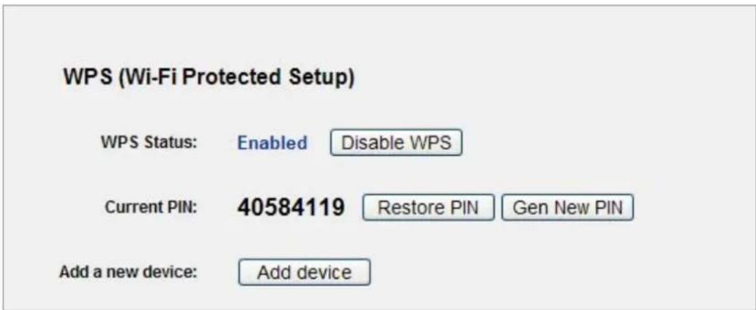
Figure 5-4 WPS
The page includes the following fields:
| Object Description | |
| WPS Status | Enable or disable the WPS function here. |
| Current PIN | The current value of the Router's PIN displayed here. The default PIN of the Router can be found in the label or User Guide. |
| Restore PIN | Restore the PIN of the Router to its default. |
| Gen New PIN | Click this button, and then you can get a new random value for the Router's PIN. You can ensure the network security by generating a new PIN. |
| Add device | You can add the new device to the existing network manually by clicking this button. |
Step 2. To add a new device:
If the wireless adapter supports Wi-Fi Protected Setup (WPS), you can establish a wireless connection between wireless adapter and Router using either Push Button Configuration (PBC) method or PIN method.

To build a successful connection by WPS, you should also do the corresponding configuration of the new device for WPS function.
I. By Push Button Configuration (PBC)
If the wireless adapter supports Wi-Fi Protected Setup and the Push Button Configuration (PBC) method, you can add it to the network by PBC with the following two methods.
Step 1: Press the WPS/Reset Button on the front panel of the Router.

Figure 5-5 Hardware WPS/Reset Button
Or you can keep the default WPS Status as Enabled and click the Add device button in Figure 5-6, then the following screen will appear.
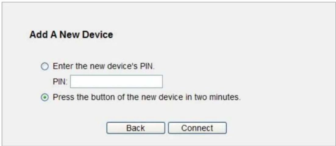
Figure 5-6 Software WPS/Reset Button
Choose Press the button of the new device in two minutes, and click Connect.

When pressing and holding the WPS/Reset Button on the router for more than 5 seconds, you will reset the router.
Step 2: Press and hold the WPS Button equipped on the adapter directly for 2 or 3 seconds. Or you can click the WPS button with the same function in the configuration utility of the adapter.
Step 3: Wait for a while until the next screen appears. Click Finish to complete the WPS configuration.
II. By PIN
If the new device supports Wi-Fi Protected Setup and the PIN method, you can add it to the network by PIN with the following two methods.
Method One: Enter the PIN of your Wireless adapter into the configuration utility of the Router
Step 1: Keep the default WPS Status as Enabled and click the Add device button in Figure 5-7, then the following screen will appear.
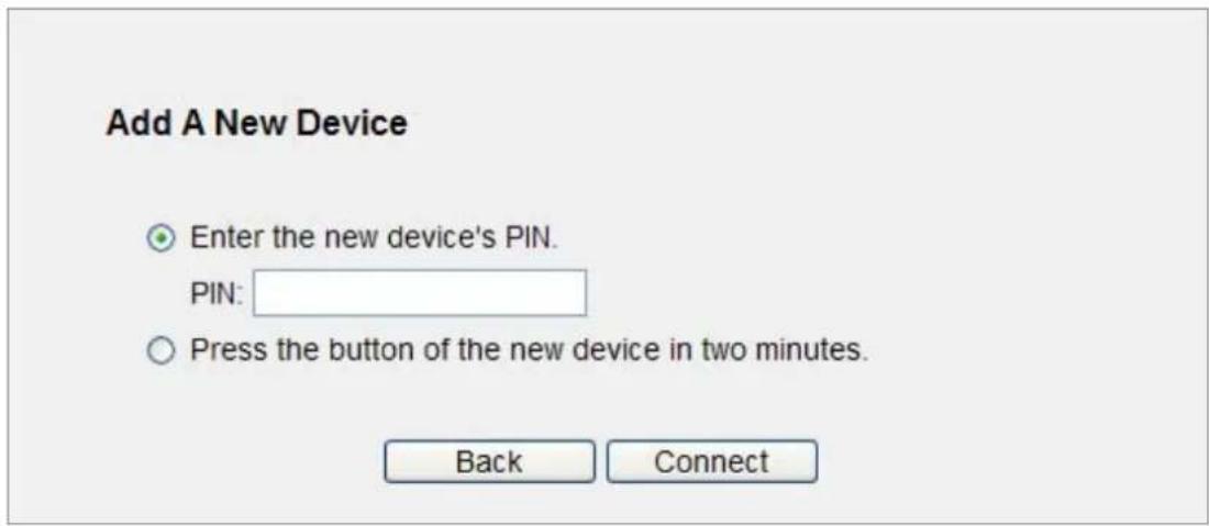
Figure 5-7 Add a new device
Step 2: Choose Enter the new device's PIN and enter the PIN code of the wireless adapter in the field behind PIN in the above figure. Then click Connect.

The PIN code of the adapter is always displayed on the WPS configuration screen.
Step 3: For the configuration of the wireless adapter, please choose the option that you want to enter PIN into the Router in the configuration utility of the WPS, and click Next.
Method Two: Enter the PIN of the Router into the configuration utility of your Wireless adapter
Step 1: Get the Current PIN code of the Router in Figure 5-4 (each Router has its unique PIN code).
Step 2: For the configuration of the wireless adapter, please choose the option that you want to enter the PIN of the Router in the configuration utility of the Wireless adapter, and enter it into the field. Then click Next.

The default PIN code of the Router can be found in WPS configuration screen as shown in Figure 5-4.
Step 3. You will see the following screen when the new device has successfully connected to the network.
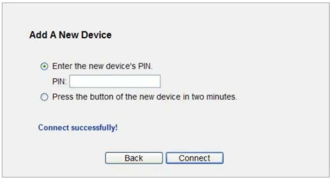
Figure 5-8 New device connected successfully

1) The WPS LED on the Router will light in green for about 5 minutes if the device has been successfully added to the network.
2) The WPS function cannot be configured if the Wireless Function of the Router is disabled. Please make sure the Wireless Function is enabled before configuring the WPS.
5.6 Network
There are three submenus under the Network menu (shown in Figure 5-9): WAN, LAN, and MAC Clone. Click any of them, and you will be able to configure the corresponding function.
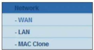
Figure 5-9 The Network menu
5.6.1 WAN
Choose menu "Network→WAN", you can configure the IP parameters of the WAN on the screen below.

If you don't know how to choose the appropriate connection type, click the Detect button to allow the Router to automatically search your Internet connection for servers and protocols. The connection type will be reported when an active Internet service is successfully detected by the Router. This detect result is for your reference only. To make sure the connection type your ISP provides, please refer to the ISP. The various types of Internet connections that the Router can detect are as follows:
- PPPoE - Connections which use PPPoE that requires a user name and password.
Dynamic IP - Connections which use dynamic IP address assignment.
Static IP - Connections which use static IP address assignment.
The Router cannot detect PPTP / L2TP / BigPond connections with your ISP. If your ISP uses one of these protocols, then you must configure your connection manually.
■ Dynamic IP
- If your ISP provides the DHCP service, please choose Dynamic IP type, and the Router will automatically obtain IP parameters from your ISP. You can see the page as follows (Figure 5-10):
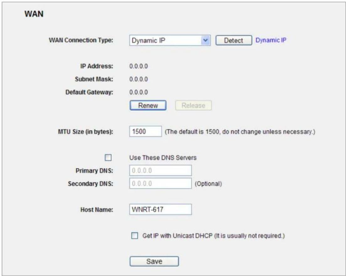
Figure 5-10 WAN - Dynamic IP
This page displays the WAN IP parameters assigned dynamically by your ISP, including IP address, Subnet Mask, Default Gateway, etc. Click the Renew button to renew the IP parameters from your ISP. Click the Release button to release the IP parameters.
| Object Description | |
| MTU Size | The normal MTU (Maximum Transmission Unit) value for most Ethernet networks is 1500 Bytes. It is not recommended that you change the default MTU Size unless required by your ISP. |
| Use These DNS Servers | If your ISP gives you one or two DNS addresses, select Use These DNS Servers and enter the primary and secondary addresses into the correct fields. Otherwise, the DNS servers will be assigned dynamically from your ISP. |
| Host Name | This option specifies the Host Name of the Router. |
| Get IP with Unicast DHCP | A few ISPs' DHCP servers do not support the broadcast applications. If you cannot get the IP Address normally, you can choose this option. (It is rarely required.) |

If you get "Address not found" error when you access a Website, it is likely that your DNS servers are set up improperly. You should contact your ISP to get the correct DNS server address.
■ Static IP
- If your ISP provides a static or fixed IP Address, Subnet Mask, Gateway and DNS setting, select Static IP. The Static IP settings page will appear, shown in Figure 5-11.
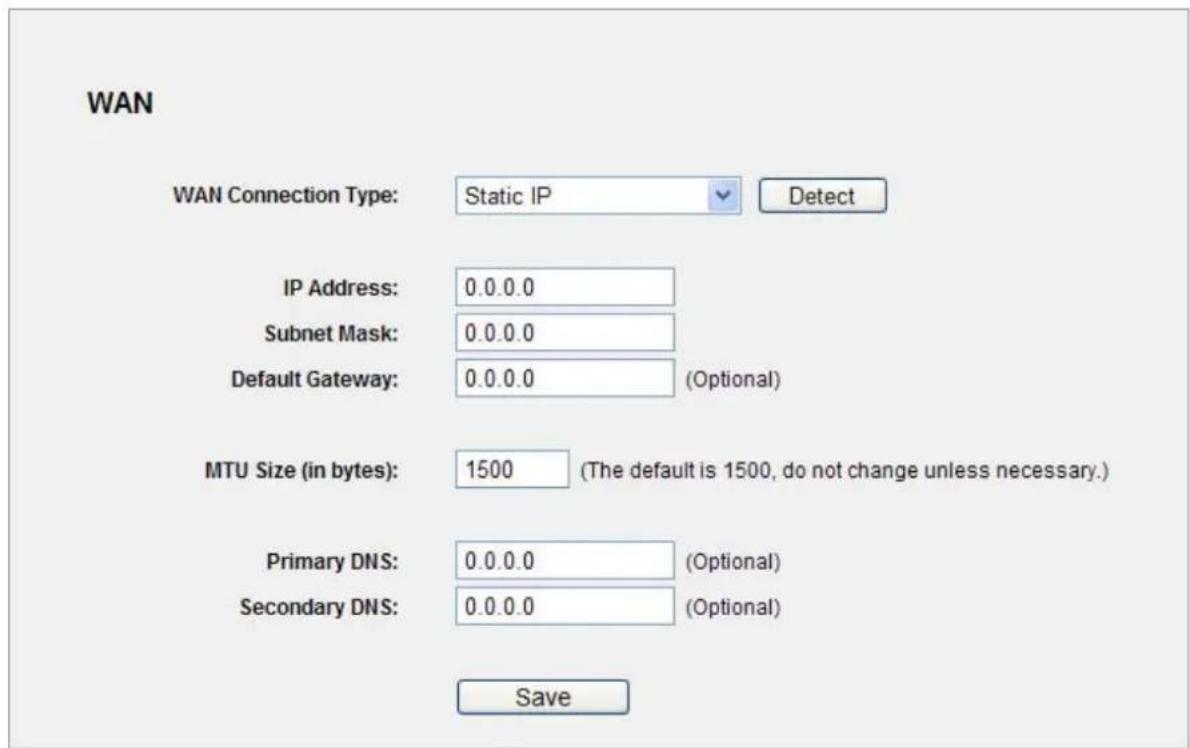
Figure 5-11 WAN - Static IP
The page includes the following fields:
| Object Description | |
| IP Address | Enter the IP address in dotted-decimal notation provided by your ISP. |
| Subnet Mask | Enter the subnet Mask in dotted-decimal notation provided by your ISP, usually is 255.255.255.0 |
| Default Gateway | (Optional) Enter the gateway IP address in dotted-decimal notation provided by your ISP. |
| MTU Size | The normal MTU (Maximum Transmission Unit) value for most Ethernet networks is 1500 Bytes. It is not recommended that you change thedefault MTU Size unless required by your ISP. |
| Primary/Secondary DNS | (Optional) Enter one or two DNS addresses in dotted-decimal notation provided by your ISP. |
■ PPPoE / Russia PPPoE
- If your ISP provides a PPPoE / Russia PPPoE connection, select PPPoE/Russia PPPoE option. And enter the following parameters (Figure 5-12):
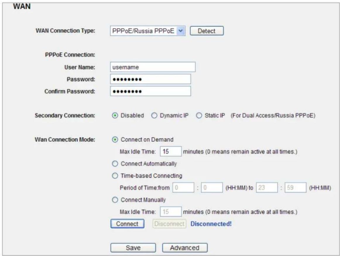
Figure 5-12 WAN – PPPoE
The page includes the following fields:
| Object Description | ||
| User Name/Password | Enter the User Name and Password provided by your ISP. These fields are case-sensitive. | |
| Secondary Connection | Disabled | The Secondary Connection is disabled by default, so there is PPPoE connection only. This is recommended. |
| Dynamic IP | You can check this radio button to use Dynamic IP as the secondary connection to connect to the local area network provided by ISP. | |
| Static IP | You can check this radio button to use Static IP as the secondary connection to connect to the local area network provided by ISP. | |
| Connect on Demand | In this mode, the Internet connection can be terminated automatically after a specified inactivity period (Max Idle Time) and be re-established when you attempt to access the Internet again. If you want your Internet connection to keep active all the time, please enter "0" in the Max Idle Time field. Otherwise, enter the number of minutes you want to have elapsed before your Internet access disconnects. | |
| Connect Automatically | The connection can be re-established automatically when it was down. | |
| Time-based Connecting | The connection will only be established in the period from the start time to the end time (both are in HH:MM format).Note:Only when you have configured the system time on System Tools -> Time page can the Time-based Connecting function take effect. | |
| Connect Manually | You can click the Connect/ Disconnect button to connect/disconnect immediately. This mode also supports the Max Idle Time function as Connect on Demand mode. The Internet connection can be disconnected automatically after a specified inactivity period and re-established when you attempt to access the Internet again. | |

Sometimes the connection cannot be terminated although you specify a time to Max Idle Time, since some applications are visiting the Internet continually in the background.
If you want to do some advanced configurations, please click the Advanced button, and the page shown in Figure 5-13 will then appear:
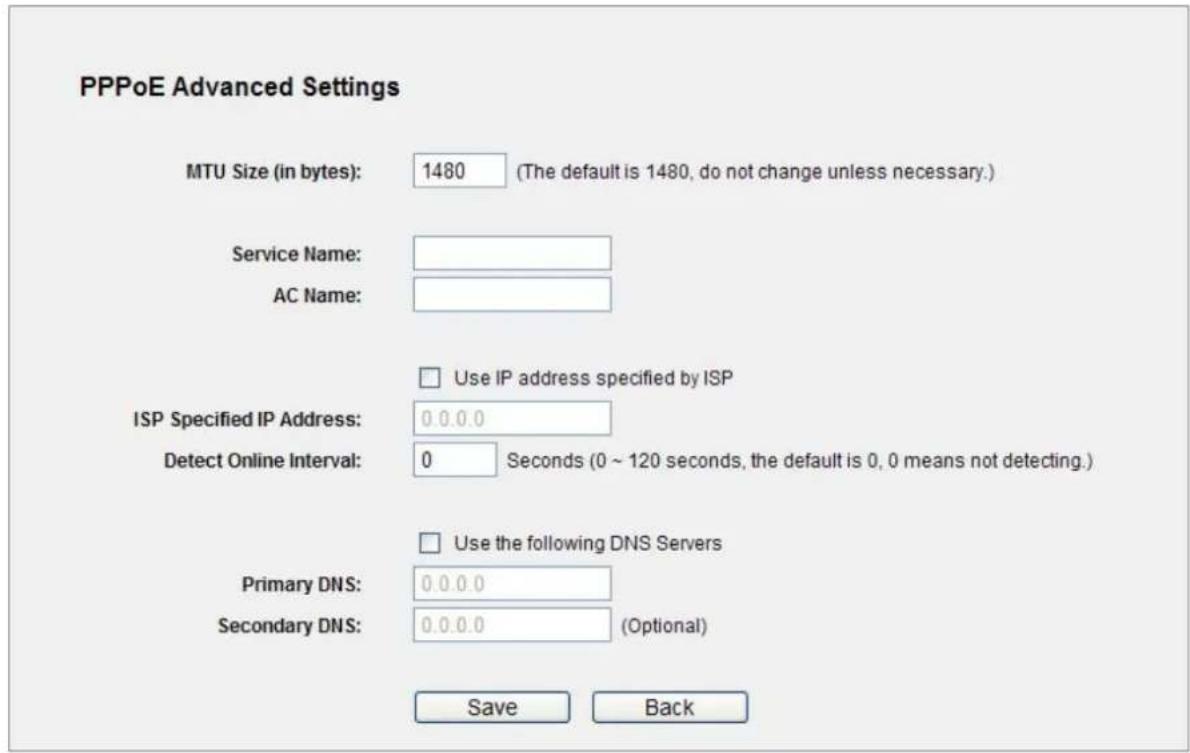
Figure 5-13 PPPoE Advanced Settings
The page includes the following fields:
| Object Description | |
| MTU Size The default MTU size is “1480” bytes, which is usually fine. It is not recommended that you change the default MTU Size unless required by your ISP. | |
| Service Name/AC Name | The service name and AC (Access Concentrator) name, which should not be configured unless you are sure it is necessary for your ISP. In most cases, leaving these fields blank will work. |
| ISP Specified IP Address | If your ISP does not automatically assign IP addresses to the Router during login, please click “Use IP address specified by ISP” check box and enter the IP address provided by your ISP in dotted-decimal notation. |
| Detect Online Interval | The Router will detect Access Concentrator online at every interval. The default value is “0”. You can input the value between “0” and “120”. The value “0” means no detect. |
| DNS IP address | If your ISP does not automatically assign DNS addresses to the Router during login, please click “Use the following DNS servers” check box and enter the IP address in dotted-decimal notation of your ISP’s primary DNS server. If a secondary DNS server address is available, enter it as well. |
Click the Save button to save your settings.
■ BigPond Cable
- If your ISP provides BigPond Cable (or Heart Beat Signal) connection, please select BigPond Cable. And you should enter the following parameters (Figure 5-14):
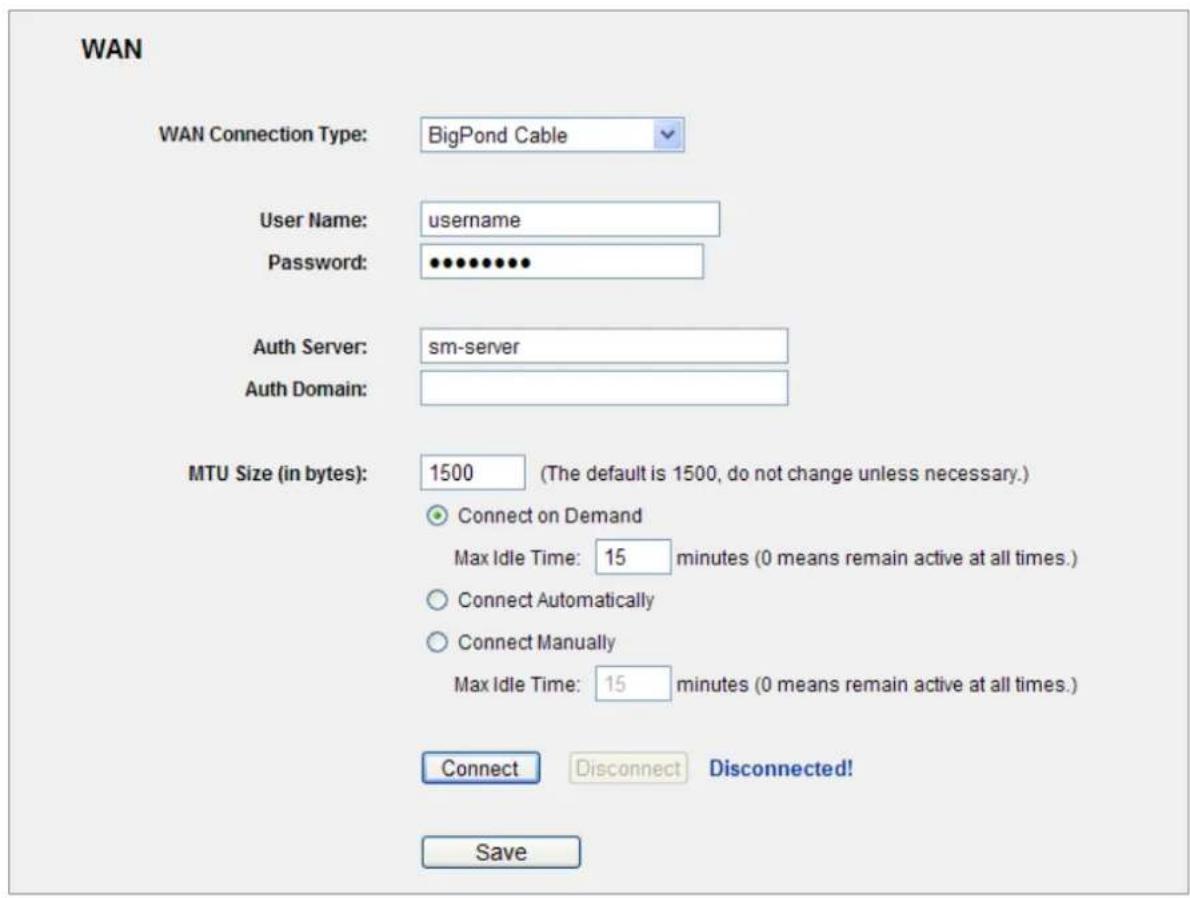
Figure 5-14 WAN – BigPond Cable
The page includes the following fields:
| Object Description | |
| User Name/Password | Enter the User Name and Password provided by your ISP. These fields are case-sensitive. |
| Auth Server | Enter the authenticating server IP address or host name. |
| Auth Domain | Type in the domain suffix server name based on your location.e.g.NSW / ACT - nsw.bigpond.net.auVIC / TAS / WA / SA / NT - vic.bigpond.net.auQLD - qld.bigpond.net.au |
| MTU Size | The normal MTU (Maximum Transmission Unit) value for most Ethernet networks is 1500 Bytes. It is not recommended that youchange the default MTU Size unless required by your ISP. |
| Connect on Demand | In this mode, the Internet connection can be terminated automatically after a specified inactivity period (Max Idle Time) and be re-established when you attempt to access the Internet again. If you want your Internet connection to keep active all the time, please enter “0” in the Max Idle Time field. Otherwise, enter the number of minutes you want to have elapsed before your Internet access disconnects. |
| Connect Automatically | The connection can be re-established automatically when it was down. |
| Connect Manually | You can click the Connect/Disconnect button to connect/disconnect immediately. This mode also supports the Max Idle Time function as Connect on Demand mode.The Internet connection can be disconnected automatically after a specified inactivity period and re-established when you attempt to access the Internet again.Click the Connect button to connect immediately.Click the Disconnect button to disconnect immediately. |
Click the Save button to save your settings.

Sometimes the connection cannot be terminated although you specify a time to Max Idle Time, since some applications are visiting the Internet continually in the background.
■ L2TP / Russia L2TP
- If your ISP provides L2TP / Russia L2TP connection, please select L2TP/Russia L2TP option. And enter the following parameters (Figure 5-15):
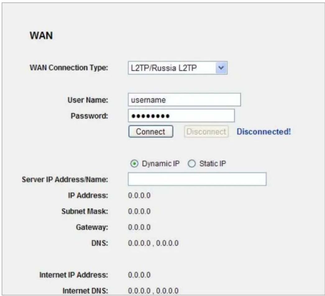
Figure 5-15 WAN - L2TP Settings
The page includes the following fields:
| Object Description | |
| User Name/Password | Enter the User Name and Password provided by your ISP. These fields are case-sensitive. |
| Dynamic IP/ Static IP | Choose either as you are given by your ISP. Click the Connect button to connect immediately.Click the Disconnect button to disconnect immediately. |
| Connect on Demand You can configure the Router to disconnect from your Internet connection after a specified period of inactivity (Max Idle Time). If your Internet connection has been terminated due to inactivity, Connect on Demand enables the Router to automatically re-establish your connection as soon as you attempt to access the Internet again. If you | |
| wish to activateConnect on Demand, click the radio button. If you want your Internet connection to remain active at all times, enter 0 in theMax Idle Timefield. Otherwise, enter the number of minutes you want to have elapsed before your Internet connection terminates. | |
| Connect Automatically | Connect automatically after the Router is disconnected. To use this option, click the radio button. |
| Connect Manually | You can configure the Router to make it connect or disconnect manually. After a specified period of inactivity (Max Idle Time), the Router will disconnect from your Internet connection, and you will not be able to re-establish your connection automatically as soon as you attempt to access the Internet again.To use this option, click the radio button.If you want your Internet connection to remain active at all times, enter "0" in theMax Idle Timefield. Otherwise, enter the number in minutes that you wish to have the Internet connecting last unless a new link is requested. |
Click the Save button to save your settings.

Sometimes the connection cannot be terminated although you specify a time to Max Idle Time, since some applications are visiting the Internet continually in the background.
■ PPTP / Russia PPTP
- If your ISP provides PPTP / Russia PPTP connection, please select PPTP/Russia PPTP option. And enter the following parameters (Figure 5-16):
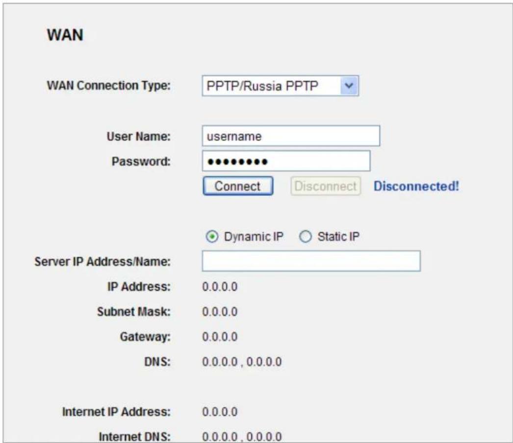
Figure 5-16 WAN - PPTP Settings
The page includes the following fields:
| Object Description | |
| User Name/Password | Enter the User Name and Password provided by your ISP. These fields are case-sensitive. |
| Dynamic IP/ Static IP | Choose either as you are given by your ISP and enter the ISP's IP address or the domain name.If you choose static IP and enter the domain name, you should also enter the DNS assigned by your ISP. And click theSavebutton.Click theConnectbutton to connect immediately. Click theDisconnectbutton to disconnect immediately. |
| Connect on Demand | You can configure the Router to disconnect from your Internet connection after a specified period of inactivity (Max Idle Time). If yourInternet connection has been terminated due to inactivity,Connect on Demandenables the Router to automatically re-establish your connection as soon as you attempt to access the Internet again.If you wish to activateConnect on Demand, click the radio button.If you want your Internet connection to remain active at all times, enter 0 in theMax Idle Timefield. Otherwise, enter the number of minutes you want to have elapsed before your Internet connection terminates. |
| Connect Automatically | Connect automatically after the Router is disconnected. To use this option, click the radio button. |
| Connect Manually | You can configure the Router to make it connect or disconnect manually. After a specified period of inactivity (Max Idle Time), the Router will disconnect from your Internet connection, and you will not be able to re-establish your connection automatically as soon as you attempt to access the Internet again. To use this option, click the radio button. If you want your Internet connection to remain active at all times, enter "0" in theMax Idle Timefield. Otherwise, enter the number in minutes that you wish to have the Internet connecting last unless a new link is requested. |

Sometimes the connection cannot be terminated although you specify a time to Max Idle Time, since some applications are visiting the Internet continually in the background.
5.6.2 LAN
Choose menu "Network→LAN", you can configure the IP parameters of the LAN on the screen as below.
LAN
MAC Address: 00-30-4F-20-F3-CC
IP Address: 192.168.1.1
Subnet Mask: 255.255.255.0
Save
Figure 5-17 LAN Settings
The page includes the following fields:
| Object Description | |
| MAC Address | The physical address of the Router, as seen from the LAN. The value can't be changed. |
| IP Address | Enter the IP address of your Router or reset it in dotted-decimal notation (factory default: 192.168.1.1). |
| Subnet Mask | An address code that determines the size of the network. Normally use 255.255.255.0 as the subnet mask. |

- If you change the IP Address of LAN, you must use the new IP Address to login the Router.
- If the new LAN IP Address you set is not in the same subnet, the IP Address pool of the DHCP server will change accordingly at the same time, while the Virtual Server and DMZ Host will not take effect until they are re-configured.
5.6.3 MAC Clone
Choose menu "Network→ MAC Clone", you can configure the MAC address of the WAN on the screen below (Figure 5-18).
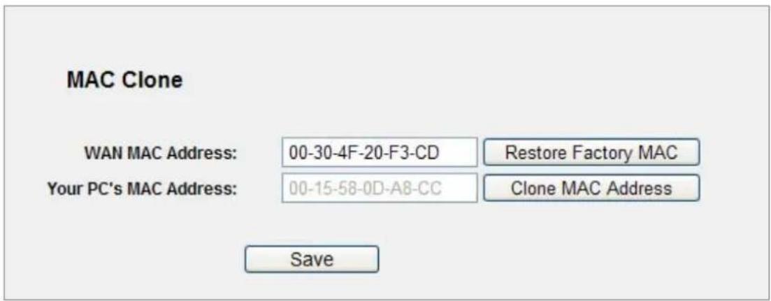
Figure 5-18 MAC Address Clone
Some ISPs require that you register the MAC Address of your adapter. Changes are rarely needed here.
The page includes the following fields:
| Object Description | |
| WAN MAC Address | This field displays the current MAC address of the WAN port. If your ISP requires you to register the MAC address, please enter the correct MAC address into this field in XX-XX-XX-XX-XX format(X is any hexadecimal digit).ClickRestore Factory MACto restore the MAC address of WAN port to the factory default value. |
| Your PC's MAC Address | This field displays the MAC address of the PC that is managing the Router. If the MAC address is required, you can click theClone MAC Addressbutton and this MAC address will fill in theWAN MAC Addressfield. |
Click the Save button to save your settings.

Only the PC on your LAN can use the MAC Address Clone function.
5.7 Wireless
There are five submenus under the Wireless menu (shown in Figure 5-19): Wireless Settings, Wireless Security, Wireless MAC Filtering, Wireless Advanced and Wireless Statistics. Click any of them, and you will be able to configure the corresponding function.
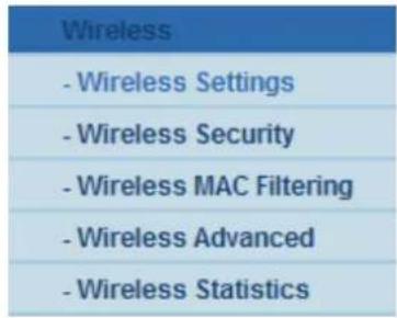
Figure 5-19 Wireless menu
5.7.1 Wireless Settings
Choose menu "Wireless→Wireless Settings", you can configure the basic settings for the wireless network on this page.
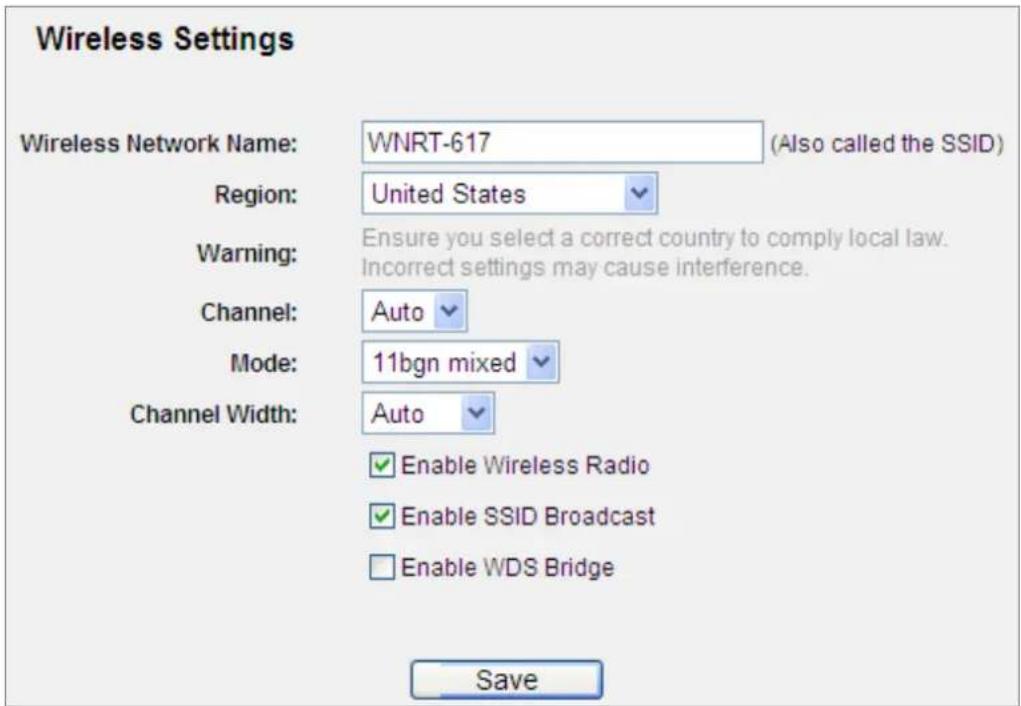
Figure 5-20 Wireless Settings
The page includes the following fields:
| Object Description | |
| Wireless Network Name (SSID) | Enter a value of up to 32 characters. The same name of SSID (Service Set Identification) must be assigned to all wireless devices in your network. Considering your wireless network security, the default SSID is set to be default. This value is case-sensitive. For example, PLANET is NOT the same as planet. |
| Region | Select your region from the pull-down list. This field specifies the region where the wireless function of the Router can be used. It may be illegal to use the wireless function of the Router in a region other than one of those specified in this field. If your country or region is not listed, please contact your local government agency for assistance.When you select your local region from the pull-down list, click the Save button, then the Note Dialog appears. Click OK. |
 Note DialogNote:Limited by local law regulations, version for North America does not have region selection option. Note DialogNote:Limited by local law regulations, version for North America does not have region selection option. | |
| Channel | This field determines which operating frequency will be used. The default channel is set to Auto, so the AP will choose the best channel automatically. It is not necessary to change the wireless channel unless you notice interference problems with another nearby access point. |
| Mode | Select the desired mode. The default setting is 11bgn mixed.11b only, 11g only, 11n only, 11bg mixed, 11bgn mixed.It is strongly recommended that you set the Mode to 802.11b&g&n, and all of 802.11b, 802.11g, and 802.11n wireless stations can connect to the Router. |
| Channel width | Select any channel width from the pull-down list. The default setting is automatic, which can adjust the channel width for your clients automatically. |
| Max Tx Rate | You can limit the maximum tx rate of the Router through this field. |
| Enable Wireless Router Radio | The wireless radio of this Router can be enabled or disabled to allow wireless stations access. |
| Enable SSID Broadcast | When wireless clients survey the local area for wireless networks to associate with, they will detect the SSID broadcast by the Router. If you select the Enable SSID Broadcast checkbox, the Wireless Router will broadcast its name (SSID) on the air. |

If 11b only, 11g only, or 11bg mixed is selected in the Mode field, the Channel Width selecting field will turn grey and the value will become 20M, which is unable to be changed.
| Object Description | |
| Enable WDS | Check this box to enable WDS. With this function, the Router can bridge two or more WLANs. If this checkbox is selected, you will have to set the following parameters as shown below. Make sure the following settings are correct. |
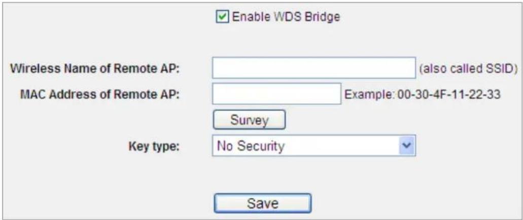
Figure 5-21 WDS Settings
The page includes the following fields:
| Object Description | |
| SSID(to be bridged) | The SSID of the AP your Router is going to connect to as a client. You can also use the search function to select the SSID to join. |
| BSSID(to be bridged) | The BSSID of the AP your Router is going to connect to as a client. You can also use the search function to select the BSSID to join. |
| Search | Click this button, you can search the AP which runs in the current channel. |
| Key type | This option should be chosen according to the AP's security configuration. It is recommended that the security type is the same as your AP's security type. |
| WEP Index | This option should be chosen if the key type is WEP(ASCII) or WEP(HEX).It indicates the index of the WEP key. |
| Auth Type | This option should be chosen if the key type is WEP(ASCII) or WEP(HEX).It indicates the authorization type of the Root AP. |
| Password | If the AP your Router is going to connect needs password, you need to fill the password in this blank. |
5.7.2 Wireless Security
Choose menu "Wireless→Wireless Security", and you can configure the security settings of your wireless network.
There are five wireless security modes supported by the Router:
■ WEP (Wired Equivalent Privacy)
■ WPA (Wi-Fi Protected Access)
■ WPA2 (Wi-Fi Protected Access 2)
■ WPA-PSK (Pre-Shared Key)
■ WPA2-PSK (Pre-Shared Key)
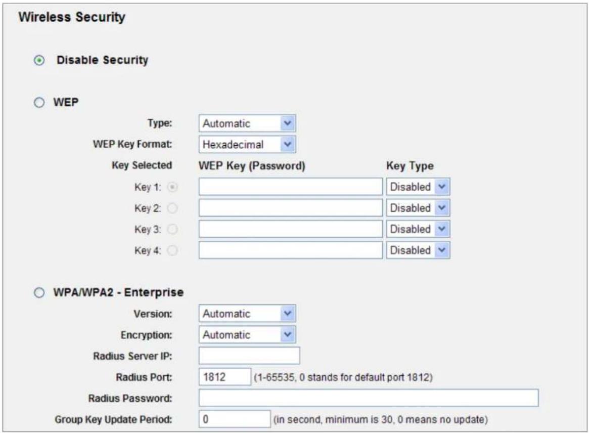
Figure 5-22 Wireless Security - None
The page includes the following fields:
| Object Description | |
| Disable Security | If you do not want to use wireless security, select this check box, but it's strongly recommended to choose one of the following modes to enable security. |
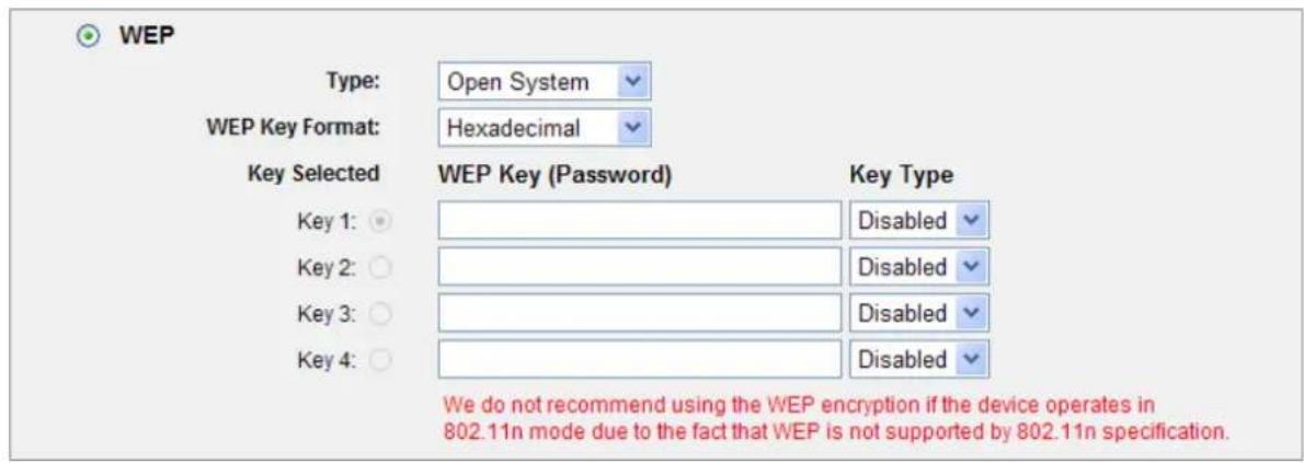
Figure 5-23 Wireless Security - WEP
| Object Description | ||
| WEP | It is based on the IEEE 802.11 standard. If you select this check box, you will find a notice in red as show in Figure 5-23. | |
| Type | you can choose the type for the WEP security on the pull-down list. The default setting is Automatic, which can select Open System or Shared Key authentication type automatically based on the wireless station's capability and request. | |
| WEP Key Format | Hexadecimal and ASCII formats are provided. Hexadecimal format stands for any combination of hexadecimal digits (0-9, a-f, A-F) in the specified length. ASCII format stands for any combination of keyboard characters in the specified length. | |
| WEP Key | Select which of the four keys will be used and enter the matching WEP key that you create. Make sure these values are identical on all wireless stations in your network. | |
| Key Type | You can select the WEP key length (64-bit, or 128-bit, or 152-bit.) for encryption."Disabled" means this WEP key entry is invalid. | |
| 64-bit You can | enter 10 hexadecimal digits (any combination of 0-9, a-f, A-F, zero key is not promoted) or 5 ASCII characters. | |
| 128-bit You can | enter 26 hexadecimal digits (any combination of 0-9, a-f, A-F, zero key is not promoted) or 13 ASCII characters. | |
| 152-bit You can | enter 32 hexadecimal digits (any combination of 0-9, a-f, A-F, zero key is not promoted) or 16 ASCII characters. | |

If you do not set the key, the wireless security function is still disabled even if you have selected Shared Key as Authentication Type.
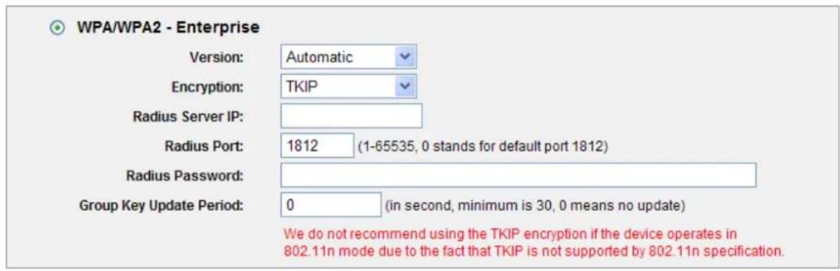
Figure 5-24 Wireless Security - WPA/WPA2 Enterprise
The page includes the following fields:
| Object Description | |
| WPA/WPA2 | It is based on Radius Server. |
| Version | you can choose the version of the WPA security on the pull-down list.The default setting is Automatic, which can select WPA (Wi-Fi Protected Access) or WPA2 (WPA version 2) automatically based on the wireless station's capability and request. |
| Encryption | You can select either Automatic, or TKIP or AES. |
| Radius Server IP | Enter the IP address of the Radius Server. |
| Radius Port | Enter the port that radius service used. |
| Radius Password | Enter the password for the Radius Server. |
| Group Key Update Period | Specify the group key update interval in seconds. The value should be 30 or above. Enter 0 to disable the update. |

If you check the WPA/WPA2 radio button and choose TKIP encryption, you will find a notice in red as shown in Figure 5-24.
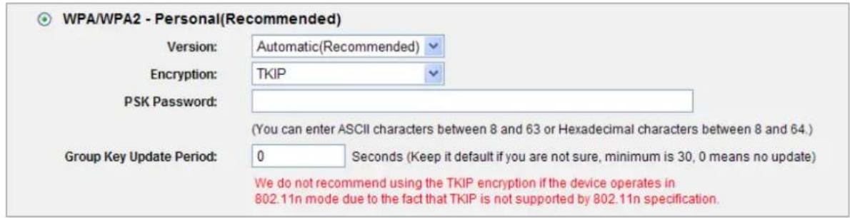
Figure 5-25 Wireless Security - WPA/WPA2 Personal
The page includes the following fields:
| Object Description | |
| WPA-PSK/WPA2-PSK | It's the WPA/WPA2 authentication type based on pre-shared passphrase. |
| Version | you can choose the version of the WPA-PSK security on the drop-down list. The default setting is Automatic, which can select WPA-PSK (Pre-shared key of WPA) or WPA2-PSK (Pre-shared key of WPA) automatically based on the wireless station's capability and request. |
| Encryption | When WPA-PSK or WPA is set as the Authentication Type, you can select either Automatic, or TKIP or AES as Encryption. |
| PSK Password | You can enter ASCII characters between 8 and 63 characters or 8 to 64 Hexadecimal characters. |
| Group Key Update Period | Specify the group key update interval in seconds. The value should be 30 or above. Enter 0 to disable the update. |
Be sure to click the Save button to save your settings on this page.

If you check the WPA-PSK/WPA2-PSK radio button and choose TKIP encryption, you will find a notice in red as shown in Figure 5-25.
5.7.3 Wireless MAC Filtering
Choose menu "Wireless→MAC Filtering", you can control the wireless access by configuring the Wireless MAC Address Filtering function, shown in Figure 5-26.
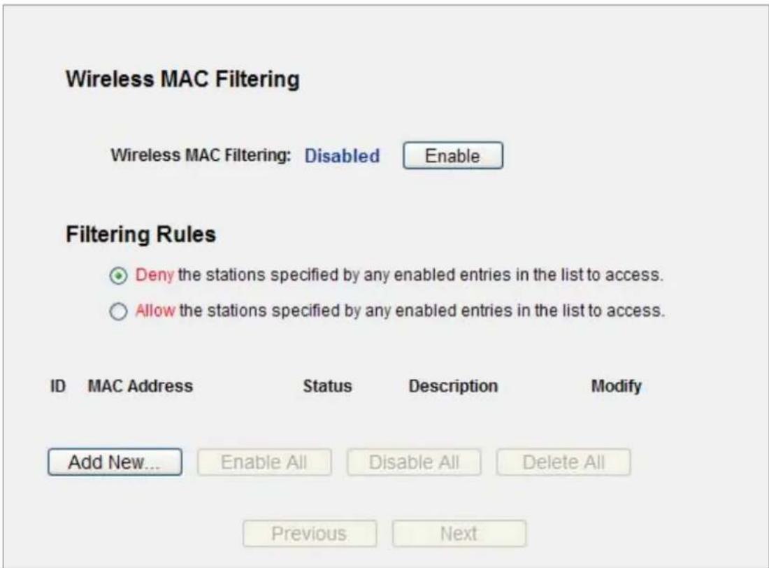
Figure 5-26 Wireless MAC Address Filtering
To filter wireless users by MAC Address, click Enable. The default setting is Disable.
| Object Description | |
| MAC Address | The wireless station's MAC address that you want to filter. |
| Status | The status of this entry either Enabled or Disabled. |
| Description | A simple description of the wireless station. |
To Add a Wireless MAC Address filtering entry, click the Add New... button. The "Add or Modify Wireless MAC Address Filtering entry" page will appear as shown in Figure 5-27:
Add or Modify Wireless MAC Address Filtering entry
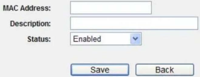
Figure 5-27 Add or Modify Wireless MAC Address Filtering entry
To add or modify a MAC Address Filtering entry, follow these instructions:
Step 1. Enter the appropriate MAC Address into the MAC Address field. The format of the MAC Address is XX-XX-XX-XX-XX-XX (X is any hexadecimal digit). For example: 00-30-4F-11-22-33.
Step 2. Enter a simple description of the wireless station in the Description field. For example: Wireless station A.
Step 3. Status - Select Enabled or Disabled for this entry on the Status pull-down list.
Step 4. Click the Save button to save this entry.
To modify or delete an existing entry:
Step 1. Click the Modify in the entry you want to modify. If you want to delete the entry, click the Delete.
Step 2. Modify the information.
Step 3. Click the Save button.
Click the Enable All button to make all entries enabled
Click the Disabled All button to make all entries disabled.
Click the Delete All button to delete all entries
Click the Next button to go to the next page
Click the Previous button to return to the previous page.
For example: If you desire that the wireless station A with MAC address 00-30-4F-11-22-33 and the wireless station B with MAC address 00-30-4F-1A-2B-3C are able to access the Router, but all the other wireless stations cannot access the Router, you can configure the Wireless MAC Address Filtering list by following these steps:
Step 1. Click the Enable button to enable this function.
Step 2. Select the radio button: Deny the stations not specified by any enabled entries in the list to access for Filtering Rules.
Step 3. Delete all or disable all entries if there are any entries already.
Step 4. Click the Add New... button and enter the MAC address 00-30-4F-11-22-33 /00-30-4F-1A-2B-3C in the MAC Address field, then enter wireless station A/B in the Description field, while select Enabled in the Status pull-down list. Finally, click the Save and the Back button.
The filtering rules that configured should be similar to the following list:
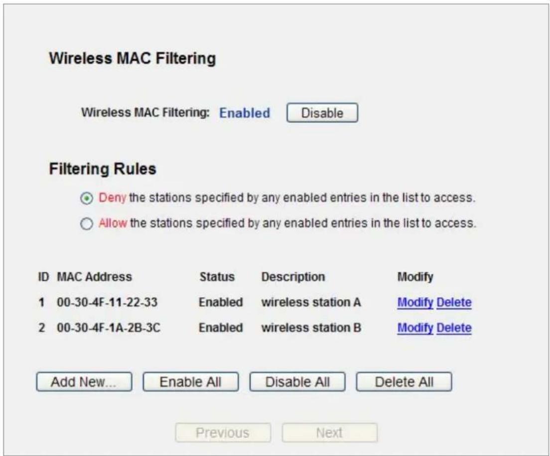
Figure 5-28 Wireless MAC Address Filtering
5.7.4 Wireless Advanced
Choose menu "Wireless→Wireless Advanced", and you can configure the advanced settings of your wireless network.
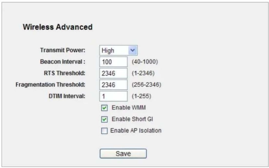
Figure 5-29 Wireless Advanced
The page includes the following fields:
| Object Description | |
| Transmit Power | Here you can specify the transmit power of Router. You can select High, Middle or Low which you would like. High is the default setting and is recommended. |
| Beacon Interval | Enter a value between 20-1000 milliseconds for Beacon Interval here. The beacons are the packets sent by the router to synchronize a wireless network. Beacon Interval value determines the time interval of the beacons. The default value is 100. |
| RTS Threshold | Here you can specify the RTS (Request to Send) Threshold. If the packet is larger than the specified RTS Threshold size, the router will send RTS frames to a particular receiving station and negotiate the sending of a data frame. The default value is 2346. |
| Fragmentation Threshold | This value is the maximum size determining whether packets will be fragmented. Setting the Fragmentation Threshold too low may result in poor network performance since excessive packets. 2346 is the defaultsetting and is recommended. |
| DTIM Interval | This value determines the interval of the Delivery Traffic Indication Message (DTIM). A DTIM field is a countdown field informing clients of the next window for listening to broadcast and multicast messages. When the Router has buffered broadcast or multicast messages for associated clients, it sends the next DTIM with a DTIM Interval value. You can specify the value between 1-255 Beacon Intervals. The default value is 1, which indicates the DTIM Interval is the same as Beacon Interval. |
| Enable WMM | WMM function can guarantee the packets with high-priority messages being transmitted preferentially. It is strongly recommended enabled. |
| Enable Short GI | This function is recommended for it will increase the data capacity by reducing the guard interval time. |
| Enabled AP Isolation | This function can isolate wireless stations on your network from each other. Wireless devices will be able to communicate with the Router but not with each other. To use this function, check this box. AP Isolation is disabled by default. |

If you are not familiar with the setting items on this page, it's strongly recommended to keep the provided default values; otherwise, it may result in lower wireless network performance.
5.7.5 Wireless Statistics
Choose menu "Wireless→Wireless Statistics", and you can see the MAC Address, Current Status, Received Packets and Sent Packets for each connected wireless station.
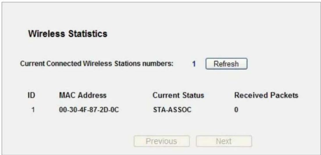
Figure 5-30 The Router attached wireless stations
The page includes the following fields:
| Object Description | |
| MAC Address | The connected wireless station's MAC address |
| Current Status | The connected wireless station's running status, one of STA-AUTH / STA-ASSOC / STA-JOINED / WPA / WPA-PSK / WPA2 / WPA2-PSK / AP-UP / AP-DOWN / Disconnected |
| Received Packets | Packets received by the station |
| Sent Packets | Packets sent by the station |
You cannot change any of the values on this page. To update this page and to show the current connected wireless stations, click on the Refresh button.
If the numbers of connected wireless stations go beyond one page, click the Next button to go to the next page and click the Previous button to return the previous page.

This page will be refreshed automatically every 5 seconds.
5.8 DHCP
There are three submenus under the DHCP menu (shown in Figure 5-31): DHCP Settings, DHCP Clients List and Address Reservation. Click any of them, and you will be able to configure the corresponding function.
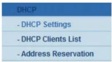
Figure 5-31 The DHCP menu
5.8.1 DHCP Settings
Choose menu “DHCP→DHCP Settings”, and you can configure the DHCP Server on the page (shown in Figure 5-32). The Router is set up by default as a DHCP (Dynamic Host Configuration Protocol) server, which provides the TCP/IP configuration for all the PC(s) that are connected to the Router on the LAN.

Figure 5-32 DHCP Settings
The page includes the following fields:
| Object Description | |
| DHCP Server | Enable or Disable the DHCP server. If you disable the Server, you must have another DHCP server within your network or else you must configure the computer manually. |
| Start IP Address | Specify an IP address for the DHCP Server to start with when assigning IP addresses. 192.168.1.100 is the default start address. |
| End IP Address | Specify an IP address for the DHCP Server to end with when assigning IP addresses. 192.168.1.199 is the default end address. |
| Address Lease Time | The Address Lease Time is the amount of time a network user will be allowed connection to the Router with their current dynamic IP Address. Enter the amount of time in minutes and the user will be "leased" this dynamic IP Address. After the time is up, the user will be automatically assigned a new dynamic IP address. The range of the time is 1 ~ 2880 minutes. The default value is 120 minutes. |
| Default Gateway | (Optional.) Suggest to input the IP address of the LAN port of the Router, default value is 192.168.1.1 |
| Default Domain | (Optional.) Input the domain name of your network. |
| Primary DNS | (Optional.) Input the DNS IP address provided by your ISP. Or consult your ISP. |
| Secondary DNS | (Optional.) Input the IP address of another DNS server if your ISP provides two DNS servers. |

To use the DHCP server function of the Router, you must configure all computers on the LAN as "Obtain an IP Address automatically" mode.
5.8.2 DHCP Clients List
Choose menu "DHCP→DHCP Clients List", and you can view the information about the clients attached to the Router in the next screen.
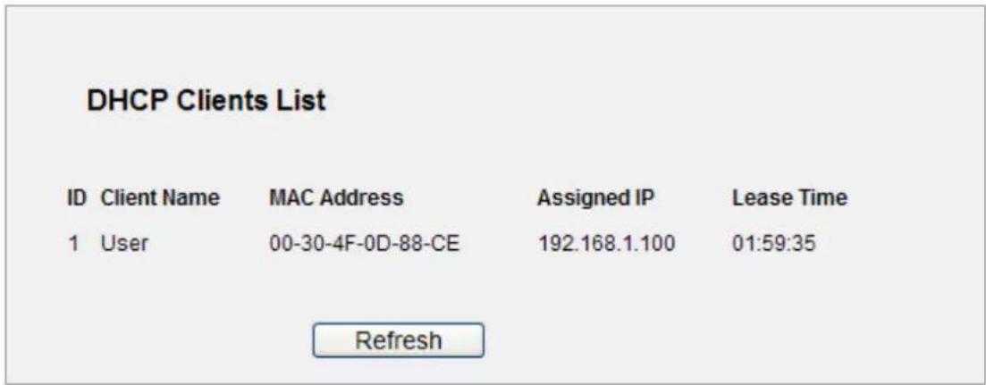
Figure 5-33 DHCP Clients List
The page includes the following fields:
| Object Description | |
| ID | The index of the DHCP Client |
| Client Name | The name of the DHCP client |
| MAC Address | The MAC address of the DHCP client |
| Assigned IP | The IP address that the Router has allocated to the DHCP client. |
| Lease Time | The time of the DHCP client leased. After the dynamic IP address has expired, a new dynamic IP address will be automatically assigned to the user. |
You cannot change any of the values on this page. To update this page and to show the current attached devices, click the Refresh button.
5.8.3 Address Reservation
Choose menu "DHCP→Address Reservation", you can view and add a reserved addresses for clients via the next screen (shown in Figure 5-34). When you specify a reserved IP address for a PC on the LAN, that PC will always receive the same IP address each time when it accesses the DHCP server. Reserved IP addresses should be assigned to the servers that require permanent IP settings.
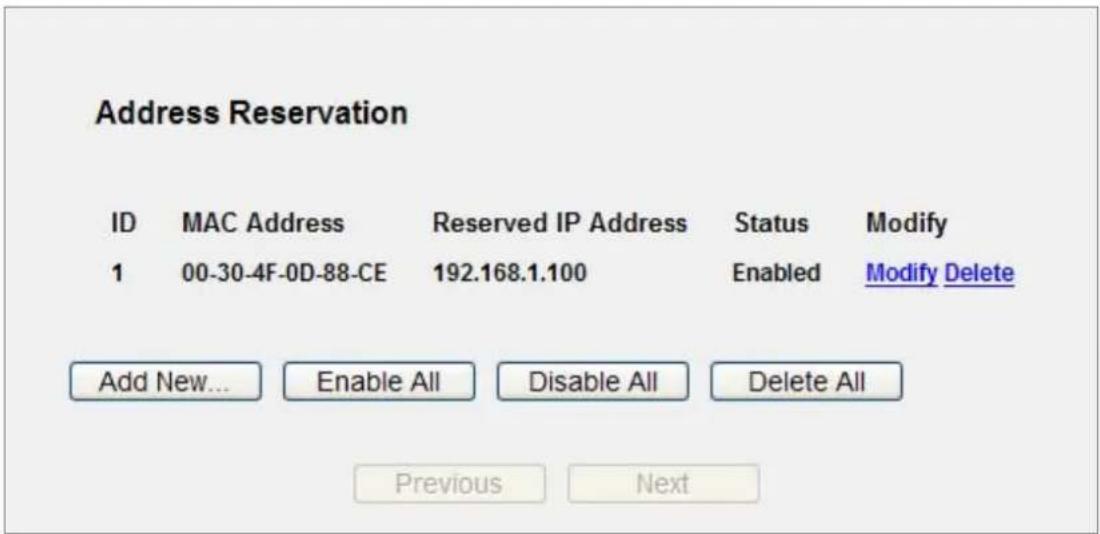
Figure 5-34 Address Reservation
The page includes the following fields:
| Object Description | |
| MAC Address | The MAC address of the PC for which you want to reserve IP address. |
| Assigned IP Address | The IP address of the Router reserved. |
| Status | The status of this entry either Enabled or Disabled. |
To Reserve IP addresses:
Step 1. Click the Add New ... button.
Step 2. Enter the MAC address (in XX-XX-XX-XX-XX-XX format.) and IP address in dotted-decimal notation of the computer you wish to add.
Step 3. Click the Save button when finished.
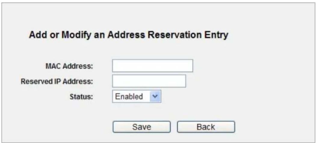
Figure 5-35 Add or Modify an Address Reservation Entry
To modify or delete an existing entry:
Step 1. Click the Modify in the entry you want to modify. If you want to delete the entry, click the Delete.
Step 2. Modify the information.
Step 3. Click the Save button.
Click the Enable/ Disabled All button to make all entries enabled/disabled
Click the Delete All button to delete all entries
Click the Next button to go to the next page and Click the Previous button to return the previous page.
5.9 NAT
To select NAT function to manage WNRT-617 as to how to avoid physical IP address that is too long.
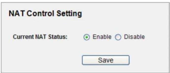
Figure 5-36 NAT Function
The page includes the following fields:
| Object Description | |
| Enable | The virtual IP address can connect to Internet through NAT function. |
| Disable | Only uses physical IP address to link Internet. |
5.10 Forwarding
There are four submenus under the Forwarding menu (shown in Figure 5-37): Virtual Servers, Port Triggering, DMZ and UPnP. Click any of them, and you will be able to configure the corresponding function.
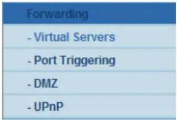
Figure 5-37 The Forwarding menu
5.10.1 Virtual Servers
Choose menu "Forwarding→Virtual Servers", you can view and add virtual servers in the next screen (shown in Figure 5-38). Virtual servers can be used for setting up public services on your LAN, such as DNS, Email and FTP. A virtual server is defined as a service port, and all requests from the Internet to this service port will be redirected to the computer specified by the server IP. Any PC that was used for a virtual server must have a static or reserved IP Address because its IP Address may be changed when using the DHCP function.
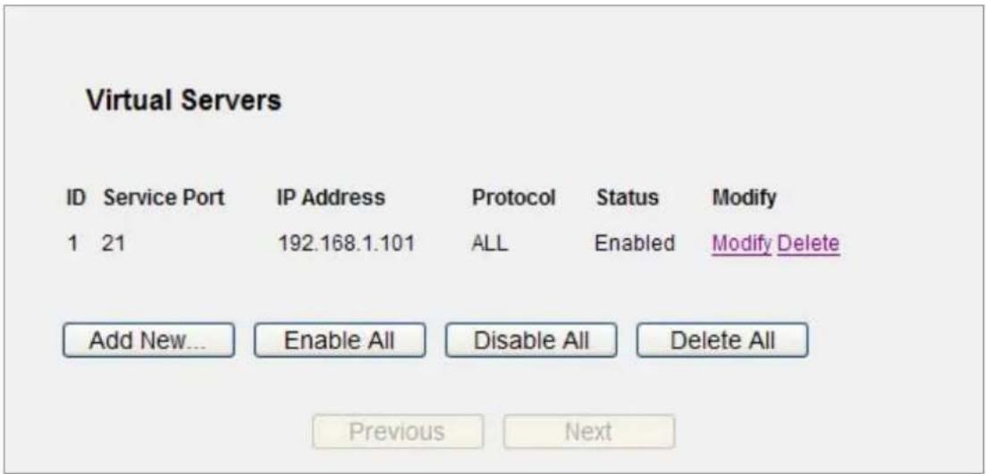
Figure 5-38 Virtual Servers
The page includes the following fields:
| Object Description | |
| Service Port | The numbers of External Ports. You can type a service port or a range of |
| service ports (in XXX – YYY format, XXX is the start port number, YYY is the end port number). | |
| IP Address | The IP Address of the PC providing the service application. |
| Protocol | The protocol used for this application, either TCP, UDP, or All (all protocols supported by the Router). |
| Status | The status of this entry either Enabled or Disabled. |
To setup a virtual server entry:
Step 1. Click the Add New... button.
Step 2. Select the service you want to use from the Common Service Port list. If the Common Service Port list does not have the service that you want to use, type the number of the service port or service port range in the Service Port box.
Step 3. Type the IP Address of the computer in the IP Address box.
Step 4. Select the protocol used for this application, either TCP or UDP, or All.
Step 5. Select the Enable check box to enable the virtual server.
Step 6. Click the Save button.
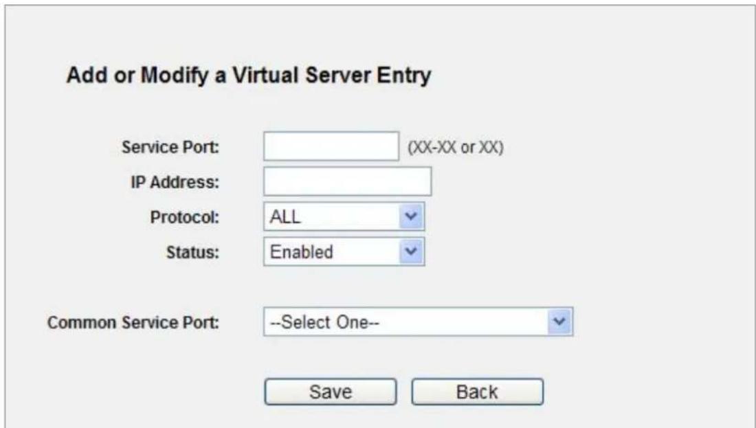
Figure 5-39 Add or Modify a Virtual Server Entry

If your computer or server has more than one type of available service, please select another service, and enter the same IP Address for that computer or server.
To modify or delete an existing entry:
Step 1. Click the Modify in the entry you want to modify. If you want to delete the entry, click the Delete.
Step 2. Modify the information.
Step 3. Click the Save button.
Click the Enable/ Disabled All button to make all entries enabled/ disabled.
Click the Delete All button to delete all entries.
Click the Next button to go to the next page and click the Previous button to return the previous page.

If you set the service port of the virtual server as 80, you must set the Web management port on System Tools -> Remote Management page to be any other value except 80 such as 8080. Otherwise there will be a conflict to disable the virtual server.
5.10.2 Port Triggering
Choose menu "Forwarding→Port Triggering", and you can view and add port triggering in the next screen (shown in Figure 5-40). Some applications require multiple connections, like Internet games, video conferencing, Internet calling and so on. These applications cannot work with a pure NAT Router. Port Triggering is used for some of these applications that can work with an NAT Router.
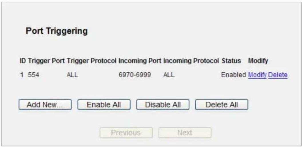
Figure 5-40 Port Triggering
Once the Router is configured, the operation is as follows:
- A local host makes an outgoing connection using a destination port number defined in the Trigger Port field.
- The Router records this connection, opens the incoming port or ports associated with this entry in the Port Triggering table, and associates them with the local host.
- When necessary the external host will be able to connect to the local host using one of the ports defined in the Incoming Ports field.
The page includes the following fields:
| Object Description | |
| Trigger Port | The port for outgoing traffic. An outgoing connection using this port will "Trigger" this rule. |
| Trigger Protocol | The protocol used for Trigger Ports, either TCP, UDP, or All (all protocols supported by the Router). |
| Incoming Ports Range | The port or port range used by the remote system when it responds to the outgoing request. A response using one of these ports will be forwarded to the PC that triggered this rule. You can input at most 5 groups of ports (or port section). Every group of ports must be set apart with ",". For example,2000-2038, 2050-2051, 2085, 3010-3030. |
| Incoming Protocol | The protocol used for Incoming Ports Range, either TCP or UDP, or ALL (all protocols supported by the Router). |
| Status | The status of this entry either Enabled or Disabled. |
To add a new rule, follow the steps below.
Step 1. Click the Add New... button, the next screen will pop up as shown in Figure 5-41.
Step 2. Select a common application from the Common Applications drop-down list, then the Trigger Port field and the Incoming Ports field will be automatically filled. If the Common Applications do not have the application you need, enter the Trigger Port and the Incoming Ports manually.
Step 3. Select the protocol used for Trigger Port from the Trigger Protocol drop-down list, either TCP, UDP, or All.
Step 4. Select the protocol used for Incoming Ports from the Incoming Protocol drop-down list, either TCP or UDP, or All.
Step 5. Select Enable in Status field.
Step 6. Click the Save button to save the new rule.
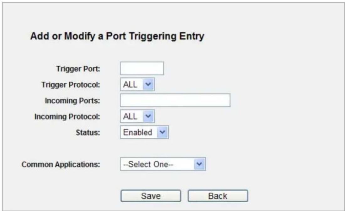
Figure 5-41 Add or Modify a Triggering Entry
To modify or delete an existing entry:
-
Click the Modify in the entry you want to modify. If you want to delete the entry, click the Delete.
-
Modify the information.
-
Click the Save button.
Click the Enable All button to make all entries enabled
Click the Disabled All button to make all entries disabled.
Click the Delete All button to delete all entries

1) When the trigger connection is released, the related opening ports will be closed.
2) Each rule is allowed to be used only by one host on LAN synchronously. The trigger connection of other hosts on LAN will be refused.
3) Incoming Port Range cannot overlap each other.
5.10.3 DMZ
Choose menu "Forwarding→DMZ", and you can view and configure DMZ host in the screen (shown in Figure 5-42). The DMZ host feature allows one local host to be exposed to the Internet for a special-purpose service such as Internet gaming or videoconferencing. DMZ host forwards all the ports at the same time. Any PC whose port is being forwarded must have its DHCP client function disabled and should have a new static IP Address assigned to it because its IP Address may be changed when using the DHCP function.
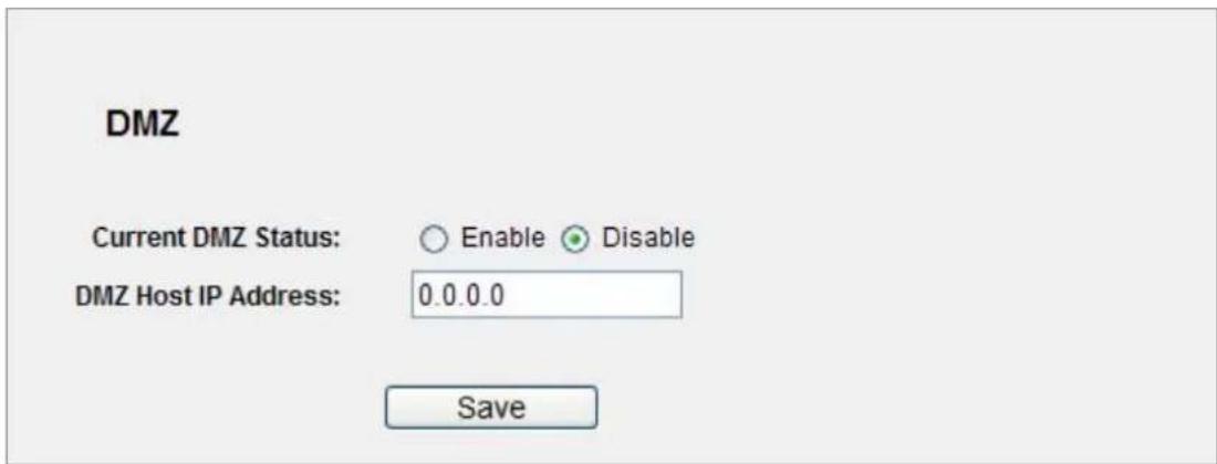
Figure 5-42 DMZ
To assign a computer or server to be a DMZ server:
Step 1. Click the Enable radio button
Step 2. Enter the local host IP Address in the DMZ Host IP Address field
Step 3. Click the Save button.

After you set the DMZ host, the firewall related to the host will not work.
5.10.4 UPnP
Choose menu "Forwarding→UPnP", and you can view the information about UPnP(Universal Plug and Play) in the screen (shown in Figure 5-43). The UPnP feature allows the devices, such as Internet computers, to access the local host resources or devices as needed. UPnP devices can be automatically discovered by the UPnP service application on the LAN.
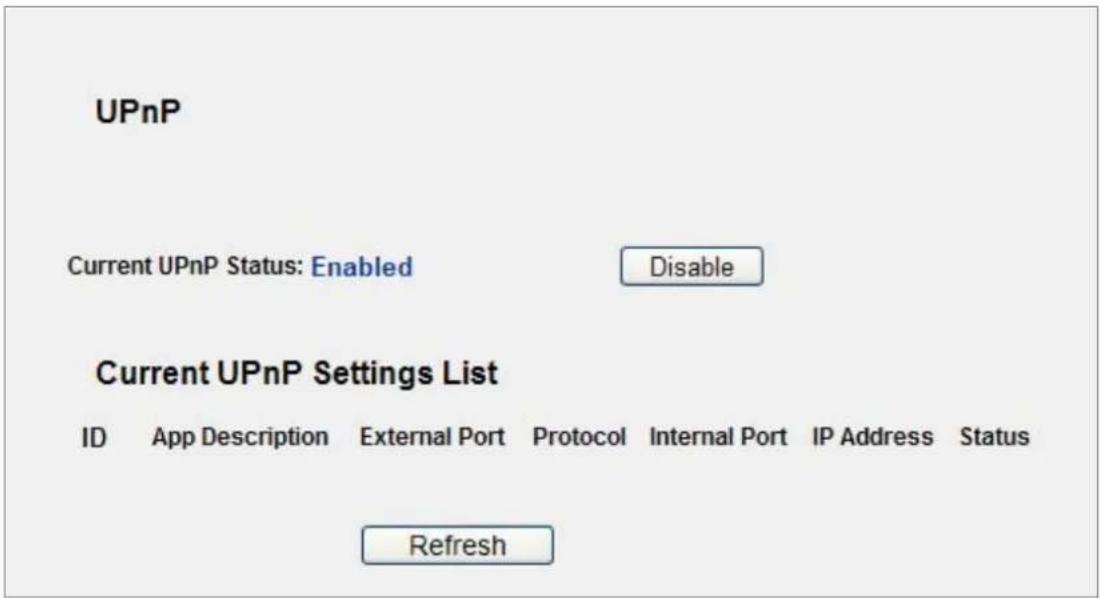
Figure 5-43 UPnP Setting
The page includes the following fields:
| Object Description | |
| Current UPnP Status | UPnP can be enabled or disabled by clicking the Enable or Disable button. As allowing this may present a risk to security, this feature is enabled by default. |
| Current UPnP Settings List | This table displays the current UPnP information.App Description -The description provided by the application in the UPnP requestExternal Port - External port, which the router opened for the application.Protocol - Shows which type of protocol is opened.Internal Port - Internal port, which the router opened for local host.IP Address - The UPnP device that is currently accessing the router.Status - The port's status displayed here. “Enabled” means that port is still active. Otherwise, the port is inactive. |
Click Refresh to update the Current UPnP Settings List.
5.11 Security
There are four submenus under the Security menu as shown in Figure 5-44: Basic Security, Advanced Security, Local Management and Remote Management. Click any of them, and you will be able to configure the corresponding function.
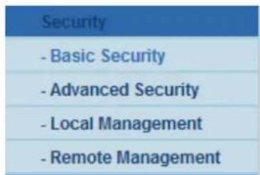
Figure 5-44 The Security menu
5.11.1 Basic Security
Choose menu "Security → Basic Security", and you can configure the basic security in the next screen.
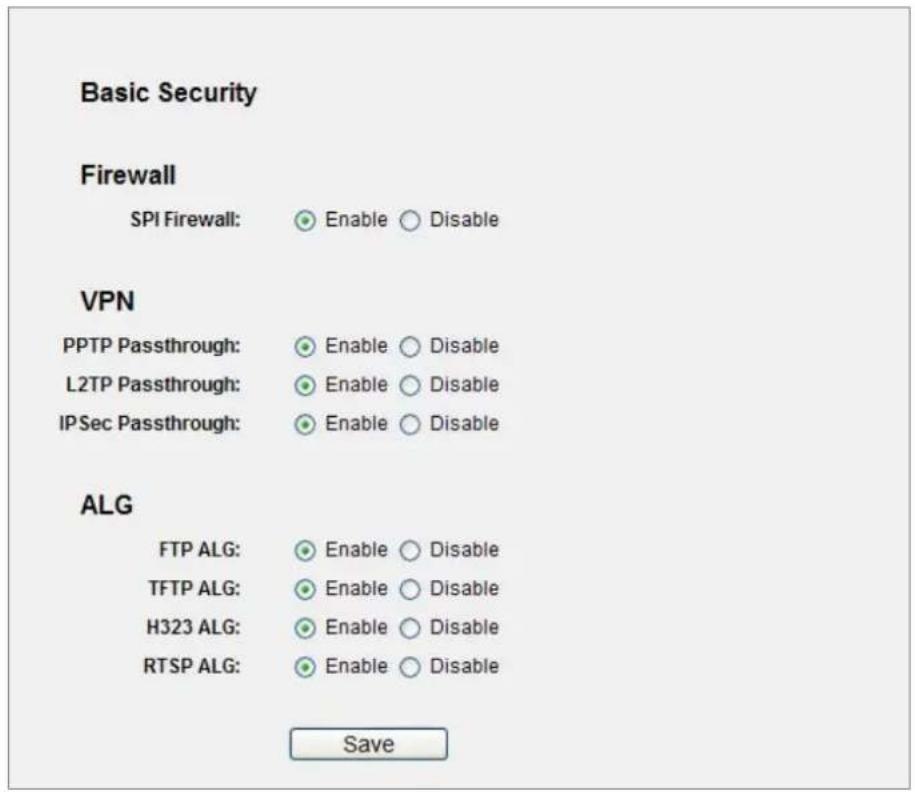
Figure 5-45 Basic Security
The page includes the following fields:
| Object Description | |
| Firewall | A firewall protects your network from the outside world. Here you can enable or disable the Router's firewall.SPI Firewall - SPI (Stateful Packet Inspection, also known as dynamic packet filtering) helps to prevent cyber attacks by tracking more state per session. It validates that the traffic passing through the session conforms to the protocol. SPI Firewall is enabled by factory default. If you want all the computers on the LAN exposed to the outside world, you can disable it. |
| VPN | VPN Passthrough must be enabled if you want to allow VPN tunnels using IPSec, PPTP, or L2TP protocols to pass through the Router's firewall.PPTP Passthrough - Point-to-Point Tunneling Protocol (PPTP) allows the Point-to-Point Protocol (PPP) to be tunneled through an IP network. To allow PPTP tunnels to pass through theRouter, keep the default, Enabled.L2TP Passthrough - Layer 2 Tunneling Protocol (L2TP) is the method used to enable Point-to-Point sessions via the Internet on the Layer 2 level. To allow L2TP tunnels to pass through the Router, keep the default, Enabled.IPSec Passthrough - Internet Protocol Security (IPSec) is a suite of protocols for ensuring private, secure communications over Internet Protocol (IP) networks, through the use of cryptographic security services. To allow IPSec tunnels to pass through the Router, keep the default, Enabled. |
| ALG | It is recommended to enable Application Layer Gateway (ALG) because ALG allows customized Network Address Translation (NAT) traversal filters to be plugged into the gateway to support address and port translation for certain application layer "control/data" protocols such as FTP, TFTP, H323 etc.FTP ALG - To allow FTP clients and servers to transfer data across NAT, keep the default Enable.TFTP ALG - To allow TFTP clients and servers to transfer data across NAT, keep the default Enable.H323 ALG - To allow Microsoft NetMeeting clients to communicate across NAT, keep the default Enable. |
Click the Save button to save your settings.
5.11.2 Advanced Security
Choose menu “Security → Advanced Security”, you can protect the Router from being attacked by TCP-SYN Flood, UDP Flood and ICMP-Flood in the screen as shown in Figure 5-46.
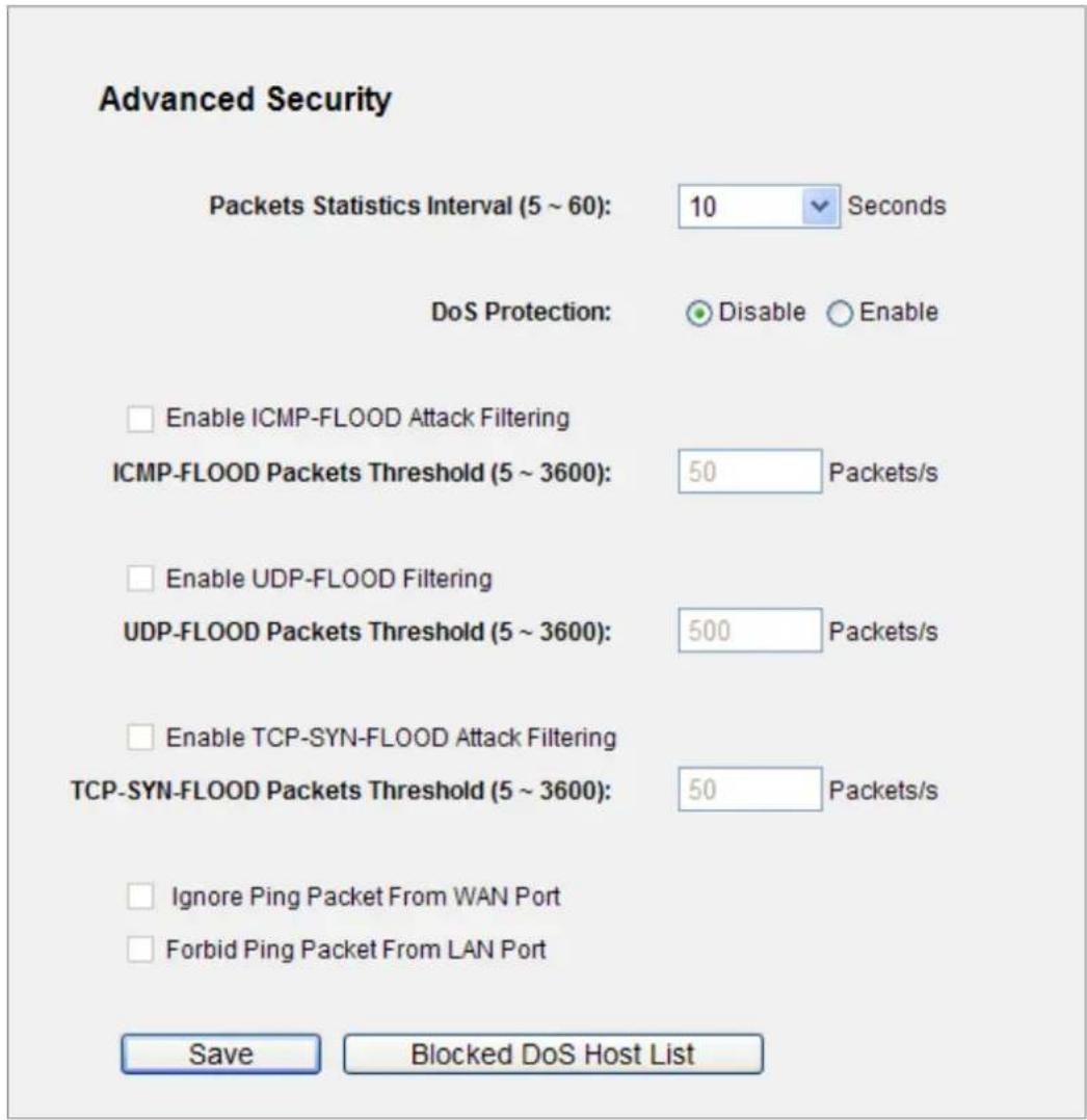
Figure 5-46 Advanced Security
The page includes the following fields:
| Object Description | |
| Packets Statistics Interval (5~60) | The default value is 10. Select a value between 5 and 60 seconds from the drop-down list. The Packets Statistics Interval value indicates the time section of the packets statistics. The result of the statistics is used for analysis by SYN Flood, UDP Flood and ICMP-Flood. |
| DoS Protection | Denial of Service protection. Check the Enable or Disable button to enable or disable the DoS protection function. Only when it is enabled, will the flood filters be enabled. |
| Enable ICMP-FLOOD Attack Filtering | Enable or Disable the ICMP-FLOOD Attack Filtering. |
| ICMP-FLOOD Packets | The default value is 50. Enter a value between 5 ~ 3600. When the current ICMP-FLOOD Packets number is beyond the set value, the |
| Threshold (5~3600) | Router will startup the blocking function immediately. |
| Enable UDP-FLOOD Filtering | Enable or Disable the UDP-FLOOD Filtering. |
| UDP-FLOOD Packets Threshold (5~3600) | The default value is 500. Enter a value between 5 ~ 3600. When the current UPD-FLOOD Packets number is beyond the set value, the Router will startup the blocking function immediately. |
| Enable TCP-SYN-FLOOD Attack Filtering | Enable or Disable the TCP-SYN-FLOOD Attack Filtering. |
| TCP-SYN-FLOOD Packets Threshold (5~3600) | The default value is 50. Enter a value between 5 ~ 3600. When the current TCP-SYN-FLOOD Packets numbers is beyond the set value, the Router will startup the blocking function immediately. |
| Ignore Ping Packet From WAN Port | Enable or Disable Ignore Ping Packet From WAN Port. The default setting is disabled. If enabled, the ping packet from the Internet cannot access the Router. |
| Forbid Ping Packet From LAN Port | Enable or Disable Forbid Ping Packet From LAN Port. The default setting is disabled. If enabled, the ping packet from LAN cannot access the Router. This function can be used to defend against some viruses. |
Click the Save button to save the settings.
Click the Blocked DoS Host List button to display the DoS host table by blocking.

DoSProtection will take effect only when the Traffic Statistics in "System Tool → Traffic Statistics" is enabled.
5.11.3 Local Management
Choose menu "Security → Local Management", and you can configure the management rule in the screen as shown in Figure 5-47. The management feature allows you to deny computers in LAN from accessing the Router.
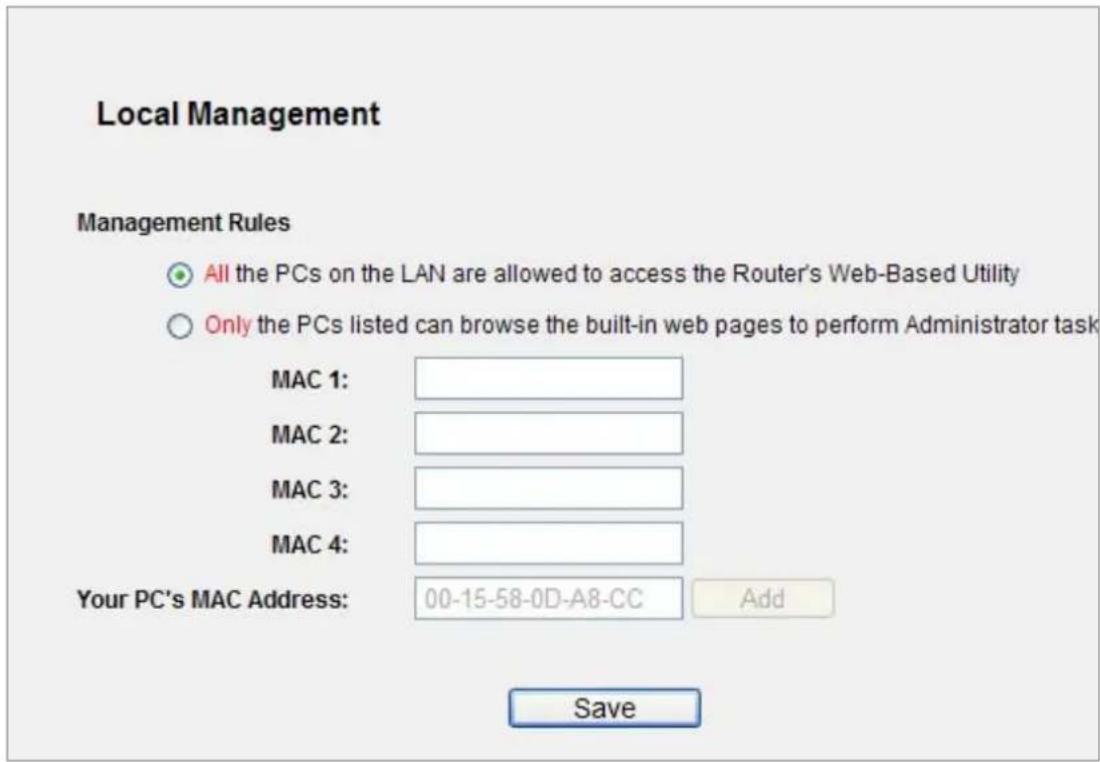
Figure 5-47 Local Management
By default, the radio button "All the PCs on the LAN are allowed to access the Router's Web-Based Utility" is checked. If you want to allow PCs with specific MAC Addresses to access the Setup page of the Router's Web-Based Utility locally from inside the network, check the radio button "Only the PCs listed can browse the built-in web pages to perform Administrator tasks", and then enter each MAC Address in a separate field. The format for the MAC Address is XX-XX-XX-XX-XX-XX (X is any hexadecimal digit). Only the PCs with MAC address listed can use the password to browse the built-in web pages to perform Administrator tasks while all the others will be blocked.
After click the Add button, your PC's MAC Address will be placed in the list above.
Click the Save button to save your settings.

If your PC is blocked but you want to access the Router again, use a pin to press and hold the Reset Button (hole) on the back panel for about 5 seconds to reset the Router's factory defaults on the Router's Web-Based Utility.
5.11.4 Remote Management
Choose menu "Security → Remote Management", and you can configure the Remote Management function in the screen as shown in Figure 5-48. This feature allows you to manage your Router from a remote location via the Internet.
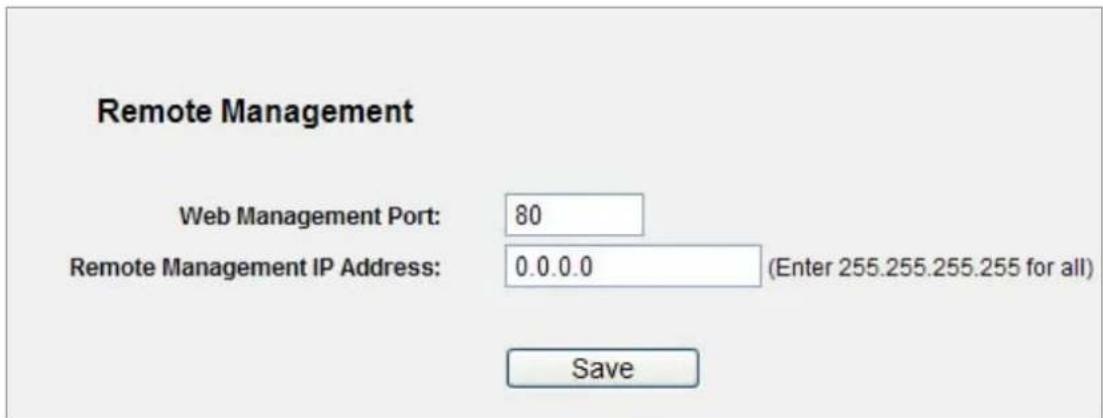
Figure 5-48 Remote Management
The page includes the following fields:
| Object Description | |
| Web Management Port | Web browser access normally uses the standard HTTP service port 80. This Router's default remote management web port number is 80. For greater security, you can change the remote management web port to a custom port by entering that number in the box provided. Choose a number between 1 and 65534 but do not use the number of any common service port. |
| Remote Management IP Address | This is the current address you will use when accessing your Router from the Internet. This function is disabled when the IP address is set to the default value of 0.0.0.0. To enable this function change 0.0.0.0 to a valid IP address. If set to 255.255.255.255, then all the hosts can access the Router from internet. |

To access the Router, you should type your Router's WAN IP address into your browser's address (in IE) or Location (in Navigator) box, followed by a colon and the custom port number. For example, if your Router's WAN address is 210.66.155.14, and the port number used is 8080, please enter http://210.66.155.14:8080 in your browser. Later, you may be asked for the Router's password. After successfully entering the username and password, you will be able to access the Router's web-based utility.
Be sure to change the Router's default password to a very secure password.
5.12 Parental Control
Choose menu "Parental Control", and you can configure the parental control in the screen as shown in Figure 5-49. The Parental Control function can be used to control the internet activities of the child, limit the child to access certain websites and restrict the time of surfing.
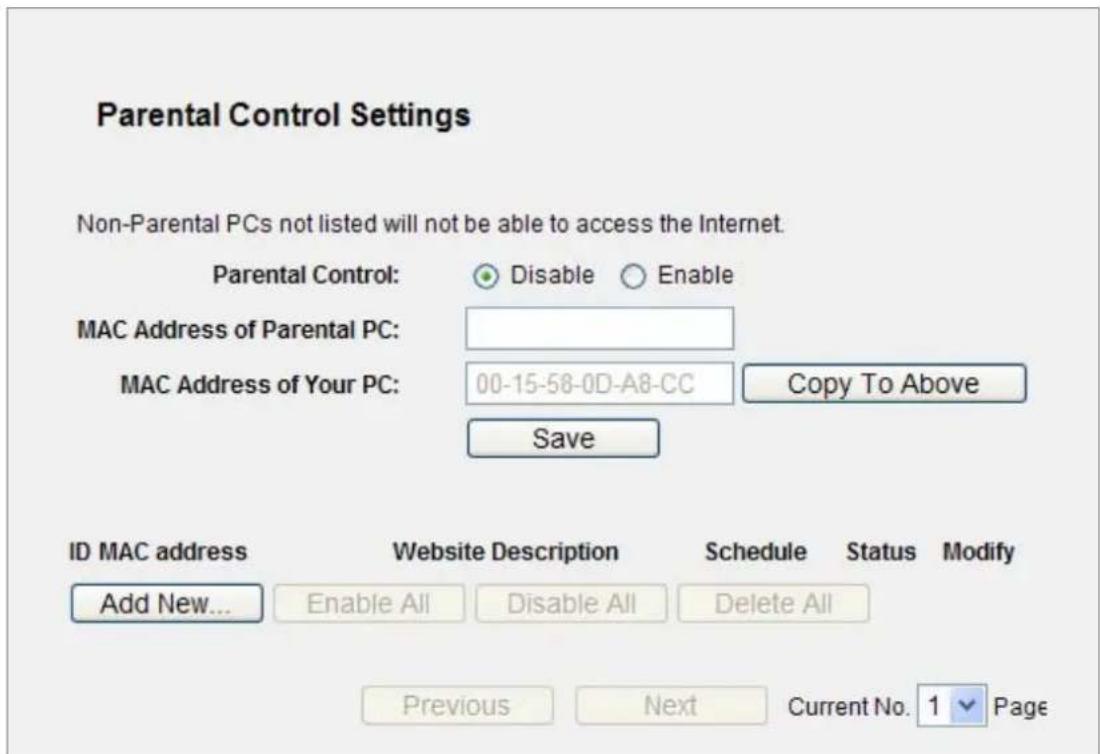
Figure 5-49 Parental Control Settings
The page includes the following fields:
| Object Description | |
| Parental Control | Check Enable if you want this function to take effect, otherwise check Disable. |
| MAC Address of Parental PC | In this field, enter the MAC address of the controlling PC, or you can make use of the Copy To Above button below. |
| MAC Address of Your PC | This field displays the MAC address of the PC that is managing this Router. If the MAC Address of your adapter is registered, you can click the Copy To Above button to fill this address to the MAC Address of Parental PC field above. |
| Website Description | Description of the allowed website for the PC controlled. |
| Schedule | The time period allowed for the PC controlled to access the Internet.For detailed information, please go to “Access Control → Schedule”. |
| Modify | Here you can edit or delete an existing entry. |
To add a new entry, please follow the steps below.
Step 1. Click the Add New... button and the next screen will pop-up as shown in Figure 5-49.
Step 2. Enter the MAC address of the PC (e.g. 00-11-22-33-44-AA) you'd like to control in the MAC Address of Child PC field. Or you can choose the MAC address from the All Address in Current LAN drop-down list.
Step 3. Give a description (e.g. Allow Google) for the website allowed to be accessed in the Website Description field.
Step 4. Enter the allowed domain name of the website, either the full name or the keywords (e.g. google) in the Allowed Domain Name field. Any domain name with keywords in it (www.google.com, www.google.com.tw) will be allowed.
Step 5. Select from the Effective Time drop-down list the schedule (e.g. Schedule_1) you want the entry to take effect. If there are not suitable schedules for you, click the Schedule in red below to go to the Advance Schedule Settings page and create the schedule you need.
Step 6. In the Status field, you can select Enabled or Disabled to enable or disable your entry.
Step 7. Click the Save button.
Click the Enable All button to enable all the rules in the list.
Click the Disable All button to disable all the rules in the list.
Click the Delete All button to delete all the entries in the table.
Click the Next button to go to the next page, or click the Previous button return to the previous page.
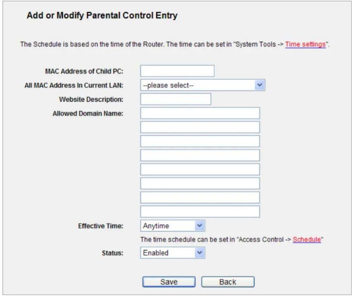
Figure 5-50 Add or Modify Parental Control Entry
For example: If you desire that the child PC with MAC address 00-11-22-33-44-AA can access www.google.com on Saturday only while the parent PC with MAC address 00-11-22-33-44-BB is without any restriction, you should follow the settings below.
Step 1. Click "Parental Control" menu on the left to enter the Parental Control Settings page. Check Enable and enter the MAC address 00-11-22-33-44-BB in the MAC Address of Parental PC field. Then click Save button.
Step 2. Click "Access Control → Schedule" on the left to enter the Schedule Settings page. Click Add New... button to create a new schedule with Schedule Description is Schedule_1, Day is Sat and Time is all day-24 hours. Then click Save button.
Step 3. Click "Parental Control" menu on the left to go back to the Add or Modify Parental Control Entry page:
- Click Add New... button.
Enter 00-11-22-33-44-AA in the MAC Address of Child PC field.
Enter "Allow Google" in the Website Description field.
Enter "www.google.com" in the Allowed Domain Name field.
Select "Schedule_1" you create just now from the Effective Time drop-down list.
In Status field, select Enable.
Step 4. Click Save to complete the settings.
Then you will go back to the Parental Control Settings page and see the following list, as shown in Figure 5-51.
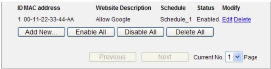
Figure 5-51 Parental Control Settings
5.13 Access Control
There are four submenus under the Access Control menu as shown in Figure 5-52: Rule, Host, Target and Schedule. Click any of them, and you will be able to configure the corresponding function.
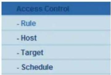
Figure 5-52 Access Control
5.13.1 Rule
Choose menu "Access Control → Rule", and you can view and set Access Control rules in the screen as shown in Figure 5-53.
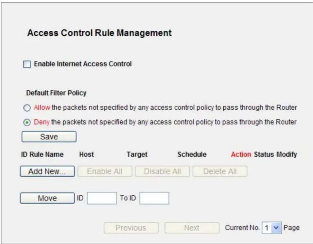
Figure 5-53 Access Control Rule Management
The page includes the following fields:
| Object Description | |
| Enable Internet Access Control | Select the check box to enable the Internet Access Control function, so the Default Filter Policy can take effect. |
| Rule Name | Here displays the name of the rule and this name is unique. |
| Host | Here displays the host selected in the corresponding rule. |
| Target | Here displays the target selected in the corresponding rule. |
| Schedule | Here displays the schedule selected in the corresponding rule. |
| Action | Here displays the action the Router takes to deal with the packets. It could be Allow or Deny. Allow means that the Router permits the packets to go through the Router. Deny means that the Router rejects the packets to go through the Router. |
| Status | This field displays the status of the rule. Enabled means the rule will take effect, Disabled means the rule will not take effect. |
| Modify | Here you can edit or delete an existing rule. |
To add a new rule, please follow the steps below.
Step 1. Click the Add New... button and the next screen will pop-up as shown in Figure 5-53.
Step 2. Give a name (e.g. Rule_1) for the rule in the Rule Name field.
Step 3. Select a host from the Host drop-down list or choose "Click Here To Add New Host List".
Step 4. Select a target from the Target drop-sown list or choose "Click Here To Add New Target List".
Step 5. Select a schedule from the Schedule drop-down list or choose "Click Here To Add New Schedule".
Step 6. In the Action field, select Deny or Allow.
Step 7. In the Status field, select Enabled or Disabled to enable or disable your entry.
Step 8. Click the Save button.
Click the Enable All button to enable all the rules in the list.
Click the Disable All button to disable all the rules in the list.
Click the Delete All button to delete all the entries in the table.
You can change the entry's order as desired. Fore entries are before hind entries. Enter the ID number
in the first box you want to move and another ID number in second box you want to move to, and then click the Move button to change the entry's order.
Click the Next button to go to the next page, or click the Previous button return to the previous page.
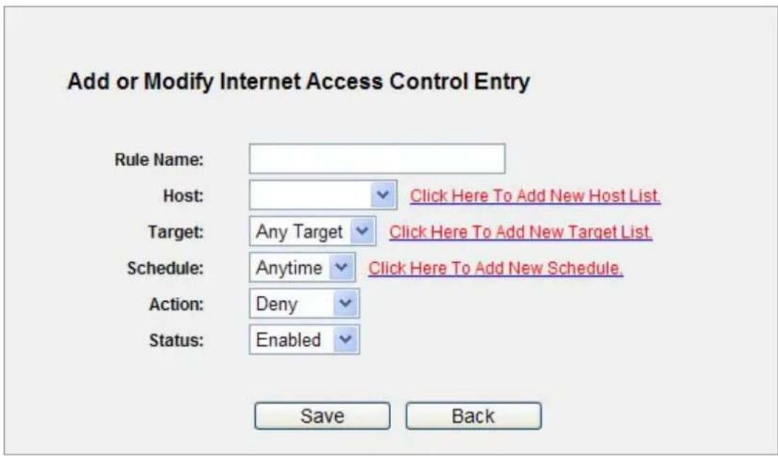
Figure 5-54 Add or Modify Internet Access Control Entry
For example: If you desire to allow the host with MAC address 00-11-22-33-44-AA to access www.google.com only from 18:00 to 20:00 on Saturday and Sunday, and forbid other hosts in the LAN to access the Internet, you should follow the settings below:
Step 1. Click "Access Control → Host" in the left to enter the Host Settings page. Add a new entry with the Host Description is Host_1 and MAC Address is 00-11-22-33-44-AA.
Step 2. Click "Access Control → Target" in the left to enter the Target Settings page. Add a new entry with the Target Description is Target_1 and Domain Name is www.google.com.
Step 3. Click "Access Control Schedule" in the left to enter the Schedule Settings page. Add a new entry with the Schedule Description is Schedule_1, Day is Sat and Sun, Start Time is 1800 and Stop Time is 2000.
Step 4. Click "Access Control → Rule" in the left to return to the Access Control Rule Management page. Select "Enable Internet Access Control" and choose "Deny the packets not specified by any access control policy to pass through the Router".
Step 5. Click Add New... button to add a new rule as follows:
In Rule Name field, create a name for the rule. Note that this name should be unique, for example Rule_1.
In Host field, select Host_1.
In Target field, select Target_1.
In Schedule field, select Schedule_1.
In Action field, select Allow.
In Status field, select Enable.
Click Save to complete the settings.
Then you will go back to the Access Control Rule Management page and see the following list.
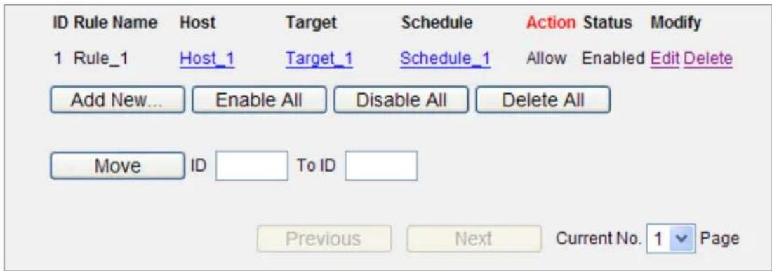
Figure 5-55 Access Control Rule list
5.13.2 Host
Choose menu "Access Control → Host", and you can view and set a Host list in the screen as shown in Figure 5-56. The host list is necessary for the Access Control Rule.
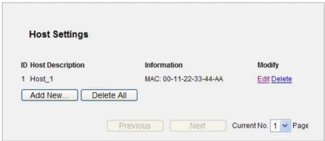
Figure 5-56 Access Control host Settings
The page includes the following fields:
| Object Description | |
| Host Description | Here displays the description of the host and this description is unique. |
| Information | Here displays the information about the host. It can be IP or MAC. |
| Modify | To modify or delete an existing entry. |
To add a new entry, please follow the steps below.
Step 1. Click the Add New... button.
Step 2. In the Mode field, select IP Address or MAC Address.
If you select IP Address, the screen shown is Figure 5-57.
1) In Host Description field, create a unique description for the host (e.g. Host_1).
2) In LAN IP Address field, enter the IP address.
If you select MAC Address, the screen shown is Figure 5-58.
1) In Host Description field, create a unique description for the host (e.g. Host_1).
2) In MAC Address field, enter the MAC address.
Step 3. Click the Save button to complete the settings.
Click the Delete All button to delete all the entries in the table.
Click the Next button to go to the next page, or click the Previous button return to the previous page.
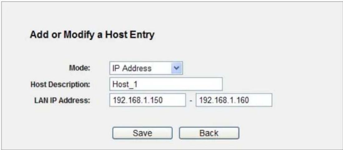
Figure 5-57 Add or Modify a Host Entry – IP Mode
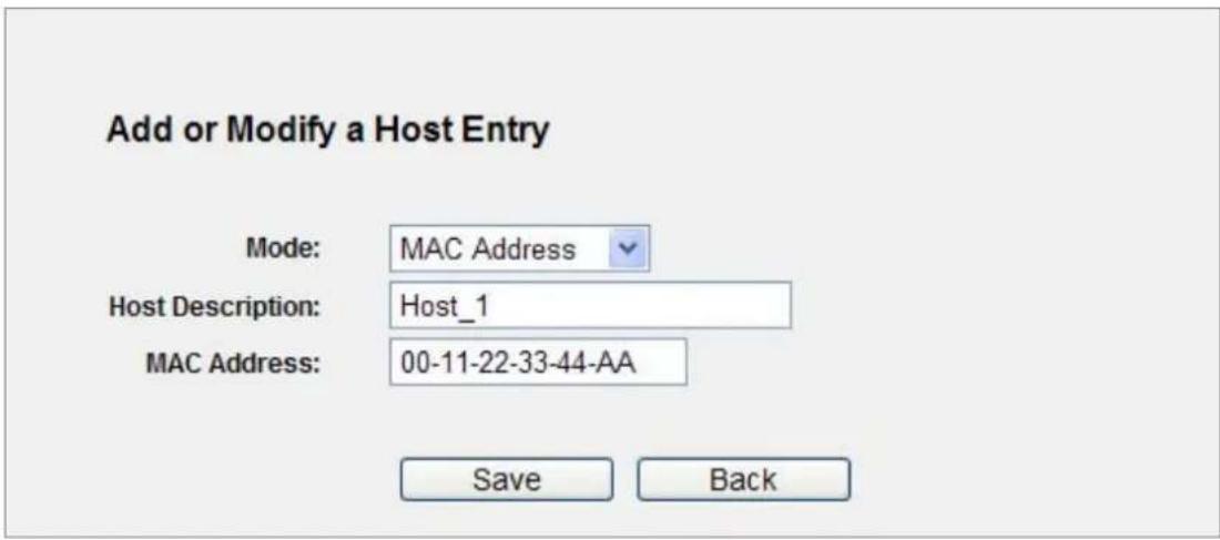
Figure 5-58 Add or Modify a Host Entry – MAC Address Mode
For example: If you desire to restrict the internet activities of host with MAC address 00-11-22-33-44-AA, you should first follow the settings below:
Step 1. Click Add New... button in Figure 5-59 to enter the Add or Modify a Host Entry page.
Step 2. In Mode field, select MAC Address from the drop-down list.
Step 3. In Host Description field, create a unique description for the host (e.g. Host_1).
Step 4. In MAC Address field, enter 00-11-22-33-44-AA.
Step 5. Click Save to complete the settings.
Then you will go back to the Host Settings page and see the following list.
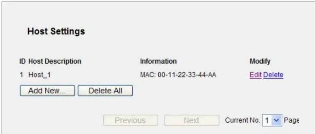
Figure 5-59 Host Settings List
5.13.3 Target
Choose menu "Access Control → Target", and you can view and set a Target list in the screen as shown in Figure 5-60. The target list is necessary for the Access Control Rule.
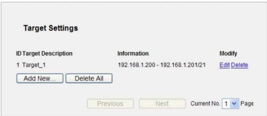
Figure 5-60 Target Settings
The page includes the following fields:
| Object Description | |
| Target Description | Here displays the description about the target and this description is unique. |
| Information | The target can be IP address, port, or domain name. |
| Modify | To modify or delete an existing entry. |
To add a new entry, please follow the steps below.
Step 1. Click the Add New... button.
Step 2. In Mode field, select IP Address or Domain Name.
If you select IP Address, the screen shown is Figure 5-61.
- In Target Description field, create a unique description for the target (e.g. Target_1).
- In IP Address field, enter the IP address of the target.
- Select a common service from Common Service Port drop-down list, so that the Target Port will be automatically filled. If the Common Service Port drop-down list doesn't have the service you want, specify the Target Port manually.
- In Protocol field, select TCP, UDP, ICMP or ALL.
If you select Domain Name, the screen shown is Figure 5-62.
2) In Target Description field, create a unique description for the target (e.g. Target_1).
3) In Domain Name field, enter the domain name, either the full name or the keywords (for example google) in the blank. Any domain name with keywords in it (www.google.com, www.google.tw) will be blocked or allowed. You can enter 4 domain names.
Step 3. Click the Save button.
Click the Delete All button to delete all the entries in the table.
Click the Next button to go to the next page, or click the Previous button return to the previous page.
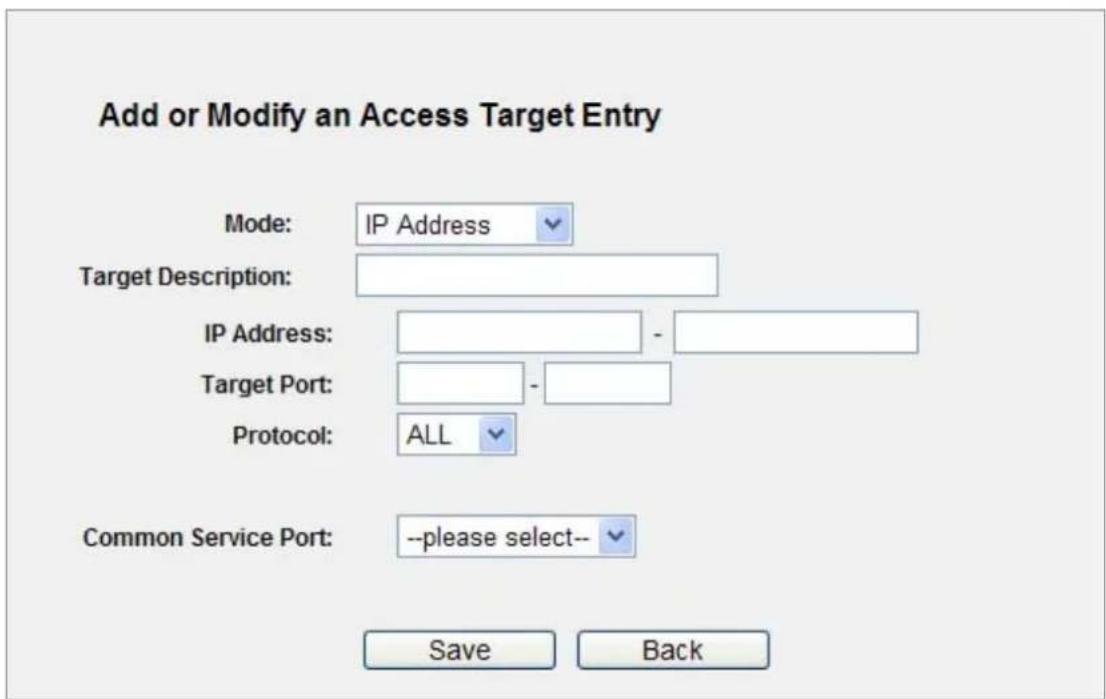
Figure 5-61 Add or Modify an Access Target Entry
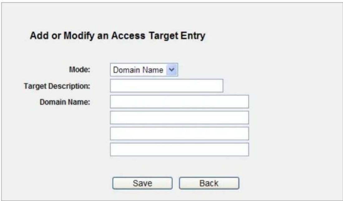
Figure 5-62 Add or Modify an Access Target Entry
For example: If you desire to restrict the internet activities of host with MAC address 00-11-22-33-44-AA in the LAN to access www.google.com only, you should first follow the settings below:
Step 1. Click Add New... button in Figure 5-63 to enter the Add or Modify an Access Target Entry page.
Step 2. In Mode field, select Domain Name from the drop-down list.
Step 3. In Target Description field, create a unique description for the target (e.g. Target_1).
Step 4. In Domain Name field, enter www.google.com.
Step 5. Click Save to complete the settings.
Then you will go back to the Target Settings page and see the following list.
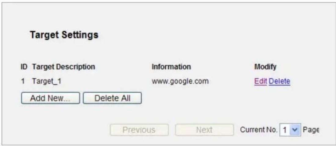
Figure 5-63 Target Settings List
5.13.4 Schedule
Choose menu "Access Control Schedule", and you can view and set a Schedule list in the next screen as shown in Figure 5-64. The Schedule list is necessary for the Access Control Rule.
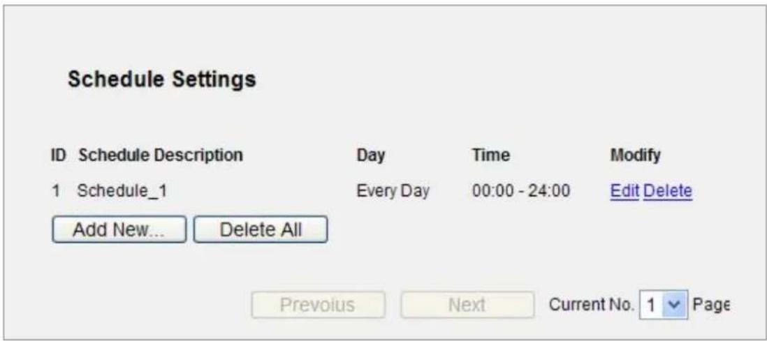
Figure 5-64 Schedule Settings
The page includes the following fields:
| Object Description | |
| Schedule Description | Here displays the description of the schedule and this description is unique. |
| Day | Here displays the day(s) in a week. |
| Time | Here displays the time period in a day. |
| Modify | Here you can edit or delete an existing schedule. |
To add a new schedule, follow the steps below.
Step 1. Click Add New... button shown in Figure 5-64 and the next screen will pop-up as shown in Figure 5-65.
Step 2. In Schedule Description field, create a unique description for the schedule (e.g. Schedule_1).
Step 3. In Day field, select the day or days you need.
Step 4. In Time field, you can select all day-24 hours or you may enter the Start Time and Stop Time in the corresponding field.
Step 5. Click Save to complete the settings.
Click the Delete All button to delete all the entries in the table.
Click the Next button to go to the next page, or click the Previous button return to the previous page.
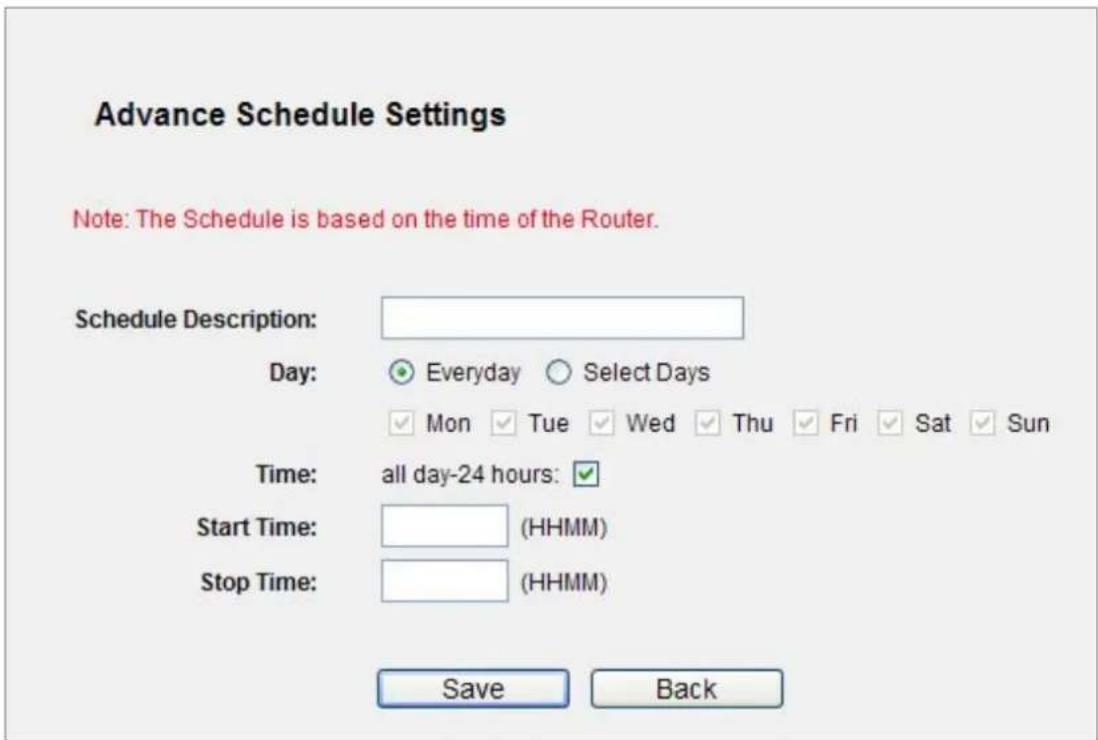
Figure 5-65 Advanced Schedule Settings
For example: If you desire to restrict the internet activities of host with MAC address 00-11-22-33-44-AA to access www.google.com only from 18:00 to 20:00 on Saturday and Sunday, you should first follow the settings below:
Step 1. Click Add New... button shown in Figure 5-66 to enter the Advanced Schedule Settings page.
Step 2. In Schedule Description field, create a unique description for the schedule (e.g. Schedule_1).
Step 3. In Day field, check the Select Days radio button and then select Sat and Sun.
Step 4. In Time field, enter 1800 in Start Time field and 2000 in Stop Time field.
Step 5. Click Save to complete the settings.
Then you will go back to the Schedule Settings page and see the following list.
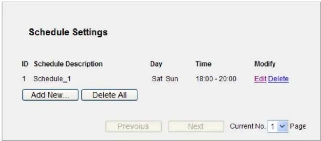
Figure 5-66 Schedule Settings List
5.14 Advanced Routing
There are two submenus under the Advanced Routing menu as shown in Figure 5-67: Static Routing List, System Routing Table. Click any of them, and you will be able to configure the corresponding function.
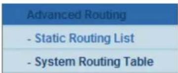
Figure 5-67 Advanced Routing
5.14.1 Static Routing List
Choose menu "Static Routing List", and you can configure the static route in the next screen (shown
in Figure 5-68). A static route is a pre-determined path that network information must travel to reach a specific host or network.
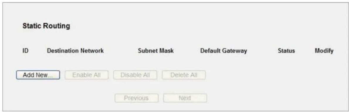
Figure 5-68 Static Routing
To add static routing entries:
Step 1. Click Add New... shown in Figure 5-69, you will see the following screen.
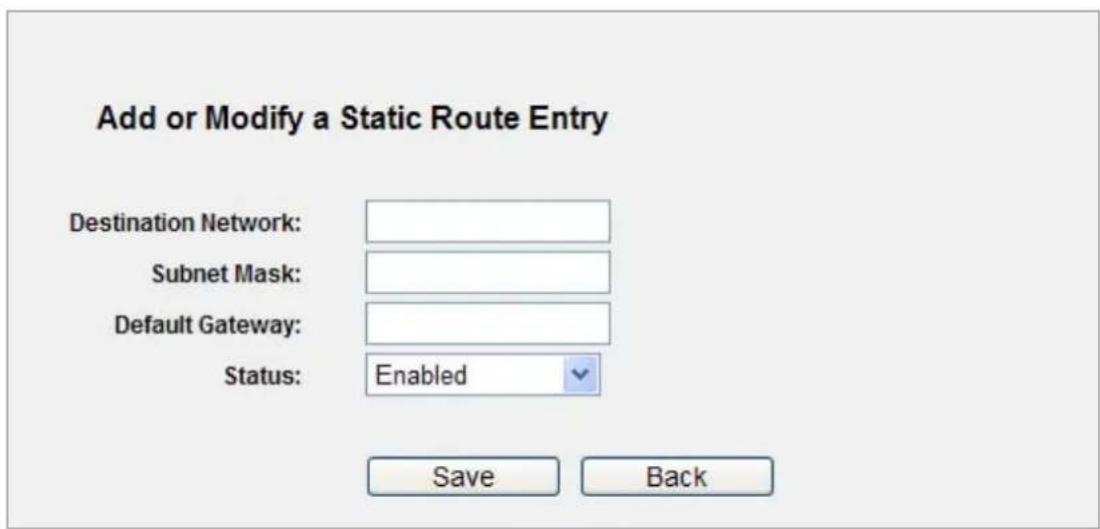
Figure 5-69 Add or Modify a Static Route Entry
Step 2. Enter the following data:
| Object Description | |
| Destination IP Address | The Destination IP Address is the address of the network or host that you want to assign to a static route. |
| Subnet Mask | The Subnet Mask determines which portion of an IP Address is the network portion, and which portion is the host portion. |
| Gateway | This is the IP Address of the gateway device that allows for contact between the Router and the network or host. |
| Status | Select Enabled or Disabled for this entry on the Status pull-down list. |
Step 3. Click the Save button to make the entry take effect.
Other configurations for the entries:
Click the Delete button to delete the entry.
Click the Enable All button to enable all the entries.
Click the Disable All button to disable all the entries.
Click the Delete All button to delete all the entries.
Click the Previous button to view the information in the previous screen, click the Next button to view the information in the next screen.
5.14.2 System Routing Table
Choose menu "System Routing Table", and you can check all of the valid route entries in use. The Destination IP address, Subnet Mask, Gateway, and Interface will be displayed for each entry. Click the Refresh button to refresh the data displayed.
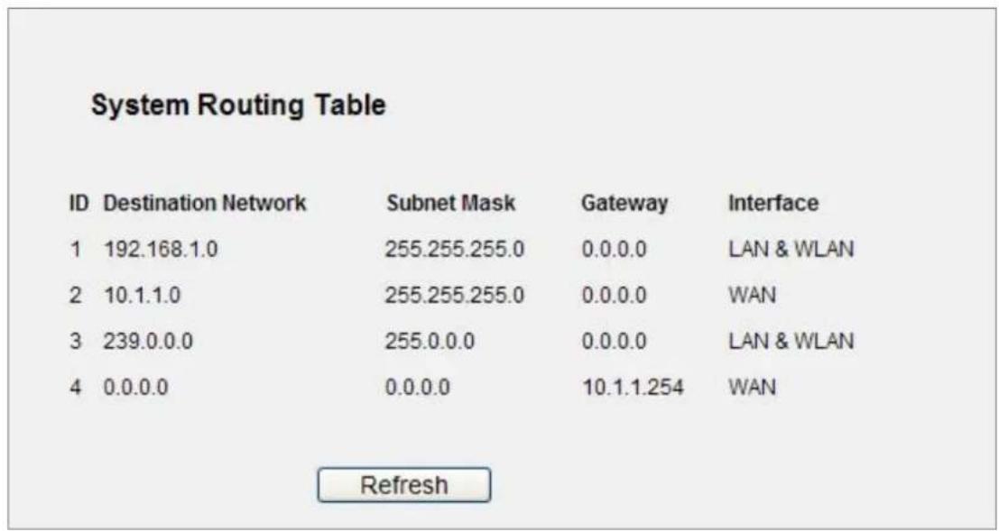
Figure 5-70 System Routing Table
5.15 Bandwidth Control
There are two submenus under the Bandwidth Control menu as shown in Figure 5-71. Click any of them, and you will be able to configure the corresponding function. The detailed explanations for each submenu are provided below.
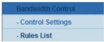
Figure 5-71 Bandwidth Control
5.15.1 Control Settings
Choose menu "Bandwidth Control → Control Settings", you can configure the Egress Bandwidth and Ingress Bandwidth in the next screen. Their values you configure should be less than 100000Kbps. For optimal control of the bandwidth, please select the right Line Type and ask your ISP for the total bandwidth of the egress and ingress.
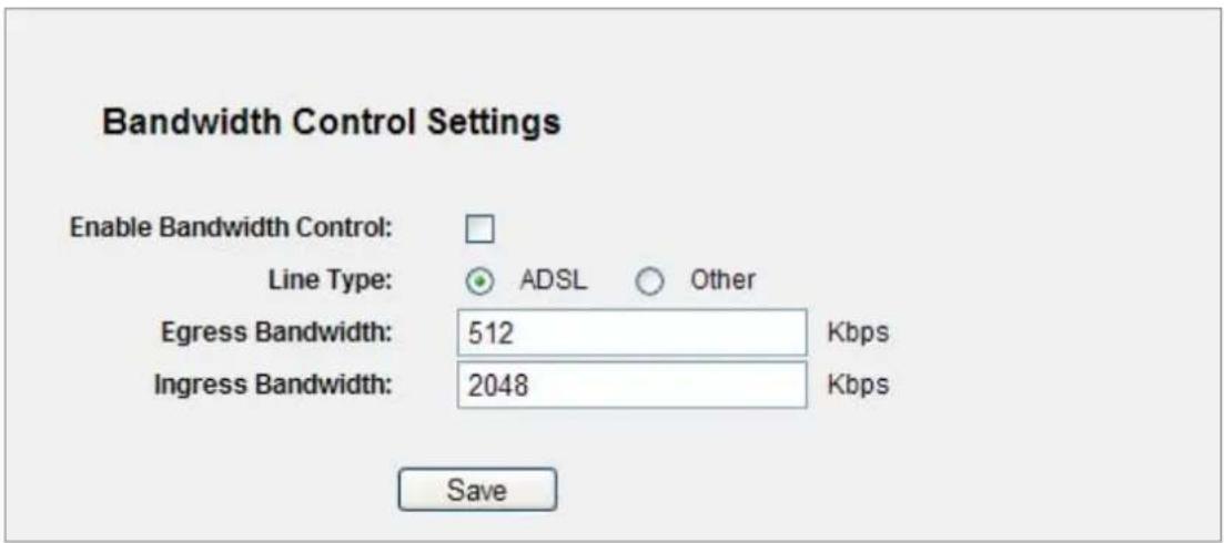
Figure 5-72 Bandwidth Control Settings
The page includes the following fields:
| Object Description | |
| Enable Bandwidth Control | Check this box so that the Bandwidth Control settings can take effect. |
| Line Type | Select the right type for you network connection. If you don’t know how to choose, please ask your ISP for the information. |
| Egress Bandwidth | The upload speed through the WAN port. |
| Ingress Bandwidth | The download speed through the WAN port. |
5.15.2 Rules List
Choose menu "Bandwidth Control → Rules List", you can view and configure the Bandwidth Control rules in the screen below.
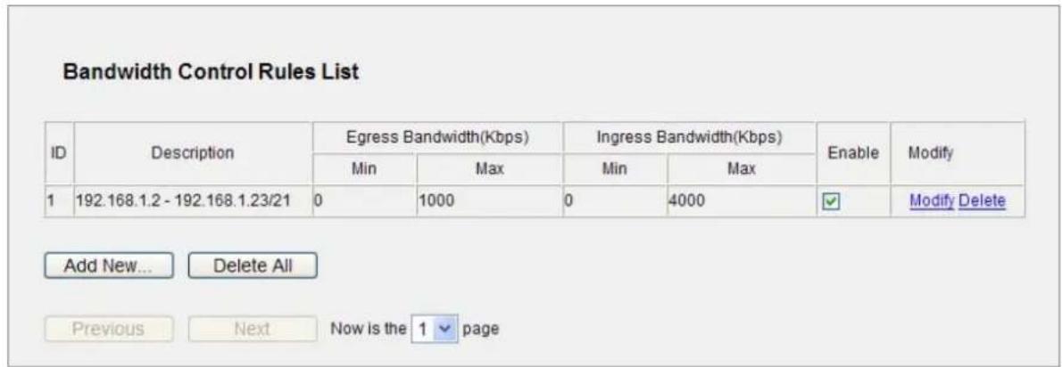
Figure 5-73 Bandwidth Control Rules List
The page includes the following fields:
| Object Description | |
| Description | This is the information about the rules such as address range. |
| Egress bandwidth | This field displays the max and mix upload bandwidth through the WAN port, the default is 0. |
| Ingress bandwidth | This field displays the max and mix download bandwidth through the WAN port, the default is 0. |
| Enable | This displays the status of the rule. |
| Modify | Click Modify to edit the rule. Click Delete to delete the rule. |
To add/modify a Bandwidth Control rule, follow the steps below.
Step 1: Click Add New... shown in Figure 5-73, you will see a new screen shown in Figure 5-74.
Step 2: Enter the information like the screen shown below.
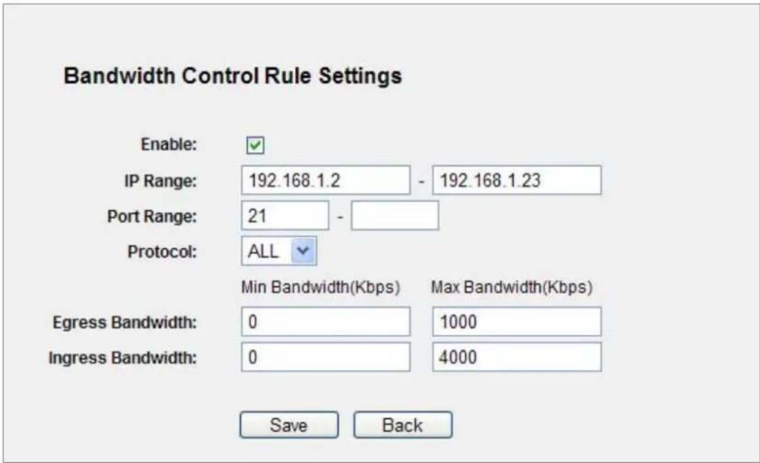
Figure 5-74 Bandwidth Control Rule Settings
Step 3: Click the Save button.
5.16 IP & MAC Binding
There are two submenus under the IP &MAC Binding menu (shown in Figure 5-75): Binding Settings and ARP List. Click any of them, and you will be able to scan or configure the corresponding function. The detailed explanations for each submenu are provided below.
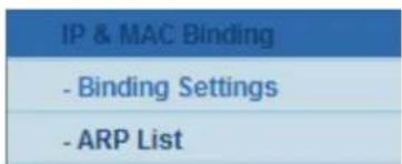
Figure 5-75 the IP & MAC Binding menu
5.16.1 Binding Settings
This page displays the IP & MAC Binding Setting table; you can operate it in accord with your desire. (shown in Figure 5-76).
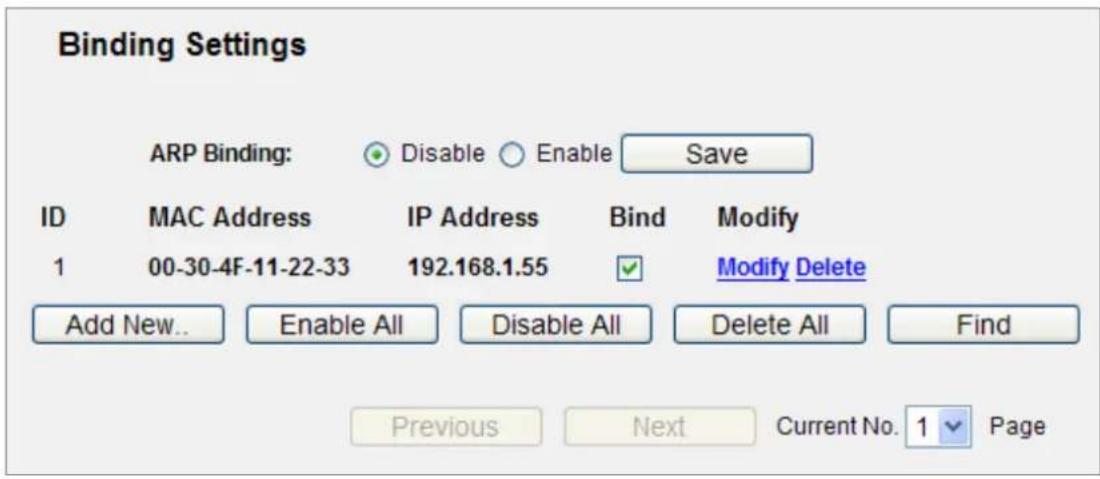
Figure 5-76 Binding Setting
The page includes the following fields:
| Object Description | |
| MAC Address | The MAC address of the controlled computer in the LAN. |
| IP Address | The assigned IP address of the controlled computer in the LAN. |
| Bind | Check this option to enable ARP binding for a specific device. |
| Modify | To modify or delete an existing entry. |
When you want to add or modify an IP & MAC Binding entry, you can click the Add New button or Modify button, and then you will go to the next page. This page is used for adding or modifying an IP & MAC Binding entry (shown in Figure 5-77).
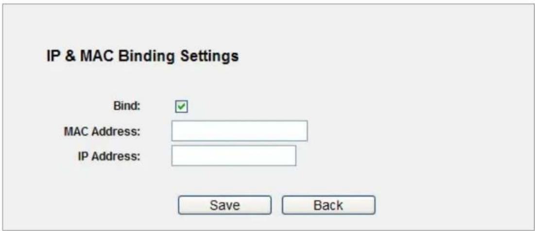
Figure 5-77 IP & MAC Binding Setting (Add & Modify)
To add IP & MAC Binding entries, follow the steps below.
Step 1. Click the Add New... button as shown in Figure 5-76.
Step 2. Enter the MAC Address and IP Address.
Step 3. Select the Bind checkbox.
Step 4. Click the Save button to save it.
To modify or delete an existing entry, follow the steps below.
Step 1. Find the desired entry in the table.
Step 2. Click Modify or Delete as desired on the Modify column.
To find an existing entry, follow the steps below.
Step 1. Click the Find button as shown in Figure 5-76.
Step 2. Enter the MAC Address or IP Address.
Step 3. Click the Find button in the page as shown in Figure 5-78.
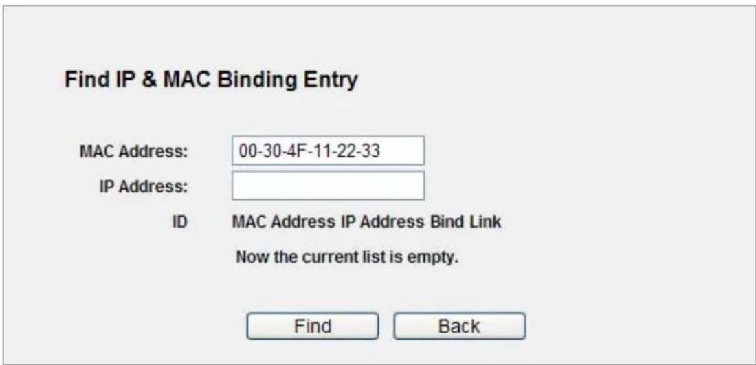
Figure 5-78 Find IP & MAC Binding Entry
Click the Enable All button to make all entries enabled.
Click the Delete All button to delete all entries.
5.16.2 ARP List
To manage the computer, you could observe the computers in the LAN by checking the relationship of MAC address and IP address on the ARP list, and you could configure the items on the ARP list also. This page displays the ARP List; it shows all the existing IP & MAC Binding entries (shown in Figure 5-79).
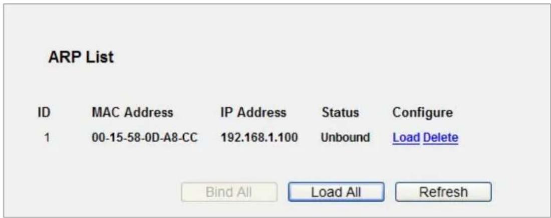
Figure 5-79 ARP List
The page includes the following fields:
| Object Description | |
| MAC Address | The MAC address of the controlled computer in the LAN. |
| IP Address | The assigned IP address of the controlled computer in the LAN. |
| Status | Indicates whether or not the MAC and IP addresses are bound. |
| Configure | Load or delete an item.Load - Load the item to the IP & MAC Binding list.Delete - Delete the item. |
Click the Bind All button to bind all the current items, available after enable.
Click the Load All button to load all items to the IP & MAC Binding list.
Click the Refresh button to refresh all items.

An item could not be loaded to the IP & MAC Binding list if the IP address of the item has been loaded before. Error warning will prompt as well. Likewise, "Load All" only loads the items without interference to the IP & MAC Binding list.
5.17 Dynamic DNS
Choose menu "Dynamic DNS", and you can configure the Dynamic DNS function.
The Router offers the DDNS (Dynamic Domain Name System) feature, which allows the hosting of a website, FTP server, or e-mail server with a fixed domain name (named by yourself) and a dynamic IP address, and then your friends can connect to your server by entering your domain name no matter what your IP address is. Before using this feature, you need to sign up for DDNS service providers such as www.comexe.cn, www.dyndns.org, or www.no-ip.com. The Dynamic DNS client service provider will give you a password or key.
5.17.1 Comexe.cn DDNS
If the dynamic DNS Service Provider you select is www.comexe.cn, the page will appear as shown in Figure 5-80.
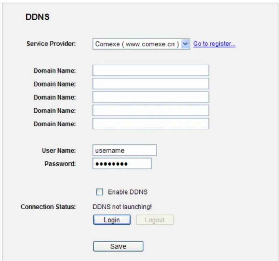
Figure 5-80 Comexe.cn DDNS Settings
To set up for DDNS, follow these instructions:
Step 1. Type the Domain Name received from your dynamic DNS service provider.
Step 2. Type the User Name for your DDNS account.
Step 3. Type the Password for your DDNS account.
Step 4. Click the Login button to log in to the DDNS service.
Connection Status -The status of the DDNS service connection is displayed here.
Click Logout to log out of the DDNS service.
5.17.2 Dyndns.org DDNS
If the dynamic DNS Service Provider you select is www.dyndns.org, the page will appear as shown in Figure 5-81.
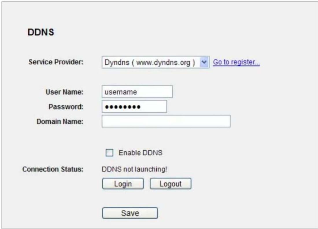
Figure 5-81 Dyndns.org DDNS Settings
To set up for DDNS, follow these instructions:
Step 1. Type the User Name for your DDNS account.
Step 2. Type the Password for your DDNS account.
Step 3. Type the Domain Name you received from dynamic DNS service provider here.
Step 4. Click the Login button to log in to the DDNS service.
Connection Status -The status of the DDNS service connection is displayed here.
Click Logout to logout of the DDNS service.
5.17.3 No-ip.com DDNS
If the dynamic DNS Service Provider you select is www.no-ip.com, the page will appear as shown in Figure 5-82.
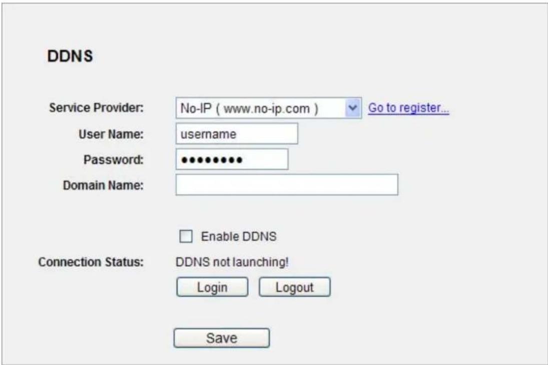
Figure 5-82 No-ip.com DDNS Settings
To set up for DDNS, follow these instructions:
Step 1. Type the User Name for your DDNS account.
Step 2. Type the Password for your DDNS account.
Step 3. Type the Domain Name you received from dynamic DNS service provider.
Step 4. Click the Login button to log in the DDNS service.
Connection Status - The status of the DDNS service connection is displayed here.
Click Logout to log out the DDNS service.
5.17.4 Planetddns.com DDNS
First of all, please go to http://www.planetddns.com to register a Planet DDNS account, and refer to the FAQ (http://www.planetddns.com/index.php/faq) for how to register a free account.
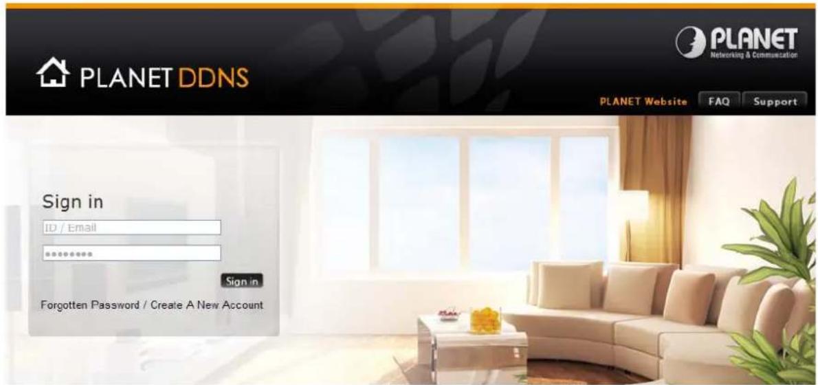
Figure 5-70 Planet DDNS Website
When you finish your DDNS account, please return to Network -> WAN option to set up your WAN type which can be connected to external network.
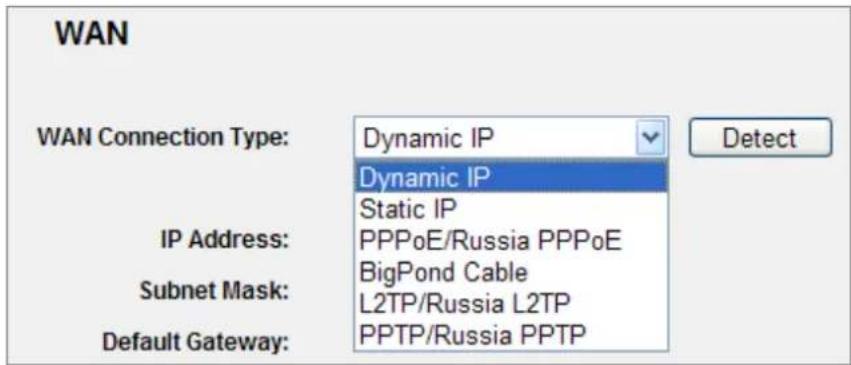
Figure 5-83 WAN Settings
To select dynamic DNS Service Provider www.planetddns.com, the page will appear as shown in Figure 5-84.
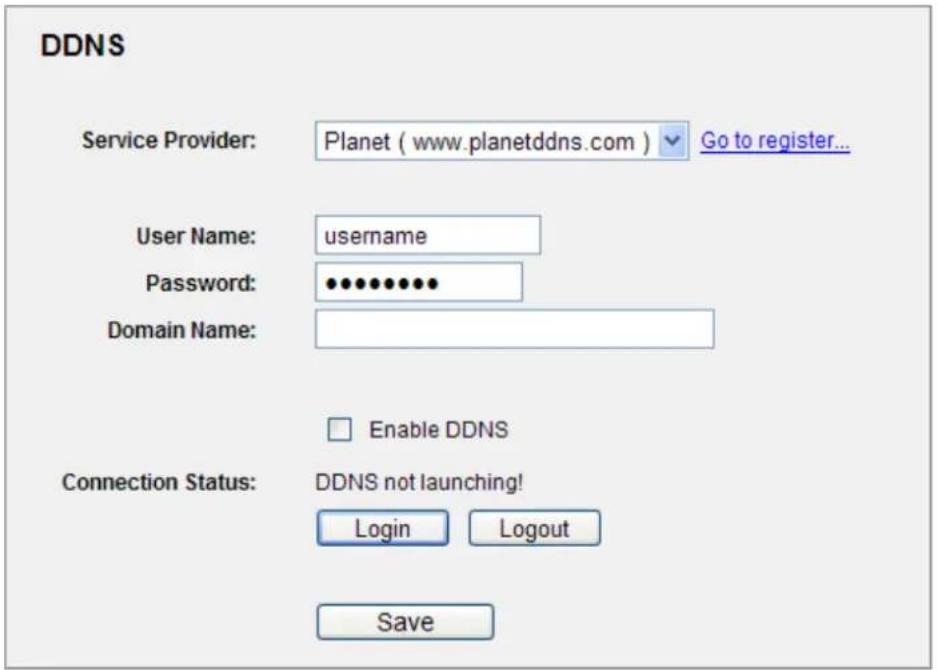
Figure 5-84 Planetddns.com DDNS Settings
To set up for DDNS, follow these instructions:
Step 1. Type the User Name for your DDNS account.
Step 2. Type the Password for your DDNS account.
Step 3. Type the Domain Name you received from dynamic DNS service provider.
Step 4. Click the Login button to log in the DDNS service.
Connection Status - The status of the DDNS service connection is displayed here.
Click Logout to log out the DDNS service.
Lastly you can go to My Devices page of Planet DDNS website to check if the "Last Connection IP" is displayed. This indicates your DDNS service is working properly.
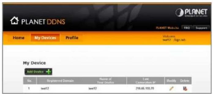
Figure 5-85 My Devices
5.18 System Tools
Choose menu "System Tools", and you can see the submenus under the main menu: Time Settings, Diagnostic, Firmware Upgrade, Factory Defaults, Backup & Restore, Reboot, Password, System Log and Statistics. Click any of them, and you will be able to configure the corresponding function. The detailed explanations for each submenu are provided below.
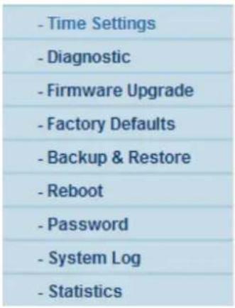
Figure 5-86 The System Tools menu
5.18.1 Time Settings
Choose menu "System Tools→Time Settings", and you can configure the time on the following screen.
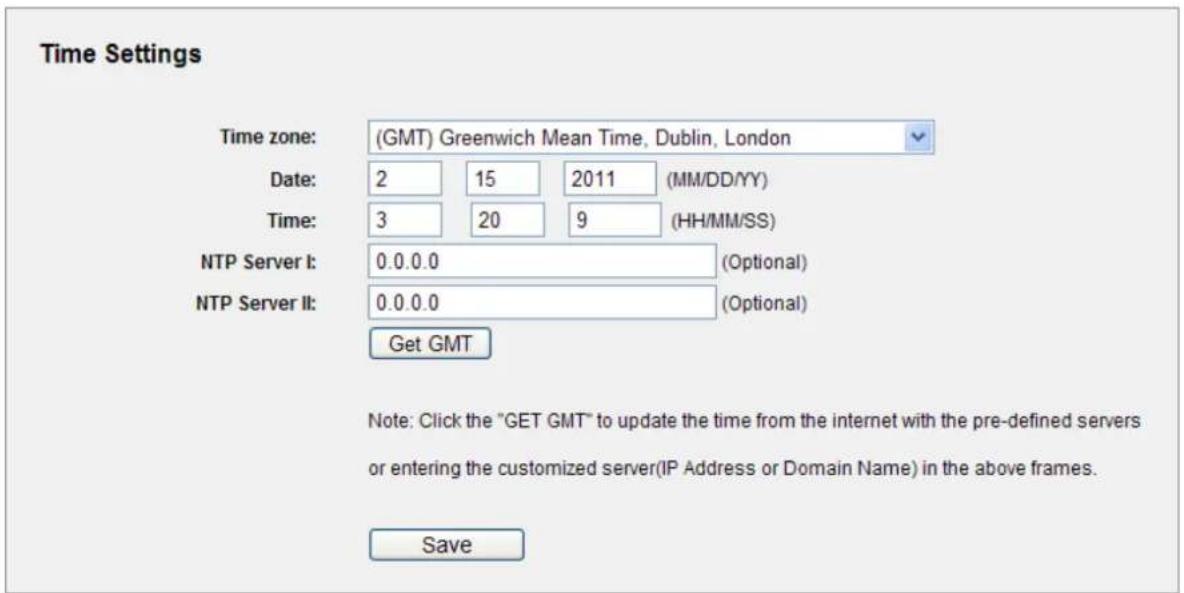
Figure 5-87 Time settings
The page includes the following fields:
| Object Description | |
| Time Zone | Select your local time zone from this pull down list. |
| Date | Enter your local date in MM/DD/YY into the right blanks. |
| Time | Enter your local time in HH/MM/SS into the right blanks. |
| NTP Server Prior | Enter the address for the NTP Server, then the Router will get the time from the NTP Server preferentially. In addition, the Router builds in some common NTP Servers, so it can get time automatically once it connects the Internet. |
To configure the system manually:
Step 1. Select your local time zone.
Step 2. Enter date and time in the right blanks.
Step 3. Click Save to save the configuration.
To configure the system automatically:
Step 1. Select your local time zone.
Step 2. Enter the IP address for NTP Server Prior.
Step 3. Click the Get GMT button to get system time from Internet if you have connected to the Internet.

This setting will be used for some time-based functions such as firewall. You must specify your time zone once you login to the router successfully, otherwise, these functions will not take effect.
The time will be lost if the router is turned off.
The router will obtain GMT automatically from Internet if it has already connected to Internet.
5.18.2 Diagnostic
Choose menu "System Tools → Diagnostic", and you can transact Ping or Traceroute function to check connectivity of your network in the following screen.
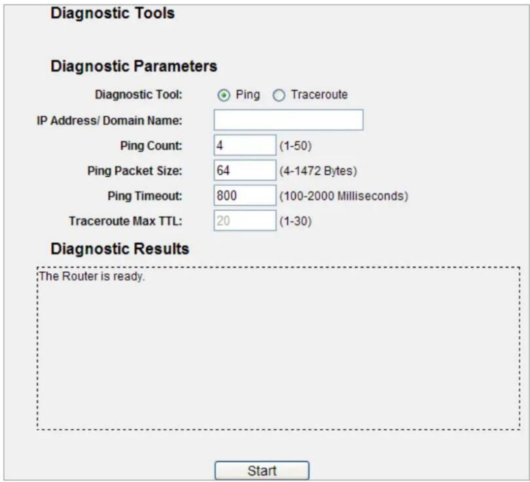
Figure 5-88 Diagnostic Tools
The page includes the following fields:
| Object Description | |
| Diagnostic Tool | Check the radio button to select one diagnostic too.◆ Ping - This diagnostic tool troubleshoots connectivity, reachability, and name resolution to a given host or gateway.◆ Traceroute - This diagnostic tool tests the performance of a connection. |
| IP Address/Domain Name | Type the destination IP address (such as 74.125.153.103) or Domain name (such as http://www.google.com) |
| Pings Count | The number of Ping packets for a Ping connection. |
| Ping Packet Size | The size of Ping packet. |
| Ping Timeout | Set the waiting time for the reply of each Ping packet. If there is no reply in the specified time, the connection is overtime. |
| Traceroute Max TTL | The max number of hops for a Traceroute connection. |
Click Start to check the connectivity of the Internet.

You can use ping/traceroute to test both numeric IP address or domain name. If pinging/tracerouting the IP address is successful, but pinging/tracerouting the domain name is not, you might have a name resolution problem. In this case, ensure that the domain name you are specifying can be resolved by using Domain Name System (DNS) queries.
The Diagnostic Results page displays the result of diagnosis.
If the result is similar to the following screen, the connectivity of the Internet is fine.
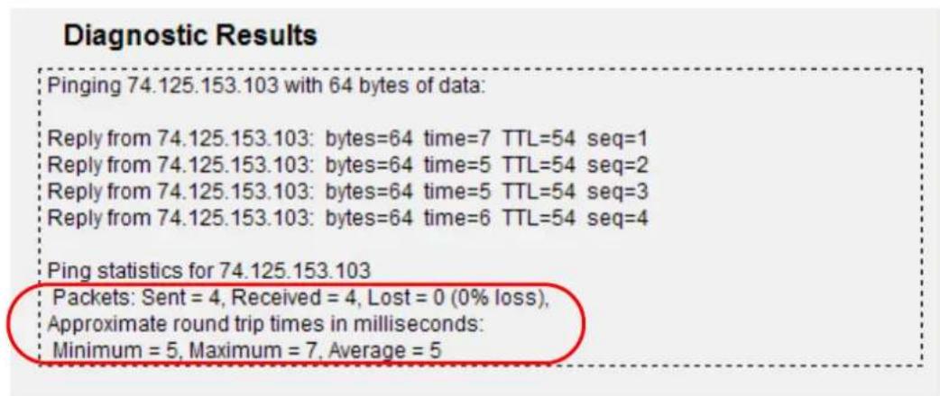
Figure 5-89 Diagnostic Results

Only one user can use this tool at one time. Options "Number of Pings", "Ping Size" and "Ping Timeout" are used for Ping function. Option "Tracert Hops" are used for Tracert function.
5.18.3 Firmware Upgrade
Choose menu "System Tools → Firmware Upgrade", and you can update the latest version of firmware for the Router on the following screen.
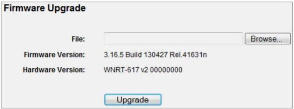
Figure 5-90 Firmware Upgrade
The page includes the following fields:
| Object Description | |
| Firmware Version | This displays the current firmware version. |
| Hardware Version | This displays the current hardware version. The hardware version of the upgrade file must accord with the Router's current hardware version. |
To upgrade the Router's firmware, follow these instructions below:
Step 1. Download a more recent firmware upgrade file from our website.
Step 2. Type the path and file name of the update file into the File field. Or click the Browse button to locate the update file.
Step 3. Click the Upgrade button.

New firmware versions posted at the website of PLANET Technology can be downloaded for free. There is no need to upgrade the firmware unless the new firmware has a new feature you want to use. However, when experiencing problems caused by the Router rather than the configuration, you can try to upgrade the firmware.
When you upgrade the Router's firmware, you may lose its current configurations, so before upgrading the firmware please write down some of your customized settings to avoid losing important settings.
Do not turn off the Router or press the Reset button while the firmware is being upgraded; otherwise, the Router may be damaged.
The Router will reboot after the upgrading has been finished.
5.18.4 Factory Defaults
Choose menu "System Tools → Factory Defaults", and you can restore the configurations of the Router to factory defaults on the following screen
Factory Defaults
Click the following button to reset all configuration settings to their default values.
Restore
Figure 5-91 Restore Factory Default
Click the Restore button to reset all configuration settings to their default values.
The default User Name: admin
The default Password: admin
The default IP Address: 192.168.1.1
The default Subnet Mask: 255.255.255.0

Any settings you have saved will be lost when the default settings are restored.
Choose menu "System Tools Backup & Restore", and you can save the current configuration of the Router as a backup file and restore the configuration via a backup file as shown in Figure 5-92.
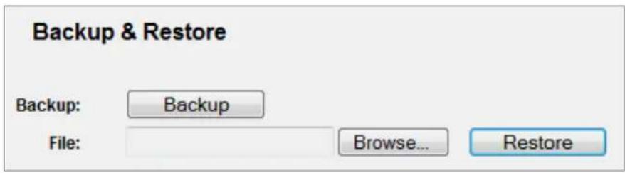
Figure 5-92 Backup & Restore Configuration
- Click the Backup button to save all configuration settings as a backup file in your local computer.
To upgrade the Router's configuration, follow these instructions.
Step 1. Click the Browse... button to locate the update file for the Router, or enter the exact path to the Setting file in the text box.
Step 2. Click the Restore button.

The current configuration will be covered by the uploading configuration file. The upgrade process lasts for 20 seconds and the Router will restart automatically. Keep the Router power on during the upgrading process to prevent any damage.
5.18.6 Reboot
Choose menu "System Tools → Reboot", and you can click the Reboot button to reboot the Router via the next screen.
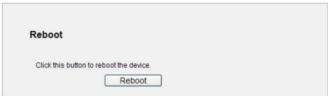
Figure 5-93 Reboot the Router
Some settings of the Router will take effect only after rebooting, which include
- Change the LAN IP Address (system will reboot automatically).
- Change the DHCP Settings.
- Change the Wireless configurations.
◆ Change the Web Management Port. - Upgrade the firmware of the Router (system will reboot automatically).
Restore the Router's settings to factory defaults (system will reboot automatically).
Update the configuration with the file (system will reboot automatically.
5.18.7 Password
Choose menu "System Tools → Password", and you can change the factory default user name and password of the Router in the next screen as shown in Figure 5-94.
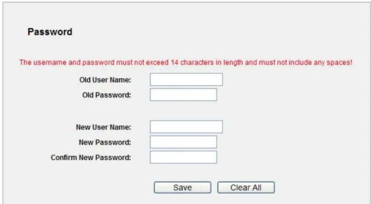
Figure 5-94 Password
It is strongly recommended that you should change the factory default user name and password of the Router, because all users who try to access the Router's Web-based utility or Quick Setup will be prompted for the Router's default user name and password.

The new user name and password must not exceed 14 characters in length and not include any spaces. Enter the new Password twice to confirm.
Click the Save button when finished.
Click the Clear All button to clear all.
5.18.8 System Log
Choose menu "System Tools → System Log", and you can view the logs of the Router.
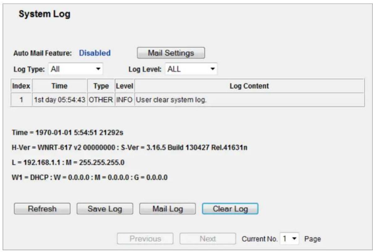
Figure 5-95 System Log
The page includes the following fields:
| Object Description | |
| Auto Mail Feature | Indicates whether auto mail feature is enabled or not. |
| Mail Settings | Set the receiving and sending mailbox address, server address, validation information as well as the timetable for Auto Mail Feature, as shown in Figure 5-96 . |
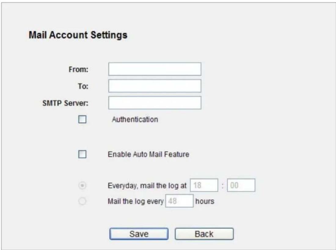
Figure 5-96 Mail Account Settings
The page includes the following fields:
| Object Description | |
| From Your mail box address. | The Router would connect it to send logs. |
| To Recipient's address. The destination mailbox where the logs would be received. | |
| SMTP Server | Your smtp server. It corresponds with the mailbox filled in the From field. You can log on the relevant website for Help if you are not clear with the address. |
| Authentication Most SMTP Server requires Authentication. It is required by most mailboxes that need User Name and Password to log in. | |
| User Name Your mail account name filled in the From field. The part behind @ is excluded. | |
| Password Your mail account password. | |
| Confirm The Password Enter the password again to confirm. | |
| Enable Auto Mail Feature | Select it to mail logs automatically. You could mail the current logs either at a specified time everyday or by intervals, but only one could be the current effective rule. Enter the desired time or intervals in the corresponding field as shown in Figure 5-96 |

Only when you select Authentication, you have to enter the User Name and Password in the following fields.
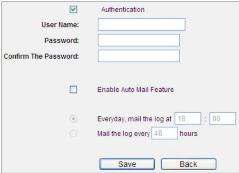
Figure 5-97 Mail Account Settings - Authentication
Click Save to keep your settings.
Click Back to return to the previous page.
The system log page includes the following fields:
| Object Description | |
| Log Type | By selecting the log type, only logs of this type will be shown. |
| Log Level | By selecting the log level, only logs of this level will be shown. |
| Refresh | Refresh the page to show the latest log list. |
| Save Log | Click to save all the logs in a txt file. |
| Mail Log | Click to send an email of current logs manually according to the address and validation information set in Mail Settings. |
| Clear Log | All the logs will be deleted from the Router permanently, not just from the page. |
5.18.9 Statistics
Choose menu "System Tools → Statistics", and you can view the statistics of the Router, including total traffic and current traffic of the last Packets Statistic Interval.
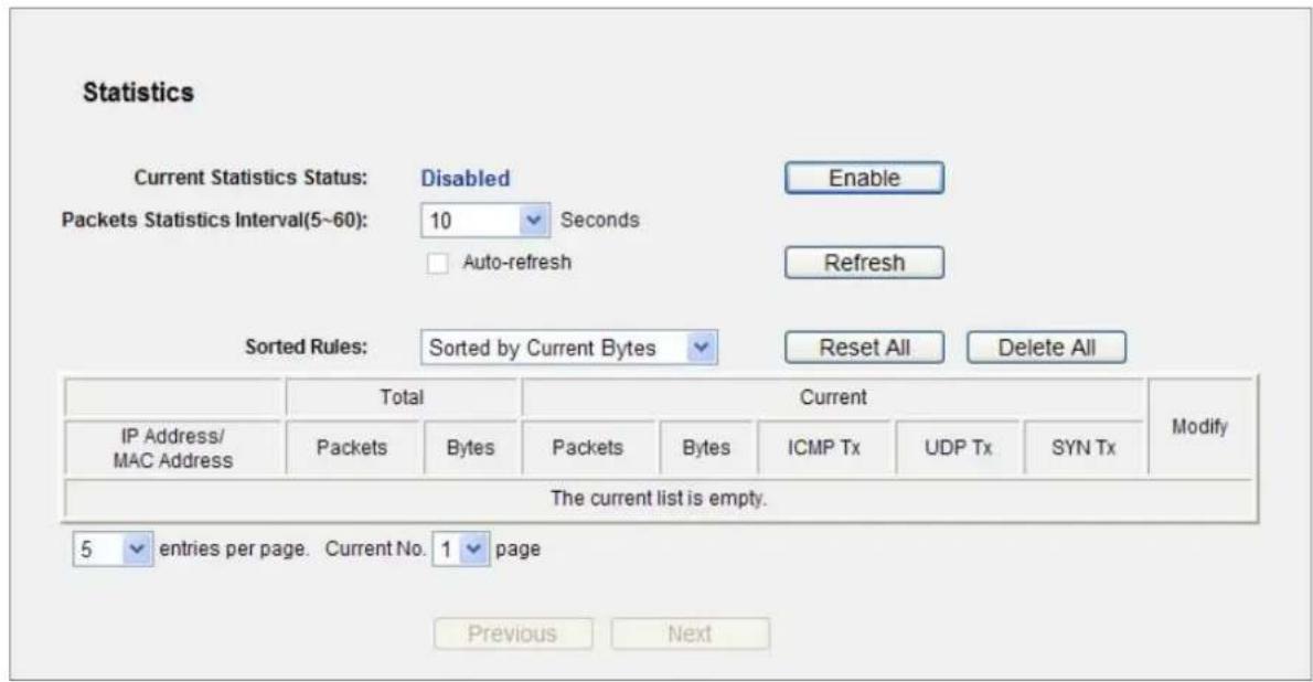
Figure 5-98 Statistics
The page includes the following fields:
| Object Description | |
| Current Statistics Status | Enable or Disable. The default value is disabled. To enable, click the Enable button. If disabled, the function of DoS protection in Security settings will disabled. |
| Packets Statistics Interval (5-60) | The default value is 10. Select a value between 5 and 60 seconds in the pull-down list. The Packets Statistic interval indicates the time section of the packets statistic. |
| Sorted Rules | Choose how displayed statistics are sorted. |
Select the Auto-refresh checkbox to refresh automatically.
Click the Refresh button to refresh immediately.
Click Reset All to reset the values of all the entries to zero.
Click Delete All to delete all entries in the table.
Statistics Table:
| IP/MAC Address | The IP and MAC address are displayed with related statistics. | |
| Total | Packets | The total number of packets received and transmitted by the Router. |
| Bytes | The total number of bytes received and transmitted by the Router. | |
| Current | Packets | The total number of packets received and transmitted in the last Packets Statistic interval seconds. |
| Bytes | The total number of bytes received and transmitted in the last Packets Statistic interval seconds. | |
| ICMP Tx | The number of the ICMP packets transmitted to WAN per second at the specified Packets Statistics interval. It is shown like “current transmitting rate / Max transmitting rate”. | |
| UDP Tx | The number of UDP packets transmitted to the WAN per second at the specified Packets Statistics interval. It is shown like “current transmitting rate / Max transmitting rate”. | |
| TCP SYN Tx | The number of TCP SYN packets transmitted to the WAN per second at the specified Packets Statistics interval. It is shown like “current transmitting rate / Max transmitting rate”. | |
| Modify | Reset | Reset the value of he entry to zero. |
| Delete | Delete the existing entry in the table. | |
There would be 5 entries on each page. Click Previous to return to the previous page and Next to the next page.
Chapter 6. Quick Connection to a Wireless Network
6.1 Windows XP (Wireless Zero Configuration)
Step 1: Right-Click on the wireless network icon displayed in the system tray
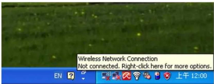
Figure 6-1 Wireless Zero Configuration
Step 2: Select [View Available Wireless Networks]
Step 3: Highlight and select the wireless network (SSID) to connect
(1) Select SSID [PLANET_WNRT-617]
(2) Click the [Connect] button
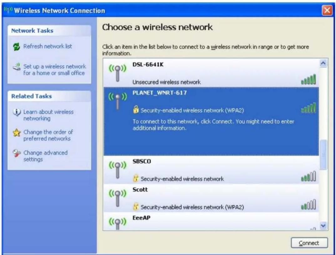
Figure 6-2 Choose a wireless network
Step 4: Enter the encryption key of the Wireless Router
(1) The Wireless Network Connection box will appear
(2) Enter the encryption key that is configured in Section 5.6.2
(3) Click the [Connect] button
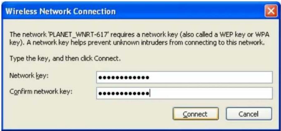
Figure 6-3 Enter the encryption key
Step 5: Check if "Connected" is displayed
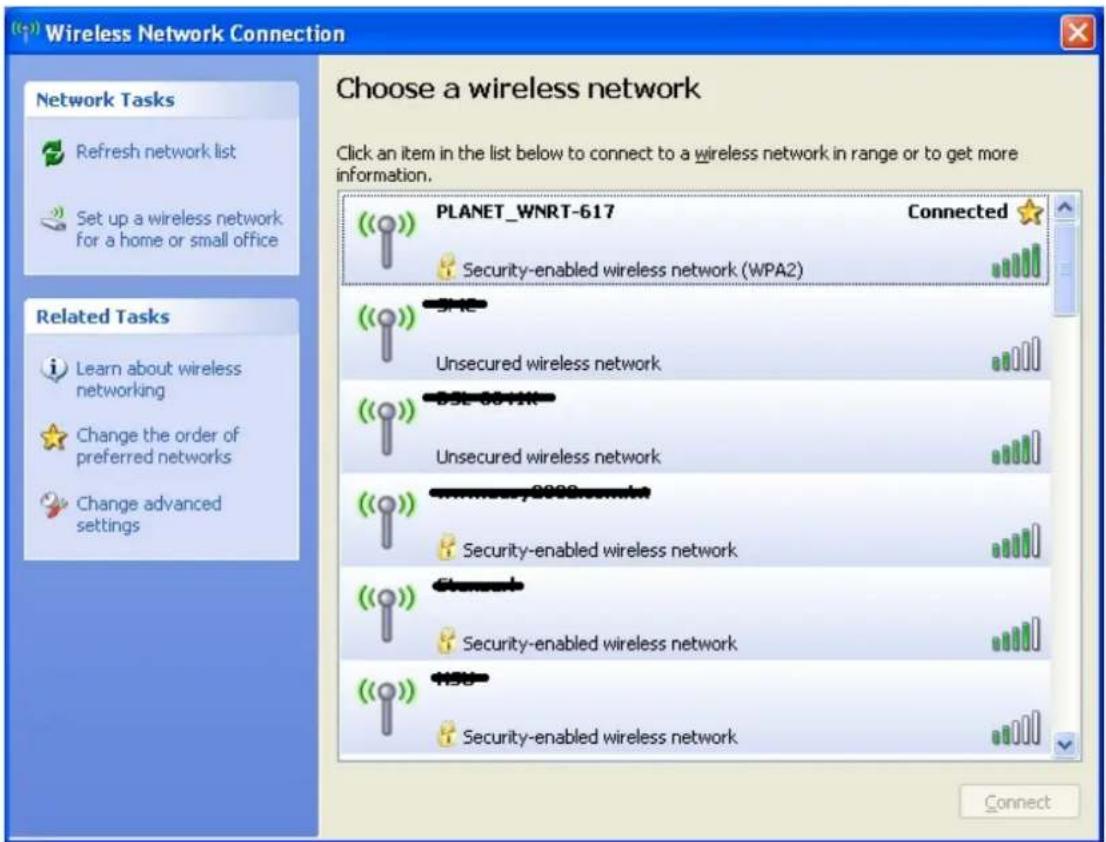
Figure 6-4 Wireless Network Connected

Some laptops are equipped with a "Wireless ON/OFF" switch for the internal wireless LAN. Make sure the hardware wireless switch is switch to "ON" position.
6.2 Windows 7 (WLAN AutoConfig)
WLAN AutoConfig service is built-in in Windows 7 that can be used to detect and connect to wireless network. This built-in wireless network connection tool is similar to wireless zero configuration tool in Windows XP.
Step 1: Right-Click on the network icon displayed in the system tray

Figure 6-5 WLAN AutoConfig
Step 2: Highlight and select the wireless network (SSID) to connect
(1) Select SSID [PLANET_WNRT-617]
(2) Click the [Connect] button
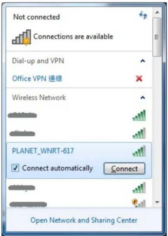
Figure 6-6 WLAN AutoConfig window

If you will be connecting to this Wireless Router in the future, check [Connect automatically].
Step 4: Enter the encryption key of the Wireless Router
(1) The Connect to a Network box will appear
(2) Enter the encryption key that is configured in Section 5.6.2
(3) Click the [OK] button
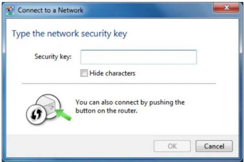
Figure 6-7 WLAN AutoConfig – type the network security key
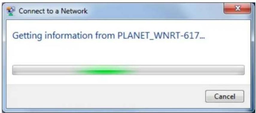
Figure 6-8 WLAN AutoConfig – connecting
Step 5: Check if "Connected" is displayed
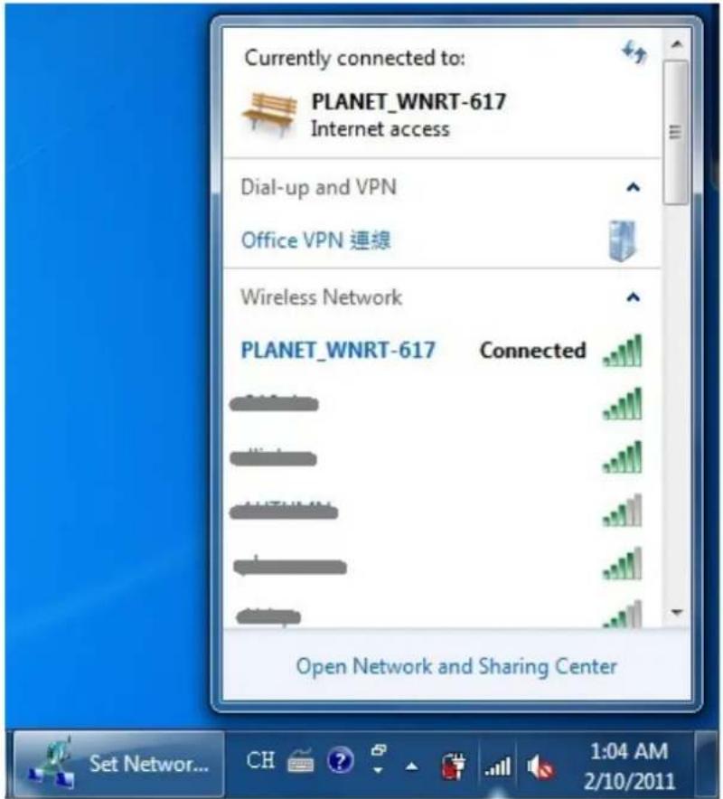
Figure 6-9 WLAN AutoConfig – Connected
6.3 Mac OS X 10.x
Step 1: Right-Click on the network icon displayed in the system tray The AirPort Network Connection menu will appear

natural_image
Desktop interface with icons for news, Wi-Fi, and U.S. flag on a pink background (no readable text or symbols)Figure 6-10 The AirPort Network Connection icon
Step 2: Highlight and select the wireless network (SSID) to connect
(1) Select and SSID [PLANET_WNRT-617]
(2) Double-click on the selected SSID

Figure 6-11 The AirPort Network Connection menu
Step 4: Enter the encryption key of the Wireless Router
(1) Enter the encryption key that is configured in Section 5.6.2
(2) Click the [OK] button
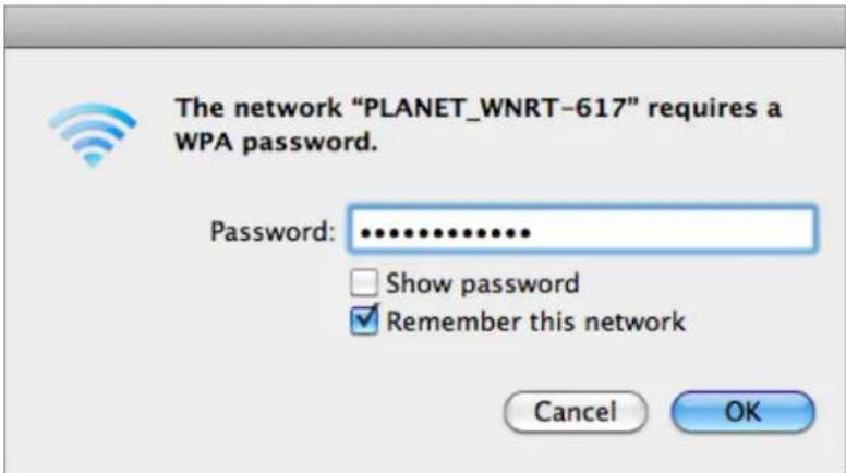
Figure 6-12 The AirPort Network Connection – enter password

If you will connect this Wireless Router in the future, check [Remember this network].
Step 5: Check if the AirPort is connected to the selected wireless network. If "Yes", then there will be a "check" symbol in the front of the SSID.
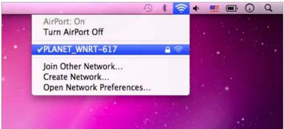
Figure 6-13 The AirPort Network Connection – connected
6.4 iPhone / iPod Touch / iPad
Step 1: Tap the [Settings] icon displayed in the home screen
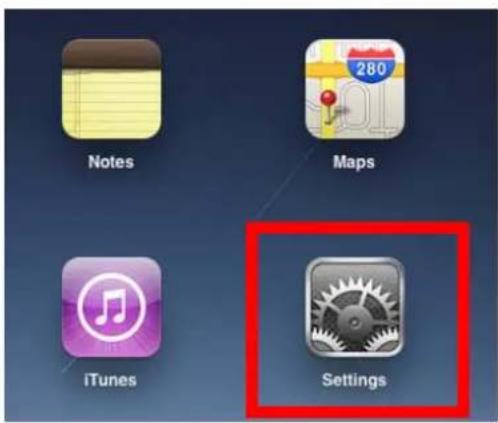
Figure 6-14 The Wi-Fi Settings in iPhone/iPod Touch/iPad
Step 2: Check Wi-Fi setting and select the available wireless network
(1) Tap [General] \ [Network]
(2) Tap [Wi-Fi]
If this is the first time to connect to the Wireless Router, it should show "Not Connected".
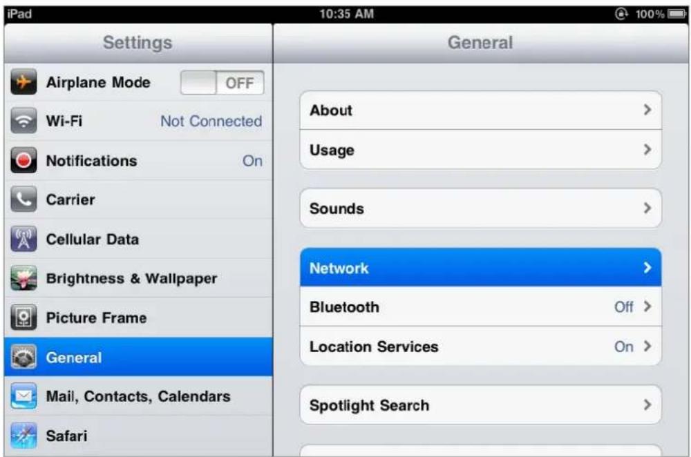
Figure 6-15 General Settings
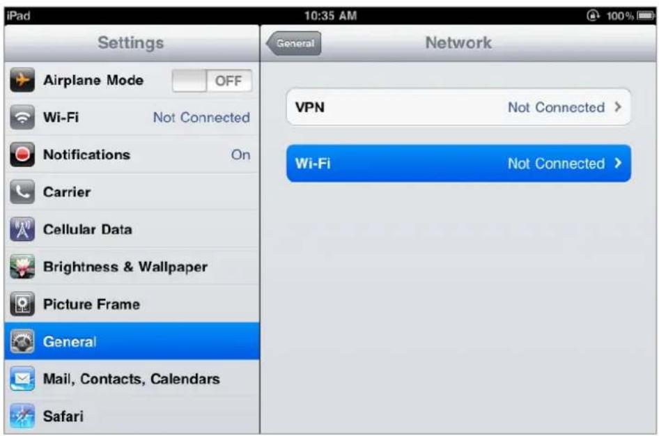
Figure 6-16 General Settings – Not Connected
Step 3: Tap the target wireless network (SSID) in "Choose a Network..."
(1) Turn on Wi-Fi by tapping "Wi-Fi"
(2) Select SSID [PLANET_WNRT-617]
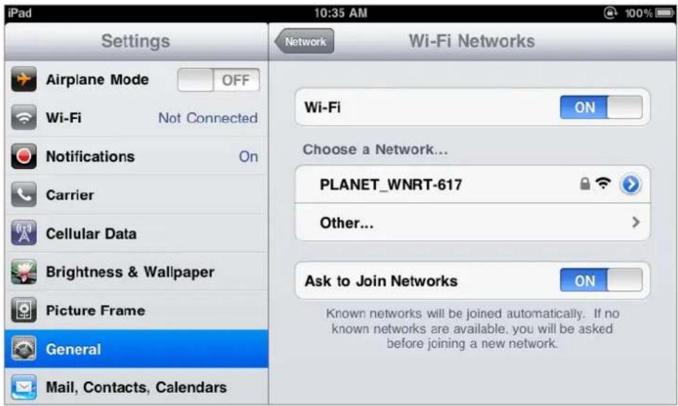
Figure 6-17 General Settings – Wi-Fi On
Step 4: Enter the encryption key of the Wireless Router
(1) The password input screen will be displayed
(2) Enter the encryption key that is configured in Section 5.6.2
(3) Tap the [Join] button
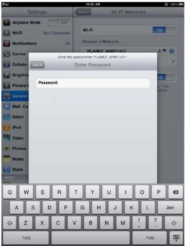
Figure 6-18 General Settings – Enter password
Step 5: Check if the iDevice is connected to the selected wireless network.
If "Yes", then there will be a "check" symbol in the front of the SSID.
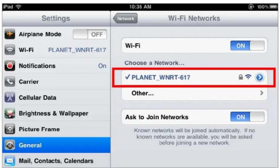
Figure 6-19 General Settings – Wi-Fi Network Connected
Appendix A: FAQ
1. How do I configure the Router to access Internet by ADSL users?
1) First, configure the ADSL Modem configured in RFC1483 bridge model.
2) Connect the Ethernet cable from your ADSL Modem to the WAN port on the Router. Plug the telephone cord into the Line port of the ADSL Modem.
3) Login to the Router, click the "Network" menu on the left of your browser, and click "WAN" submenu. On the WAN page, select "PPPoE" for WAN Connection Type. Type user name in the "User Name" field and password in the "Password" field, finish by clicking "Connect".
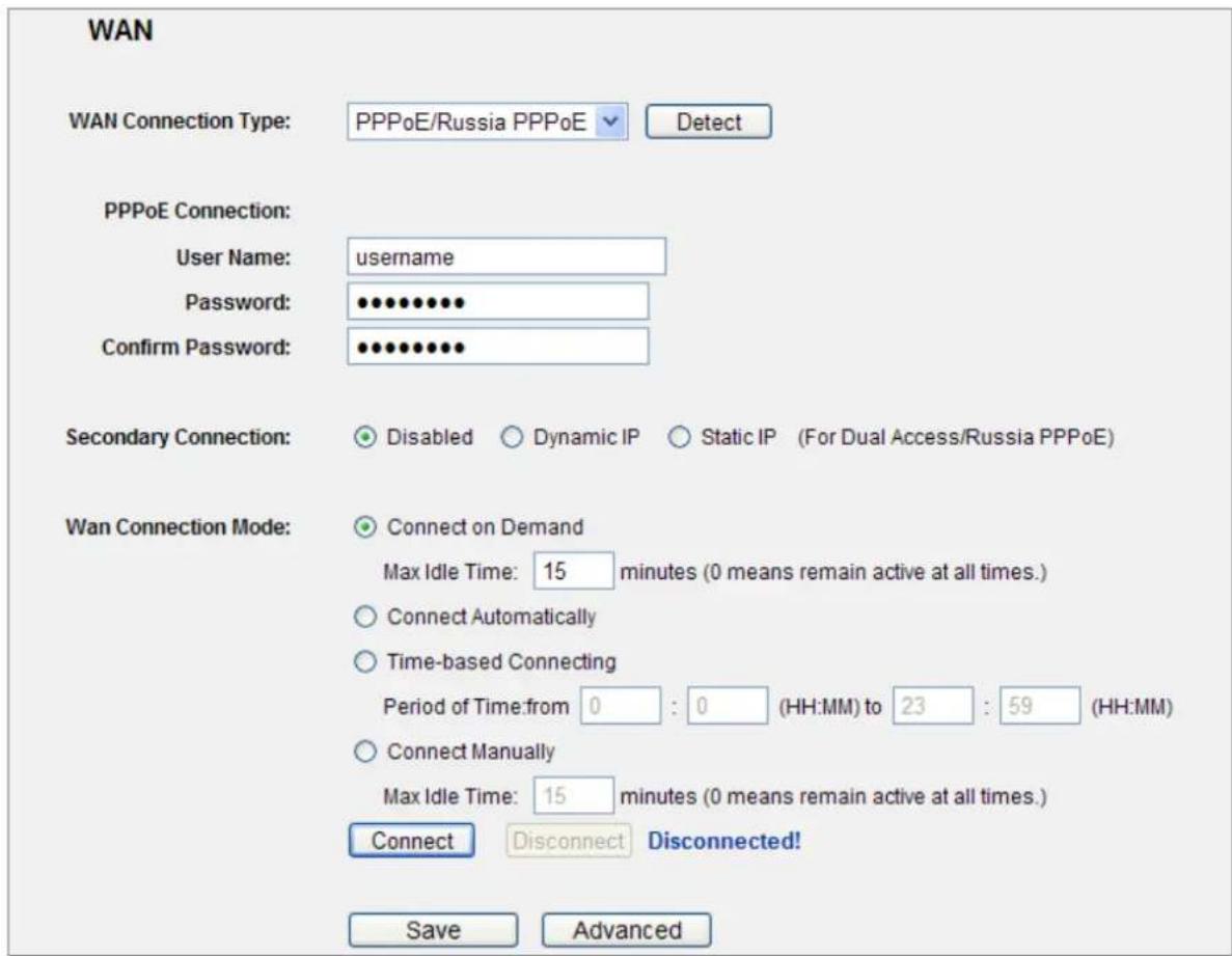
Figure A-1 PPPoE Connection Type
4) If your ADSL lease is in "pay-according-time" mode, select "Connect on Demand" or "Connect Manually" for Internet connection mode. Type an appropriate number for "Max Idle Time" to avoid wasting paid time. Otherwise, you can select "Auto-connecting" for Internet connection mode.

-
Sometimes the connection cannot be disconnected although you specify a time to Max Idle Time, since some applicants are visiting the Internet continually in the background.
-
If you are a Cable user, please configure the Router following the above steps.
2. How do I configure the Router to access Internet by Ethernet users?
1) Login to the Router, click the "Network" menu on the left of your browser, and click "WAN" submenu. On the WAN page, select "Dynamic IP" for "WAN Connection Type", finish by clicking "Save".
2) Some ISPs require that you register the MAC Address of your adapter, which is connected to your cable/DSL Modem during installation. If your ISP requires MAC register, login to the Router and click the "Network" menu link on the left of your browser, and then click "MAC Clone" submenu link. On the "MAC Clone" page, if your PC's MAC address is proper MAC address, click the "Clone MAC Address" button and your PC's MAC address will fill in the "WAN MAC Address" field. Or else, type the MAC Address into the "WAN MAC Address" field. The format for the MAC Address is XX-XX-XX-XX-XX-XX. Then click the "Save" button. It will take effect after rebooting.
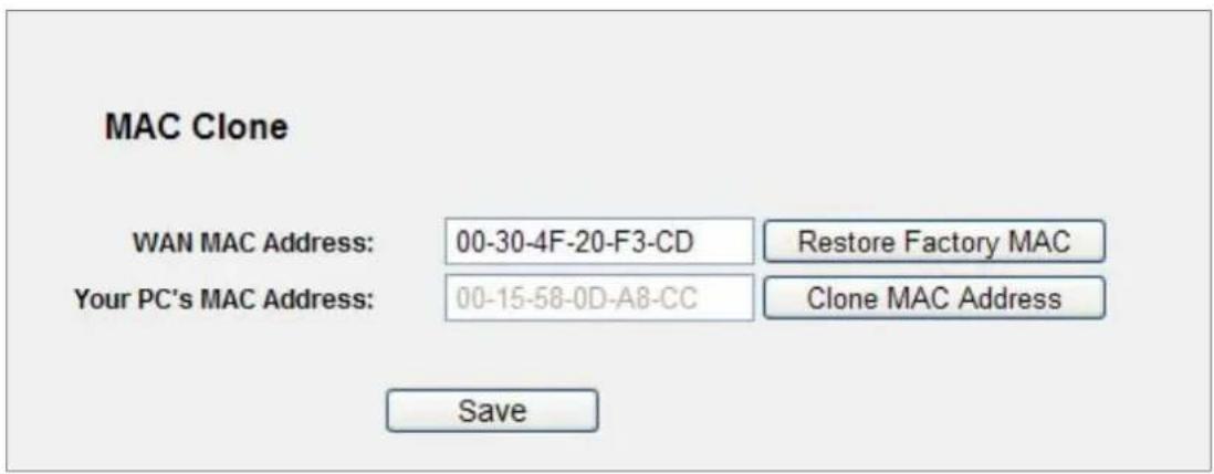
Figure A-2 MAC Clone
3. I want to use Netmeeting, what do I need to do?
1) If you start Netmeeting as a host, you don't need to do anything with the Router.
2) If you start as a response, you need to configure Virtual Server or DMZ Host and make sure the H323 ALG is enabled.
3) How to configure Virtual Server: Log in to the Router, click the "Forwarding" menu on the left of your browser, and click "Virtual Servers" submenu. On the "Virtual Servers" page, click Add New.... Then on the "Add or Modify a Virtual Server Entry" page, enter "1720" for the
"Service Port" blank, and your IP address for the "IP Address" blank, taking 192.168.1.169 for an example, remember to Enable and Save.
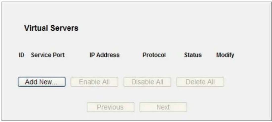
Figure A-3 Virtual Servers
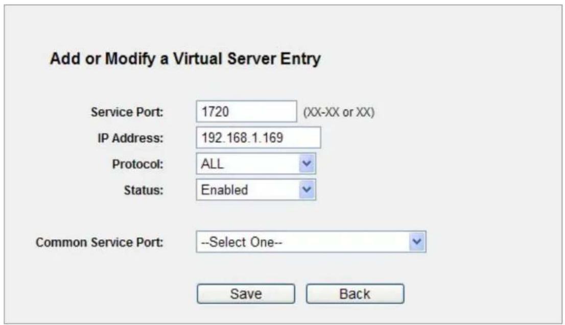
Figure A-4 Add or Modify a Virtual Server Entry

Your opposite side should call your WAN IP, which is displayed on the "Status" page.
4) How to enable DMZ Host: Log in to the Router, click the "Forwarding" menu on the left of your browser, and click "DMZ" submenu. On the "DMZ" page, click Enable radio button and
type your IP address into the "DMZ Host IP Address" field, using 192.168.1.169 as an example, remember to click the Save button.
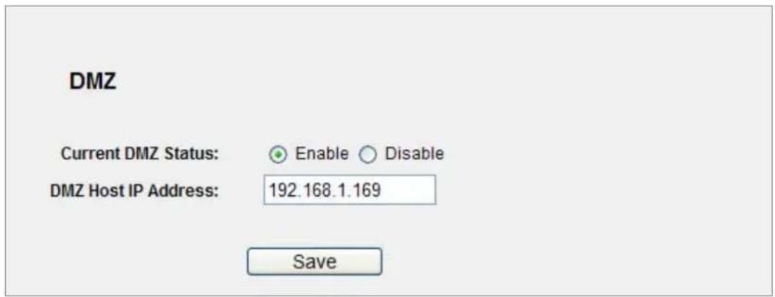
Figure A-5 D M Z
5) How to enable H323 ALG: Log in to the Router, click the "Security" menu on the left of your browser, and click "Basic Security" submenu. On the "Basic Security" page, check the Enable radio button next to H323 ALG. Remember to click the Save button.
Basic Security
Firewall
SPI Firewall:
Enable Disable
VPN
PPTP Passthrough:
Enable Disable
L2TP Passthrough:
Enable Disable
IPSec Passthrough:
Enable Disable
ALG
FTP ALG:
Enable Disable
TFTP ALG:
Enable Disable
H323 ALG:
Enable ○ Disable
RTSP ALG:
Enable Disable
Save
Figure A-6 Basic Security
4. I want to build a WEB Server on the LAN, what should I do?
1) Because the WEB Server port 80 will interfere with the WEB management port 80 on the Router, you must change the WEB management port number to avoid interference.
2) To change the WEB management port number: Log in to the Router, click the "Security" menu on the left of your browser, and click "Remote Management" submenu. On the "Remote Management" page, type a port number except 80, such as 88, into the "Web Management Port" field. Click Save and reboot the Router.
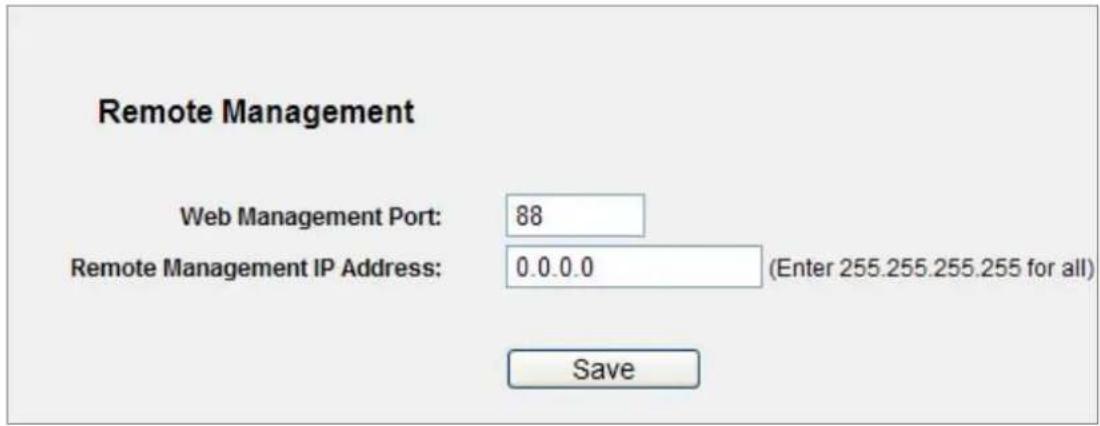
Figure A-7 Remote Management

If the above configuration takes effect, you can configure the Router by typing http://192.168.1.1:88 (the Router's LAN IP address: Web Management Port) in the address field of the Web browser.
3) Log in to the Router, click the "Forwarding" menu on the left of your browser, and click the "Virtual Servers" submenu. On the "Virtual Servers" page, click Add New..., then on the "Add or Modify a Virtual Server" page, enter "80" into the blank next to the "Service Port", and your IP address next to the "IP Address", assuming 192.168.1.188 for an example, remember to Enable and Save.
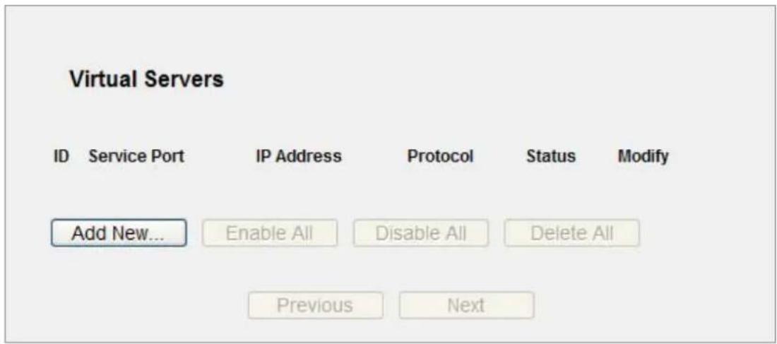
Figure A-8 Virtual Servers
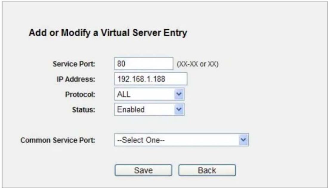
Figure A-9 Add or Modify a Virtual Server Entry
5. The wireless stations cannot be connected to the Router.
1) Make sure the "Wireless Router Radio" is enabled.
2) Make sure that the wireless stations' SSID is in accord with the Router's SSID.
3) Make sure the wireless stations have the right KEY for encryption when the Router is encrypted.
4) If the wireless connection is ready, but you can't access the Router, check the IP Address of your wireless stations.
Appendix B: Configuring the PCs
In this section, we'll introduce how to install and configure the TCP/IP correctly in Windows XP. First make sure your Ethernet Adapter is working, refer to the adapter's manual if needed.
2. Install TCP/IP component
1) On the Windows taskbar, click the Start button, point to Settings, and then click Control Panel.
2) Click the Network and Internet Connections icon, and then click on the Network Connections tab in the appearing window.
3) Right click the icon shown below, select Properties on the prompt page.
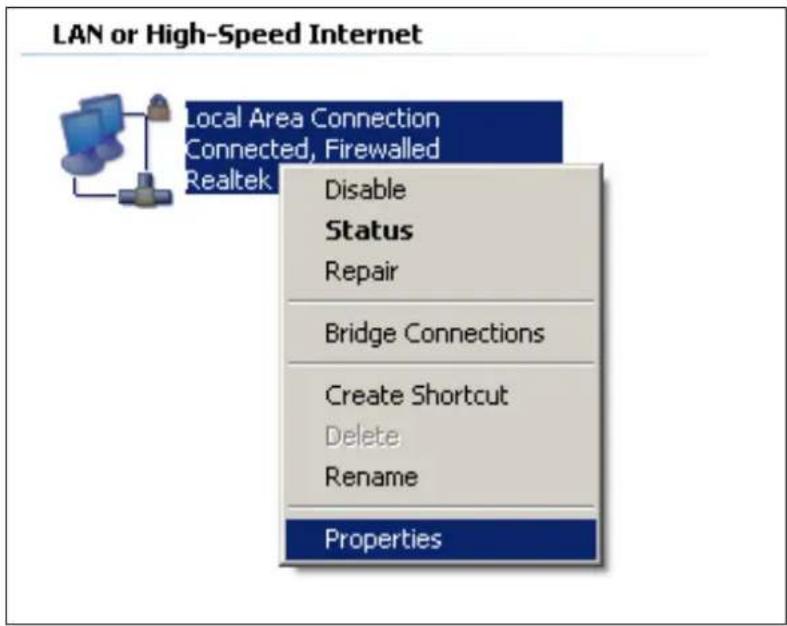
Figure B-1 Network Connection Properties
4) On the prompt page shown below, double click on the Internet Protocol (TCP/IP).
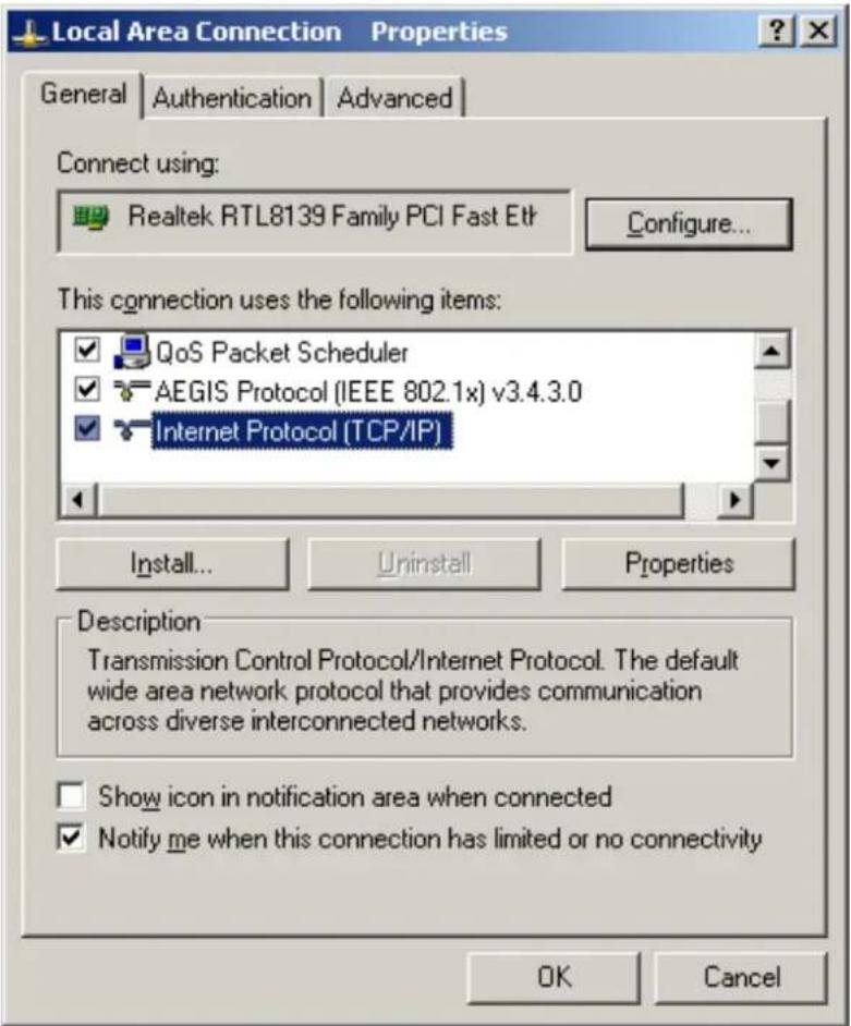
Figure B-2 TCP/IP Settings
5) The following TCP/IP Properties window will display and the IP Address tab is open on this window by default.
Now you have two ways to configure the TCP/IP protocol below:
Setting IP address automatically
Select Obtain an IP address automatically, Choose Obtain DNS server automatically, as shown in the Figure below:
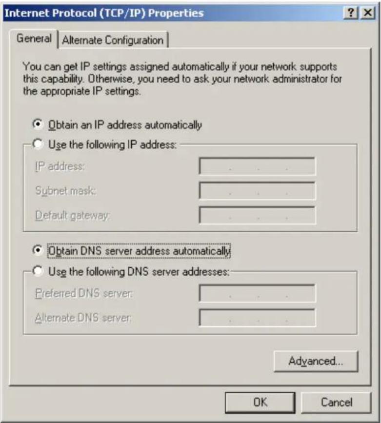
Figure B-3 TCP/IP – Obtain an IP address automatically
Setting IP address manually
1 Select Use the following IP address radio button.
2 If the Router's LAN IP address is 192.168.1.1, type in IP address 192.168.1.x (x is from 2 to 254), and Subnet mask 255.255.255.0.
3 Type the Router's LAN IP address (the default IP is 192.168.1.1) into the Default gateway field.
4 Select Use the following DNS server addresses radio button. In the Preferred DNS Server field you can type the DNS server IP address which has been provided by your ISP
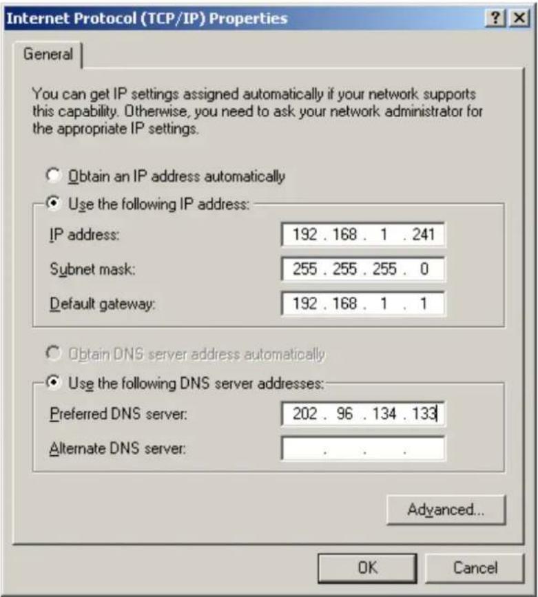
Figure B-4 TCP/IP Settings – Static IP
Now click OK to keep your settings.
Appendix C: Specifications
| Product | WNRT-617150Mbps 802.11n Wireless Broadband Router | |
| Hardware Specifications | ||
| Interface | WAN Port: | 1 x 10/100Mbps Auto MDI/MDI-X RJ45 port |
| LAN Port: | 4 x 10/100Mbps Auto MDI/MDI-X RJ45 port | |
| Antenna | Gain: 1 x Fixed 5dBi Antenna | |
| Orientation: | Omni-directional | |
| Power Button Power On/Off button at rear panel | ||
| WPS / Reset Button | WPS / Reset button at front panelPush for above 5 seconds to reset to factory default setting | |
| LED Indicators | PWR, SYS, WLAN, LAN x 4, WAN, WPS with green light | |
| Material Plastic | ||
| Wireless Interface Specifications | ||
| Standard Compliance with IEEE 802.11b/g/n | ||
| Frequency Band | 2.4~2.4835GHz | |
| Extend Frequency | DSSS | |
| Modulation Type | DBPSK, DQPSK, QPSK, CCK and OFDM (BPSK/QPSK/16-QAM/ 64-QAM) | |
| Data Transmission Rates | 11n: 135/121.5/108/81/54/40.5/27/13.5Mbps130/117/104/78/52/39/26/13Mbps65/58.5/52/39/26/19.5/13/6.5Mbps (Dynamic)11g: 54/48/36/24/18/12/9/6Mbps (Dynamic)11b: 11/5.5/2/1Mbps (Dynamic) | |
| Transmission Distance | Indoor up to 100mOutdoor up to 300m (it is limited to the environment) | |
| Channel | America/ FCC: 2.414~2.462GHz (11 Channels)Europe/ ETSI: 2.412~2.472GHz (13 Channels)Japan/ TELEC: 2.412~2.484GHz (14 Channels) | |
| RF Power | High: 18 dBm (max)Middle: 15 dBmLow: 12 dBm | |
| Receive Sensitivity | 130M: -68dBm@10% PER108M: -68dBm@10% PER54M: -68dBm@10% PER11M: -85dBm@8% PER6M: -88dBm@10% PER1M: -90dBm@8% PER | |
| Wireless Management Features | ||
| Wireless Operation Mode | AP, WDS (AP+Bridge) | |
| Encryption Security | WEP (64/128/152-bit) encryption security | |
| WPA-PSK / WPA2-PSK (TKIP/AES)WPA / WPA2 (TKIP/AES)WPA / WPA2 enterprise mode (802.1x authentication) | ||
| Wireless Security | Provide wireless LAN ACL (Access Control List) filtering | |
| Wireless MAC address filtering | ||
| Support WPS(WIFI Protected Setup ) | ||
| Enable/Disable SSID Broadcast | ||
| Wireless Advanced | Support 802.11e WMM (Wi-Fi Multimedia) | |
| Support Wireless Roaming | ||
| Provide Wireless Statistics | ||
| Router Features | ||
| Internet Connection Type | Shares data and Internet access for users, supporting following internet access: PPPoEDynamic IPStatic IPTelstra Big PondPPTPL2TP | |
| Firewall | NAT firewall with SPI (Stateful Packet Inspection) | |
| NAT with ALG (Application Layer Gateway) | ||
| Built-in NAT server supporting Virtual Server, and DMZ | ||
| Built-in firewall with IP address filtering, Domain Name filtering, and MAC address filtering | ||
| Support ICMP-FLOOD, UDP-FLOOD, TCP-SYN-FLOOD filter, DoS protection | ||
| Routing Protocol | Static Routing | |
| VPN Pass-through PPTP, L2TP, IPSec | ||
| LAN | Built-in DHCP server supporting static IP address distributing | |
| Support UPnP, Dynamic DNS | ||
| Support Flow Statistics | ||
| IP & MAC Binding | ||
| IP / Protocol-based Bandwidth Control | ||
| Session Number: Max 5210 | ||
| System Management | Web-based (HTTP) management interface | |
| Remote management | ||
| SNTP time synchronize | ||
| Easy firmware upgrade | ||
| System Log supports auto mail and save to local host | ||
| OS Compatibility | Windows 7(32-bit/64-bit)Windows Vista (32-bit/64-bit)Windows XPMac OS X 10.4 and higher | |
| Standards Conformance | ||
| IEEE Standards | IEEE 802.11n (1T1R, up to 150Mbps)IEEE 802.11gIEEE 802.11bIEEE 802.11iIEEE 802.3 10Base-TIEEE 802.3u 100Base-TXIEEE 802.3x Flow Control | |
| Other Protocols and Standards | CSMA/CA, CSMA/CD, TCP/IP, DHCP, ICMP, NAT, PPPoE, SNTP | |
Appendix D: Glossary
802.11n - 802.11n builds upon previous 802.11 standards by adding MIMO (multiple-input multiple-output). MIMO uses multiple transmitter and receiver antennas to allow for increased data throughput via spatial multiplexing and increased range by exploiting the spatial diversity, perhaps through coding schemes like Alamouti coding. The Enhanced Wireless Consortium (EWC) [3] was formed to help accelerate the IEEE 802.11n development process and promote a technology specification for interoperability of next-generation wireless local area networking (WLAN) products.
802.11b - The 802.11b standard specifies a wireless networking at 11 Mbps using direct-sequence spread-spectrum (DSSS) technology and operating in the unlicensed radio spectrum at 2.4GHz, and WEP encryption for security. 802.11b networks are also referred to as Wi-Fi networks.
802.11g - specification for wireless networking at 54 Mbps using direct-sequence spread-spectrum (DSSS) technology, using OFDM modulation and operating in the unlicensed radio spectrum at 2.4GHz, and backward compatibility with IEEE 802.11b devices, and WEP encryption for security.
DDNS (Dynamic Domain Name System) - The capability of assigning a fixed host and domain name to a dynamic Internet IP Address.
DHCP (Dynamic Host Configuration Protocol) - A protocol that automatically configure the TCP/IP parameters for the all the PC(s) that are connected to a DHCP server.
DMZ (Demilitarized Zone) - A Demilitarized Zone allows one local host to be exposed to the Internet for a special-purpose service such as Internet gaming or videoconferencing.
DNS (Domain Name System) - An Internet Service that translates the names of websites into IP addresses.
Domain Name - A descriptive name for an address or group of addresses on the Internet.
DSL (Digital Subscriber Line) - A technology that allows data to be sent or received over existing traditional phone lines.
ISP (Internet Service Provider) - A company that provides access to the Internet.
MTU (Maximum Transmission Unit) - The size in bytes of the largest packet that can be transmitted.
NAT (Network Address Translation) - NAT technology translates IP addresses of a local area network to a different IP address for the Internet.
- PPPoE (Point to Point Protocol over Ethernet) - PPPoE is a protocol for connecting remote hosts to the Internet over an always-on connection by simulating a dial-up connection.
SSID - A Service Set Identification is a thirty-two character (maximum) alphanumeric key identifying a wireless local area network. For the wireless devices in a network to communicate with each other, all devices must be configured with the same SSID. This is typically the configuration parameter for a wireless PC card. It corresponds to the ESSID in the wireless Access Point and to the wireless network name.
WEP (Wired Equivalent Privacy) - A data privacy mechanism based on a 64-bit or 128-bit or 152-bit shared key algorithm, as described in the IEEE 802.11 standard.
Wi-Fi - A trade name for the 802.11b wireless networking standard, given by the Wireless Ethernet Compatibility Alliance (WECA, see http://www.wi-fi.net), an industry standards group promoting interoperability among 802.11b devices.
WLAN (Wireless Local Area Network) - A group of computers and associated devices communicate with each other wirelessly, which network serving users are limited in a local area.
EC Declaration of Conformity
For the following equipment:
*Type of Product: 150Mbps 802.11n Wireless Broadband Router
*Model Number: WNRT-617
* Produced by:
Manufacturer's Name : Planet Technology Corp.
Manufacturer's Address: 10F., No.96, Minquan Rd., Xindian Dist.,
New Taipei City 231, Taiwan (R.O.C.)
is herewith confirmed to comply with the requirements set out in the Council Directive on the Approximation of the Laws of the Member States relating to 1999/5/EC R&TTE.
For the evaluation regarding the R&TTE the following standards were applied:
EN 300 328 V1.7.1 (2006-10)
EN 301 489-17 V2.1.1 (2009-05)
EN 301 489-1 V1.9.2 (2011-09)
EN 55022 (2010)
EN 61000-3-2 (2006 + A1:2009 + A2:2009)
EN 61000-3-3 (2008)
EN 55024 (2010)
IEC 61000-4-2 (2008)
IEC 61000-4-3 (2010)
IEC 61000-4-4 (2004 + A1:2010)
IEC 61000-4-5 (2005)
IEC 61000-4-6 (2008)
IEC 61000-4-8 (2009)
IEC 61000-4-11 (2004)
EN 62311 (2008)
EN 60950-1 (2006 + A11:2009)
Responsible for marking this declaration if the:
☒ Manufacturer ☐ Authorized representative established within the EU
Authorized representative established within the EU (if applicable):
Company Name: Planet Technology Corp.
Company Address: 10F., No.96, Minquan Rd., Xindian Dist., New Taipei City 231, Taiwan(R.O.C.)
Person responsible for making this declaration
Name, Surname Kent Kang
Position / Title : Product Manager
Taiwan
Place
10 ^st June, 2013
Date
front fang
Legal Signature
PLANET TECHNOLOGY CORPORATION
EC Declaration of Conformity
| English | Hereby, PLANET Technology Corporation, declares that this 802.11n Wireless Broadband Router is in compliance with the essential requirements and other relevant provisions of Directive 1999/5/EC. | Lietuviškai | Šiuo PLANET Technology Corporation,, skelbia, kad 802.11n Wireless Broadband Router tenkina visus svarbiasius 1999/5/EC direktyvos reikalavimus ir kitas svarbias nuostatas. |
| Česky | Společnost PLANET Technology Corporation, tímto prohlašuje, že tato 802.11n Wireless Broadband Router splňuje základní požadavky a další příslušná ustanovení směrnice 1999/5/EC. | Magyar | A gyártó PLANET Technology Corporation, kijelenti, hogy ez a 802.11n Wireless Broadband Router r megfelel az 1999/5/EK irányelv alapkövetelményeinek és a kapcsolódó rendelkezéseknek. |
| Dansk | PLANET Technology Corporation, erklærer herved, at følgende udstyr 802.11n Wireless Broadband Router overholder de væsentlige krav og øvrige relevante krav i direktiv 1999/5/EF | Malti | Hawnhekk, PLANET Technology Corporation, jiddikjara li dan 802.11n Wireless Broadband Router jikkonforma mal-ħtiġijiet essenzjali u ma provvedimenti oħrajn relevanti li hemm fid-Dirrettiva 1999/5/EC |
| Deutsch | Hiermit erklärt PLANET Technology Corporation, dass sich dieses Gerät 802.11n Wireless Broadband Router in Übereinstimmung mit den grundlegenden Anforderungen und den anderen relevanten Vorschriften der Richtlinie 1999/5/EG befindet". (BMWi) | Nederlands | Hierbij verklaart , PLANET Technology orporation, dat 802.11n Wireless Broadband Router in overeenstemming is met de essentiële eisen en de andere relevante bepalingen van richtlijn 1999/5/EG |
| Eesti keeles | Käesolevaga kinnitab PLANET Technology Corporation, et see 802.11n Wireless Broadband Router vastab Euroopa Nõukogu direktiivi 1999/5/EC põhinõuetele ja muudele olulistele tingimustele. | Polski | Niniejszym firma PLANET Technology Corporation, oświadcza, že 802.11n Wireless Broadband Router spełnia wszystkie istotne wymogi i klauzułe zawarte w dokumencie „Directive 1999/5/EC”. |
| Ελληνικά | ME THN ΠΑΡΟΥΣΑ , PLANET Technology Corporation, ΔΗΛΩΝΕΙ ΟΤΙ ΑΥΤΟ 802.11n Wireless Broadband Router ΣΥΜΜΟΡΦΩΝΕΤΑΙ ΠΡΟΣ ΤΙΣ ΟΥΣΙΩΔΕΙΣ ΑΠΑΙΤΗΣΕΙΣ ΚΑΙ ΤΙΣ ΛΟΙΠΕΣ ΣΧΕΤΙΚΕΣ ΔΙΑΤΑΞΕΙΣ ΤΗΣ ΟΔΗΓΙΑΣ 1999/5/ΕΚ | Português | PLANET Technology Corporation, declara que este 802.11n Wireless Broadband Router está conforme com os requisitos essenciais e outras disposições da Directiva 1999/5/CE. |
| Español | Por medio de la presente, PLANET Technology Corporation, declara que 802.11n Wireless Broadband Router cumple con los requisitos esenciales y cualesquiera otras disposiciones aplicables o exigibles de la Directiva 1999/5/CE | Slovensky | Výrobca PLANET Technology Corporation, týmto deklaruje, že táto 802.11n Wireless Broadband Router je v súlade so základnymi požiadavkami a ďalšími relevantnými predpismi smernice 1999/5/EC. |
| Français | Par la présente, PLANET Technology Corporation, déclare que les appareils du 802.11n Wireless Broadband Router sont conformes aux exigences essentielles et aux autres dispositions pertinentes de la directive 1999/5/CE | Slovensko | PLANET Technology Corporation, s tem potrjuje, da je ta 802.11n Wireless Broadband Router skladen/a z osnovnimi zahtevami in ustreznimi določili Direktive 1999/5/EC. |
| Italiano | Con la presente , PLANET Technology Corporation, dichiara che questo 802.11n Wireless Broadband Router è conforme ai requisiti essenziali ed alle altre disposizioni pertinenti stabilite dalla direttiva 1999/5/CE. | Suomi | PLANET Technology Corporation, vakuuttaa täten että 802.11n Wireless Broadband Router typpinen laite on direktiivin 1999/5/EY oleellisten vaatimusten ja sitä koskevien direktiivin muiden ehtojen mukainen. |
| Latviski | Ar šo PLANET Technology Corporation, apliecina, ka šī 802.11n Wireless Broadband Router atbilst Direktīvas 1999/5/EK pamatprasībām un citiem atbilstošiem noteikumiem. | Svenska | Härmed intygar, PLANET Technology Corporation, att denna 802.11n Wireless Broadband Router står i överensstämmelse med de väsentliga egenskapskrav och övriga relevanta bestämmelser som framgår av direktiv 1999/5/EG. |
- Copyright
- Federal Communication Commission Interference Statement
- FCC Caution:
- Federal Communication Commission (FCC) Radiation Exposure Statement
- R&TTE Compliance Statement
- Safety
- National Restrictions
- WEEE regulation
- Revision
- CONTENTS
- Chapter 1. Product Introduction......12
- Chapter 2. Hardware Installation ...... 17
- Chapter 3. Connecting the Router....20
- Chapter 4. Quick Installation Guide ......22
- Chapter 5. Configuring the Router....38
- Chapter 6. Quick Connection to a Wireless Network....136
- Appendix A: FAQ....146
- Appendix B: Configuring the PCs 153
- Appendix C: Specifications....157
- Appendix D: Glossary....160
- FIGURE
- Chapter 1. Product Introduction
- Package Contents
- Product Description
- Easy Installation
- Multiple Wireless Network Technologies for Greater Access
- Incredibly High Speed
- Wide Range of Wireless Security Support
- Advanced Firewall Security
- Product Features
- Industrial Compliant Wireless LAN & LAN
- xed-network Broadband Router
- Secure Network Connection
- Advanced Networking function for Specific Application
- > Easy Installation & Management
- Product Specifications
- Chapter 2. Hardware Installation
- Hardware Description
- The Front Panel
- Front Panel
- WPS/Reset Button
- LED Indications
- LED Definition
- The Rear Panel
- Chapter 3. Connecting the Router
- System Requirements
- Installing the Router
- Chapter 4. Quick Installation Guide
- Manual Network Setup - TCP/IP Configuration
- Obtain an IP Address Automatically
- Install TCP/IP component
- Configure the IP Address Manually
- Summary:
- Starting Setup in Web UI
- Quick Setup - WAN Connection Type
- Step 5. Click the Next button. You will then see the Finish page.
- PLANET Smart Setup! Utility
- Chapter 5. Configuring the Router
- Login
- Status
- Quick Setup
- Operation Mode
- WPS
- Step 2. To add a new device:
- By Push Button Configuration (PBC)
- By PIN
- Network
- WAN
- ■ Dynamic IP
- ■ Static IP
- ■ PPPoE / Russia PPPoE
- ■ BigPond Cable
- ■ L2TP / Russia L2TP
- ■ PPTP / Russia PPTP
- LAN
- LAN
- MAC Clone
- Wireless
- Wireless Settings
- Wireless Security
- Wireless MAC Filtering
- Wireless Advanced
- Wireless Statistics
- DHCP
- DHCP Settings
- DHCP Clients List
- Address Reservation
- To Reserve IP addresses:
- NAT
- Forwarding
- Virtual Servers
- To setup a virtual server entry:
- Port Triggering
- To add a new rule, follow the steps below.
- DMZ
- UPnP
- Security
- Basic Security
- Advanced Security
- Local Management
- Remote Management
- Parental Control
- Step 4. Click Save to complete the settings.
- Access Control
- Rule
- Host
- To add a new entry, please follow the steps below.
- Target
- Step 3. Click the Save button.
- Schedule
- Advanced Routing
- Static Routing List
- To add static routing entries:
- System Routing Table
- Bandwidth Control
- Control Settings
- Rules List
- IP & MAC Binding
- Binding Settings
- ARP List
- Dynamic DNS
- Comexe.cn DDNS
- Dyndns.org DDNS
- No-ip.com DDNS
- Planetddns.com DDNS
- System Tools
- Time Settings
- To configure the system manually:
- To configure the system automatically:
- Diagnostic
- Firmware Upgrade
- To upgrade the Router's firmware, follow these instructions below:
- Factory Defaults
- Factory Defaults
- Reboot
- Password
- System Log
- Statistics
- Chapter 6. Quick Connection to a Wireless Network
- Windows XP (Wireless Zero Configuration)
- Step 4: Enter the encryption key of the Wireless Router
- Step 5: Check if "Connected" is displayed
- Windows 7 (WLAN AutoConfig)
- Step 1: Right-Click on the network icon displayed in the system tray
- Step 2: Highlight and select the wireless network (SSID) to connect
- Mac OS X 10.x
- iPhone / iPod Touch / iPad
- Appendix A: FAQ
- How do I configure the Router to access Internet by ADSL users?
- How do I configure the Router to access Internet by Ethernet users?
- I want to use Netmeeting, what do I need to do?
- Basic Security
- Firewall
- VPN
- ALG
- I want to build a WEB Server on the LAN, what should I do?
- The wireless stations cannot be connected to the Router.
- Appendix B: Configuring the PCs
- Install TCP/IP component
- Setting IP address automatically
- Setting IP address manually
- Appendix D: Glossary
- EC Declaration of Conformity
- PLANET TECHNOLOGY CORPORATION
Brand : Planet
Model : WNRT-617
Category : Router