SecureBox SDS1101 - Server Lantronix - Free user manual and instructions
Find the device manual for free SecureBox SDS1101 Lantronix in PDF.


| Product Type | Single Port Serial-to-Ethernet Device Server |
| Dimensions | Approximately 10.2 x 7.6 x 2.5 cm (4.0 x 3.0 x 1.0 in) |
| Weight | Approximately 150 g (5.3 oz) |
| Power Supply | 9-30 VDC, 0.5A via screw terminal or barrel jack |
| Serial Interface | 1x RS-232/422/485 DB9 male |
| Ethernet Interface | 1x 10/100 Mbps RJ45 |
| Main Functions | Serial over IP, TCP/UDP tunneling, web-based configuration, SNMP, RealPort COM port redirector |
| Protocol Support | TCP, UDP, HTTP, SNMP, DHCP, Telnet, SSH |
| Security | SSL/TLS encryption, SSH, password protection, ACL filtering |
| Management | Web interface, serial console, Telnet, SSH, DeviceInstaller utility |
| Operating Temperature | 0°C to 60°C (32°F to 140°F) |
| Storage Temperature | -40°C to 85°C (-40°F to 185°F) |
| Humidity | 5% to 95% non-condensing |
| Enclosure Material | Metal case with DIN rail or wall mount option |
| Certifications | FCC, CE, UL, RoHS |
| Maintenance | Keep clean and dry; no user-serviceable parts inside; firmware updates via web |
| Spare Parts & Repairability | No spare parts available; repair by authorized service center only |
| General Information | Part of Lantronix SecureBox series; designed for industrial applications; power adapter not included |
Frequently Asked Questions - SecureBox SDS1101 Lantronix
User questions about SecureBox SDS1101 Lantronix
0 question about this device. Answer the ones you know or ask your own.
Ask a new question about this device
Download the instructions for your Server in PDF format for free! Find your manual SecureBox SDS1101 - Lantronix and take your electronic device back in hand. On this page are published all the documents necessary for the use of your device. SecureBox SDS1101 by Lantronix.
USER MANUAL SecureBox SDS1101 Lantronix
© 2009 and 2010, Lantronix. All rights reserved. No part of the contents of this book may be transmitted or reproduced in any form or by any means without the written permission of Lantronix. Printed in the United States of America.
Ethernet is a trademark of XEROX Corporation. UNIX is a registered trademark of The Open Group. Windows 95, Windows 98, Windows 2000, and Windows NT are trademarks of Microsoft Corp. Netscape is a trademark of Netscape Communications Corporation.
Contacts
Lantronix
167 Technology Drive
Irvine, CA 92618 USA
Toll Free: 800-526-8766
Phone: 949-453-3990
Fax: 949-450-7249
Technical Support
Online: www.lantronix.com/support.
Sales Offices
For a current list of our domestic and international sales offices, go to the Lantronix
Web site at http://www.lantronix.com/about/contact/index.html
Disclaimer
Operation of this equipment in a residential area is likely to cause interference in which case the user, at his or her own expense, will be required to take whatever measures may be required to correct the interference.
Note: This product has been designed to comply with the limits for a Class A digital device pursuant to Part 15 of FCC Rules. These limits are designed to provide reasonable protection against such interference when operating in a commercial environment. This equipment generates, uses, and can radiate radio frequency energy, and if not installed and used in accordance with this guide, may cause harmful interference to radio communications.
Changes or modifications to this device not explicitly approved by Lantronix will void the user's authority to operate this device.
The information in this guide may change without notice. The manufacturer assumes no responsibility for any errors that may appear in this guide.
Note: Export Control Classification Number 5A002, License exception ENC. The following export agreement is required for encryption:
I agree that I will not export or re-export this product or firmware to a national resident of Cuba, Iran, Iraq, Libya, North Korea, Sudan, Syria or any other country to which the United States has embargoed goods; or to anyone on the US Treasury Department's list of Specially Designated Nationals and Blocked Persons, US Commerce Department's Table of Denial Orders and Entitles List, or the US State Department's Debarred List. By receiving this product, I am agreeing to the foregoing and I am representing and warranting that I am not located in, under the control of, or a national or resident of any such country or on any such list.
Revisions
| Date | Rev. | Comments |
| 8/06 | A | Initial document |
| 1/09 | B | Include SDS2101 product; updated to firmware v6.5.0.0 |
| 2/10 | C | Update document with corrections. |
Contents
1: Using This Guide 9
Purpose and Audience 9
Chapter Summary 9
Additional Documentation 10
2: Introduction 11
Applications 11
Application Examples 11
Protocol Support 13
Additional Features 13
Configuration Methods 13
Product Information Label 14
3: Getting Started 15
Package Contents 15
Installing the SDS 16
Required Information 17
Hardware Address 17
IP Address 17
Assigning the IP Address: DeviceInstaller 18
Installing DeviceInstaller 18
Assigning an IP Address 18
Adding the Unit to the Manage List 19
Accessing the SDS1101/2101 Using DeviceInstaller 19
Viewing the Current Configuration 19
Next Step 21
Assigning the IP Address: Serial Port Login 21
4: Configuration Using Web-Manager
Accessing SDS1101/2101 Using DeviceInstaller 23
Network Configuration 24
Automatic IP Address Configuration 25
Static IP Address Configuration 25
Ethernet Configuration 26
Server Configuration 26
Host List Configuration 28
Channel 1 & Channel 2 (SDS2101 only) Configuration ____ 29
Serial Settings 29
Connection Settings - TCP 32
Connection Settings - UDP 35
Apply Settings 37
Apply Factory Defaults 37
5: Configuration via Telnet or Serial Port (Setup Mode)
Accessing Setup Mode 38
Telnet Connection 38
Serial Port Connection 39
Exiting Setup Mode 39
6: Setup Mode: Server Configuration 41
Server Configuration (Option 0) ____ 41
IP Address 41
Set Gateway IP Address 41
Netmask: Number of Bits for Host Part 42
Change Telnet Configuration Password 42
DHCP Name 42
7: Setup Mode: Channel Configuration 44
Channel 1 (Option 1) & Channel 2 (Option 2 on SDS2101 only) ____ 44
Baudrate 44
I/F (Interface) Mode 45
Flow 45
Port Number 46
Connect Mode 46
a) Incoming Connection 47
b) Response 48
c) Active Startup 48
d) Datagram Type 51
e) Modem Mode 51
Send the Escape Sequence (+++) in Modem Mode 54
Show IP addr after 'RING' 54
Auto Increment Source Port 54
Remote IP Address 54
Remote Port 54
DisConnMode 54
Flush Mode (Buffer Flushing) 55
Pack Control 56
Packing Interval 57
Trailing Characters 57
Send Characters 57
DisConnTime (Inactivity Timeout) 57
Send Characters 57
Telnet Terminal Type 58
Channel (Port) Password 58
8: Setup Mode: Advanced Settings 59
Expert Settings (Option 5) 59
ARP Cache timeout in seconds 59
CPU Performance (SDS2101 only) 59
Disable Monitor Mode at bootup 59
HTTP Port Number 60
MTU Size 60
Enable alternate MAC 60
Ethernet connection type 60
Security Settings (Option 6) 60
Disable SNMP 61
SNMP Community Name 61
Disable Telnet Setup 61
Disable TFTP Firmware Update 61
Disable Port 77FE (Hex) 62
Disable Web Server 62
Disable Web Setup 62
Disable ECHO Ports 62
Enable Enhanced Password 62
Enable Encryption 62
Default Settings (Option 7) 64
Channel 1 Configuration Defaults 64
Channel 2 Configuration Defaults (SDS2101 only) 64
Expert Settings Defaults 64
Security Settings Defaults 65
9: Firmware Upgrades 66
Obtaining Firmware 66
Reloading Firmware 66
Using TFTP: Graphical User Interface 66
Using TFTP: Command Line Interface 67
Recovering the Firmware Using the Serial Port and DeviceInstaller 67
10: Monitor Mode 69
Entering Monitor Mode Using the Serial Port 69
Entering Monitor Mode Using the Network Port 69
Monitor Mode Commands 69
11: Troubleshooting and Contact Information 71
SDS1101 LEDs 71
SDS2101 LEDs 72
Problems and Error Messages 72
Technical Support 74
12: SDS1101 Connections and Pinouts 76
Serial Port 76
Serial Connector Pinouts 76
Modem Cable 77
Network Port 78
Ethernet Connector Pinouts 79
Power Plug 79
13: SDS2101 Connections and Pinouts 80
SDS2101 Serial Ports 80
Serial Connector Pinouts 80
Network Port 81
Reset Button 81
Ethernet Connector Pinouts 81
Power Plug 81
14: SDS1101 Technical Specifications 82
15: SDS2101 Technical Specifications 84
A: Alternative Ways to Assign an IP Address 87
DHCP 87
AutoIP 87
BOOTP 88
ARP and Telnet 88
B: Binary to Hexadecimal Conversions 89
Converting Binary to Hexadecimal 89
Conversion Table 89
Scientific Calculator 90
C: Warranty 91
D: Compliance and Disclaimer 92
Index 95
Figures
Figure 2-1. Serial Tunneling Example 12
Figure 2-2. Direct TCP/IP or Redirector Configuration 12
Figure 2-3. Sample Hardware Address 14
Figure 3-1. SDS1101 Connected to Serial Device and Network 16
Figure 4-1. Lantronix Web-Manager 24
Figure 4-2. Network Settings ____ 24
Figure 4-3. Server Settings 27
Figure 4-4. Hostlist Settings 29
Figure 4-5. Channel Serial Settings 30
Figure 4-6. TCP Connection Settings 33
Figure 4-7. UDP Connection Settings 36
Figure 5-1. MAC Address 39
Figure 5-2. Setup Menu Options 39
Figure 6-1. Network Settings 41
Figure 6-2. Change Telnet Configuration Password 42
Figure 7-1. Serial Port Settings 44
Figure 7-2. Hostlist Option 50
Figure 8-1. Expert Settings 59
Figure 8-2. Security Settings 61
Figure 8-3. Encryption Keys 63
Figure 9-1. TFTP Window 67
Figure 12-1. Serial Interface 76
Figure 12-2. DB25 Female DCE Interface RS232 76
Figure 12-3. DB25 Female Interface RS422 (4 wire mode) 77
Figure 13-1. Serial Interface 80
Figure 13-2. DB9 Male RS232 Serial DTE Connector 80
Figure 13-3. Network Interface 81
Tables
Table 6-1. BootP/DHCP/AutoIP options 41
Table 6-2. Standard IP Network Netmasks 42
Table 7-1. Interface Mode Options 45
Table 7-2. Common Interface Mode Settings 45
Table 7-3. Flow Control Options 46
Table 7-4. Reserved Port Numbers 46
Table 7-5. Connect Mode Options 47
Table 7-6. Manual Connection Address Example ____ 49
Table 7-7. Modem Mode Messages 52
Table 7-8. Modem Mode Commands 53
Table 7-9. Disconnect Mode Options 55
Table 7-10. Flush Mode Options 56
Table 7-11. Pack Control Options 56
Table 9-1. Firmware Files 66
Table 10-1. Monitor Mode Commands 70
Table 10-2. Command Response Codes 70
Table 11-3. Problems and Error Messages 72
Table 14-1. SDS1101 Technical Specifications 82
Table 15-1. SDS2101 Technical Specifications 84
1: Using This Guide
Purpose and Audience
This guide provides the information needed to configure, use, and update the SDS1101 & SDS2101 device servers. It is for system administrators and those responsible for installing and maintaining the SDS.
Chapter Summary
The remaining chapters in this guide include:
| 2: Introduction | Describes the main features of the SDS and the protocols it supports. |
| 3: Getting Started | Provides information for installing your unit and getting it up and running using DeviceInstaller or a serial port connection. |
| 4: Configuration Using Web-Manager | Details using the Web-Manager to set parameters such as port and server properties. |
| 5: Configuration via Telnet or Serial Port (Setup Mode) | Provides instructions for accessing Setup Mode (command line interface) using a Telnet connection through the network or a terminal or terminal emulation program through the serial port. |
| 6: Setup Mode: Server Configuration | Details the network (server) settings |
| 7: Setup Mode: Channel Configuration | Details the serial port settings. |
| 8: Setup Mode: Advanced Settings | Details expert and security settings and explains how to reset the unit to factory default values. |
| 9: Firmware Upgrades | Provides instructions for obtaining the latest firmware and updating the SDS. |
| 10: Monitor Mode | Provides instructions for accessing and using the command line interface to monitor the network and diagnose problems. |
| 11: Troubleshooting and Contact Information | Describes common problems and error messages and how to contact Lantronix Technical Support. |
| 12: SDS1101 Connections and Pinouts | Provides descriptions and illustrations of connection hardware. |
| 13: SDS2101 Connections and Pinouts | Provides descriptions and illustrations of connection hardware. |
| 14: SDS1101 Technical Specifications | Lists technical specifications for the SDS1101. |
| 15: SDS2101 Technical Specifications | Lists technical specifications for the SDS2101. |
| A: Alternative Ways to Assign an IP Address | Provides detailed information about using DHCP, AutoIP, BOOTP ARP, and Telnet to assign an IP address. |
| B: Binary to Hexadecimal Conversions | Provides instructions for converting binary values to hexadecimals. |
Additional Documentation
Visit the Lantronix web site at www.lantronix.com/support/documentation for the latest documentation and the following additional documentation:
| SDS1101 & SDS2101 Quick Start | Provides the steps for getting the SDS1101/2101 up and running. |
| DeviceInstaller Online Help | Provides instructions for using the Windows-based utility to configure the SDS1101/2101 and other Lantronix device servers. |
| Com Port Redirector User Guide | Provides information on using the Windows-based utility to create a virtual com port. |
2: Introduction
The SDS1101 is a single-port device server and the SDS2101 is a dual port device server that provide a quick, simple, and cost-effective way to bring the advantages of data accessibility and remote management to devices not currently connected to a network.
Applications
The SDS family of Device Servers allows serial devices, such as those listed below, to connect and communicate over Ethernet networks using the IP protocol family (TCP for connection-oriented stream applications and UDP for datagram applications).
The SDS1100/2101 Secure Device Server offers secure data communications using Rijndael Advanced Encryption Standards (AES) and is certified by the National Institute of Standard and Technology (NIST) to meet Federal Information Processing Standards (FIPS) required for data communication on US government and government contractor's networks.
◆ Security alarms
◆ Access control devices
◆ Fire control panels
◆ Time/attendance clocks and terminals
♦ ATM machines
◆ Data collection devices
RFID readers
◆ Universal Power Supply (UPS) management units
◆ Telecommunications equipment
◆ Data display devices
◆ Virtually any asynchronous RS-232, RS422, or RS485 device
Application Examples
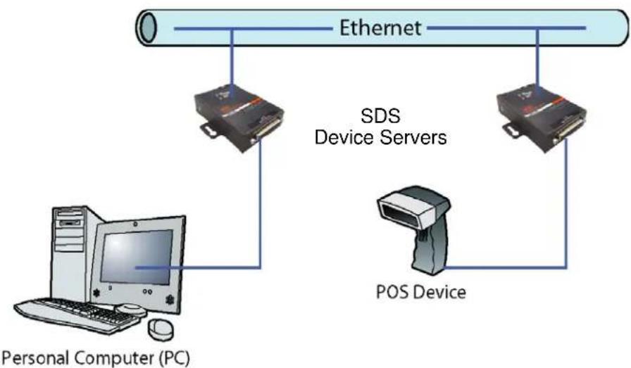
Using a method called serial tunneling, the SDS encapsulates serial data into packets and transports them over Ethernet. Using two SDS units, connected by a network, virtual serial connections can extend across a facility or around the world.
Figure 2-1. Serial Tunneling Example
flowchart
graph TD
    A["Ethernet"] --> B["SDS Device Servers"]
    A --> C["POS Device"]
    B --> D["Personal Computer (PC)"]
    C --> D
    style A fill:#f9f,stroke:#333
    style B fill:#ccf,stroke:#333
    style C fill:#cfc,stroke:#333
    style D fill:#fcc,stroke:#333
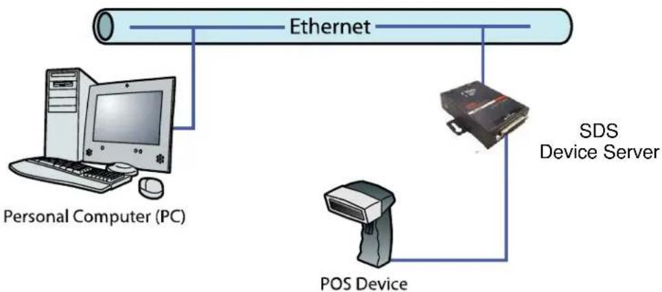
The Com Port Redirector software included on the product CD simplifies the integration process by extending the functionality of COM-port-based Windows™ applications. Virtual COM ports, mapped to remote device servers on the network, can replace direct serial connections.
Figure 2-2. Direct TCP/IP or Redirector Configuration
flowchart
graph TD
    A["Ethernet"] --> B["Personal Computer (PC)"]
    A --> C["SDS Device Server"]
    A --> D["POS Device"]
Note: For step-by-step instructions on configuring the SDS for serial tunneling or for use with the Com Port Redirector, see SDS Configuration Tutorials on the Lantronix web site: www.lantronix.com/support.
Protocol Support
The SDS uses the Internet Protocol (IP) for network communications and the Transmission Control Protocol (TCP) to assure that no data is lost or duplicated and that everything sent to the connection arrives correctly at the target.
Supported protocols include:
- ARP, UDP, TCP, ICMP, Telnet, TFTP, AutoIP, DHCP, HTTP, and SNMP for network communications.
◆ TCP, UDP, and Telnet for connections to the serial port.
◆ TFTP for firmware updates.
◆ IP for addressing, routing, and data block handling over the network.
◆ User Datagram Protocol (UDP) for typical datagram applications in which devices interact with other devices without a point-to-point connection.
Additional Features
Modem Emulation: In modem emulation mode, the SDS can replace dial-up modems. The unit accepts modem AT commands on the serial port and then establishes a network connection to the end device. This arrangement leverages network connections and bandwidth to eliminate dedicated modems and phone lines.
Built-in Web Server: The SDS includes a built-in web server for configuring the unit and displaying operating and troubleshooting information on the attached links to online support.
Configuration Methods
After installation, the SDS requires configuration. For the unit to operate correctly on a network, it must have a unique IP address on the network. There are three basic methods for logging into the SDS and assigning IP addresses and other configurable settings:
DeviceInstaller: Configure the IP address and other network settings on the SDS using a Graphical User Interface (GUI) on a PC attached to a network. (See Assigning the IP Address: DeviceInstaller )
Web-Manager: Through a web browser, configure the SDS settings using the Lantronix Web-Manager. (See 4: Configuration Using Web-Manager.)
Serial and Telnet Ports: Use Setup Mode, a command line interface. There are two approaches to accessing Setup Mode: making a Telnet connection to the network port (9999) or connecting a terminal (or a PC running a terminal emulation program) to the unit's serial port. (See 5: Configuration via Telnet or Serial Port (Setup Mode).
Product Information Label
The product information label on the underside of the unit contains the following information about your specific unit:
Bar code
Serial number
Product ID (name)
Product description
◆ Hardware address (also referred to as the Ethernet or MAC address)
The first three bytes of the hardware address are fixed and read 00-20-4A, identifying the unit as a Lantronix product. The fourth, fifth, and sixth bytes are unique numbers assigned to each unit.
Figure 2-3. Sample Hardware Address
00-20-4A-14-01-18 or 00:20:4A:14:01:18
3: Getting Started
This chapter describes how to get your SDS up and running in the shortest possible time.
Package Contents
Verify and inspect the contents of the SDS1101/2101 package using the following list. If any item is missing or damaged, contact your place of purchase immediately.
◆ SDS1101 or SDS2101
Power supply
◆ CD with documentation and software utilities
◆ Fastening kit
Quick Start Guide
- Six-foot DB9F-to-DB25M modem cable (SDS1101) or DB9F to DB9F Null Modem Cable (SDS2101)
Installing the SDS
Figure 3-1. SDS1101 Connected to Serial Device and Network
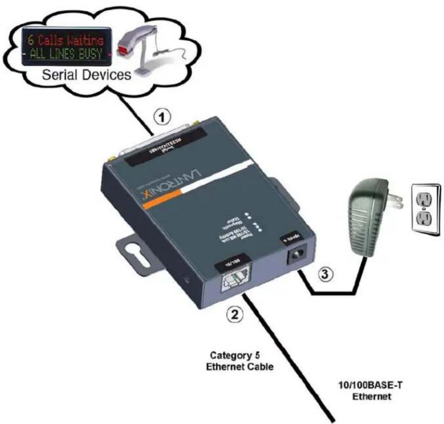
To install the unit:
Complete the following steps in order. Refer to the numbers in the figure above.
Note: See the sections that follow for details about connectors and pinouts.
- Connect a serial device to your unit.
- Connect an Ethernet cable to the RJ45 port.
- Supply power to your unit using the power supply that was included in the packaging.
Note: The required input voltage is 9-30 VDC (center +) or 10-24 VAC (1.5W maximum power required).
- Supply power to the serial device.
Note: If you encounter a problem, please see LEDs for diagnostic information.
Required Information
Before configuring the SDS, have the following information available:
Hardware Address
Take note of the unit's hardware address (also known as the Ethernet or MAC address). It is on the product label, in the format: 00-20-4a-XX-XX-XX, where the XXs are unique numbers assigned to the product (see Product Information Label).
Hardware Address: 00-20-4a-____ - ____ - ____
IP Address
The SDS must have a unique IP address on your network. This address references the specific unit. By default, the unit is DHCP-enabled and automatically assigned an IP address on DHCP-enabled networks. If you are assigning a static IP address, the systems administrator generally provides the IP address, subnet mask, and gateway.
Note: The factory default IP address is 0.0.0.0 to enable DHCP, BOOTP, and AutoIP. When the units boots, it sends a DHCP broadcast to try and get an IP address. If it receives no reply from a DHCP server, the SDS tries BOOTP. If the SDS does not receive a response from BOOTP, it reverts to an AutoIP address.
IP Address: ____ ____ ____ ____
Subnet Mask: ____ ____ ____ ____
Gateway: ____ ____ ____ ____
You have several options for assigning an IP address and related network settings to your unit. This chapter provides information about using the Devicelnstaller (graphical user interface) and serial port login (command line interface) methods.
Note: For information about other methods of assigning the IP address, such as DHCP, AutoIP, ARP, and Telnet, see Alternative Ways to Assign an IP Address.
Assigning the IP Address: DeviceInstaller
This chapter covers the steps for getting the SDS1101/2101 device server online and for viewing its current configuration.
Note: DeviceInstaller online Help provides more detailed information on using DeviceInstaller.
Installing Devicelnstaller
To use the DeviceInstaller utility, first install it from the product CD.
- Insert the product CD into your CD-ROM drive. The Lantronix DeviceInstaller window displays.
- If the CD does not launch automatically:
a) Click the Start button on the Task Bar and select Run.
b) Enter your CD drive letter, colon, backslash, Launch.exe (e.g., D:\Launch.exe).
- Click the DeviceInstaller button.
- Respond to the installation wizard prompts.
Assigning an IP Address
The unit's IP address must be configured before it can work correctly on a network. The unit's IP address is normally set to 0.0.0.0 at the factory. The hardware address is on the product label. The unit is DHCP enabled as the default.
To assign an IP address manually:
- Click Start→Programs → Lantronix→DeviceInstaller→DeviceInstaller. If your PC has more than one network adapter, a message displays. Select an adapter and click OK.
Note: If the unit already has an IP address (e.g., DHCP has assigned an
IP address), click the Search icon Search and select the unit from the list of Lantronix device servers on the local network.
- Click the Assign IP icon AssignIP.
- If prompted, enter the hardware address (on the product label) and click Next.
- Select Assign a specific IP address and click Next.
- Enter the IP address. The Subnet mask displays automatically based on the IP address; if desired, you may change it. On a local network, you can leave the Default gateway blank (all zeros). Click Next.
-
Click the Assign button and wait several seconds until a confirmation message displays. Click Finish.
-
Select the device from the main window list and select Ping from the Tools menu. The Ping Device dialog box shows the IP address of the selected unit.
-
From the Tools menu, click the Ping button. The results display in the Status window. Click the Clear Status button to clear the window so you can ping the device again.
Note: If you do not receive "Reply" messages, make sure the unit is attached to the network properly and the IP address assigned is valid for the particular network segment you are working with. If you are not sure, check with your systems administrator.
- Click the Close button to close the dialog box and return to the main window.
Adding the Unit to the Manage List
Now add the unit to the list of similar Lantronix devices on the network so you can manage and configure it. To perform this step, click the Search icon

DeviceInstaller locates the unit and adds it to the list. Now you can manage (configure) the unit so it works with the serial device on the network.
Accessing the SDS1101/2101 Using Devicelnstaller
-
Click Start→Programs → Lantronix→DeviceInstaller→DeviceInstaller.
-
Click the SDS folder. The list of available Lantronix SDS1101 & SDS2101 devices displays.
-
Expand the list of SDS1101s or SDS2101s by clicking the + symbol next to the SDS1101 or SDS2101 icon. Select the SDS unit by clicking on its IP address to view its configuration.
Viewing the Current Configuration
DeviceInstaller provides a view of the unit's configuration.
To view the unit's current settings:
-
Follow the instructions above to locate the SDS1101 or SDS2101.
-
In the right pane, click the Device Details tab. The current SDS1101/2101 configuration displays:
| Name | Configurable field. A name that identifies the SDS.Double-click the field, type in the value, and press Enter to complete. This name is not visible on other PCs or laptops using DeviceInstaller. |
| Group | Configurable field. A group name to categorize the SDS.Double-click the field, type in the value, and press Enter to complete. This group name is not visible on other PCs or laptops using DeviceInstaller. |
| Comments | Configurable field. Information about the SDS. Double-click the field, type in the value, and press Enter to complete. This description or comment is not visible on other PCs or laptops using DeviceInstaller. |
| Device Family | Non-configurable field. Displays the SDS1101's and SDS2101's device family type as SDS. |
| Type | Non-configurable field. Displays the device type as SDS1101 or SDS2101. |
| ID | Non-configurable field. Displays the SDS's ID embedded within the box. |
| Hardware Address | Non-configurable field. Displays the SDS's hardware (or MAC) address. |
| Firmware Version | Non-configurable field. Displays the firmware currently installed on the SDS. |
| Extended Firmware Version | Non-configurable field. Displays the full version nomenclature of the firmware. |
| Online Status | Non-configurable field. Displays the SDS status as online, offline, unreachable (the SDS is on a different subnet), or busy (the SDS is currently performing a task). |
| IP Address | Non-configurable field. Displays the SDS's current IP address. To change the IP address, see Assigning an IP Address |
| IP Address was obtained | Statically |
| Subnet Mask | Non-configurable field. Displays the SDS's current subnet mask. To change the subnet mask, see Assigning an IP Address. |
| Gateway | Non-configurable field. Displays the SDS's current gateway. To change the gateway, see Assigning an IP Address. |
| Number of COB partitions supported | Non-configurable field. Displays the number of COB partitions supported. |
| Number of Ports | Non-configurable field. Displays the number of ports on the SDS. |
| TCP Keepalive | Non-configurable field. Displays the SDS's TCP keepalive value. The value is in the range 1-65s, and the default setting is 45. |
| Telnet Enabled | Non-configurable field. Permits Telnet sessions. |
| Telnet Port | Non-configurable field. Displays the SDS port for telnet sessions. |
| Web Enabled | Non-configurable field. Permits configuration through Web-Manager. |
| Web Port | Non-configurable field. Displays the SDS port for Web-Manager configuration. |
| Maximum Baud Rate Supported | Non-configurable field. Displays the SDS's maximum baud rate. Note: The SDS1101/2101 may not currently be running at this rate. |
| Firmware Upgradeable | Non-configurable field. Displays True, indicating the SDS's firmware is upgradeable as newer version become available. |
| Supports Configurable Pins | Non-configurable field. Displays False. |
| Supports Email Triggers | Non-configurable field. Displays False. |
| Supports AES Data Stream | Non-configurable field. Displays True. |
| Supports 485 | Non-configurable field. Displays True. The SDS supports the RS-485 protocol. |
| Supports 920K Baudrate | Non-configurable field. Displays False for SDS1101 which supports baud rates up to 230400. Displays True for SDS2101 which supports a baud rate of 921600. |
| Supports HTTP Server | Non-configurable field. Displays True. |
| Supports HTTP Setup | Non-configurable field. Displays True. |
| Supports 230K Baud Rate | Non-configurable field. Displays True. SDS supports a baud rate of 230400. |
| Supports GPIO | Non-configurable field. Displays False. |
Next Step
Now that the SDS has an IP address and other initial settings, you can configure it. You have the following options:
To configure the unit using a Web browser:
- Click the Web Configuration tab.
- Do one of the following:
To view the Web Manager in the current DeviceInstaller window, click the Go button.
To open the Web Manager in a web browser, click the External Browser button.
The Web Manager displays. A user and password dialog box displays.
- By default, no user and password are configured, so just press OK.
- Continue with 4: Configuration Using Web-Manager.
Note: To assign Security settings, you must use the Setup Mode window in a Telnet session.
To configure the unit using a Telnet session:
- Click the Telnet Configuration tab. The Setup Mode window displays.
- Press Enter within 5 seconds.
- Continue with step 4 in 5: Configuration via Telnet or Serial Port (Setup Mode).
Assigning the IP Address: Serial Port Login
To assign the IP address and other network settings using a serial connection:
-
Connect a console terminal or a PC running a terminal emulation program to the unit's serial port. The default serial port settings are 9600 baud, 8 bits, no parity, 1 stop bit, no flow control.
-
To enter Setup Mode, cycle the unit's power (power off and back on). After power-up, the self-test begins and the red Diagnostic LED starts blinking. You have one second to enter three lowercase x characters.
Note: The easiest way to enter Setup Mode is to hold down the x key at the terminal (or emulation) while powering up the unit.
-
Select 0 (Server Configuration) and follow the prompts until you get to IP address.
-
Enter the new IP address, subnet mask, and gateway (if applicable).
-
Do one of the following:
◆ Continue with 5: Configuration via Telnet or Serial Port (Setup Mode).
Select 9 to save and exit Setup Mode. The unit performs a power reset.
4: Configuration Using Web-Manager
You must configure the unit so it can communicate on a network with your serial device. For example, you must set the way the unit will respond to serial and network traffic, how it will handle serial packets, and when to start or close a connection.
The unit's configuration is stored in nonvolatile memory and is retained without power. You can change the configuration at any time. The unit performs a reset after you change and store the configuration.
In this chapter, we describe how to configure the SDS using Web-Manager, Lantronix's browser-based configuration tool. (For information on using Setup Mode, our command line configuration interface, see 5: Configuration via Telnet or Serial Port (Setup Mode).
Note: The examples in this section show a typical device. Your device may have different configuration options.
Accessing SDS1101/2101 Using DeviceInstaller
Note: Make note of the hardware (MAC) address. You will need it to locate the SDS using DeviceInstaller. For more information on the hardware address, see Hardware Address.
Follow the instructions on the product CD to install and run DeviceInstaller.
- Run DeviceInstaller and search for the list of available Lantronix device servers.
- Click the SDS folder. The list of available SDS products displays.
- Expand the list of SDS1101s by clicking the + symbol next to the SDS1101 icon. Likewise, expand the list of SDS2101s by clicking the + symbol next to the SDS2101 icon.
- Select the specific SDS unit by clicking its hardware address.
- In the right pane, click the Web Configuration tab.
- To view the SDS's Web-Manager in the current DeviceInstaller window, click the Go button. To open the Web-Manager in a web browser, click the External Browser button. The Web-Manager displays.
Note: Alternatively, to open Web-Manager, open your web browser and enter the IP address of the SDS.
A user and password dialog box displays. By default, no username and password are configured.
Figure 4-1. Lantronix Web-Manager
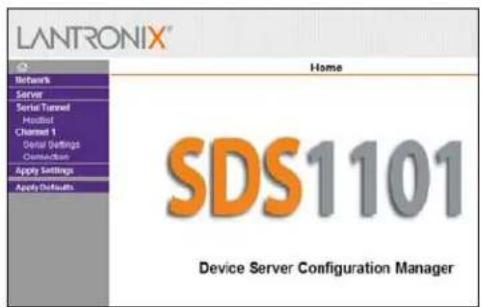
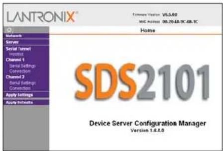
The main menu is in the left pane of the Web-Manager window for both the SDS1101 and SDS2101.
Network Configuration
The unit's network values display when you select Network from the main menu. The following sections describe the configurable parameters on the Network Settings page.
Figure 4-2. Network Settings
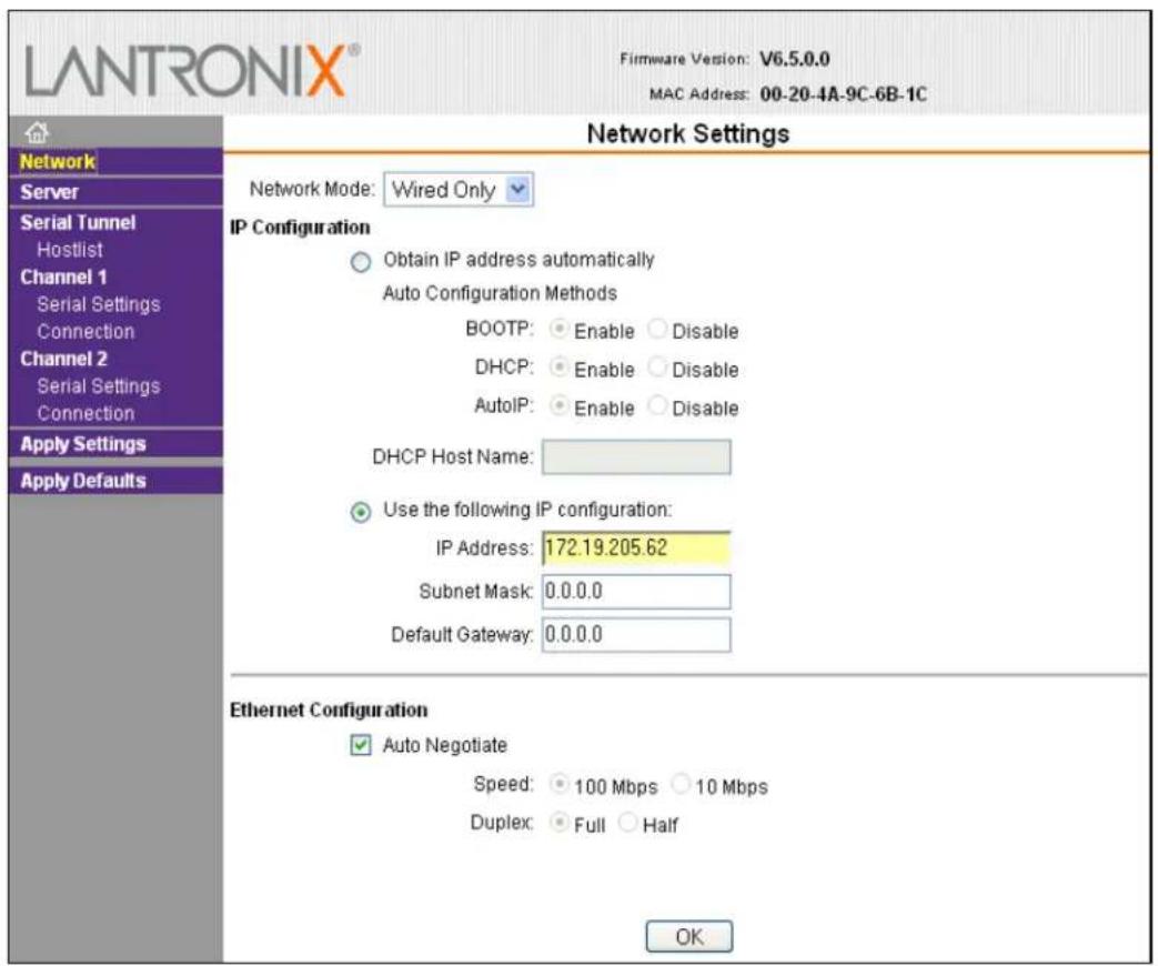
Automatic IP Address Configuration
An IP address can be assigned automatically. You then enter related network settings.
To assign an IP address automatically:
- On the main menu, click Network.
- Select Obtain IP address automatically.
- Enter the following (as necessary):
| BOOTP | Select Enable to permit the Bootstrap Protocol (BOOTP) server to assign the IP address from a pool of addresses automatically. Enable is the default. |
| DHCP | Select Enable to permit the Dynamic Host Configuration Protocol (DHCP) to assign a leased IP address to the SDS unit automatically. Enable is the default. |
| AutoIP | Select Enable to permit the SDS to generate an IP in the 169.254.x.x address range with a Class B subnet. Enable is the default. |
| DHCP Host Name | Enter the name of the host on the network providing the IP address. |
Note: Disabling BOOTP, DHCP, and AutoIP (all three checkboxes) is not advised as the only available IP assignment method will then be ARP or serial port.
- When you are finished, click the OK button.
- On the main menu, click Apply Settings.
Static IP Address Configuration
You can manually assign an IP address to the unit and enter related network settings.
To assign an IP address manually:
- On the main menu, click Network.
- Select Use the following IP configuration.
- Enter the following (as necessary):
| IP Address | If DHCP is not used to assign IP addresses, enter it manually in decimal-dot notation. The IP address must be set to a unique value in the network. |
| Subnet Mask | A subnet mask defines the number of bits taken from the IP address that are assigned for the host part. |
| Default Gateway | The gateway address, or router, allows communication to other LAN segments. The gateway address should be the IP address of the router connected to the same LAN segment as the unit. The gateway address must be within the local network. |
- When you are finished, click the OK button.
- On the main menu, click Apply Settings.
Ethernet Configuration
You must specify the speed and direction of data transmission.
To specify how data will be transmitted:
- On the main menu, click Network.
- Enter the following (as necessary):
| Auto Negotiate | With this option, the Ethernet port auto-negotiates the speed and duplex with the hardware endpoint to which it is connected. This is the default.If this option is not selected, complete the fields that become available:Speed:The speed of data transmission. The default setting is 100 Mbps.Duplex:The direction of data transmission. The default setting is Full. |
- When you are finished, click the OK button.
- On the main menu, click Apply Settings.
Server Configuration
The unit's server values display when you select Server from the main menu. The following sections describe the configurable parameters on the Server Settings page.
Figure 4-3. Server Settings
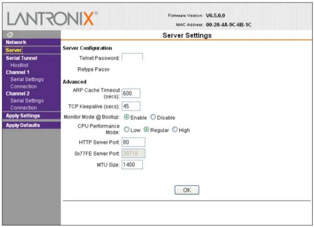
To configure the SDS's device server settings:
- On the main menu, click Server.
- Configure or modify the following fields:
Server Configuration
| Telnet Password | Enter the password required for Telnet access. |
| Retype Password | Re-enter the password required for Telnet access. |
Advanced
| ARP Cache Timeout (secs) | When the unit communicates with another device on the network, it adds an entry into its ARP table. ARP Cache timeout defines the number of seconds (1-600) before it refreshes this table. The default setting is 600. |
| TCP Keepalive (secs) | TCP Keepalive time defines how many seconds the unit waits during an inactive connection before checking its status. If the unit does not receive a response, it drops that connection.Enter a value between 0 and 60 seconds. 0 disables keepalive. The default setting is 45. |
| Monitor Mode @ Bootup | Select Disable to disable entry into the monitor mode using the yyy or xx1 key sequence at startup. This field prevents the unit from entering monitor mode by interpreting the stream of characters that are received during the device server's initialization at startup. The default setting is Enable. |
| CPU Performance Mode (SDS2101 Only) | Select the SDS2101's performance mode. Higher performance settings require more energy.Low is 26 Mhz.Regular is 48 Mhz;High is 88 Mhz. The default is Regular. |
| HTTP Server Port | This option allows the configuration of the web server port number. The valid range is 1-65535. The default setting is 80. |
| MTU Size | The Maximum Transmission Unit (MTU) is the largest physical packet size a network can transmit for TCP and UDP. Enter between 512 and 1400 bytes. The default setting is 1400 bytes. |
- When you are finished, click the OK button.
- On the main menu, click Apply Settings.
Host List Configuration
The SDS scrolls through the host list until it connects to a device listed in the host list table. After a successful connection, the unit stops trying to connect to any others. If this connection fails, the unit continues to scroll through the table until the next successful connection.
The host list supports a minimum of 1 and a maximum of 12 entries. Each entry contains an IP address and a port number.
Note: The host list is disabled for Manual and Modem Mode. The unit does not accept a data connection from a remote device when the hostlist option is enabled.
To configure the host list:
- On the main menu, click Hostlist.
Figure 4-4. Hostlist Settings
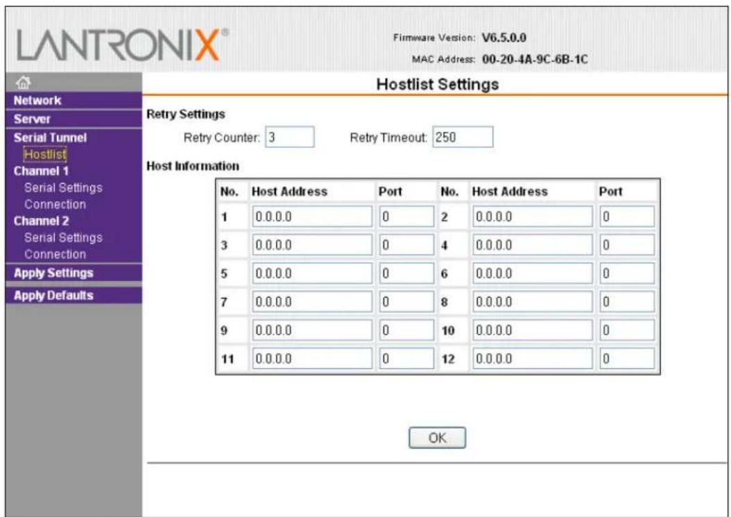
- Enter or modify the following fields:
Retry Settings
| Retry Counter | Enter the value for the number of times the SDS should attempt to retry connecting to the host list. The default setting is 3. |
| Retry Timeout | Enter the duration (in seconds) the SDS should abandon attempting a connection to the host list. The default setting is 250. |
Host Information
| Host Address | Enter or modify the host's IP address. |
| Port Enter the target port number. | |
- When you are finished, click the OK button.
- On the main menu, click Apply Settings.
Channel 1 & Channel 2 (SDS2101 only) Configuration
The Channel configuration defines how the serial port responds to network and serial communication.
Serial Settings
To configure the channel's serial settings:
- On the main menu, click Serial Settings (under Channel 1) to display the Serial Settings window.
Figure 4-5. Channel Serial Settings
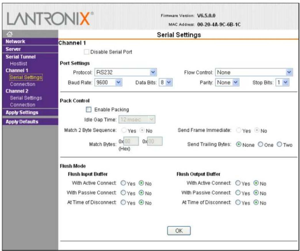
- In the available fields, enter the following information:
Channel 1
| Disable Serial Port | When selected, disables communication through the serial port. The serial port is enabled by default.Note: This feature is not available on single port device servers. |
Port Settings
| Protocol | From the drop-down menu, select the protocol type for the selected channel. The default setting is RS232. |
| Flow Control | Flow control manages data flow between devices in a network to ensure it is processed efficiently. Too much data arriving before a device is prepared to manage it causes lost or retransmitted data. None is the default. |
| Baud Rate | The unit and attached serial device, such as a modem, must agree on a speed or baud rate to use for the serial connection. Valid baud rates are 300, 600, 1200, 2400, 4800, 9600 (default), 19200, 38400, 57600, 115200, and 230400 baud. The SDS2101 also supports 460800 and 921600 baud. Thedefault setting is 9600. |
| Data Bits | Indicates the number of bits in a transmitted data package.The default setting is 8. |
| Parity | Checks for the parity bit. The default setting is None. |
| Stop Bits | The stop bit follows the data and parity bits in serial communication. It indicates the end of transmission. The default setting is 1. |
Pack Control
| Enable Packing | Select to enable packing on the SDS.Two firmware-selectable packing algorithms define how and when packets are sent to the network.The standard algorithm is optimized for applications in which the unit is used in a local environment, allowing for very small delays for single characters, while keeping the packet count low.The alternate packing algorithm minimizes the packet count on the network and is especially useful in applications in a routed Wide Area Network (WAN). Adjusting parameters in this mode can economize the network data stream.Disabled by default. |
| Idle Gap Time | Select the maximum time for inactivity. The default time is 12 milliseconds. |
| Match 2 Byte Sequence Use | to indicate the end of a series of data to be sent as one group. The sequence must occur sequentially to indicate end of the data collection to the SDS. The default setting is No. |
| Match Bytes | Use to indicate the end of a series of data to be sent as one group. Set this value to 00 if specific functions are not needed. |
| Send Frame Only After the | detection of the byte sequence, indicates whether to send the data frame or the entire buffer. Select Yes to send only the data frame. The default setting is No. |
| Send Trailing Bytes | Select the number of bytes to send after the end-of-sequence characters. The default setting is None. |
Flush Input Buffer (Serial to Network)
| With Active Connect | Select Yes to clear the input buffer with a connection that is initiated from the device to the network. The default setting is No. |
| With Passive Connect | Select Yes to clear the input buffer with a connection initiated from the network to the device. The default setting is No. |
| At Time of Disconnect | Select Yes to clear the input buffer when the network connection to or from the device is disconnected. The default setting is No. |
Flush Output Buffer (Network to Serial)
| With Active Connect | Select Yes to clear the output buffer with a connection that is initiated from the device to the network. The default setting is No. |
| With Passive Connect Select | Yes to clear the output buffer with a connection initiated from the network to the device. The default setting is No. |
| At Time of Disconnect | Select Yes to clear the output buffer when the network connection to or from the device is disconnected. The default setting is No. |
-
When you are finished, click the OK button.
-
On the main menu, click Apply Settings.
Connection Settings - TCP
To configure a channel's TCP settings:
- On the main menu, click Connection. The Connection Settings window for the channel displays.
Figure 4-6. TCP Connection Settings
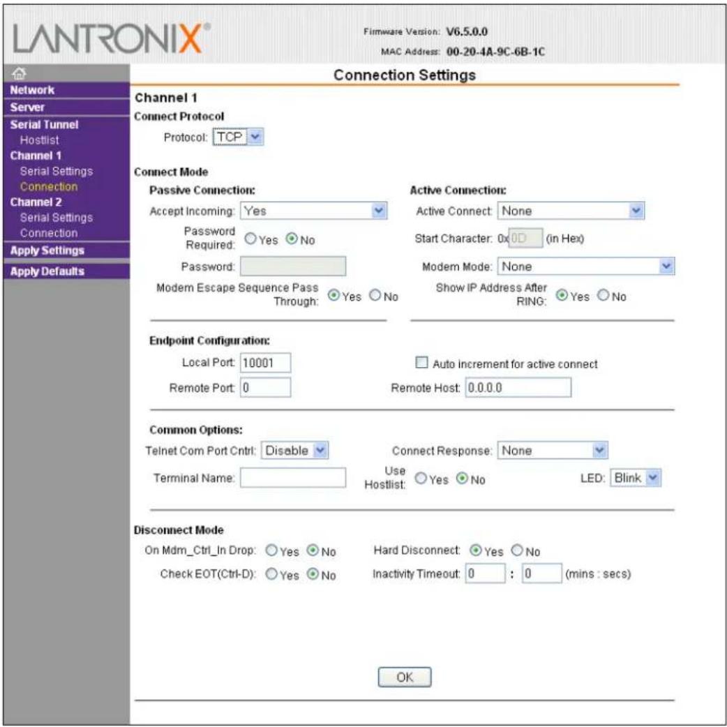
- In the available fields, enter or modify the following information:
Connect Protocol
| Protocol | From the drop-down menu, select TCP. |
Connect Mode: Passive Connection
| Accept Incoming | Select Yes to accept incoming connections. The default setting is Yes. |
| Password Required | Determines whether a password is required for an incoming passive connection. This field is not available when a password is set for Telnet mode. The default setting is No. |
| Password | If Password Required was set to Yes, enter the password for passive connections. |
| Modem Escape Sequence Pass Through | Disable or enable the unit's ability to send the escape sequence. The default is Y (Yes) (send the escape sequence). |
Connect Mode: Active Connection
| Active Connect | Select None (default) to disable Active Connect. Otherwise, indicate the connection type from the drop-down list:With Any Character: Attempts to connect when any character is received from the serial port.With Active Mdm Ctrl In: Accepts external connection requests only when the Modem Control In input is asserted.With Start Character: Attempts to connect when it receives a specific start character from the serial port. The default start character is carriage return.Manual Connection: Attempts to connect when directed by a command string received from the serial port.Auto Start: Automatically connects to the remote IP address and port after booting up. |
| Start Character | If Active Connect is set to With Start Character, enter the start character in this field. The default setting is 0D. |
| Modem Mode | Indicates the on-screen response type when in Modem Mode (if Modem Mode is enabled). The default setting is None. |
| Show IP Address After Ring | Indicates whether to display the remote IP address upon connection. The default setting is Yes. |
Endpoint Configuration
| Local Port | Enter the local port number. |
| Auto increment for active connect | Select to auto-increment the local port number for new outgoing connections. The range of auto-incremented port numbers is 50,000 to 59,999 and loops back to the beginning when the maximum range is reached. Disabled by default. |
| Remote Port | Enter the remote port number. |
| Remote Host | Enter the IP address of the remote device. |
Common Options
| Telnet Com Port Cntrl | This field is available for configuration only when Active Connect is set to None. Select Enable to permit Telnet communication to the SDS unit. The Telnet Com Port Cntrl feature is used in conjunction with the Com Port Redirector (CPR) utility. (See the CPR online Help for details.) |
| Terminal Name | This field is available for configuration only when Telnet Com Port Cntrl is set to Enable.Use the terminal name for the Telnet terminal type. Enter only one name. When this option is enabled, the unit also reacts to the end of record (EOR) and binary options, which can be used for applications such as terminal emulation to IBM hosts. |
| Connect Response A single character is transmitted to the serial port when there is a change in connection state. The default setting is None. | |
| Use Hostlist | If this option is set to True, the device server scrolls through the host list until it connects to a device listed in the host list table. Once it connects, the unit stops trying to connect to any others. If this connection fails, the unit continues to scroll through the table until it connects to another IP in the host list.The host list is disabled for Manual Mode and for Modem Mode. The unit will not accept a data connection from a remote device when the host list option is enabled. |
| LED | Select Blink for the status LEDs to blink upon connection, or select None for no LED output. The default setting is Blink. |
Disconnect Mode
| On Mdm_Ctrl_In Drop | Set to Yes for the network connection to or from the serial port to disconnect (drop) when Modem Control In (DSR for SDS1101) transitions from a high state to a low state. The default setting is No. |
| Hard Disconnect | When set to Yes, the TCP connection closes even if the remote site does not acknowledge the disconnect request. |
| With EOT | Select Yes to drop the connection when Ctrl-D or Hex 04 is detected. Both Telnet Com Port Cntrl and Check EOT (Ctrl+ D) must be enabled for Disconnect with EOT to function properly. Ctrl+D is only detected going from the serial port to the network. The default setting is No. |
| Inactivity Timeout | Use this parameter to set an inactivity timeout. The unit drops the connection if there is no activity on the serial line before the set time expires. Enter time in the format mm:ss, where m is the number of minutes and s is the number of seconds. To disable the inactivity timeout, enter 00:00. |
-
When you are finished, click the OK button.
-
On the main menu, click Apply Settings.
Connection Settings - UDP
To configure a channel's UDP settings:
-
On the main menu, click Connection. The Connection Settings window for the selected channel displays.
-
In the available fields, enter or modify the following information:
Figure 4-7. UDP Connection Settings
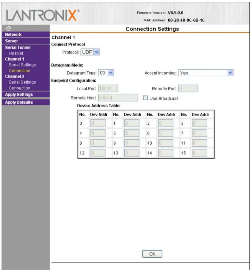
Connect Protocol
| Protocol | Select UDP from the drop-down menu. |
Datagram Mode
| Datagram Type Configures | the remote IP or network broadcast address and the remote port. Enter 01 for directed or broadcast UDP. The default setting is 00. |
| Accept Incoming | Select Yes to accept incoming UDP datagrams. The default setting is Yes. |
Endpoint Configuration
| Local Port | Enter the local port number. |
| Remote Port | Enter the port number of the remote device. |
| Remote Host | Enter the IP address of the remote device. |
| Use Broadcast | Select to broadcast the UDP datagram. Datagrams of type 01 can be sent as a broadcast by enabling this option. The default is not to broadcast.Note:Datagrams are sent as subnet-directed broadcasts. |
| Device Address Table | The table is enabled when Datagram Type is set to FD. Enter values between 1 and 255 to identify units on the local network of device servers.Note:Lantronix Tech Support supports Datagram type 01. Datagram Type FD is for OEM use. |
- When you are finished, click the OK button.
- On the main menu, click Apply Settings.
Apply Settings
- To save and apply the configuration changes to the device server, click the Apply Settings button.
Note: Clicking OK on each page does not change the configuration on the device. OK tells the SDS what changes to use; Apply Settings makes the changes permanent and reboots the SDS.
Apply Factory Defaults
- Click the Apply Defaults button to set the device server back to the default settings. For details see Default Settings (Option 7).
- Click Yes to set factory settings, or click No to cancel.
5: Configuration via Telnet or Serial Port (Setup Mode)
You must configure the unit so it can communicate on a network with your serial device. As an alternative to using a web browser, as described in the previous chapter, you can use the following procedures remotely or locally:
Use a Telnet connection to configure the unit over the network.
Use a terminal or terminal emulation program to access the serial port locally.
The series of prompts at which you enter configuration settings is called Setup Mode.
Note: Detailed information about other setup methods is available from your Lantronix Sales Associate.
The unit's configuration is stored in nonvolatile memory and is retained without power. You can change the configuration at any time. The unit performs a reset after the configuration has been changed and stored.
This chapter tells you how to access Setup Mode and the general procedure for using it. To complete the configuration, continue with 6: Setup Mode: Server Configuration, 7: Setup Mode: Channel Configuration, and 8: Setup Mode: Advanced Settings.
Note: The menus in the configuration chapters show a typical device. Your device may have different configuration options.
Accessing Setup Mode
Telnet Connection
To configure the unit over the network, establish a Telnet connection to port 9999.
Note: You can also use Devicelnstaller to access Telnet. Select the device from the main window list, and click the Telnet Configuration tab. Skip steps 1 and 2.
To establish a Telnet connection:
- From the Windows Start menu, click Run and type the following command, where x.x.x.x is the IP address, and 9999 is the unit's fixed network configuration port number:
Windows: telnet x.x.x.x 9999 UNIX: telnet x.x.x.x 9999
- Click OK. The following information displays.
Figure 5-1. MAC Address
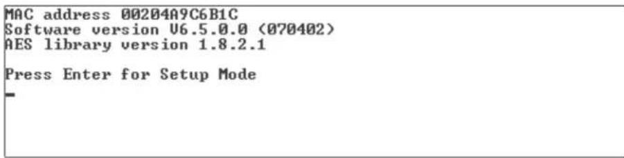
- To enter Setup Mode, press Enter within 5 seconds. The configuration settings display, followed by the Change Setup menu.
Figure 5-2. Setup Menu Options
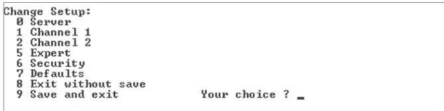
- Select an option on the menu by entering the number of the option in the Your choice ? field and pressing Enter.
- To enter a value for a parameter, type the value and press Enter, or to confirm a current value, just press Enter.
- When you are finished, save the new configuration (option 9). The unit reboots.
Serial Port Connection
To configure the unit through a serial connection:
- Connect a console terminal or PC running a terminal emulation program to your unit's serial port. The default serial port settings are 9600 baud, 8 bits, no parity, 1-stop bit, no flow control.
Note: The SDS always uses the above serial settings at bootup.
- Reset the SDS unit by cycling the unit's power (turning the power off and back on). Immediately upon resetting the device, enter three lowercase x characters (xxx).
Note: The easiest way to enter Setup Mode is to hold down the x key at the terminal (or emulation) while resetting the unit. You must do this within three seconds of resetting the SDS.
At this point, the screen display is the same as when you use a Telnet connection. To continue, go to step 3 in Telnet Connection, above.
Exiting Setup Mode
To exit setup mode, use one of the following two options:
To save all changes and reboot the device, select option 9 Save and exit from the Change Setup menu. All values are stored in nonvolatile memory.
To exit the configuration mode without saving any changes or rebooting. select option 8 Exit without save from the Change Setup menu.
6: Setup Mode: Server Configuration
This chapter explains how to configure the network settings.
Note: Current values display in parentheses.
Server Configuration (Option 0)
The unit's basic network parameters display when you select Server configuration (option 0). The IP Address, Set Gateway IP Address, and Netmask fields display the current values.
Figure 6-1. Network Settings
IP Address : (000) .(000) .(000) .(000)
Set Gateway IP Address (N)
Netmask: Number of Bits for Host Part (0=default) (0)
Change telnet config password (N)
IP Address
If DHCP is not used to assign IP addresses, enter the IP address manually. The IP address must be set to a unique value in the network. Enter each octet and press Enter between each section. The current value displays in parentheses.
IP Address : (000) (000) (000) (000) _
If DHCP is used, the third octet of the IP address sets the BootP/DHCP/AutoIP options. The following table shows the bits you can manually configure to force the SDS to disable AutoIP, DHCP, or BootP. To disable an option, set the appropriate bit.
Table 6-1. BootP/DHCP/AutoIP options
| Options Bit Value | ||
| AutoIP 0 1 | ||
| DHCP | 1 | 2 |
| BootP | 2 | 4 |
For example, if the third octet is 0.0.5.0, the AutoIP and BootP options are disabled; only DHCP is enabled. (The value 5 results from adding the binary equivalents of 0 and 2.) This is the most common setting when using DHCP.
Set Gateway IP Address
The gateway address, or router, allows communication to other LAN segments. The gateway address should be the IP address of the router connected to the same LAN segment as the unit. The gateway address must be within the local network. The
default setting is N (No), meaning the gateway address has not been set. To set the gateway address, type Y and enter the address.
Set Gateway IP Address (N) ? Y
Gateway IP addr (000) (000) (000) (000)_
Netmask: Number of Bits for Host Part
A netmask defines the number of bits taken from the IP address that are assigned for the host part.
Netmask: Number of Bits for Host Part (0=default) (0)_
Note: Class A: 24 bits; Class B: 16 bits; Class C: 8 bits
The unit prompts for the number of host bits to be entered, then calculates the netmask, which appears in standard decimal-dot notation (for example, 255.255.255.0) when the saved parameters display. The default setting is 0.
Table 6-2. Standard IP Network Netmasks
| Network Class | Host Bits | Netmask |
| A | 24 | 255.0.0.0 |
| B | 16 | 255.255.0.0 |
| C 8 255.255.255.0 |
Change Telnet Configuration Password
Setting the Telnet configuration password prevents unauthorized access to the setup menu through a Telnet connection to port 9999 or through web pages. The password must have 4 characters. The default setting is N (No).
Figure 6-2. Change Telnet Configuration Password
Change telnet config password (N) ? _
An enhanced password setting (for Telnet access only) of 16 characters is available under Security Settings (Option 6).
Note: You do not need a password to access the Setup Mode window by a serial connection.
DHCP Name
If a DHCP server has automatically assigned the IP address and network settings, you can discover the unit by using the DeviceInstaller network search feature or Monitor Mode (see 10: Monitor Mode).
Note: When you enter Monitor Mode from the serial port with network connection enabled and issue the NC (Network Communication) command, you see the unit's IP configuration.
There are three methods for assigning DHCP names to the unit.
Default DHCP Name: If you do not change the DHCP name, and you are using an IP of 0.0.0.0, then the DHCP name defaults to XX.XX.XX.XX (XXXXXX is the last 6 digits of the MAC address shown on the label on the bottom/side of the unit). For example, if the MAC address is 00-20-4A-12-34-56, then the default DHCP name is C123456.
- Custom DHCP Name: You can create your own DHCP name. If you are using an IP address of 0.0.0.0, then the last option in Server configuration is Change DHCP device name. This option allows you to change the DHCP name to an alphanumeric name (LTX in our example).
Change DHCP device name (not set) ? (N) Y Enter new DHCP device name : LTX
Numeric DHCP Name: You can change the DHCP name by specifying the last octet of the IP address. When you use this method, the DHCP name is LTXYY where YY is what you chose for the last octet of the IP address. If the IP address you specify is 0.0.0.12, then the DHCP name is LTX12. This method only works with 2 digit numbers (01-99).
7: Setup Mode: Channel Configuration
This chapter explains how to configure the serial port.
Notes:
◆ Current values display in parenthesis.
You must enter some values in hexadecimal notation. (See 0.)
Channel 1 (Option 1) & Channel 2 (Option 2 on SDS2101 only)
Select Channel 1 (option 1) or Channel 2 (option 2 on SDS2101) from the Change Setup menu to define how the serial port responds to network and serial communications. The following sections describe the configurable parameters within the Channel configuration menu.
Figure 7-1. Serial Port Settings
Baudrate (9600) ?
I/F Mode (4C) ?
Flow (00) ?
Port No (10001) ?
ConnectMode (C0) ?
Send '+++' in Modem Mode (Y) ?
Auto increment source port (N) ?
Remote IP Address : (000) .(000) .(000) .(000)
Remote Port (0) ?
DisConnMode (00) ?
FlushMode (00) ?
DisConnTime (00:00) ?:
SendChar 1 (00) ?
SendChar 2 (00) ?
Baudrate
The unit and attached serial device, such as a modem, must agree on a speed or baud rate to use for the serial connection. Valid baud rates are 300, 600, 1200, 2400, 4800, 9600 (default), 19200, 38400, 57600, 115200, and 230400 baud. The SDS2101 also supports 460800 and 921600 baud.
Baudrate (9600) ? _
I/F (Interface) Mode
The Interface (I/F) Mode is a bit-coded byte entered in hexadecimal notation. The default setting is 4C.
I/F Mode (4C) ? _
The following table displays available I/F Mode options:
Note: All bit positions in the table that are blank represent "don't care" bits for that particular option, which can be set to either a 0 or 1 value.
Table 7-1. Interface Mode Options
| I/F Mode Option | 7 | 6 | 5 | 4 | 3 | 2 | 1 | 0 |
| RS-232C ^(1) | 0 | 0 | ||||||
| RS-422/485 4-wire | 0 | 1 | ||||||
| RS-485 2-wire | 1 | 1 | ||||||
| 7 Bit | 1 | 0 | ||||||
| 8 Bit | 1 | 1 | ||||||
| No Parity 0 0 | ||||||||
| Even Parity | 1 | 1 | ||||||
| Odd Parity | 0 | 1 | ||||||
| 1 stop bit 0 1 | ||||||||
| 2 stop bits ^(1) | 1 | 1 |
(1) 2 stop bits are implemented by the software. This might influence performance.
The following table demonstrates how to build some common Interface Mode settings:
Table 7-2. Common Interface Mode Settings
| Common I/F Mode Setting | Binary | Hex |
| RS-232C, 8-bit, No Parity, 1 stop bit | 0100 1100 | 4C |
| RS-232C, 7-bit, Even Parity, 1 stop bit | 0111 1000 | 78 |
| RS-485 2-wire, 8-bit, No Parity, 1 stop bit | 0100 1111 | 4F |
| RS-422, 8-bit, Odd Parity, 1 stop bit | 0101 1101 | 5D |
Flow
Flow control sets the local handshaking method for stopping serial input/output. The default setting is 00.
Flow (00) ? _
Use the following table to select flow control options:
Table 7-3. Flow Control Options
| Flow Control Option | Hex |
| No flow control 00 | |
| XON/XOFF flow control 01 | |
| Hardware handshake with RTS/CTS lines | 02 |
| XON/XOFF pass characters to host | 05 |
Port Number
The setting represents the source port number in TCP connections. It is the number that identifies the channel for remote initiating connections.
Port No (10001) ? _
The default setting for Port 1 is 10001, and for Port 2 is 10002 (SDS2101 only). The range is 1-65535, except for the following reserved port numbers:
Table 7-4. Reserved Port Numbers
| Port Numbers | Reserved for |
| 1 – 1024 | Reserved (well known ports) |
| 9999 Telnet setup | |
| 14000-14009 | Reserved for Redirector |
| 30704 Reserved | (77F0h) |
| 30718 Reserved | (77FEh) |
Warning: We recommend that you not use the reserved port numbers for this setting as incorrect operation may result.
Use Port 0 for the outgoing local port to change with each connection. The port range is 50,000-59,999. Each subsequent connection increments the number by 1 (it wraps back around to 50,000).
Only use this automatic port increment feature to initiate a connection using TCP. Set the port to a non-zero value when the unit is in a passive mode or when using UDP instead of TCP.
Connect Mode
Connect Mode defines how the unit makes a connection, and how it reacts to incoming connections over the network.
ConnectMode (C0) ? _
Enter Connect Mode options in hexadecimal notation. The default setting is C0.
Note: All bit positions in the table that are blank represent "don't care" bits for that particular option, which can be set to either a 0 or 1 value.
Table 7-5. Connect Mode Options
| Connect Mode Option | 7 | 6 | 5 | 4 | 3 | 2 | 1 | 0 |
| a) Incoming Connection | ||||||||
| Never accept incoming | 0 | 0 | 0 | |||||
| Accept with DTR Active | 0 | 1 | 0 | |||||
| Always Accept | 1 | 1 | 0 | |||||
| b) Response | ||||||||
| Nothing (quiet) 0 | ||||||||
| Character response (C=connect, D=disconnect, N=unreachable) | 1 | |||||||
| c) Active Startup | ||||||||
| No active startup | 0 | 0 | 0 | 0 | ||||
| With any character | 0 | 0 | 0 | 1 | ||||
| With DTR Active | 0 | 0 | 1 | 0 | ||||
| With a specific start character | 0 | 0 | 1 | 1 | ||||
| Manual connection | 0 | 1 | 0 | 0 | ||||
| Autostart | 0 | 1 | 0 | 1 | ||||
| Hostlist 0 0 1 0 | ||||||||
| d) Datagram Type | ||||||||
| Directed UDP 1 1 0 0 | ||||||||
| e) Modem Mode | ||||||||
| No Echo | 0 | 0 | 1 | 1 | ||||
| Data Echo & Modem Response (Numeric) | 0 | 1 | 1 | 1 | 1 | |||
| Data Echo & Modem Response (Verbose) | 0 | 1 | 1 | 1 | 0 | |||
| Modem Response Only (Numeric) | 0 | 0 | 1 | 1 | 1 | 1 | ||
| Modem Response Only (Verbose) | 0 | 0 | 1 | 1 | 1 | 0 | ||
a) Incoming Connection
| Never Accept Incoming | Rejects all external connection attempts. |
| Accept with DTR Active | Accepts external connection requests only when the DTR input is asserted. Cannot be used with Modem Mode. |
| Always Accept | Accepts any incoming connection when a connection is notalready established. Default setting. |
b) Response
| Character Response | A single character is transmitted to the serial port when there is a change in connection state:C = connected, D = disconnected, N = host unreachable.This option is overridden when the Active Start Modem Mode or Active Start Host List is in effect. Default setting is Nothing (quiet). |
c) Active Startup
| No Active Startup | Does not attempt to initiate a connection under any circumstance. Default setting. |
| With Any Character | Attempts to connect when any character is received from the serial port. |
| With DTR Active | Attempts to connect when the DTR input changes from not asserted to asserted. |
| With a Specific Start Character | Attempts to connect when it receives a specific start character from the serial port. The default start character is carriage return. |
| Manual Connection | Attempts to connect when directed by a command string received from the serial port. The first character of the command string must be a C (ASCII 0x43), and the last character must be either a carriage return (ASCII 0x0D) or a line feed (0x0A). No blanks or space characters may be in the command string. Between the first and last command string characters must be a full or partial destination IP address and may be a destination port number.The IP address must be in standard decimal-dot notation and may be a partial address, representing the least significant 1, 2, or 3 bytes of the remote IP address. The period is required between each pair of IP address numbers.If present, the port number must follow the IP address, must be presented as a decimal number in the range 1-65535, and must be preceded by a forward slash (ASCII 0x2F). The slash separates the IP address and the port number. If you omit the port number from a command string, the internally stored remote port number starts a connection.If a partial IP address is presented in a command string, it is interpreted to be the least significant bytes of the IP address and uses the internally stored remote IP address to provide the most significant bytes of the IP address. If the IP address entered is 0.0.0.0/0, the device server enters Monitor Mode.For example, if the remote IP address already configured in the unit is 129.1.2.3, then an example command string would be C3/7. (This would connect to 129.1.2.3 and port 7.) You may also use a different ending for the connection string. For example, C50.1/23 would connect you to 129.1.50.1 and port 23. |
Table 7-6. Manual Connection Address Example
| Command String | Result if remote IP is 129.1.2.3 and remote port is 1234 |
| C121.2.4.5/1 | Complete override; connection is started with host 121.2.4.5, port 1. |
| C5 | Connects to 129.1.2.5, port 1234. |
| C28.10/12 | Connects to 129.1.28.10, port 12. |
C0.0.0.0/0 Enters Monitor Mode.
| Autostart (Automatic Connection) | If you enable Autostart, the unit automatically connects to the remote IP address and remote port specified when the firmware starts. |
| Hostlist | If you enable this option, the device server scrolls through the hostlist until it connects to a device listed in the hostlist table.Once it connects, the unit stops trying to connect to any others. If this connection fails, the unit continues to scroll through the table until it is able to connect to another IP in the hostlist.Hostlist supports a minimum of 1 and a maximum of 12 entries. Each entry contains the IP address and the port number.The hostlist is disabled for Manual and Modem Modes. The unit does not accept a data connection from a remote device when the hostlist option is enabled. |
Figure 7-2. Hostlist Option
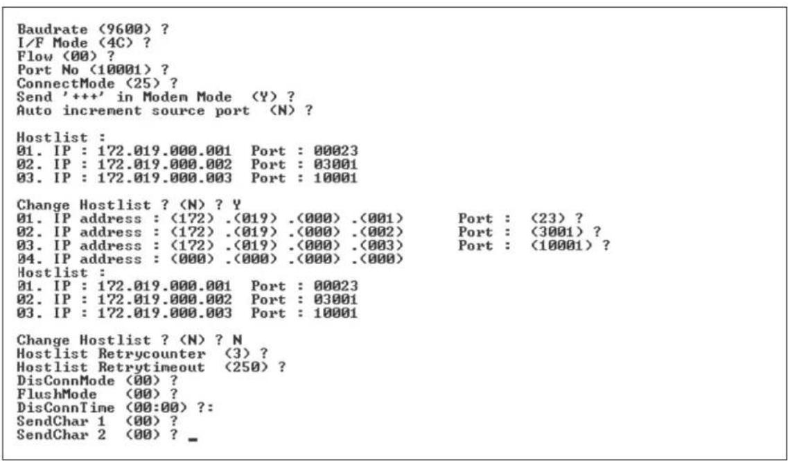
To enable the hostlist:
- Enter a Connect Mode of 0x20 (2X), where X is any digit. The menu shows you a list of current entries already defined in the product.
- To delete, modify, or add an entry, select Yes. If you enter an IP address of 0.0.0.0, that entry and all others after it are deleted.
- After completing the hostlist, repeat the previous step if necessary to edit the hostlist again.
- For Retrycounter, enter the number of times the Lantronix unit should try to make a good network connection to a hostlist entry that it has successfully ARPed. The range is 1-15, with the default set to 3.
- For Retrytimeout, enter the number of seconds the unit should wait before failing an attempted connection. The time is stored as units of milliseconds in the range of 10-65535. The default setting is 250.
d) Datagram Type
| Directed UDP | When selecting this option, you are prompted for the Datagram type.Enter 01 for directed or broadcast UDP. Datagrams of type 01 can be sent as a broadcast by enabling theSend as Broadcastoption. The default is not to broadcast.Note:Datagrams are sent as subnet-directed broadcasts.When the UDP option is in effect, the unit never attempts to initiate a TCP connection because it uses UDP datagrams to send and receive data. |
e) Modem Mode
In Modem (Emulation) Mode, the unit presents a modem interface to the attached serial device. It accepts AT-style modem commands and handles the modem signals correctly.
Normally, there is a modem connected to a local PC and a modem connected to a remote machine. A user must dial from the local PC to the remote machine, accumulating phone charges for each connection. Modem Mode allows you to replace modems with SDSs, and to use an Ethernet connection instead of a phone call. By not having to change communications applications, you avoid potentially expensive phone calls.
To select Modem Mode, set the Connect Mode to C6 (no echo), D6 (echo with full verbose), D7 (echo with numeric response), CF (modem responses only, numeric response), or CE (modem responses only, full verbose).
Note: If the unit is in Modem Mode, and the serial port is idle, the unit can still accept network TCP connections to the serial port if Connect Mode is set to C6 (no echo), D6 (echo with full verbose), D7 (echo with numeric response, CF (modem responses only, numeric response), or CE (modem responses only, full verbose).
| Without Echo | In Modem Mode, echo refers to the echo of all of the characters entered in command mode; it does not mean to echo data that istransferred. Quiet Mode (without echo) refers to the modem not sending an answer to the commands received (or displaying what was typed). |
| Data Echo & Modem Response | Full Verbose: The unit echoes modem commands and responds to a command with a message string shown in the table below.Numeric Response: The unit echoes modem commands and responds to a command with a numeric response. |
| Modem Responses Only | Full Verbose: The unit does not echo modem commands and responds to a command with a message string shown in the table below.Numeric Response: The unit does not echo modem commands and responds to a command with a numeric response. |
Table 7-7. Modem Mode Messages
| Message | Meaning |
| Full Verbose | |
| OK | Command was executed without error. |
| CONNECT | A network connection has been established. |
| NO CARRIER | A network connection has been closed. |
| RING n.n.n.n. | A remote device, having IP address n.n.n.n, is connecting to this device. |
| Numeric Response | |
| 0 OK | |
| 1 | Connected |
| 2 | Ring |
| 3 No Carrier | |
| 4 | Error |
Received commands must begin with the two-character sequence AT and be terminated with a carriage return character.
The unit ignores any character sequence received not starting with AT, and only recognizes and processes single AT-style commands. The unit treats compound AT commands as unrecognized commands.
If the Full Verbose option is in effect, the unit responds to an unrecognized command string that is otherwise formatted correctly (begins with AT and ends with carriage return) with the "OK" message and takes no further action.
If the Numeric Response option is in effect, the unit responds to an unrecognized command string that is otherwise formatted correctly with a "0" message and takes no further action.
When an active connection is in effect, the unit transfers data and does not process commands received from the serial interface.
When a connection is terminated or lost, the unit reverts to command mode.
When an active connection is in effect, the unit terminates the connection if it receives the following sequence from the attached serial device:
◆ No serial data is received for one second.
The character sequence +++ is received, with no more than one second between each two characters.
No serial data is received for one second after the last + character. At this time, the unit responds affirmatively per the selected echo/response mode.
The character string ATH is received, terminated with a carriage return. The unit responds affirmatively according to the selected echo/response mode and drops the network connection. The serial interface reverts to accepting command strings.
If this sequence is not followed, the unit remains in data transfer mode.
Table 7-8. Modem Mode Commands
| Modem Mode Command | Function |
| ATDTx.x.x.x,pppp or ATDTx.x.x.x/pppp | Makes a connection to an IP address (x.x.x.x) and a remote port number (pppp). |
| ATDTx.x.x.x | Makes a connection to an IP address (x.x.x.x) and the remote port number defined within the unit. |
| ATD0.0.0.0 | Forces the unit into Monitor Mode if a remote IP address and port number are defined within the unit. |
| ATD | Forces the unit into Monitor Mode if a remote IP address and port number are not defined within the unit. |
| ATDx.x.x.x | Makes a connection to an IP address (x.x.x.x) and the remote port number defined within the unit. |
| ATH | Hangs up the connection (Entered as +++ATH). |
| ATS0=n | Enables or disables connections from the network going to the serial port.n=0 disables the ability to make a connection from the network to the serial port.n=1-9 enables the ability to make a connection from the network to the serial port.n>1-9 is invalid. |
| ATEn | Enables or disables character echo and responses.n=0 disables character echo and responses.n=1 enables character echo and responses. |
| ATVn | Enables numeric response or full verbose.n=0 enables numeric response.n=1 enables full verbose. |
Note: The unit recognizes these AT commands as single commands such as ATE0 or ATV1; it does not recognize compound commands such as ATE0V.
Send the Escape Sequence (+++) in Modem Mode
Send '+++' in Modem Mode (Y) ? _
Disable or enable the SDS's ability to send the escape sequence. The default setting is Y (Yes) (send the escape sequence).
Show IP addr after 'RING'
Show IP addr after 'RING' <Y> ?
Disable or enable the SDS's ability to show the IP address after RING in Modem Mode. The default is Y (Yes), to show the IP address.
Auto Increment Source Port
Auto increment source port (N) ? _
Y (Yes) auto increment the source port. The SDS increments the port number used with each new connection.
Remote IP Address
This is the destination IP address used with an outgoing connection.
Remote IP Address : (000) (000) (000) (000)_
Note: This option does not display when Hostlist is enabled from the ConnectMode prompt (see Connect Mode for more information).
Remote Port
You must set the remote TCP port number for the unit to make outgoing connections. This parameter defines the port number on the target host to which a connection is attempted.
Remote Port (0) ? _
To connect an ASCII terminal to a host using the unit for login purposes, use the remote port number 23 (Internet standard port number for Telnet services).
Note: This option does not display when Hostlist is enabled from the ConnectMode prompt (see Connect Mode for more information).
DisConnMode
This setting determines the conditions under which the unit will cause a network connection to terminate. The default setting is 00.
DisConnMode (00) ? _
Notes:
In DisConnMode (Disconnect Mode), DTR drop either drops the connection or is ignored.
All bit positions in the table that are blank represent "don't care" bits for that particular option, which can be set to either a 0 or 1 value.
Table 7-9. Disconnect Mode Options
| Disconnect Mode Option | 7 | 6 | 5 | 4 | 3 | 2 | 1 | 0 |
| Disconnect with Modem Control In drop (6) | 1 | |||||||
| Ignore DTR | 0 | |||||||
| Telnet Com Port Cntrl and terminal type setup (1) | 1 | |||||||
| Channel (port) password (2) 1 | ||||||||
| Hard disconnect (3) 0 | ||||||||
| Disable hard disconnect | 1 | |||||||
| State LED off with connection (4) 1 | ||||||||
| Disconnect with EOT (^D) (5) 1 |
(1) The Telnet Com Port Control feature is used in conjunction with Com Port Redirector. The SDS sends the "Terminal Type" upon an outgoing connection.
(2) A password is required for a connection to the serial port from the network.
(3) The TCP connection closes even if the remote site does not acknowledge the disconnection.
(4) When there is a network connection to or from the serial port, the state LED turns off instead of blinking.
(5) When Ctrl+D or Hex 04 is detected, the connection is dropped. Both Telnet Com Port Cntrl and Disconnect with EOT must be enabled for Disconnect with EOT to function properly. Ctrl+D is only detected going from the serial port to the network.
(6) When Modem Control In transitions from a high state to a low state, the network connection to or from the serial port drops.
Flush Mode (Buffer Flushing)
Using this parameter, you can control line handling and network buffers with connection startup and disconnect. The default setting is 00.
FlushMode (00) ? _
You can also select between two different packing algorithms.
Note: All bit positions in the table that are blank represent "don't care" bits for that particular option, which can be set to either a 0 or 1 value.
Table 7-10. Flush Mode Options
| Function | 7 | 6 | 5 | 4 | 3 | 2 | 1 | 0 |
| Input Buffer (Serial to Network) | ||||||||
| Clear with a connection initiated from the device to the network | 1 | |||||||
| Clear with a connection initiated from the network to the device | 1 | |||||||
| Clear when the network connection to or from the device is disconnected | 1 | |||||||
| Output Buffer (Network to Serial) | ||||||||
| Clear with a connection initiated from the device to the network | 1 | |||||||
| Clear with a connection initiated from the network to the device | 1 | |||||||
| Clear when the network connection to or from the device is disconnected | 1 | |||||||
| Alternate Packing Algorithm (Pack Control) | ||||||||
| Enable | 1 | |||||||
Pack Control
The packing algorithms define how and when packets are sent to the network. The standard algorithm is optimized for applications in which the unit is used in a local environment, allowing for very small delays for single characters, while keeping the packet count low. The alternate packing algorithm minimizes the packet count on the network and is especially useful in applications in a routed Wide Area Network (WAN). Adjusting parameters in this mode can economize the network data stream.
Pack control settings are enabled in Flush Mode. Set this value to 00 if you do not need specific functions.
Note: All bit positions in the table that are blank represent "don't care" bits for that particular option, which can be set to either a 0 or 1 value.
Table 7-11. Pack Control Options
| Option | 7 | 6 | 5 | 4 | 3 | 2 | 1 | 0 |
| Packing Interval | ||||||||
| Interval: 12 msec | 0 | 0 | ||||||
| Interval: 52 msec | 0 | 1 | ||||||
| Interval: 250 msec | 1 | 0 | ||||||
| Interval: 5 sec | 1 | 1 | ||||||
| Trailing Characters | ||||||||
| None | 0 | 0 | ||||||
| One | 0 | 1 | ||||||
| Two | 1 | 0 | ||||||
| Send Characters | ||||||||
| 2-Byte Send Character Sequence | 1 | |||||||
| Send Immediately After Send chars | 1 | |||||||
Packing Interval
Packing Interval defines how long the unit should wait before sending accumulated characters. This wait period is between successive network segments containing data. For alternate packing, the default interval is 12 ms.
Trailing Characters
In some applications, CRC, Checksum, or other trailing characters follow the end-of-sequence character; this option helps to adapt frame transmission to the frame boundary. The default setting is 00 (none).
Send Characters
If 2-Byte Send Character Sequence is enabled, the unit interprets the sendchars as a 2-byte sequence; if this option is not enabled, the unit interprets them independently. The default setting is 0 (disabled).
If Send Immediately After Characters is not set, any characters already in the serial buffer are included in the transmission after a "transmit" condition is found. If this option is set, the unit sends immediately after recognizing the transmit condition (sendchar or timeout). The default setting is 0.
Note: A transmission might occur if status information needs to be exchanged or an acknowledgment needs to be sent.
DisConnTime (Inactivity Timeout)
Use this parameter to set an inactivity timeout. The unit drops the connection if there is no activity on the serial line before the set time expires. Enter time in the format mm:ss, where m is the number of minutes and s is the number of seconds.
DisConnTime (00:00) ?:
To disable the inactivity timeout, enter 00:00. Range is 0 (disabled) to 5999 seconds (99 minutes, 59 seconds). Default setting is 0.
Send Characters
Enter up to two characters in hexadecimal representation in sendchar.
SendChar 1 (00) ? _
SendChar 2 (00) ? _
If the unit receives a character on the serial line that matches one of these characters, it sends the character immediately, along with any awaiting characters, to the TCP connection. This action minimizes the response time for specific protocol characters on the serial line (for example, ETX, EOT). Setting the first sendchar to 00
disables the recognition of the characters. Alternatively, the unit can interpret two characters as a sequence (see Pack Control). The default setting is 00.
Telnet Terminal Type
This parameter displays only if you enabled the terminal type option in Disconnect Mode. With this option enabled, you can use the terminal name for the Telnet terminal type. Enter only one name.
With terminal type option enabled, the unit also reacts to the EOR (end of record) and binary options, useful for applications like terminal emulation to IBM hosts.
Channel (Port) Password
This parameter appears only if the channel (port) password option is enabled in Disconnect Mode. With this option enabled, you can set a password on the serial port. The default setting is all 0s.
8: Setup Mode: Advanced Settings
Expert Settings (Option 5)
Note: You can change these settings using Telnet or serial connections, but not all of them are available on the Web-Manager.
Caution: Changing the expert settings can drastically affect the performance and access to the product. These settings should only be changed by an experienced network administrator.
Figure 8-1. Expert Settings
TCP Keepalive : 45s
ARP cache timeout: 600s
CPU performance: Regular
Monitor Mode @ bootup : enabled
HTTP Port Number : 80
MTU Size: 1400
Alternate MAC: disabled
Ethernet connection type: auto-negotiate
This option allows you to change how many seconds the unit waits during a silent connection before attempting to see if the currently connected network device is still on the network. If the unit gets no response, it drops that connection. The default setting is 45.
TCP Keepalive time in s (1s - 65s; 0s=disable): (45)?
ARP Cache timeout in seconds
Whenever the unit communicates with another device on the network, it adds an entry into its ARP table. The ARP Cache timeout option allows you to define how many seconds (1-600) the unit will wait before timing out this table. The default setting is 600.
ARP Cache timeout in s (1s - 600s): (600)? _
CPU Performance (SDS2101 only)
Select the SDS2101's performance mode. Higher performance settings require more energy. Low is 26 Mhz; Regular is 48 Mhz; High is 88 Mhz. The default is Regular.
CPU performance (0=Regular, 1=Low, 2=High): (0)
Disable Monitor Mode at bootup
This option allows you to disable all entries into Monitor Mode during startup, except for the 'xxx' sequence. This prevents entry using yyy, zzz, xx1, and yy1 key
sequences (only during the bootup sequence). The default for Disable Monitor Mode at bootup is N (No). (See 10: Monitor Mode.)
Monitor Mode @ bootup : enabled
HTTP Port Number
This option allows the configuration of the web server port number. The valid range is 1-65535. The default HTTP port number is 80.
HTTP Port Number : (80) ? _
MTU Size
The Maximum Transmission Unit (MTU) is the largest physical packet size a network can transmit for TCP and UDP. Enter between 512 and 1400 bytes. The default setting is 1400 bytes.
MTU Size: (1400) ? _
Enable alternate MAC
If necessary, enable the alternate MAC address (if specified in the OEM setup record). The default setting is N (No).
Enable alternate MAC (N) ? _
Ethernet connection type
The SDS allows for the Ethernet speed and duplex to be manually configured. Enter 0 for auto-negotiation (default). To select the speed and duplex, enter one of the following: 2 (10Mbit/half duplex), 3 (10Mbit/full duplex), 4 (100Mbit/half duplex), or 5 (100Mbit/full duplex).
Ethernet connection type: (0) ? _
Security Settings (Option 6)
You can change security settings by means of Telnet or serial connections only, not on the Web-Manager. We recommend that you set security over the dedicated network or over the serial setup to prevent eavesdropping.
Caution: Disabling both Telnet Setup and Port 77FE will prevent users from accessing the setup menu from the network. Disabling Port 77FE also disables the Web from configuring the device.
Select 6 to configure security settings.
Figure 8-2. Security Settings
Disable SNMP (N) ?
SNMP Community Name (public):
Disable Telnet Setup (N) ?
Disable TFTP Firmware Update (N) ?
Disable Port 77FEh (N) ?
Disable Web Server (N) ?
Disable Web Setup (N) ?
Disable ECHO ports (Y) ?
Enable Encryption (N) ?
Enable Enhanced Password (N) ?
Disable SNMP
This setting allows you to disable the SNMP protocol on the unit for security reasons. The default setting is N (No).
Disable SNMP (N) ?
SNMP Community Name
The SNMP Community Name is a required field for NMS to read or write to a device. Enter a string of 1 to 13 characters. The default setting is public.
SNMP Community Name (public):
The default entry is public. The current value is displayed in parentheses.
Disable Telnet Setup
Note: If you choose to disable this option, keep in mind that disabling both Telnet Setup and Port 77FE will prevent users from accessing the setup menu from the network.
This setting defaults to the N (No) option. The Y (Yes) option disables access to Setup Mode by Telnet (port 9999). It only allows access locally using the web pages and the serial port of the unit.
Disable Telnet Setup (N) ?
Disable TFTP Firmware Update
This setting defaults to the N (No) option. The Y (Yes) option disables the use of TFTP to perform network firmware upgrades. With this option, you can download firmware upgrades over the serial port using Devicelnstaller's Recover Firmware procedure. (See 9: Firmware Upgrades.)
Disable TFTP Firmware Update (N) :
Disable Port 77FE (Hex)
Note: If you choose to disable this option, keep in mind that disabling both Telnet Setup and Port 77FE will prevent users from accessing the setup menu from the network.
Port 77FE is a setting that allows DeviceInstaller, Web-Manager, and custom programs to configure the unit remotely. You may wish to disable this capability for security purposes.
Disable Port 77FEh (N) ?
The default setting is the N (No) option, which enables remote configuration. You can configure the unit by using DeviceInstaller, web pages, Telnet, or serial configuration.
The Y (Yes) option disables remote configuration and web sites.
Disable Web Server
This setting defaults to the N (No) option. The Y (Yes) option disables the web server.
Disable Web Server (N) ?
Disable Web Setup
The Y (Yes) option disables configuration using the Web-Manager. This setting defaults to the N (No) option.
Disable Web Setup (N) ?
Disable ECHO Ports
This setting controls whether port 7 echoes characters it receives. The default setting is Y (Yes), which disables ECHO ports.
Disable ECHO ports (Y) ?
Enable Enhanced Password
This setting defaults to the N (No) option, which allows you to set a 4-character password that protects Setup Mode by means of Telnet and web pages. The Y (Yes) option allows you to set an extended security password of 16-characters for protecting Telnet and Web Page access.
Enable Enhanced Password (N) ?
Enable Encryption
Rijndael is the block cipher algorithm chosen by the National Institute of Science and Technology (NIST) as the Advanced Encryption Standard (AES) to be used by the US government. The SDS supports 128-, 192-, and 256-bit encryption key lengths.
NOTE: Configuring encryption should be done through a local connection to the serial port of the SDS, or via a secured network connection. Initial
configuration information including the encryption key are sent in clear text over the network.
To configure AES encryption on the SDS:
Figure 8-3. Encryption Keys
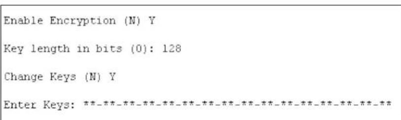
- When prompted to enable encryption, press Y.
- Enter the encryption key length when prompted. The SDS supports 128-, 192-, and 256-bit encryption key lengths.
- When prompted to change keys, press Y.
- At the Enter Keys prompts, enter your encryption key. The encryption keys are entered in hexadecimal. The hexadecimal values are echoed as asterisks to prevent onlookers from seeing the key. Hexadecimal values are 0-9 and A-F.
For a 128-bit key length, enter 32 hexadecimal characters.
For a 192-bit key length, enter 48 hexadecimal characters.
For a 256-bit key length, enter 64 hexadecimal characters
-
Continue pressing Enter until you return to the Change Setup menu.
-
At the Change Setup menu, select option 9 to save and exit.
Encryption only applies to the port selected for data tunneling (default 10001), regardless of whether you are using TCP or UDP.
Generally, one of these situations applies:
◆ Encrypted SDS-to-SDS communication. Be sure to configure both SDS devices with the same encryption key.
Third-party application to SDS-encrypted communication: SDS uses standard AES encryption protocols. To communicate successfully, products and applications on the peer side must use the same protocols and the same encryption key as the SDS. Developers can license the Lantronix Encryption Library suite.
- Lantronix Secure Com Port Redirector provides an encrypted connection from Windows-based applications to the SDS. A 30-day trial version of SCPR is included on the CD.
NOTE: For more information about the Lantronix Encryption Library Suite and SCPR see www.lantronix.com/device-networking/utilities-tools/.
Default Settings (Option 7)
Select 7 to reset the unit's Channel 1 configuration and expert settings to the default settings. The server configuration settings for IP address, gateway IP address, and netmask remain unchanged. The configurable pins' settings also remain unchanged. The specific settings that this option changes are listed below:
Channel 1 Configuration Defaults
| Baudrate | 9600 |
| I/F Mode | 4C (1 stop bit, no parity, 8 bit, RS-232C) |
| Own TCP port number | 10001 |
| Connect Mode | C0 (always accept incoming connection; no active connection startup) |
| Hostlist retry counter | 3 |
| Hostlist retry timeout | 250 (msec) |
| Start character for serial channel 1 | 0x0D (CR) |
| All other parameters 0 |
Channel 2 Configuration Defaults (SDS2101 only)
| Baudrate | 9600 |
| I/F Mode | 4C (1 stop bit, no parity, 8 bit, RS-232C) |
| Own TCP port number 10002 | |
| Connect Mode | C0 (always accept incoming connection; no active connection startup) |
| Hostlist retry counter | 3 |
| Hostlist retry timeout | 250 (msec) |
| Start character for serial channel 2 0x0D | (CR) |
| All other parameters | 0 |
Expert Settings Defaults
| TCP Keepalive time in s | 45 |
| ARP Cache timeout in s | 600 |
| Disable Monitor Mode @ bootup | No |
| HTTP Port Number 80 | |
| (1-65535) | |
| MTU Size (512 – 1400) | 0 (resulting in an operational value of 1400) |
| Enable alternate MAC | No ( for OEM use only) |
| Ethernet Connection Type | 0 (auto-negotiate) |
Security Settings Defaults
| Disable SNMP No | |
| SNMP community name | public |
| Disable Telnet setup | No |
| Disable TFTP Firmware Update No | |
| Disable Port 77FEh | No |
| Disable Web Server | No |
| Disable Web Setup No | |
| Disable ECHO ports | Yes |
| Enable Encryption No | |
| Enable Enhanced Password | No |
9: Firmware Upgrades
Obtaining Firmware
You can obtain the most up-to-date firmware and release notes for the unit from the Lantronix web site (www.lantronix.com) or by using anonymous FTP (ftp.lantronix.com).
Reloading Firmware
There are several ways to update the unit's internal operational code (*.ROM): using Devicelnstaller (the preferred way), using TFTP, or using the serial port. You can also update the unit's internal Web interface (*.COB) using TFTP or Devicelnstaller.
Here are typical names for those files. Check the Lantronix web site for the latest versions and release notes.
Table 9-1. Firmware Files
| ROM File | COB |
| SDS1101_6102.rom SDS1101_webm_1404.cob | |
| SDS2101_6500.rom | SDS2101_webm_1600.cob |
Please refer to the DeviceInstaller online Help for information about reloading firmware using DeviceInstaller. The other methods are discussed below.
Using TFTP: Graphical User Interface
To download new firmware from a computer:
- Use a TFTP client to send a binary file to the unit (*.ROM to upgrade the unit's internal operational code and *.COB to upgrade its internal Web interface).
Note: TFTP requires the .ROM (binary) version of the unit's internal operational code.
- In the TFTP server field, enter the IP address of the unit being upgraded.
- Select Upload operation and Binary format.
- Enter the full path of the firmware file in the Local file name field.
- In the Remote file name field, enter the current internal operational code (D3 for SDS1101 or D4 for SDS2101) or WEB1 for the internal Web interface.
- Click the Upload Now button to transfer the file to the unit.
Figure 9-1. TFTP Window
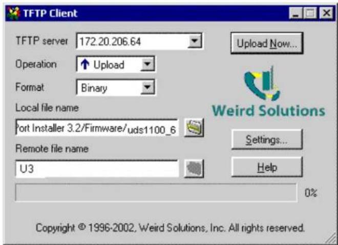
After the firmware has been loaded and stored (approximately 8 seconds to complete) the unit performs a power reset.
Using TFTP: Command Line Interface
To download new firmware from a computer, enter the following from a TFTP command line interface:
tftp -i
The following examples demonstrate the TFTP command sequence to download the .rom file and the .cob file:
SDS1101
tftp -i 192.168.1.111 put SDS1101_6102.rom D3
tftp -i 192.168.1.111 put SDS1101_webm_1404.cob WEB1
SDS2101
tftp -i 192.168.1.121 put SDS2101_6500.rom D4
tftp -i 192.168.1.121 put SDS2101_webm_1600.cob WEB1
Recovering the Firmware Using the Serial Port and DeviceInstaller
If for some reason the firmware is damaged, you can recover the firmware file by using Devicelnstaller to download the *.ROM file over the serial port.
To recover firmware:
-
Start DeviceInstaller. If your PC has more than one network adapter, a message displays. Select an adapter and click OK.
-
From the Tools menu, select Advanced/Recover Firmware. The Serial Port Firmware Upgrade window displays.
- For Port on PC, enter the COM port on the PC that is connected to the serial port of the Lantronix unit.
- For Device Model, be sure the appropriate device (e.g. SDS1101) displays.
- For Firmware File, click the Browse button and go to the location where the firmware file resides.
Note: Make sure the SDS1101/2101 on which you are recovering firmware is connected to this selected port on your PC.
-
Click OK to download the file.
-
When prompted, reset the device. Status messages and a progress bar at the bottom of the screen show the progress of the file transfer. When the file transfer completes, the message "Successful, Click OK to Close" displays.
-
Click the OK button to complete this procedure.
10: Monitor Mode
Monitor Mode is a command-line interface used for diagnostic purposes.
There are two ways to enter Monitor Mode: locally using the serial port or remotely using the network.
Entering Monitor Mode Using the Serial Port
To enter Monitor Mode locally:
- Follow the same steps used for setting the serial configuration parameters (see Serial Port).
- Instead of typing three x keys, however:
a) Type zzz (or xx1) to enter Monitor Mode with network connections.
b) Type yyy (or yy1) to enter Monitor Mode without network connections.
A 0> prompt indicates that you have successfully entered Monitor Mode.
Entering Monitor Mode Using the Network Port
To enter Monitor Mode using a Telnet connection:
- Establish a Telnet session to the configuration port (9999). The following is an example of the message that appears:
MAC address 00204A9C6B1C
Software version U6.5.0.0 (070402)
AES library version 1.8.2.1
Press Enter for Setup Mode
- Type M (upper case) immediately.
A 0> prompt indicates that you have successfully entered Monitor Mode.
Monitor Mode Commands
The following commands are available in Monitor Mode. Many commands have an IP address as an optional parameter (xxx.xxx.xxx.xxx). If you enter the IP address, the command is applied to another unit with that IP address. If you do not enter the IP address, the command is executed locally.
Note: All commands must be in capital letters. Responses to some of the commands are in Intel Hex format.
Table 10-1. Monitor Mode Commands
| Command | Command Name | Function |
| VS x.x.x.x | Version | Queries software header record (16 bytes) of unit with IP address x.x.x.x. |
| GC x.x.x.x | Get Configuration | Gets configuration of unit with IP address x.x.x.x as hex records (120 bytes). |
| SC x.x.x.x | Send Configuration | Sets configuration of unit with IP address x.x.x.x from hex records. |
| PI x.x.x.x | Ping | Pings unit with IP address x.x.x.x to check device status. |
| AT | ARP Table | Shows the unit's ARP table entries. |
| TT | TCP Connection Table | Shows all incoming and outgoing TCP connections. |
| NC | Network Connection | Shows the unit's IP configuration. |
| RS | Reset | Resets the unit's power. |
| QU | Quit | Exits diagnostics mode. |
| G0, G1, ...,Ge, Gf | Get configuration from memory page | Gets a memory page of configuration information from the device. |
| S0, S1,...,Se, Sf Set | configuration to memory page | Sets a memory page of configuration information on the device. |
| GM | Get MAC address | Shows the unit's 6-byte MAC address. |
| SS | Set Security record | Sets the Security record without the encryption key and length parameters. The entire record must still be written, but the encryption-specific bytes do not need to be provided (they can be null since they are not overwritten). |
| NS | Network Status | Reports the network interfaces' statuses. Includes potentially negotiated parameters like speed/duplex for Ethernet or BSSID, encryption, authentication for wireless interfaces. |
Note: Entering any of the commands listed above generates one of the following command response codes:
Table 10-2. Command Response Codes
| Response | Meaning |
| 0> | OK; no error |
| 1> | No answer from remote device |
| 2> | Cannot reach remote device or no answer |
| 8> | Wrong parameter(s) |
| 9> | Invalid command |
11: Troubleshooting and Contact Information
This chapter discusses how you can diagnose and fix errors quickly without having to contact a dealer or Lantronix. It helps to connect a terminal to the serial port while diagnosing an error to view summary messages that may display. When troubleshooting, always ensure that the physical connections (power cable, network cable, and serial cable) are secure.
Note: Some unexplained errors might be caused by duplicate IP addresses on the network. Make sure that your unit's IP address is unique.
When troubleshooting the following problems, make sure that the SDS is powered up. Confirm that you are using a good network connection.
SDS1101 LEDs
The SDS1101 has the following LEDs, which help you diagnose problems.
Power LED (green)
◆ Ethernet 10/100 Link (yellow = 10 Mb/green = 100 Mb)
◆ Ethernet Half/Full Duplex Activity (yellow = Half Duplex/green = Full Duplex)
◆ Diagnostic (red)
Status (green)
Simultaneously lit Diagnostic (red) and Status (green) LEDs mean something is wrong. If the Diagnostic LED is lit or blinking, count the number of times the Status LED blinks between its pauses. The following table explains the LED functions:
| Condition | Diagnostic LED | Channel 1 Status LED |
| No Errors | OFF | N/A |
| Network controller error | ON | Blinks 3x/4 seconds |
| Serial number storage checksum error | ON | Blinks 4x/4 seconds |
| Duplicate IP address present | ON | Blinks 5x/4 seconds |
| No DHCP response | Blinks 2x/second | Blinks 5x/4 seconds |
| Setup menu active | Blinks 2x/second | Follows Diagnostic LED for 2 seconds, off for 2 seconds |
SDS2101 LEDs
The following LEDs are on the top of the SDS2101:
Power / Diagnostic (Blue)
◆ RX Serial 1 Activity LED (Green)
TX Serial 1 Activity LED (Yellow)
- RX Serial 2 Activity LED (Green)
TX Serial 2 Activity LED (Yellow)
The following LEDs are on the RJ45 Ethernet connector:
◆ Ethernet Link LED on the left (Bi-color, 10Mbps = Yellow, 100 Mbps = Green)
Ethernet Activities LED on the right (Bi-color, Half Duplex = Yellow, Full Duplex = Green)
Table 11-2. SDS2101 LEDs
| LEDs | Meaning |
| Power/Diagnostic (Blue) | Steady On = Power OKBlinking 2x = No DHCP responseBlinking 2x = Setup Menu active |
| RX Serial 1 Activity LED (Green) | Off = No data activityBlinking = Data being received by SDS2101 on channel 1 |
| TX Serial 1 Activity LED (Yellow) | Off = No data activityBlinking = data being transmitted from SDS2101 on channel 1 |
| RX Serial 2 Activity LED (Green) | Off = No data activityBlinking = data being received by SDS2101 on channel 2 |
| TX Serial 2 Activity LED (Yellow) | Off = No data activityBlinking = Data being transmitted from SDS2101 on channel 2 |
| Ethernet Link LED on the left (Bi-color) | Off = No Ethernet link establishedSolid Yellow = 10Mbps Ethernet link establishedSolid Green = 100 Mbps Ethernet Link established |
| Ethernet Activity LED on the right (Bi-color) | Off = No data activityBlinking Yellow = Half Duplex data activityBlinking Green = Full Duplex data activity |
Problems and Error Messages
Table 11-3. Problems and Error Messages
| Problem/Message | Reason | Solution |
| When you issue the ARP –S command in Windows, the "ARP entry addition failed: 5" message displays. | Your currently logged-in user does not have the correct rights to use this command on this PC. | Have someone from your IT department log you in with sufficient rights. |
| When you attempt to assign an IP address to the unit by the ARP method, the "Press Enter to go into Setup Mode" error "(described below) message displays. Now when you Telnet to the device server, the connection fails. | When you Telnet to port 1 on the device server, you are only assigning a temporary IP address.When you Telnet into port 9999 and do not press Enter quickly, the device server reboots, causing it to lose the IP address. | Telnet back to Port 1. Wait for it to fail, then Telnet to port 9999 again.Make sure you press Enter quickly. |
| When you Telnet to port 9999, the "Press Enter to go into Setup Mode" message displays.However, nothing happens when you press Enter, or your connection is closed. | You did not press Enter quickly enough. You only have 5 seconds to press Enter before the connection is closed. | Telnet to port 9999 again, but press Enter as soon as you see the "Press Enter to go into Setup Mode" message. |
| When you Telnet to port 1 to assign an IP address to the device server, the Telnet window does not respond for a long time. | You may have entered the Ethernet address incorrectly with the ARP command. | Confirm that the Ethernet address that you entered with the ARP command is correct. The Ethernet address may only include numbers 0-9 and letters A-F. In Windows and usually in Unix, the segments of the Ethernet address are separated by dashes. In some forms of Unix, the Ethernet address is segmented with colons. |
| The IP address you are trying to assign is not on your logical subnet. | Confirm that your PC has an IP address and that it is in the same logical subnet that you are trying to assign to the device server. | |
| The device server may not be plugged into the network properly. | Make sure that the Link LED is lit. If the Link LED is not lit, then the device server is not properly plugged into the network. | |
| When you try to assign an IP with Devicelnstaller, you get the following :"No response from device!Verify the IP, Hardware Address and Network Class.Please try again." | The cause is most likely one of the following:The hardware address you specified is incorrect.The IP address you are trying to assign is not a valid IP for your logical subnet.You did not choose the correct subnet mask. | Double-check the parameters that you specified.Note: You cannot assign an IP address to a device server through a router. |
| The device server is not communicating with the serial device to which it is attached. | The most likely reason is the wrong serial settings were chosen. | The serial settings for the serial device and the device server must match. The default serial settings for the device server are RS-232, 9600 baud, 8 character bits, no parity, 1 stop bit, no flow control. |
| When you try to enter the setup mode on the device server using the serial port, you get no response. | The issue is most likely something covered in the previous problem, or possibly, you have Caps Lock on. | Double-check everything in the problem above. Confirm that Caps Lock is not on. |
| You can ping the device server, but not Telnet to the device server on port 9999. | There may be an IP address conflict on your networkYou are not Telneting to port 9999.The Telnet configuration port (9999) is disabled within the device server security settings. | Turn the device server off and then issue the following commands at the DOS prompt of your computer:ARP -D X.X.X.X (X.X.X.X is the IP of the device server).PING X.X.X.X (X.X.X.X is the IP of the device server).If you get a response, then there is a duplicate IP address on the network. If you do not get a response, use the serial port to verify that Telnet is not disabled. |
| With Devicelnstaller, you get the Wrong Password error when you try to upgrade the firmware. | The file you are attempting to load is the incorrect firmware file for the SDS. | Download the correct firmware file from the Lantronix website. |
| The device server appears to be set up correctly, but you are not communicating with your device attached to the device server across the network. | If you are sure that the serial port setting is correct, then you may not be connecting to the correct socket of the device server.Another possibility is that the device server is not set up correctly to make a good socket connection to the network. | On SDS1101 you can check to see whether there is a socket connection to or from the SDS by looking at the Status LED.If the Status LED is blinking consistently, then there is a good socket connection.For SDS1101/2101, use the Connect Mode option C0 for making a connection to the SDS from the network. Use Connect Mode option C1 or C5 for a connection to the network from the SDS. |
| When connecting to the Web-Manager within the device server, the "No Connection With The Device Server" message displays. | Your computer is not able to connect to port 30718 (77FEh) on the device server. | Make sure that port 30718 (77FEh) is not blocked with any router that you are using on the network. Also, make sure that port 77FEh is not disabled within the Security settings of the device server. |
Technical Support
If you are experiencing an error that is not described in this chapter, or if you are unable to fix the error, you have the following options:
To check our online knowledge base or send a question to Technical Support, go to http://www.lantronix.com/support.
Technical Support Europe, Middle East, and Africa
Phone: +33 (0) 1 39 30 41 72
Email: eu_techsupp@lantronix.com or eu_support@lantronix.com
Firmware downloads, FAQs, and the most up-to-date documentation are available at: www.lantronix.com/support
When you report a problem, please provide the following information:
- Your name, and your company name, address, and phone number
◆ Lantronix model number
◆ Lantronix MAC number
◆ Software version (on the first screen shown when you Telnet to port 9999)
◆ Description of the problem
Status of the unit when the problem occurred (please try to include information on user and network activity at the time of the problem)
12: SDS1101 Connections and Pinouts
Serial Port
The SDS1101 has a female DCE DB25 serial port that supports RS-232 and RS-485/422 serial standards (software selectable) up to 230 Kbaud.
Figure 12-1. Serial Interface
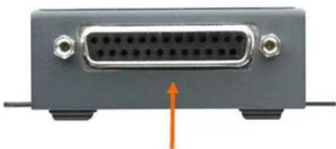
natural_image
Front view of a gray electronic device rear panel with a 24-pin connector and an orange arrow pointing to it (no text or symbols visible)DB25 Serial Port
Serial Connector Pinouts
The unit's female DB25 connector provides an RS-232C, RS-485, or RS-422 DCE serial port. The default serial port settings are 9600 baud, 8 bits, no parity, and 1 stop bit.
Figure 12-2. DB25 Female DCE Interface RS232
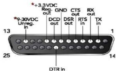
DB25 Female DCE Interface RS232
*Optional power connection
Figure 12-3. DB25 Female Interface RS422 (4 wire mode)
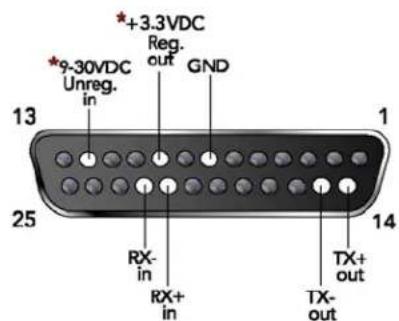
DB25 Female DCE Interface RS485/422
*Optional power connection
Figure 12-4. DB25 Female Interface RS485 (2 wire mode)
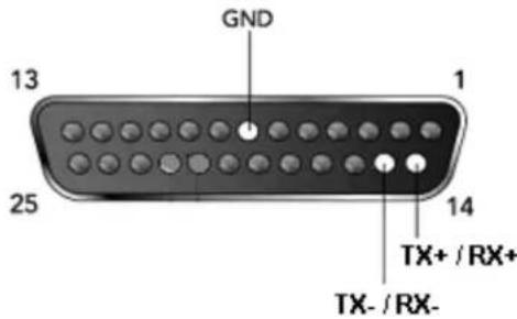
Modem Cable
When attaching the DB25 of the SDS1101 to the DB9 com port on a PC, use a standard straight-through serial cable. The figure below shows the pinouts for a DB25 to DB9 straight-through cable, often referred to as a "Modem Cable".
To configure the SDS using the DB9 serial port, you need only pin out the TXD, RXD, and GND signals.
Figure 12-5. Modem Cable
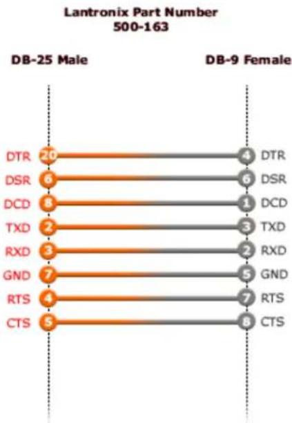
bar
Lantronix Part Number 500-163 | Sample | Count | | :--- | :--- | | DTR | 20 | | DSR | 6 | | DCD | 8 | | TXD | 2 | | RXD | 3 | | GND | 7 | | RTS | 4 | | CTS | 5 | | DTR | 4 | | DSR | 6 | | DCD | 1 | | TXD | 3 | | RXD | 2 | | GND | 5 | | RTS | 7 | | CTS | 8 |Network Port
The unit's back panel contains a power plug and an RJ45 (10/100) Ethernet port.
Figure 12-6. Network Interface
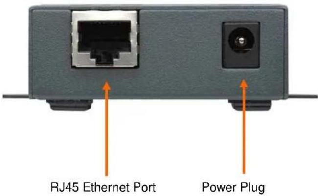
Ethernet Connector Pinouts
The SDS1101 supports 10/100 Mbps half or full duplex Ethernet through an RJ45 connector.
Figure 12-7. RJ45 Ethernet Connector
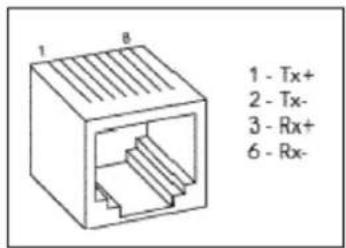
Power Plug
Power input on the power plug is 9 -30 VDC (center +) or 10-24 VAC (1.5W maximum power required).
13: SDS2101 Connections and Pinouts
The SDS2101 has two male DB9 DTE serial ports that support RS-232C/RS-422 (4-wire)/RS-485 (2-wire) serial standards up to 230 Kbps (and up to 921 Kbps if high performance is selected).
Figure 13-1. Serial Interface
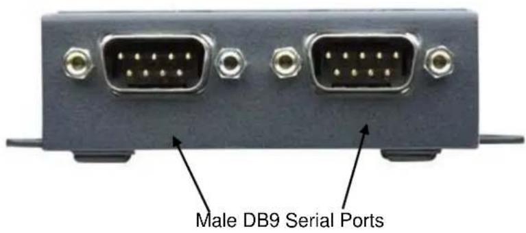
Serial Connector Pinouts
The two Male DB9 DTE connectors provide an RS-232C/RS-422 (4-wire)/RS-485 (2-wire) interface. The default serial port settings are 9600 baud, 8 bits, no parity, 1 stop bit, no flow control.
Figure 13-2. DB9 Male RS232 Serial DTE Connector
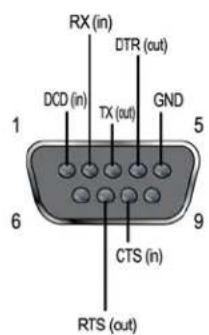
DB9M in RS232 Mode
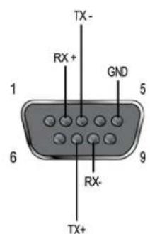
DB9M in RS422 (4-Wire) Mode
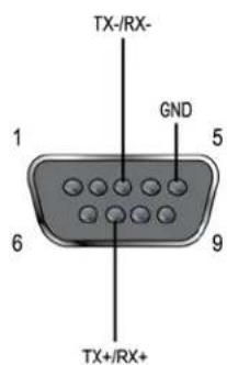
DB9M in RS485 (2-Wire) Mode
Network Port
The unit's back panel contains a 9-30VDC power plug and an RJ45 (10/100) Ethernet port.
Figure 13-3. Network Interface
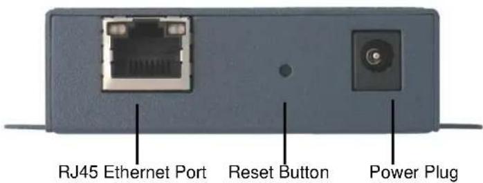
Reset Button
You can reset the unit to factory defaults, including clearing the network settings (IP address, gateway, and netmask are set to 00s).
To reset the unit to factory defaults:
- Place the end of a paper clip or similar object into the reset opening and press for a minimum of 3 seconds.
- Release the button and remove the paper clip. The firmware restores factory default settings to the configuration and invokes a reset (internally).
Ethernet Connector Pinouts
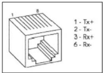
Power Plug
Power input on the power plug is 9-30 VDC (center +) (1.8W maximum power).
14: SDS1101 Technical Specifications
Table 14-1. SDS1101 Technical Specifications
| Category | Description | |
| CPU | Lantronix DSTNI-EX 48 MHz clock | |
| Internal CPU Memory | 256 KB zero wait state SRAM | |
| Flash | 2 MB Flash | |
| EEPROM | 2 KB EEPROM | |
| Serial Interface | 1 DB25F DCE serial portSoftware-selectable baud rate from 300 to 230 KBaudSoftware-selectable RS232, RS422 or RS485 (2 and 4 wire support) | |
| Serial Line Formats | Characters: 7 or 8 data bitsStop bits: 1 or 2Parity: odd, even, none | |
| Modem Control DTR, D$R | ||
| Flow Control | Hardware: CTS/RTSSoftware: XON/XOFF | |
| Power Input | 9-30 VDC or 9-24 VAC on barrel connector (1.5 Watts maximum consumption)9-30 VDC on DB25F serial interface | |
| Network Interface | 1 RJ45 10Base-T/100Base-TX Ethernet portSoftware selectable Ethernet speed 10/100/AutoSoftware selectable Half/Full/Auto duplex | |
| Dimensions | Height: 2.3 cm (0.9 in)Width: 6.4 cm (2.5 in)Depth: 9.0 cm (3.5 in) | |
| Weight | 0.20 kg (0.45 lb) | |
| Temperature | Operating range: 0° to 60° C (32° to 140° F)Note: Operating range for SDS1101-IAP only: -40° to 70° C (-40° to 158° F)Storage -40° to 85° C (-40 to 185° F) | |
| Relative Humidity | Operating 10% to 90% non-condensing, 40% to 60% recommendedStorage 10% to 90% non-condensing | |
| Case | Metal enclosure with integrated wall mountsOptional 35 mm Din Rail mount available | |
| Protocols Supported | ARP, UDP/IP, TCP/IP, Telnet, ICMP, SNMP, DHCP, BOOTP, TFTP, and HTTP | |
| Installable Industrial Protocols | ModBus TCP, ModBus ASCII/RTU, DF1 Multi-Master (IAP version only) | |
| Management | Internal web serverSNMP (read only)Serial login | |
| Telnet loginDeviceInstaller software | ||
| System Software | DeviceInstaller, Windows® 95/98/ME/NT/2000/XP-based configuration softwareCom Port Redirector, Windows® 98/NT/2000/XP-based virtual com port software | |
| LEDs | Power10/100 Mb Link10/100 ActivityDiagnosticStatus | |
| Emissions | FCC Part 15 Subpart B Class A ICES-003 Issue 4 February 2004 Class A AS/NZS CISPR 22: 2004 Class A EN55022: 1998 + A1: 2000 + A2: 2003 Class A 1000MHzVCCI V-3/2005.04 Class A EN61000-3-2: 2000 Class A EN61000-3-3: 1995 + A1: 2001 | Radiated Emissions 30MHz – 1000MHzRadiated Emissions 30MHz – 1000MHzRadiated Emissions 30MHz – 1000MHzRadiated Emissions 30MHz – 1000MHzHarmonic Current EmissionsFluctuations and Flicker |
| Immunity | EN55024: 1998 +A1: 2001 +A2: 2003IEC_61000-4-2: 1995 (Direct/Indirect)IEC_61000-4-3: 1995 IEC_61000-4-4: 1995 IEC_61000-4-5: 1995 ModeIEC_61000-4-6: 1996 IEC_61000-4-8: 1993 IEC_61000-4-11: 1994 Periods), (>95%, 250 periods) | ESD 8KV Air Discharge (Direct), 4KV Contact Discharge Radiated Immunity 3.0V/m, 1KHz AM Sine Wave at 80%EFT/Burst 1.0KV Power Lines, 0.5KV I/O LinesSurge Immunity 1.0KV Common Mode, 1.0 KV Differential Conducted Immunity 3.0 Vrms, 80% AM Modulated (1KHz)Magnetic Field Immunity 50Hz 1.0 Arms/mVoltage Dips and Interrupts (>95%, 0.5 periods), (30%, 25 |
| Isolation | Designed with protections against transients and ESD for use under harsh environmentsSerial Port: 15 KV ESD protection on RS232 and RS422/485 transceiversPower Input: Up to non-repeated 600 W 10/100 usec pulse protection against transient over voltagesEthernet Port: 1500 VAC isolation shielded with shield connected to chassis ground for signal integrity and ESD protection | |
| Agency Approvals | UL, CSA, FCC, CE, TUV, CTick, VCCI | |
15: SDS2101 Technical Specifications
Table 15-1. SDS2101 Technical Specifications
| Category | Description |
| CPU | Lantronix DSTNI-EX 48 MHz clock |
| Internal CPU Memory | 256 KB zero wait state SRAM |
| Flash | 2 MB Flash |
| EEPROM | 2 KB EEPROM |
| Serial Interface | 2 DB9M DTE serial portsSoftware-selectable baud rate from 300 to 921K baud (when High Performance is selected)Software-selectable RS232, RS422 or RS485 (2 and 4 wire support) |
| Serial Line Formats | Characters: 7 or 8 data bitsStop bits: 1 or 2Parity: odd, even, none |
| Modem Control | DTR, Modem Control In |
| Flow Control | Hardware: CTS/RTSSoftware: XON/XOFF |
| Power Input | 9-30 VDC on barrel connector (1.8W maximum consumption) |
| Network Interface | 1 RJ45 10Base-T/100Base-TX Ethernet portSoftware selectable Ethernet speed 10/100/AutoSoftware selectable Half/Full/Auto duplex |
| Dimensions | Height: 2.3 cm (0.9 in)Width: 7.3 cm (2.9 in)Length: 9.5 cm (3.75 in) |
| Weight | 0.26 kg (0.6 lb) |
| Temperature | Operating range: 0° to 60°C (32° to 140°F)Note: Operating range for SDS2101-IAP only: -40° to 70°C (-40° to 158°F)Storage -40° to 85°C (-40 to 185°F) |
| Relative Humidity | Operating 10% to 90% non-condensing, 40% to 60% recommendedStorage 10% to 90% non-condensing |
| Case | Metal enclosure with integrated wall mountsOptional 35 mm Din Rail mount available |
| Protocols Supported | ARP, UDP/IP, TCP/IP, Telnet, ICMP, SNMP, DHCP, BOOTP, TFTP, and HTTP |
| Installable Industrial Protocols | ModBus TCP, ModBus ASCII/RTU, DF1 Multi-Master (IAP version only) |
| Management Internal | web serverSNMP (read only)Serial loginTelnet loginDeviceInstaller software |
| System Software | Devicelnstaller, Windows® 95/98/ME/NT/2000/XP-based configuration softwareCom Port Redirector, Windows® 98/NT/2000/XP-based virtual com port software |
| LEDs | Power10/100 Mb Link on RJ4510/100 Activity on RJ45DiagnosticRX Serial 1 ActivityTX Serial 1 ActivityRX Serial 2 ActivityTX Serial 2 Activity |
| Emissions | FCC Part 15 Subpart B Class A Radiated Emissions 30MHz – 1000MHzICES-003 Issue 4 February 2004 Class A Radiated Emissions 30MHz – 1000MHzAS/NZS CISPR 22:2006 Class A Radiated Emissions 30MHz – 1000MHzEN55022: 1998 + A1: 2000 + A2: 2003 Class A Radiated Emissions 30MHz – 1000MHzVCCI V-3/2006.04 Class A Radiated Emissions 30MHz – 1000MHzEN61000-3-2: 2000 Class A Harmonic Current EmissionsEN61000-3-3: 1995 + A1: 2001 Fluctuations and Flicker |
| Immunity | EN55024: 1998 +A1: 2001 +A2: 2003IEC_61000-4-2: 1995 ESD 8KV Air Discharge (Direct), 4KV Contact Discharge (Direct/Indirect)IEC_61000-4-3: 1995 Radiated Immunity 3.0V/m, 1KHz AM Sine Wave at 80%IEC_61000-4-4: 1995 EFT/Burst 1.0KV Power Lines, 0.5KV I/O LinesIEC_61000-4-5: 1995 Surge Immunity 1.0KV Common Mode, 1.0 KV Differential ModeIEC_61000-4-6: 1996 Conducted Immunity 3.0 Vrms, 80% AM Modulated (1KHz)IEC_61000-4-8: 1993 Magnetic Field Immunity 50Hz 1.0 Arms/mIEC_61000-4-11: 1994 Voltage Dips and Interrupts (>95%, 0.5 periods), (30%, 25 periods), (>95%, 250 periods) |
| Isolation | Designed with protections against transients and ESD for use under harsh environmentsSerial Port: 15 KV ESD protection on RS232 and RS422/485 transceiversPower Input: Up to non-repeated 600 W 10/100 usec pulse protection againsttransient over voltagesEthernet Port: 1500 VAC isolation shielded with shield connected to chassis ground for signal integrity and ESD protection |
| Agency Approvals | UL, CSA, FCC, CE, TUV, CTick, VCCI |
A: Alternative Ways to Assign an IP Address
Earlier chapters describe how to assign a static IP address using Devicelnstaller, Web Manager, and Setup Mode (through a Telnet or serial connection). This section covers other methods for assigning an IP address over the network.
DHCP
The unit ships with a default IP address of 0.0.0.0, which automatically enables DHCP. If a DHCP server exists on the network, it provides the unit with an IP address, gateway address, and subnet mask when the unit boots up.
You can use the DeviceInstaller software to search the network for the DHCP-assigned IP address and add it to the list of devices retrieved.
Note: This DHCP address does not appear in the unit's Setup Mode or in Web Manager. You can determine your unit's DHCP-assigned IP address in Monitor Mode. When you enter Monitor Mode from the serial port with network connection enabled and issue the NC (Network Communication) command, you see the unit's IP configuration.
AutoIP
The unit ships with a default IP address of 0.0.0.0, which automatically enables Auto IP within the unit. AutoIP is an alternative to DHCP that allows hosts to obtain an IP address automatically in smaller networks that may not have a DHCP server. A range of IP addresses (from 169.254.0.1 to 169.254.255.1) has been explicitly reserved for AutoIP-enabled devices. Do not use this range of Auto IP addresses over the Internet.
If your unit cannot find a DHCP server, and you have not manually assigned an IP address to it, the unit automatically selects an address from the AutoIP reserved range. Then, your unit sends out a (ARP) request to other nodes on the same network to see whether the selected address is being used.
If the selected address is not in use, then the unit uses it for local subnet communication.
If another device is using the selected IP address, the unit selects another address from the AutoIP range and reboots. After reboot, the unit sends out another ARP request to see if the selected address is in use, and so on.
AutoIP does not replace DHCP. The unit continues to look for a DHCP server on the network. If it finds a DHCP server, the unit switches to the DHCP server-provided address and reboots.
Note: If a DHCP server is found, but it denies the request for an IP address, the unit does not attach to the network, but waits and retries.
AutoIP can be disabled by setting the unit's IP address to 0.0.1.0. This setting enables DHCP but disables AutoIP.
BOOTP
Similar to DHCP, but for smaller networks. Automatically assigns the IP address for a specific duration of time.
ARP and Telnet
If the unit has no IP address, you can use Address Resolution Protocol (ARP) method from UNIX and Windows-based systems to assign a temporary IP address.
To assign a temporary IP address:
- On a UNIX or Windows-based host, create an entry in the host's ARP table using the intended IP address and the hardware address of the unit (on the product label on the bottom of the unit).
$$ \text { arp } - s 1 9 1. 1 2. 3. 7 7 0 0: 2 0: 4 a: x x: x x: x x (\text { Unix }) $$
$$ \text { arp -s 191.12.3.77 00 - 20 - 4a - xx - xx - xx } \quad (\text { Windows }) $$
Note: For the ARP command to work on Windows 95, the ARP table on the PC must have at least one IP address defined other than its own.
- If you are using Windows 95, type ARP -A at the DOS command prompt to verify that there is at least one entry in the ARP table. If the local machine is the only entry, ping another IP address on your network to build a new entry in the ARP table; the IP address must be a host other than the machine on which you are working. Once there is at least one additional entry in the ARP table, use the following command to ARP an IP address to the unit:
$$ \text { arp } - s 1 9 1. 1 2. 3. 7 7 0 0 - 2 0 - 4 a - x x - x x - x x $$
- Open a Telnet connection to port 1. The connection fails quickly, but the unit temporarily changes its IP address to the one designated in this step.
telnet 191.12.3.77 1
- Open a Telnet connection to port 9999, and press Enter within five seconds to go into Setup Mode. If you wait longer than five seconds, the unit reboots.
telnet 191.12.3.77 9999
Note: The IP address you just set is temporary and reverts to the default value when the unit's power is reset, unless you configure the unit with a static IP address and store the changes permanently.
B: Binary to Hexadecimal Conversions
Many of the unit's configuration procedures require assembling a series of options (represented as bits) into a complete command (represented as a byte). Convert the resulting binary value to a hexadecimal representation.
Converting Binary to Hexadecimal
Following are two simple ways to convert binary numbers to hexadecimals.
Conversion Table
Hexadecimal digits have values ranging from 0 to F, which are represented as 0-9, A (for 10), B (for 11), etc. To convert a binary value (for example, 0100 1100) to a hexadecimal representation, the upper and lower four bits are treated separately, resulting in a two-digit hexadecimal number (in this case, 4C). Use the following table to convert values from binary to hexadecimal.
| Decimal | Binary | Hex |
| 0 | 0000 | 0 |
| 1 0001 1 | ||
| 2 0010 2 | ||
| 3 | 0011 | 3 |
| 4 | 0100 | 4 |
| 5 | 0101 | 5 |
| 6 | 0110 | 6 |
| 7 | 0111 | 7 |
| 8 1000 8 | ||
| 9 1001 9 | ||
| 10 | 1010 | A |
| 11 | 1011 | B |
| 12 | 1100 | C |
| 13 | 1101 | D |
| 14 1110 E | ||
| 15 1111 F |
Scientific Calculator
Another simple way to convert binary to hexadecimals is to use a scientific calculator, such as the one available on Windows' operating systems. For example:
- On the Windows' Start menu, click Programs→Accessories→Calculator.
- On the View menu, select Scientific. The scientific calculator displays.
- Select Bin (Binary), and type the number to convert.
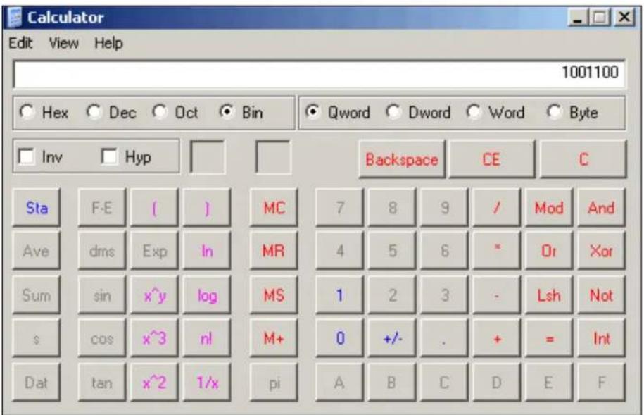
- Click Hex. The hexadecimal value displays.
C: Warranty
For details on the Lantronix warranty replacement policy, please go to our Web site at www.lantronix.com/support/warranty.
D: Compliance and Disclaimer
Manufacturer's Name & Address
Lantronix
167 Technology Drive
Irvine, CA 92618 USA
Declares that the following product:
Product Name Model: SDS1101 and SDS2101 Device Servers
Conforms to the following standards or other normative documents:
Safety
UL 60950-1
CSA 22.2. No 60950-1-03
EN 60950-1
TUV
VCCI
C-TICK
Electromagnetic Emissions
FCC Part 15 Subpart B Class A
ICES-003 Issue 4 February 2004 Class A
AS/NZS CISPR 22: 2004 Class A
EN55022: 1998 + A1: 2000 + A2: 2003 CLASS A
EN61000-3-2: 2000 Class A
EN61000-3-3: 1995 +A1: 2001
VCCI
V-3/2006.04 Class A (SDS2101 only)
Electromagnetic Immunity
EN55024: 1998 +A1: 2001 +A2: 2003
IEC 61000-4-2: 1995
IEC 61000-4-3: 1995
IEC 61000-4-4: 1995
IEC 61000-4-5: 1995
IEC 61000-4-6: 1996
IEC 61000-4-8: 1993
IEC 61000-4-11: 1994
RoHS Notice
All Lantronix products in the following families are China RoHS-compliant and free of the following hazardous substances and elements:
- Lead (Pb)
- Cadmium (Cd)
- Mercury (Hg)
• Polybrominated biphenyls (PBB)
• Hexavalent Chromium (Cr (VI))
• Polybrominated diphenyl ethers (PBDE)
| Product Family Name | Toxic or hazardous Substances and Elements | |||||
| Lead (Pb) | Mercury (Hg) | Cadmium (Cd) | Hexavalent Chromium (Cr (VI)) | Polybrominated biphenyls (PBB) | Polybrominated diphenyl ethers (PBDE) | |
| UDS1100 and 2100 | 0 | 0 | 0 | 0 | 0 | 0 |
| EDS | 0 | 0 | 0 | 0 | 0 | 0 |
| MSS100 | 0 | 0 | 0 | 0 | 0 | 0 |
| IntelliBox | 0 | 0 | 0 | 0 | 0 | 0 |
| XPress DR & XPress-DR+ | 0 | 0 | 0 | 0 | 0 | 0 |
| SecureBox 1101 & 2101 | 0 | 0 | 0 | 0 | 0 | 0 |
| WiBox | 0 | 0 | 0 | 0 | 0 | 0 |
| UBox | 0 | 0 | 0 | 0 | 0 | 0 |
| MatchPort | 0 | 0 | 0 | 0 | 0 | 0 |
| SLC | 0 | 0 | 0 | 0 | 0 | 0 |
| XPort | 0 | 0 | 0 | 0 | 0 | 0 |
| WiPort | 0 | 0 | 0 | 0 | 0 | 0 |
| SLB | 0 | 0 | 0 | 0 | 0 | 0 |
| SLP | 0 | 0 | 0 | 0 | 0 | 0 |
| SCS | 0 | 0 | 0 | 0 | 0 | 0 |
| SLS | 0 | 0 | 0 | 0 | 0 | 0 |
| DSC | 0 | 0 | 0 | 0 | 0 | 0 |
O: toxic or hazardous substance contained in all of the homogeneous materials for this part is below the limit requirement in SJ/T11363-2006.
X: toxic or hazardous substance contained in at least one of the homogeneous materials used for this part is above the limit requirement in SJ/T11363-2006.
Disclaimer and Supplementary Information
This product has been designed to comply with the limits for a Class A digital device pursuant to Part 15 of FCC Rules. These limits are designed to provide reasonable protection against such interference when operating in a commercial environment. This equipment generates, uses, and can radiate radio frequency energy, and if not installed and used in accordance with this guide, may cause harmful interference to radio communications. Operation of this equipment of this equipment in a residential area is likely to cause harmful interference in which case the user will be required to correct the interference at user own expense.
This Class A digital apparatus complies with Canadian ICES-003
The product complies with the requirements of the Low Voltage Directive 72/23/EEC and the EMC Directive 89/336/EEC.
Encryption: This product includes AES encryption certified by the National Institute of Standard and Technology to FIPS-197 standard certification #120.
Export Control Classification Number 5A002, License exception ENC.
Changes or modifications to this device not explicitly approved by Lantronix will void the user's authority to operate this device. The information in this guide may change without notice. The manufacturer assumes no responsibility for any errors that may appear in this guide.
Manufacturer's Contact
167 Technology Drive
Irvine, CA 92618 USA
Toll Free: 800-526-8766
Phone: 949-453-3990
Fax: 949-450-7249
Index
Applications, 11
ARP and Telnet, 88
AutolP, 17, 87
Binary to hexadecimal conversions, 89
BOOTP, 17, 88
Channel settings, 29, 44
Command line interface, 38
Configuration methods, 13
Connect Mode, 46
Connection settings
TCP, 32
UDP, 35
Connectors, 76, 80
Contacts, 2
CPU Performance, 59
Default settings
applying in Setup Mode, 64
applying in Web-Manager, 37
DeviceInstaller
accessing the unit, 23
assigning the IP address, 18
installing from product CD, 18
DHCP, 17, 87
DHCP name. See
Error messages, 72
Ethernet address, 14
Expert settings, 59
Firmware
recovering, 67
upgrading, 66
Gateway, 41
Getting started, 15
Hardware address, 14, 17
Host list settings
Setup Mode, 49
Web-Manager, 28
Installation, 16
Internal web server, 13
IP address
assigning, 18, 25, 41
automatic assignment, 25
factory default, 17
gateway, 41
other ways to assign, 87
requirement, 17
searching for on the network, 19
show after ring, 54
Label, 14
LEDs, 71, 72
MAC address, 14
Modem emulation, 13
Modem Mode, 51
Monitor Mode, 69
Netmask, 42
Network settings, 24
Null modem cable, 77
Package contents, 15
Password for Telnet configuration, 42
Pinouts, 76, 80
Ethernet connector, 79
serial connector, 76
Power plug, 78
Problems, 72
Protocols, 13
Redirection software, 12
Required information, 17
RJ45 Ethernet port, 78
RoHS notice, 93
RS-232 and RS-485/422 standards, 76
Security settings, 60
Serial port
accessing Setup Mode, 21
login, 21
Serial tunneling, 11
Server settings
Setup Mode, 41
Web-Manager, 26
Setup Mode, 38
accessing by serial port connection, 39
accessing by Telnet. See
SNMP, 61
TCP settings, 32
Technical specifications
Technical Support, 74
TFTP, 66
Troubleshooting, 9, 71
UDP settings, 35
Warranty, 91
Web-Manager, 23
- Contacts
- Lantronix
- Technical Support
- Sales Offices
- Disclaimer
- Revisions
- Contents
- 1: Using This Guide 9
- 2: Introduction 11
- 3: Getting Started 15
- 4: Configuration Using Web-Manager
- 5: Configuration via Telnet or Serial Port (Setup Mode)
- 6: Setup Mode: Server Configuration 41
- 7: Setup Mode: Channel Configuration 44
- 8: Setup Mode: Advanced Settings 59
- 9: Firmware Upgrades 66
- 10: Monitor Mode 69
- 11: Troubleshooting and Contact Information 71
- 12: SDS1101 Connections and Pinouts 76
- 13: SDS2101 Connections and Pinouts 80
- 14: SDS1101 Technical Specifications 82
- 15: SDS2101 Technical Specifications 84
- A: Alternative Ways to Assign an IP Address 87
- B: Binary to Hexadecimal Conversions 89
- C: Warranty 91
- D: Compliance and Disclaimer 92
- Index 95
- Figures
- Tables
- 1: Using This Guide
- Purpose and Audience
- Chapter Summary
- Additional Documentation
- 2: Introduction
- Applications
- Application Examples
- Protocol Support
- Additional Features
- Configuration Methods
- Product Information Label
- 3: Getting Started
- Package Contents
- Installing the SDS
- To install the unit:
- Required Information
- Hardware Address
- IP Address
- Assigning the IP Address: DeviceInstaller
- Installing Devicelnstaller
- Assigning an IP Address
- To assign an IP address manually:
- Adding the Unit to the Manage List
- Accessing the SDS1101/2101 Using Devicelnstaller
- Viewing the Current Configuration
- To view the unit's current settings:
- Next Step
- To configure the unit using a Web browser:
- To configure the unit using a Telnet session:
- Assigning the IP Address: Serial Port Login
- Accessing SDS1101/2101 Using DeviceInstaller
- Network Configuration
- Automatic IP Address Configuration
- To assign an IP address automatically:
- Static IP Address Configuration
- Ethernet Configuration
- To specify how data will be transmitted:
- Server Configuration
- To configure the SDS's device server settings:
- Host List Configuration
- To configure the host list:
- Channel 1 & Channel 2 (SDS2101 only) Configuration
- Serial Settings
- Connection Settings - TCP
- To configure a channel's TCP settings:
- Connection Settings - UDP
- To configure a channel's UDP settings:
- Apply Settings
- Apply Factory Defaults
- Accessing Setup Mode
- Telnet Connection
- To establish a Telnet connection:
- Serial Port Connection
- Exiting Setup Mode
- 6: Setup Mode: Server Configuration
- Server Configuration (Option 0)
- Set Gateway IP Address
- Netmask: Number of Bits for Host Part
- Change Telnet Configuration Password
- DHCP Name
- 7: Setup Mode: Channel Configuration
- Notes:
- Channel 1 (Option 1) & Channel 2 (Option 2 on SDS2101 only)
- Baudrate
- I/F (Interface) Mode
- Flow
- Port Number
- Warning: We recommend that you not use the reserved port numbers for this setting as incorrect operation may result.
- Connect Mode
- To enable the hostlist:
- d) Datagram Type
- e) Modem Mode
- Send the Escape Sequence (+++) in Modem Mode
- Show IP addr after 'RING'
- Auto Increment Source Port
- Remote IP Address
- Remote Port
- DisConnMode
- Flush Mode (Buffer Flushing)
- Pack Control
- Packing Interval
- Trailing Characters
- Send Characters
- DisConnTime (Inactivity Timeout)
- Telnet Terminal Type
- Channel (Port) Password
- 8: Setup Mode: Advanced Settings
- Expert Settings (Option 5)
- ARP Cache timeout in seconds
- CPU Performance (SDS2101 only)
- Disable Monitor Mode at bootup
- HTTP Port Number
- MTU Size
- Enable alternate MAC
- Ethernet connection type
- Security Settings (Option 6)
- Disable SNMP
- SNMP Community Name
- Disable Telnet Setup
- Disable TFTP Firmware Update
- Disable Port 77FE (Hex)
- Disable Web Server
- Disable Web Setup
- Disable ECHO Ports
- Enable Enhanced Password
- Enable Encryption
- To configure AES encryption on the SDS:
- Default Settings (Option 7)
- 9: Firmware Upgrades
- Obtaining Firmware
- Reloading Firmware
- Using TFTP: Graphical User Interface
- To download new firmware from a computer:
- Using TFTP: Command Line Interface
- SDS1101
- SDS2101
- Recovering the Firmware Using the Serial Port and DeviceInstaller
- To recover firmware:
- 10: Monitor Mode
- Entering Monitor Mode Using the Serial Port
- To enter Monitor Mode locally:
- Entering Monitor Mode Using the Network Port
- To enter Monitor Mode using a Telnet connection:
- Monitor Mode Commands
- 11: Troubleshooting and Contact Information
- SDS1101 LEDs
- SDS2101 LEDs
- Problems and Error Messages
- Technical Support Europe, Middle East, and Africa
- 12: SDS1101 Connections and Pinouts
- Serial Port
- Serial Connector Pinouts
- Modem Cable
- Network Port
- Ethernet Connector Pinouts
- Power Plug
- 13: SDS2101 Connections and Pinouts
- Reset Button
- To reset the unit to factory defaults:
- 14: SDS1101 Technical Specifications
- 15: SDS2101 Technical Specifications
- A: Alternative Ways to Assign an IP Address
- DHCP
- AutoIP
- BOOTP
- ARP and Telnet
- To assign a temporary IP address:
- B: Binary to Hexadecimal Conversions
- Converting Binary to Hexadecimal
- Conversion Table
- Scientific Calculator
- C: Warranty
- D: Compliance and Disclaimer
- Manufacturer's Name & Address
- Safety
- Electromagnetic Emissions
- Electromagnetic Immunity
- RoHS Notice
- Disclaimer and Supplementary Information
- Manufacturer's Contact
- Index
Brand : Lantronix
Model : SecureBox SDS1101
Category : Server