
Apprentice 15e PNP - Toy E-flite - Free user manual and instructions
Find the device manual for free Apprentice 15e PNP E-flite in PDF.


| Product Type | RC Airplane (Trainer) |
| Brand | E-flite |
| Model | Apprentice 15e PNP |
| Category | Toy / Hobby |
| Wingspan | 1500 mm (approx) |
| Length | 1100 mm (approx) |
| Weight | 1200 g (approx) |
| Motor | 15-size brushless outrunner (e.g., 480L) |
| ESC | 30A brushless |
| Servos | 4 pre-installed (aileron, elevator, rudder) |
| Battery Requirement | 3S 11.1V LiPo 3200mAh (recommended) |
| Radio System | 4+ channel transmitter and receiver (not included) |
| Flight Modes | Beginner (self-leveling), Intermediate, Expert; panic recovery |
| Materials | EPO foam |
| Assembly Level | Plug-N-Play (requires receiver and battery) |
| Cleaning Instructions | Damp cloth; avoid solvents |
| Maintenance | Check screws, prop balance, and control surfaces |
| Safety Warnings | Keep away from people and water; fly in open areas |
| Spare Parts Common | Propeller, landing gear, motor mount |
| Repairability | Easy with foam-safe CA glue |
Frequently Asked Questions - Apprentice 15e PNP E-flite
User questions about Apprentice 15e PNP E-flite
0 question about this device. Answer the ones you know or ask your own.
Ask a new question about this device
Download the instructions for your Toy in PDF format for free! Find your manual Apprentice 15e PNP - E-flite and take your electronic device back in hand. On this page are published all the documents necessary for the use of your device. Apprentice 15e PNP by E-flite.
USER MANUAL Apprentice 15e PNP E-flite
natural_image
Black-and-white photo of a white and black propeller airplane in flight against a cloudy sky (no visible text or symbols)Specifications
Wingspan: 58 in (1475mm)
Length: 37 in (940mm)
Wing Area: 525 sq in (33.7 sq dm)
Weight w/o Battery: 32-35 oz (910-1000 g)
Weight w/Battery: 40-45 oz (1135-1275 g)

Table of Contents
Introduction 2
Important Warranty Information 2
Using the Manual 2
Product Registration.... 2
Contents of Kit/Parts Layout 2
Required Radio Equipment 3
Battery 3
Charger 3
Required Tools and Adhesives 3
Optional Accessories 3
Note on Lithium Polymer Batteries 3
Charging the Flight Battery 3
AR500 Receiver Installation 3
AR6200 Receiver Installation 4
Tail Installation 4
Landing Gear Installation 6
Wing Installation 6
Battery Installation 9
Removing the Propeller 10
Control Functions 12
Centering the Control Surfaces and
Checking Control Direction 12
Reversing Direction of Flight Controls 17
Center of Gravity 17
Range Test Your Radio....18
Setting the Control Throws 18
Installing the Propeller 20
Flying Your Apprentice 22
Safety Precautions 22
Safety Do's and Don'ts for Pilots 22
Warranty Information 22
CE Compliance Information for the
European Union 24
2009 Official Academy of
Model Aeronautics Safety Code 24
Declaration of Conformity 26
Introduction
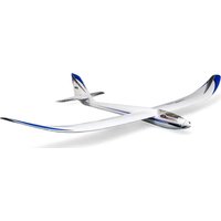
E-flite's Apprentice™ 15e Plug-N-Play™ is a 15-size high-wing club trainer that comes with nearly everything you need to go from purchase to the flying field. No building required—just charge and install your battery, mount the wing and tail surfaces and fly by utilizing your own transmitter and receiver. The Apprentice is made from durable, lightweight Z-Foam™, making it tough enough to handle the punishment of early training mishaps without getting bent out of shape. When using the recommended E-flite® 11.1V 3200mAh battery, you can expect extended flight times of 15 minutes or more.
The Apprentice is the perfect training aircraft thanks to its gentle flight characteristics. Once the pilot has learned the basics of flight, the Apprentice is capable of performing loops, rolls, inverted flying and other aerobatic maneuvers. It's also equipped with tricycle landing gear for better ground handling.
Learn to fly the basics and beyond with E-flite's Apprentice PNP.
Important Warranty Information
Please read our Warranty and Liability Limitations section on Page 22 before building this product. If you as the Purchaser or user are not prepared to accept the liability associated with the use of this Product, you are advised to return this Product immediately in new and unused condition to the place of purchase.
Using the Manual
This manual is divided into sections to help make assembly easier to understand, and to provide breaks between each major section. In addition, check boxes have been placed next to each step to keep track of its completion. Steps with a single circle (O) are performed once, while steps with two circles (O O) indicate that the step will require repeating, such as for a right or left wing panel, two servos, etc.
Remember to take your time and follow the directions.
Product Registration
Register your product online at:
www.e-fliterc.com/register/
Contents of Kit/Parts Layout
EFL2726 Wing Set
EFL2727 Fuselage
EFL2728 Tail Set
EFL2729 Cowl
EFL2730 Pushrod Set
EFL2731 Nose Gear
EFL2732 Main Landing Gear
EFL2733 Spinner
EFL2734 Motor Mount
EFL2735 5mm Prop Adapter
EFLA1030 30-Amp Pro Switch-mode
BEC Brushless ESC
EFLM7215 BL15 Outrunner, 840Kv motor
EFLP11080E 11 x 8 Electric Propeller
EFLR7140 13-gram Sub-Micro Servo (used on elevator and ailerons)
EFLR7150 37-gram Standard Servo
(used on rudder)

natural_image
Exploded view of a propeller aircraft model with cutaway views and labeled parts (no readable text or symbols)Required Radio Equipment
The Apprentice PNP requires a 4-channel transmitter and full-range receiver. Users of Spektrum's DX5e 2.4GHz radio system will need an AR500 5-channel receiver (SPMAR500).
Complete Radio System
SPM5500 DX5e 5-Channel Full Range w/o Servos
Or Purchase Separately
SPMAR500 AR500 5-Channel Receiver
Or
SPMAR6200 AR6200 6-Channel Ultralite Receiver
Battery
EFLB1040 11.1V 3200mAh 15C 3-Cell Li-Po, 13AWG w/EC3
Or
EFLB32003S 11.1V 3200mAh 20C 3-Cell Li-Po, 13AWG w/EC3
Or
THP33003SXV 11.1V 3300mAh 25C 3-Cell Extreme V2 Li-Po
Charger
EFLC505 1-5 Cell Li-Po Charger w/Balancer
Or
THP610 610C 1-6 Cell Li-Po 0.25-10A DC Charger w/Balancer
Optional
THP1205P AC-12V DC, 5A Power Supply
Required Tools and Adhesives
Tools & Equipment
EFLA250 Parkflyer Tool Assortment, 5-piece
Or Purchase Separately
Adjustable wrench Ruler
30-minute epoxy Mixing cup
Mixing sticks Epoxy brush
Paper towel Rubbing alcohol
Low-take tape
Phillips screwdriver: #1
Optional Accessories
EFLA110 Power Meter EFLP11080E 11x8 Electric Prop EFLA208 Foam CA 1oz/ Activator 2oz Pack SPM6805 Trainer Cord
Note on Lithium Polymer Batteries

Lithium Polymer batteries are significantly more volatile than alkaline or Ni-Cd/Ni-MH batteries used in RC applications. All manufacturer's instructions and warnings must be followed closely. Mishandling of LiPo batteries can result in fire. Always follow the manufacturer's instructions when disposing of Lithium Polymer batteries.
Charging the Flight Battery
You will want to begin charging your battery so it is ready once the model is complete. Follow the instructions included with your charger and battery.
AR500 Receiver Installation
Required Parts
Fuselage assembly Hook and loop tape AR500 receiver Clear tape
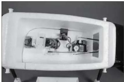
- Attach a piece of hook and loop tape to the back of the receiver. Insert the receiver into the pre-formed pocket in the fuselage as shown. Make sure to route and secure the antenna as shown in the photos below. Once you have the antenna routed correctly, secure it in place with a piece of clear tape.

- Plug the leads from the speed control, rudder servo and elevator servo into the appropriate ports of the receiver. Note the rudder servo is larger, and the elevator servo is smaller.
natural_image
Interior view of a white rectangular electronic device with internal components and wiring (no visible text or symbols)AR6200 Receiver Installation
Required Parts
Fuselage assembly Hook and loop tape AR6200 Receiver with remote receiver
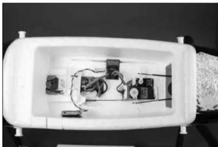
- Attach a piece of hook and loop material to the back of the main receiver. Insert the receiver into the pre-formed pocket in the fuselage as shown.

natural_image
Interior view of a white lab or testing chamber with electronic equipment and wiring (no visible text or symbols)- Attach a piece of hook and loop material to the back of the remote receiver. Mount the remote receiver on the left side of the fuselage (as viewed if sitting in the aircraft) as shown. The antennas should be vertical on the remote receiver as shown in the photo.

natural_image
Interior view of a white plastic container with visible electrical and mechanical components (no text or symbols)- Plug the leads from the speed control, rudder servo and elevator servo into the appropriate ports of the receiver. Note the rudder servo is larger, and the elevator servo is smaller.
natural_image
Interior view of a white electronic device with visible circuitry and components (no text or symbols)Tail Installation
Required Parts
Fuselage assembly Stabilizer/Elevator Fin/Rudder 2.5mm x 12mm sheet metal screw (2)
Required Tools
Phillips screwdriver: #1
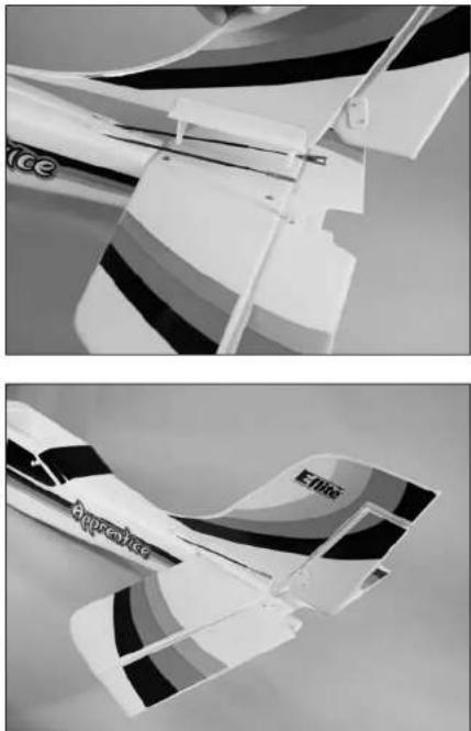
- Position the stabilizer on the fuselage. Align the holes in the stabilizer with the holes in the rear of the fuselage. The decals on the stabilizer will face toward the top of the fuselage.

natural_image
Close-up of a white aircraft fuselage with visible blade and wing structure (no text or symbols)- Slide the pins on the bottom of the fin through the holes of the stabilizer and into those in the fuselage. You will need to move the pushrods out of the way to each side to drop the fin all the way down. Make sure to seat the fin completely down on the horizontal stab. You might need to push the fin down with some slight pressure to fully seat it.
natural_image
Two grayscale images of a model airplane, one with visible tail fin and the other with patterned wings (no text or symbols)- Use a #1 Phillips screwdriver to install the two 2.5mm x 12mm sheet metal screws that secure the tail assembly to the fuselage. Tighten the screws until they stop. Do not overtighten as you may crack the plastic.

natural_image
Two-panel black-and-white photo showing a white model airplane being cut with a screwdriver, no visible text or symbols- Connect the elevator pushrod clevis to the elevator control horn in the hole that is farthest away from the elevator. Make sure to slide the silicone retainer onto the clevis to keep the clevis from popping off of the control horn.

natural_image
Close-up of a white industrial machine component with a curved blade and mounting bracket (no visible text or symbols)
- Connect the rudder pushrod clevis to the rudder control horn in the hole that is farthest away from the rudder. Make sure to slide the silicone retainer onto the clevis to keep the clevis from popping off of the control horn.

natural_image
Close-up of a white aircraft wing with black and white markings, no visible text or symbolsLanding Gear Installation
Required Parts
Fuselage assembly Nose gear w/wheel Main gear w/wheels
Required Tools
Phillips screwdriver: #1
- Locate the flat area on the nose gear. This area will be where the screw will be positioned in the following step.
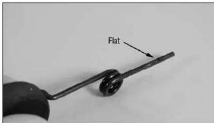
- You will need to back out the screw in the nose wheel steering arm before sliding in the nose gear wire. Slide the nose gear into the nose gear bracket. Use a #1 Phillips screwdriver to tighten the screw that secures the nose gear. Make sure the screw is tightened against the flat area as indicated in Step 1.

natural_image
Close-up of a hand using tweezers to adjust or install a white electronic device with a circular component (no visible text or symbols)6 E-flite Apprentice PNP Assembly Manual
E-tips
You may need to push the cowling out of the way slightly to access the screw. The cowl material is flexible enough to bend a little during this step without damage.
- Locate the main gear and press it into the slot in the fuselage that is behind the battery compartment on the bottom of the fuselage. You may need to flex the landing gear wire inwards towards itself to get it to fully seat inside the slot.

natural_image
Close-up of a white electronic device with ventilation slots and a hand holding a black clip (no visible text or symbols)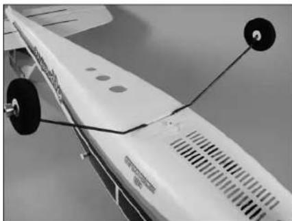
natural_image
Close-up of a white aircraft wing with visible propeller and two black circular components (no text or symbols)Wing Installation
Required Parts
Wing panel (right and left)
Wing cover, front
Wing cover, rear Rubber band (8)
Fuselage assembly Transmitter
Motor battery
Required Tools
30-minute epoxy Mixing cup
Mixing sticks Epoxy brush
Paper towel Rubbing alcohol
Low-tack tape
You will need to bind your radio system before you install the wing on the Apprentice in this section.
- Align the carbon wing tube with the socket in the opposite wing panel. Test fit the two panels by sliding them together. They should fit tightly together as shown.

natural_image
Close-up of a white cylindrical device with black leads, possibly a pen or tool, against a plain background (no visible text or symbols)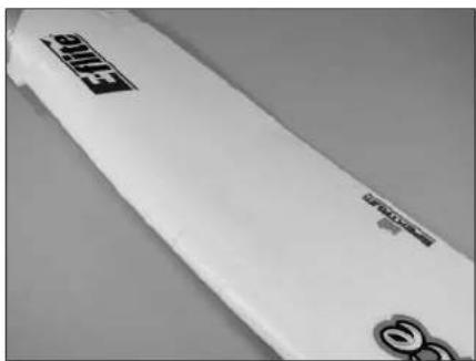
natural_image
Close-up of a white electronic device with black logo and 'PROVEA' branding (no readable text beyond branding)- Separate the wing panels. Mix 1/2-ounce (15mL) of 30-minute epoxy and apply it to the root of both the left and right wing panels.

natural_image
Hand holding a pen on paper with test tubes and a tool nearby (no visible text or symbols)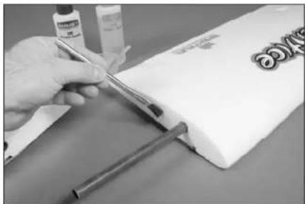
natural_image
Close-up of a hand using a tool to cut a white object with a metal rod (no visible text or symbols)- Slide the wing panels back together. Use low-tack tape to keep the panels held tightly together. Wrapping a piece of tape around the leading and trailing edge will keep the panels in alignment with each other. Use a paper towel soaked with rubbing alcohol to remove any excess epoxy before it cures. Allow the epoxy to fully cure before proceeding to the next step.

natural_image
Folded white paper with gray rectangular strips and a small inset of bottles and glasses (no visible text or symbols)
natural_image
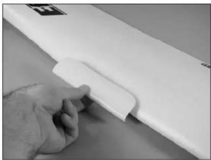
Close-up of a hand applying white adhesive to a rolled paper sheet with gray strips (no text or symbols visible)- Locate the front and rear wing covers. The front cover has a rounded edge, while the rear has a squared edge.


- Remove the backing from the adhesive tape on the front wing cover.

natural_image
Hand holding a white paper clip against a plain background (no text or symbols visible)- Make sure the two wing panels are pressed tightly together with no gap between them. Position the front wing cover in the notch at the front of the wing. Press the cover down to secure its position on the wing.
natural_image
Close-up of a hand holding a white plastic sheet with a small clip, no visible text or symbols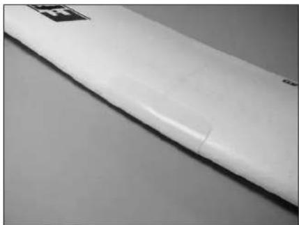
natural_image
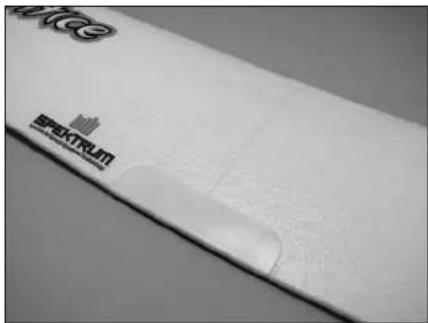
Close-up of a white cylindrical object with a black square mark on the top left, against a plain background (no text or symbols visible)- Repeat the previous step to install the rear wing cover.
natural_image
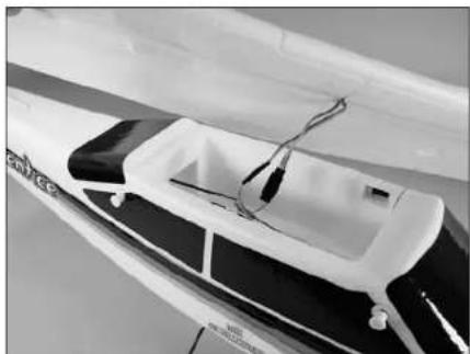
Close-up of a white electronic device with visible branding and a scroll wheel (no readable text or symbols)- Install the included Y-harness by plugging it into the "AILE" port of the receiver.

natural_image
Close-up of an electronic circuit board with wires and components, no visible text or symbols- Connect the aileron pushrod clevis to the aileron control horn in the hole that is farthest away from the aileron. Make sure to slide the silicone retainer onto the clevis to keep the clevis from popping off of the control horn. Connect both the right and left aileron linkages at this time.

natural_image
Close-up of a black cable with a small connector against a white grid background (no text or symbols visible)- Bind your radio system according to the manufacturers instructions at this time.
O 11. Connect the wires from the aileron servos to the Y-harness coming from the receiver.
natural_image
Close-up of a small aircraft fuselage with visible wiring and mounting feet (no text or symbols)- Install the first two rubber bands. They should cross as shown in the image below.

natural_image
Close-up of a white aircraft fuselage with visible branding and black accents (no readable text or symbols)- The next two rubber bands will go directly from the front to the rear of the fuselage, over the wing.

natural_image
Close-up of a white aircraft fuselage with black markings and visible tailoring (no text or symbols)- Install the remaining rubber bands using Steps 9 and 10 as a guide. You will install two across (as in step 9) and then two in line (as in step 10), and then two across (as in step 9) and then two in line (as in step 10), and so on until there are no more rubber bands.

natural_image
Close-up of a white model airplane with visible branding and no readable text or symbolsBattery Installation
Required Parts
Assembled airframe
3200 3S 11.1 V LiPo battery (charged)
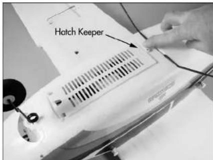
- Lay the model upside-down and turn the battery hatch keeper 90 degrees to release the hatch.
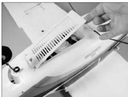
- Open the hatch from the rear of the fuselage as shown. The front of the hatch is hinged so it will not detach from the fuselage and get lost.
natural_image
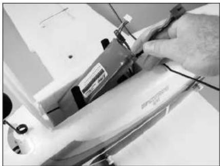
Close-up of a hand holding a white electronic device with visible circuit lines and components (no text or symbols)- Slide the battery into the battery compartment. The connector will face the back of the airplane.
natural_image
Close-up of a hand using a sewing machine to adjust or install a white fabric (no visible text or symbols)- Ensure the battery is slid all the way into the front of the battery compartment. Use the hook and loop straps to secure the battery in the fuselage.

natural_image
Close-up of a hand inserting a small electronic component into a white device (no visible text or symbols)- Close the hatch from the rear of the fuselage. Turn the battery hatch keeper 90 degrees to secure the hatch.

natural_image
Close-up of a hand adjusting a white electronic device with a grid-patterned vent (no visible text or symbols)Removing the Propeller
Required Parts
Fuselage assembly
Required Tools
Adjustable wrench
E-tips
Always remove the propeller when checking the radio system to prevent any personal injury if the motor were to start.
E·tips
Before performing any maintenance to the motor, make sure the battery has been unplugged and removed from your model to prevent injury.
- Remove the spinner cone from the spinner. It should snap away from the backplate with a little force.

natural_image
Close-up of a hand holding a small black propeller next to a white model airplane (no text or symbols visible)- Use an adjustable wrench to remove the nut from the propeller adapter. Set the nut aside so it does not get lost.

natural_image
Close-up of a hand holding a black model airplane propeller, no visible text or symbols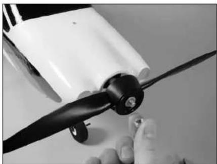
natural_image
Close-up of a hand holding a propeller with black blades, no visible text or symbols- Remove the washer and set it aside with the nut and spinner cone.

natural_image
Close-up of a hand holding a black propeller with a white sheet of paper nearby (no text or symbols visible)- Remove the spinner backplate and set it with the nut, spinner cone and washer.

natural_image
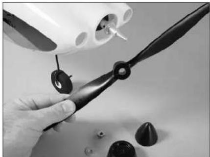
Close-up of a hand holding a black propeller with a small inset showing a dark cone (no text or symbols visible)- Slide the propeller from the propeller adapter. The installation of the propeller is the reverse of the previous steps. Make sure the nut is tightened properly so the propeller does not depart from your model during flight.
natural_image
Close-up of a hand using a black propeller to adjust small components, with no visible text or symbols.
Control Functions
Required Parts
Transmitter

We have shown the Spektrum DX5e as an example to illustrate the functions and setup of your model.
The following images are to identify the controls for your Apprentice. Both the Mode 1 and Mode 2 options are shown.

Mode 1 Transmitter

Mode 2 Transmitter
12 E-flite Apprentice PNP Assembly Manual
Centering the Control Surfaces and Checking Control Direction
Required Parts
Assembled airframe
Flight battery
Transmitter

This section is designed to help you become acquainted with the operation of the radio in correlation to the model. If a flight control moves in the incorrect direction we will instruct you how to change it in the next section. As always, read through the radio manual which explains the features of your radio system.
- Turn the radio on using the power switch on the front of the transmitter and check that the throttle stick is at its lowest position. The throttle stick needs to be in the idle/off position, otherwise the speed control will not arm in the next step. The DX5e transmitter features digital trims, so they should be centered when the transmitter is powered on.

- Plug the EC3 connector on the flight battery into the speed control. You will hear a series of beeps or tones when you plug the battery in. During this process it is normal for the prop to pulse slightly as the ESC powers up. Please ensure you are not in line with the prop or in front of it during power up.

natural_image
Close-up of hands installing or adjusting a cable or cable component on a white surface (no visible text or symbols)
Always use extreme caution around the propeller when the motor battery is plugged in. A spinning propeller can cause serious damage or injury.
It is always best to stay behind the propeller and keep it away from loose objects when the battery and speed control are connected.
When the battery is connected, you will hear one low long tone to indicate startup, then the respective number of medium-length mid tones to indicate the cell count or a musical tone, followed by three rising tones to indicate the controller is armed. For more information on your speed control, refer to the included instructions.
The following steps will ensure your flight controls are centered for the first flight.
CHECKING The ELEVATOR (MODE 2)
- Center the elevator stick. This is the right stick on the transmitter. The elevator should not be deflected up or down, but should be flat with the horizontal stabilizer when viewed from the side. If the elevator is deflected up or down you will need to push the silicone keeper back off the clevis, onto the pushrod. This will enable you to open the clevis up and remove it from the control horn. Once removed, screw the clevis in or out to get the elevator to line up with the stab.

natural_image
Close-up of a white model airplane with black and white wing accents, no visible text or symbols
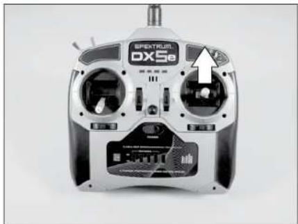
- Check the movement of the elevator with the radio system. Pulling the elevator/aileron stick (right stick on the Mode 2 transmitter) back will make the airplane elevator move up.

natural_image
Front view of a SPEATRUN DX5e remote control device with visible ports and buttons (no readable text or symbols)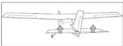
natural_image
Line drawing of a small airplane with directional arrows indicating flight or movement (no text or symbols)- Check the movement of the elevator with the radio system. Pushing the elevator/aileron stick forward will make the airplane elevator move down on the Mode 2 transmitter.
natural_image
Close-up of a metallic SPECTRJ DX5e remote control device with visible dials and buttons (no readable text beyond branding)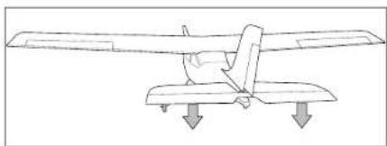
natural_image
Line drawing of a small aircraft on a flat roof with two downward arrows indicating flight or landing points (no text or symbols)CHECKING The ELEVATOR (MODE 1)
- Center the elevator stick. This is the left stick on the transmitter. The elevator should not be deflected up or down, but should be flat with the horizontal stabilizer when viewed from the side. If the elevator is deflected up or down you will need to push the silicone keeper back off the clevis, onto the pushrod. This will enable you to open the clevis up and remove it from the control horn. Once removed, screw the clevis in or out to get the elevator to line up with the stab.

natural_image
Close-up of a white and black model airplane with visible tail fins and branding (no readable text or symbols)
- Check the movement of the elevator with the radio system. Pulling the elevator/rudder stick (left stick on the Mode 1 transmitter) back will make the airplane elevator move up.

natural_image
Front view of a SPECTRUT DX5e remote control device with visible ports and an arrow pointing to the left side (no text or symbols on the device body)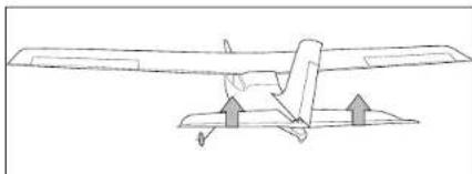
natural_image
Line drawing of a propeller airplane with directional arrows indicating flight or movement (no text or symbols)- Check the movement of the elevator with the radio system. Pushing the elevator/rudder stick forward will make the airplane elevator move down on the Mode 1 transmitter.

natural_image
Front view of a SPECTRUM DXSe remote control device with visible ports and antenna (no readable text or symbols)
natural_image
Line drawing of a propeller airplane on a platform with downward arrows indicating motion (no text or symbols)CHECKING The RUDDER (MODE 1 AND 2)
- Mode 1 (Rudder/Elevator on left stick): Center the rudder stick. Thread the clevis in or out on the rudder pushrod until the rudder is aligned with the fin as shown. Mode 2 (Rudder/Throttle on left stick): Confirm the rudder stick is in the down/throttle off position. Thread the clevis in or out on the rudder pushrod until the rudder is aligned with the fin as shown.

natural_image
Top-down view of a small aircraft on display with visible landing gear and wheels (no text or symbols)
- Check the movement of the rudder using the transmitter. When the rudder/throttle stick (left side of the transmitter) is moved right, the rudder should also move right.

natural_image
Front view of a SPEATRUN DX5e remote control device with visible dials and a control panel (no readable text or symbols)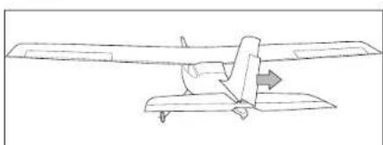
natural_image
Line drawing of a small airplane viewed from above, showing aerodynamic airflow direction (no text or symbols)E·tips When operating a Mode 2 transmitter (rudder/throttle on left stick), be very careful that the left stick is not moved forward when checking the rudder. Moving the rudder stick forward will result in the propeller spinning.
- Check the movement of the rudder using the transmitter. When the left stick is moved left, the rudder should also move left.

natural_image
Front view of a metallic SREXTRUN DX5e remote control device (no visible text or symbols on body)
natural_image
Line drawing of a small airplane in flight, showing aerodynamic components and fuselage (no text or symbols)CHECKING The STEERING TRIM (MODE 1 AND 2)

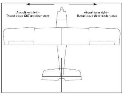
Checking the steering trim must be done after the aircraft has been flown and the rudder trimmed for straight flight at the transmitter. The steering trim is a mechanical adjustment and should never be corrected using the rudder trim at the transmitter.
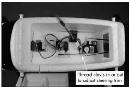
- Once the rudder has been trimmed for straight flight, you can now adjust the steering trim of your Apprentice. Taxi the aircraft to determine if it turns left or right when the rudder stick is centered. Do not change the rudder trim at the transmitter. If the aircraft turns right, thread the clevis IN at the rudder servo, which will shorten the steering linkage. If the aircraft turns left, thread the clevis OUT at the rudder servo, which will lengthen the steering linkage. Adjust until the aircraft will taxi in a straight line without any rudder control inputs.
CHECKING THE AILERONS (MODE 1 AND 2)
- Center the aileron stick. Thread the clevis in or out on the aileron pushrod until the ailerons are aligned with the wing as shown.
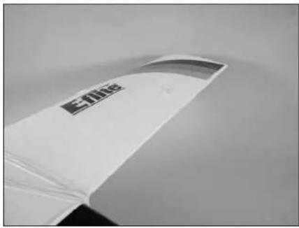

- Check the movement of the aileron using the transmitter. When the elevator/aileron stick (Mode 2 transmitter) or throttle/aileron stick (Mode 1 transmitter) is moved right, the right aileron will move up and the left aileron will move down.

natural_image
Close-up of a SPECTRUS DXSe remote control device with visible dials and a sensor display (no readable text or symbols)
natural_image
Simple line drawing of a balance scale with arrows indicating direction (no text or symbols)- Check the movement of the aileron using the transmitter. When the aileron/elevator stick (Mode 2 transmitter) or the aileron/throttle stick (Mode 1 transmitter) is moved left, the left aileron will move up and the right aileron will move down.

natural_image
Front view of a SPECTRA DXSe remote control device with visible dials and a white arrow pointing to the dial (no text or symbols on the device body)
natural_image
Simple line drawing of a balance scale with upward and downward arrows indicating direction (no text or symbols)Reversing Direction of Flight Controls
If you find any control surface moving in the opposite direction of what it should, use the Servo Reversing feature of the transmitter to fix the problem. Reference your transmitter's included manual if you are unfamiliar with the servo reversing process.
- This completes the radio setup section. You may now power down your airplane and transmitter. To do this follow these steps.
A. Unplug the aircraft battery. B. Turn transmitter off.
Center of Gravity
An important part of preparing the aircraft for flight is properly balancing the model.
Caution: Do not inadvertently skip this step!
The recommended Center of Gravity (CG) location for the Apprentice is 3^1/8 to 3^3/8 (79 to 85mm) back from the leading edge of the top wing. Mark the location for the Center of Gravity on the bottom of the top wing in the center as shown.
When balancing your Apprentice, support the plane upright at the marks made on the bottom of the wing with your fingers or a commercially available balancing stand. Move the speed control and/or receiver as necessary so the model hangs level or slightly nose down. This is the correct balance point for your model.


After the first flights, the CG position can be adjusted for your personal preference.
Range Test Your Radio
Before each flying session, and especially with a new model, it is important to perform a range check. It is helpful to have another person available to assist during the range check. If you are using a Spektrum transmitter, please refer to your transmitter's manual for detailed instructions on the range check process.
O 1. With the model resting on the ground, stand 30 paces (approximately 90 feet) away from the model.
2. Face the model with the transmitter in your normal flying position. Be sure the throttle is in the full down position and plug the flight battery into the speed control.
3. As you move the controls, watch to be sure the airplane's motor and controls operate smoothly. You should have total control of the model at 30 paces (90 feet).

- If control issues exist, call the Horizon Support Team at 1 877 504 0233 or go to horizonhobby.com to find a local Spektrum distributor in your country for service.
Setting the Control Throws
Required Parts
Transmitter
Assembled airframe
Charged flight battery
Required Tools and Adhesives
Ruler
This section will help you set your control throws to the factory settings.

Measurements are taken at the widest point on the surface.
These are general guidelines measured from our own flight tests. You can experiment with different rates to match your preferred style of flying. Adjusting of the control throws on the Apprentice 1.5e is not as critical as it is on other models. The measurements given in this section are approximations and a place to get close to when replacing parts and resetting control throws. The location of the pushrod or clevis on the servo arm and control horn of the flight control surface are given as they come set from the factory. With this information you should be able to attain settings that will be very close to the originals and deliver the flight performance you have come to expect from the Apprentice.
- Turn the radio on using the power switch on the front of the transmitter and check that the throttle stick is at its lowest position. The throttle stick needs to be in the idle/off position, otherwise the speed control will not arm in the next step. Confirm that the aileron, elevator and rudder trims are centered when the transmitter is powered on. If your transmitter features model memory, it is a good idea to reset the selected model at this time to ensure any previous programming has been cleared. The Spektrum DX5e is shown for reference only.

natural_image
Front view of a Spectrum DX58 remote control device with visible dials and a labeled 'Switch' button (no other text or symbols)- 2. Plug the motor battery into the speed control.

natural_image
Close-up of hands installing or adjusting a component on a white surface (no visible text or symbols)E-tips
Always use extreme caution around the propeller when the motor battery is plugged in. A spinning propeller can cause serious damage or injury. It is always best to stay behind the propeller and keep it away from loose objects when the battery and speed control are connected.
ELEVATOR ThROW
- Use a ruler to check the control throws on your elevator. The dimensions are shown below. For your reference the elevator pushrod is set up in the following holes: The outside hole on the elevator control horn and the fourth hole in on the elevator servo arm.
Low Rate: 3/8-inch (9mm) (Up and Down)

High Rate: 3/4-inch (19mm) (Up and Down)

RUDDER ThROW
- Use a ruler to check the control throws on your rudder. The dimensions are shown below. For your reference the rudder pushrod is set up in the following holes: the outside hole on the rudder control horn and the outside hole on the rudder servo arm.
Low Rate: 1/2-inch (14mm) (Right and Left)

natural_image
Side view of a small aircraft on a tarmac with measurement annotations (1/2-inch, 14mm) visible, no readable text or symbols beyond the measurement label.High Rate: 1 -inch (25mm) (Up and Down)

natural_image
Top-down view of a small aircraft on a tarmac with markings indicating 1-inch (25mm) and no visible text or symbols beyond the measurement label.AILERON THROW
- Use a ruler to check the control throws on the ailerons. The dimensions are shown below. For your reference the aileron pushrods are set up in the following holes: the outside hole on the aileron control horn and the outside hole on the aileron servo arm.
Low Rate: 3/8-inch (9mm) (Up and Down)

High Rate: 5/8-inch (16mm) (Up and Down)

- Once all the control throws have been set, make sure to slide the clevis retainers over the clevises to prevent them from opening accidentally.
natural_image
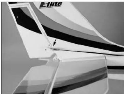
Close-up of a jet engine component with visible blade and mounting bracket (no text or symbols)- For your reference, the nose wheel steering pushrod is set up in the following holes: the fixed position hole on the nose wheel steering arm and the outside hole on the rudder servo arm.
Installing the Propeller
Required Parts
Fuselage assembly Propeller Propeller nut Propeller washer Spinner cone Spinner backplate Washer
Required Tools
Adjustable wrench
E-tips
Before performing any maintenance to the motor, make sure the battery has been unplugged and removed from your model to prevent injury.
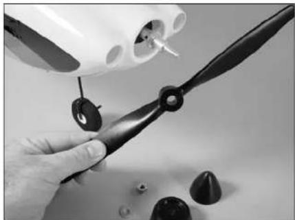
O 1. Slide the propeller on the propeller adapter.
natural_image
Close-up of a hand using a black propeller to adjust mechanical parts (no visible text or symbols)- Slide the spinner backplate on the propeller adapter.

natural_image
Close-up of a hand holding a black propeller with a small cone-shaped object nearby (no text or symbols visible)- 3. Install the washer on the propeller shaft.
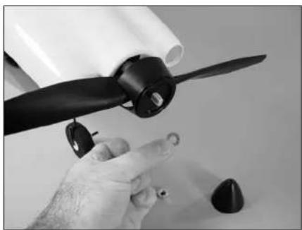
natural_image
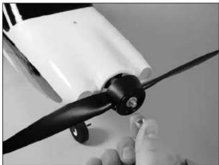
Close-up of a hand holding a black propeller with a white paper roll nearby (no text or symbols visible)- Thread the nut on the propeller adapter. Use an adjustable wrench to tighten the nut. Make sure the nut is tightened properly so the propeller does not depart from your model during flight.
natural_image
Close-up of a hand holding a black propeller airplane, no visible text or symbols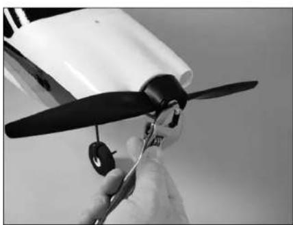
natural_image
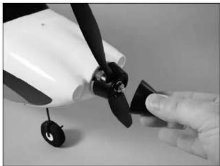
Close-up of a hand holding a black propeller airplane, no visible text or symbols- Snap the spinner cone on the spinner backplate. It should snap on the backplate using a little force.
natural_image
Close-up of a hand holding a small propeller next to a white model airplane (no visible text or symbols)Flying Your Apprentice
It is strongly recommended for your first flights to search out the assistance of a qualified instructor, who will help you through your first flights and assist you in the basics of Radio Controlled flight. Please note, the Apprentice is NOT a park flyer. It is recommended that the airplane only be flown at a flying field, where there is ample room to fly, as the Apprentice can cover ground very quickly. You can find this guidance at your local hobby dealer's store. Your Apprentice is capable of flying in winds up to 15 mph but, for flight training, it is recommended to fly in the lightest wind possible. You will need to ensure your battery is fully charged and the model is set up accordingly for your first flight. Do not attempt to fly the model on a partially charged battery.
Safety Precautions
This is a sophisticated hobby Product and not a toy. It must be operated with caution and common sense and requires some basic mechanical ability. Failure to operate this Product in a safe and responsible manner could result in injury or damage to the Product or other property. This Product is not intended for use by children without direct adult supervision. The Product manual contains instructions for safety, operation and maintenance. It is essential to read and follow all the instructions and warnings in the manual, prior to assembly, setup or use, in order to operate correctly and avoid damage or injury.
Safety Do's and Don'ts for Pilots
• Check all control surfaces prior to each takeoff.
- Do not fly your model near spectators, parking areas or any other area that could result in injury to people or damage of property.
- Do not fly during adverse weather conditions. Poor visibility can cause disorientation and loss of control of your aircraft. Strong winds can cause similar problems.
- Do not take chances. If at any time during flight you observe any erratic or abnormal operation, land immediately and do not resume flight until the cause of the problem has been ascertained and corrected. Safety can never be taken lightly.
• Do not fly near power lines.
Warranty Information
WARRANTY PERIOD
Exclusive Warranty- Horizon Hobby, Inc., (Horizon) warranties that the Products purchased (the "Product") will be free from defects in materials and workmanship at the date of purchase by the Purchaser.
LIMITED WARRANTY
(a) This warranty is limited to the original Purchaser ("Purchaser") and is not transferable. REPAIR OR REPLACEMENT AS PROVIDED UNDER THIS WARRANTY IS THE EXCLUSIVE REMEDY OF THE PURCHASER. This warranty covers only those Products purchased from an authorized Horizon dealer. Third party transactions are not covered by this warranty. Proof of purchase is required for warranty claims. Further, Horizon reserves the right to change or modify this warranty without notice and disclaims all other warranties, express or implied.
(b) Limitations- HORIZON MAKES NO WARRANTY OR REPRESENTATION, EXPRESS OR IMPLIED, ABOUT NON-INFRINGEMENT, MERCHANTABILITY OR FITNESS FOR A PARTICULAR PURPOSE OF THE PRODUCT. THE PURCHASER ACKNOWLEDGES THAT THEY ALONE HAVE DETERMINED THAT THE PRODUCT WILL SUITABLY MEET THE REQUIREMENTS OF THE PURCHASER'S INTENDED USE.
(c) Purchaser Remedy- Horizon's sole obligation hereunder shall be that Horizon will, at its option, (i) repair or (ii) replace, any Product determined by Horizon to be defective. In the event of a defect, these are the Purchaser's exclusive remedies. Horizon reserves the right to inspect any and all equipment involved in a warranty claim. Repair or replacement decisions are at the sole discretion of Horizon. This warranty does not cover cosmetic damage or damage due to acts of God, accident, misuse, abuse, negligence, commercial use, or modification of or to any part of the Product. This warranty does not cover damage due to improper installation, operation, maintenance, or attempted repair by anyone other than Horizon. Return of any goods by Purchaser must be approved in writing by Horizon before shipment.
DAMAGE LIMITS
HORIZON SHALL NOT BE LIABLE FOR SPECIAL, INDIRECT OR CONSEQUENTIAL DAMAGES, LOSS OF PROFITS OR PRODUCTION OR COMMERCIAL LOSS IN ANY WAY CONNECTED WITH THE PRODUCT, WHETHER SUCH CLAIM IS BASED IN CONTRACT, WARRANTY, NEGLIGENCE, OR STRICT LIABILITY. Further, in no event shall the liability of Horizon exceed the individual price of the Product on which liability is asserted. As Horizon has no control over use, setup, final assembly, modification or misuse, no liability shall be assumed nor accepted for any resulting damage or injury. By the act of use, setup or assembly, the user accepts all resulting liability.
If you as the Purchaser or user are not prepared to accept the liability associated with the use of this Product, you are advised to return this Product immediately in new and unused condition to the place of purchase.
Law: These Terms are governed by Illinois law (without regard to conflict of law principles).
SAFETY PRECAUTIONS
This is a sophisticated hobby Product and not a toy. It must be operated with caution and common sense and requires some basic mechanical ability. Failure to operate this Product in a safe and responsible manner could result in injury or damage to the Product or other property. This Product is not intended for use by children without direct adult supervision. The Product manual contains instructions for safety, operation and maintenance. It is essential to read and follow all the instructions and warnings in the manual, prior to assembly, setup or use, in order to operate correctly and avoid damage or injury.
QUESTIONS, ASSISTANCE, AND REPAIRS
Your local hobby store and/or place of purchase cannot provide warranty support or repair. Once assembly, setup or use of the Product has been started, you must contact Horizon directly. This will enable Horizon to better answer your questions and service you in the event that you may need any assistance. For questions or assistance, please direct your email to productsupport@horizonhobby.com, or call 877.504.0233 toll free to speak to a service technician.
INSPECTION OR REPAIRS
If this Product needs to be inspected or repaired, please call for a Return Merchandise Authorization (RMA). Pack the Product securely using a shipping carton. Please note that original boxes may be included, but are not designed to withstand the rigors of shipping without additional protection. Ship via a carrier that provides tracking and insurance for lost or damaged parcels, as Horizon is not responsible for merchandise until it arrives and is accepted at our facility. A Service Repair Request is available at www.horizonhobby.com on the "Support" tab. If you do not have internet access, please include a letter with your complete name, street address, email address and phone number where you can be reached during business days, your RMA number, a list of the included items, method of payment for any non-warranty expenses and a brief summary of the problem. Your original sales receipt must also be included for warranty consideration. Be sure your name, address, and RMA number are clearly written on the outside of the shipping carton.
WARRANTY INSPECTION AND REPAIRS
To receive warranty service, you must include your original sales receipt verifying the proof-of-purchase date. Provided warranty conditions have been met, your Product will be repaired or replaced free of charge. Repair or replacement decisions are at the sole discretion of Horizon Hobby.
NON-WARRANTY REPAIRS
Should your repair not be covered by warranty the repair will be completed and payment will be required without notification or estimate of the expense unless the expense exceeds 50% of the retail purchase cost. By submitting the item for repair you are agreeing to payment of the repair without notification. Repair estimates are available upon request. You must include this request with your repair. Non-warranty repair estimates will be billed a minimum of 1/2 hour of labor. In addition you will be billed for return freight. Please advise us of your preferred method of payment. Horizon accepts money orders and cashiers checks, as well as Visa, MasterCard, American Express, and Discover cards. If you choose to pay by credit card, please include your credit card number and expiration date. Any repair left unpaid or unclaimed after 90 days will be considered abandoned and will be disposed of accordingly. Please note: non-warranty repair is only available on electronics and model engines.
United States:
Electronics and engines requiring inspection or repair should be shipped to the following address:
Horizon Service Center
4105 Fieldstone Road
Champaign, Illinois 61822
All other Products requiring warranty inspection or repair should be shipped to the following address:
Horizon Product Support
4105 Fieldstone Road
Champaign, Illinois 61822
Please call 877-504-0233 or e-mail us at productsupport@horizonhobby.com with any questions or concerns regarding this product or warranty.
United Kingdom:
Electronics and engines requiring inspection or repair should be shipped to the following address:
Horizon Hobby UK
Units 1-4 Ployters Rd
Staple Tye
Harlow, Essex
CM18 7NS
United Kingdom
Please call +44 (0) 1279 641 097 or e-mail us at sales@horizonhobby.co.uk with any questions or concerns regarding this product or warranty.
Germany:
Electronics and engines requiring inspection or repair should be shipped to the following address:
Please call +49 4121 46199 66 or e-mail us at service@horizonhobby.de with any questions or concerns regarding this product or warranty.
CE Compliance Information for the European Union
INSTRUCTIONS FOR DISPOSAL OF WEEE BY USERS IN THE EUROPEAN UNION
This product must not be disposed of with other waste. Instead, it is the user's responsibility to dispose of their waste equipment by handling it over to a designated collection point for the recycling of waste electrical and electronic equipment. The separate collection and recycling of your waste equipment at the time of disposal will help to conserve natural resources and ensure that it is recycled in a manner that protects human health and the environment. For more information about where you can drop off your waste equipment for recycling, please contact your local city office, your household waste disposal service or where you purchased the product.

Age Recommendation: 14 years or over. Not a toy. Not intended for use by children without direct adult supervision.
2009 Official Academy of Model Aeronautics Safety Code
GENERAL
- A model aircraft shall be defined as a non-human-carrying device capable of sustained flight in the atmosphere. It shall not exceed limitations established in this code and is intended to be used exclusively for recreational or competition activity.
- The maximum takeoff weight of a model aircraft, including fuel, is 55 pounds, except for those flown under the AMA Experimental Aircraft Rules.
- I will abide by this Safety Code and all rules established for the flying site I use. I will not willfully fly my model aircraft in a reckless and/or dangerous manner.
- I will not fly my model aircraft in sanctioned events, air shows, or model demonstrations until it has been proven airworthy.
- I will not fly my model aircraft higher than approximately 400 feet above ground level, when within three (3) miles of an airport without notifying the airport operator. I will yield the right-of-way and avoid flying in the proximity of full-scale aircraft, utilizing a spotter when appropriate.
- I will not fly my model aircraft unless it is identified with my name and address, or AMA number, inside or affixed to the outside of the model aircraft. This does not apply to model aircraft flown indoors.
-
I will not operate model aircraft with metal-blade propellers or with gaseous boosts (other than air), nor will I operate model aircraft with fuels containing tetranitromethane or hydrazine.
-
I will not operate model aircraft carrying pyrotechnic devices which explode burn, or propel a projectile of any kind. Exceptions include Free Flight fuses or devices that burn producing smoke and are securely attached to the model aircraft during flight. Rocket motors up to a G-series size may be used, provided they remain firmly attached to the model aircraft during flight. Model rockets may be flown in accordance with the National Model Rocketry Safety Code; however, they may not be launched from model aircraft. Officially designated AMA Air Show Teams (AST) are authorized to use devices and practices as defined within the Air Show Advisory Committee Document.
- I will not operate my model aircraft while under the influence of alcohol or within eight (8) hours of having consumed alcohol.
- I will not operate my model aircraft while using any drug which could adversely affect my ability to safely control my model aircraft.
- Children under six (6) years old are only allowed on a flightline or in a flight area as a pilot or while under flight instruction.
- When and where required by rule, helmets must be properly worn and fastened. They must be OSHA, DOT, ANSI, SNELL or NOCSAE approved or comply with comparable standards.
RADIO CONTROL
- All model flying shall be conducted in a manner to avoid over flight of unprotected people.
-
I will have completed a successful radio equipment ground-range check before the first flight of a new or repaired model aircraft.
-
I will not fly my model aircraft in the presence of spectators until I become a proficient flier, unless I am assisted by an experienced pilot.
- At all flying sites a line must be established, in front of which all flying takes place. Only personnel associated with flying the model aircraft are allowed at or in front of the line. In the case of airshows demonstrations straight line must be established. An area away from the line must be maintained for spectators. Intentional flying behind the line is prohibited.
- I will operate my model aircraft using only radio-control frequencies currently allowed by the Federal Communications Commission (FCC). Only individuals properly licensed by the FCC are authorized to operate equipment on Amateur Band frequencies.
- I will not knowingly operate my model aircraft within three (3) miles of any preexisting flying site without a frequency-management agreement. A frequency management agreement may be an allocation of frequencies for each site, a day-use agreement between sites, or testing which determines that no interference exists. A frequency-management agreement may exist between two or more AMA chartered clubs, AMA clubs and individual AMA members, or individual AMA members. Frequency-management agreements, including an interference test report if the agreement indicates no interference exists, will be signed by all parties and copies provided to AMA Headquarters.
-
With the exception of events flown under official AMA rules, no powered model may be flown outdoors closer than 25 feet to any individual, except for the pilot and located at the flightline.
-
Under no circumstances may a pilot or other person touch a model aircraft in flight while it is still under power, except to divert it from striking an individual.
- Radio-controlled night flying is limited to low-performance model aircraft (less than 100 mph). The model aircraft must be equipped with a lighting system which clearly defines the aircraft's attitude and direction at all times.
- The operator of a radio-controlled model aircraft shall control it during the entire flight, maintaining visual contact without enhancement other than by corrective lenses that are prescribed for the pilot. No model aircraft shall be equipped with devices which allow it to be flown to a selected location which is beyond the visual range of the pilot.
Declaration of Conformity
Horizon Hobby, Inc.
4105 Fieldstone Road
Champaign, IL 61822 USA
Declaration of Conformity
(in accordance with ISO/IEC 17050-1)
No. HH20081209
Product(s): E-flite Apprentice PNP
Item Number(s): EFL2900, EFL2900i
Equipment class: 1
The object of declaration described above is in
conformity with the requirements of the specifications
listed below, following the provisions of the European
R&TTE directive 1999/5/EC:
EN 301 489-1 v.1.6.1 General EMC requirements
Signed for and on behalf of:
Horizon Hobby, Inc.
Champaign, IL USA
DEC 9, 2008
Steven A. Hall

Vice President
International Operations and Risk Management
Horizon Hobby, Inc.
Building and Flying Notes:

ADVANCING ELECTRIC FLIGHT
HORIZON
H O B B Y
© 2009 Horizon Hobby, Inc.
4105 Fieldstone Road
Champaign, Illinois 61822
(877) 504-0233
horizonhobby.com
E-fliteRC.com


- Specifications
- Table of Contents
- Introduction
- Important Warranty Information
- Using the Manual
- Product Registration
- Contents of Kit/Parts Layout
- Required Radio Equipment
- Complete Radio System
- Or Purchase Separately
- Or
- Battery
- Charger
- Optional
- Required Tools and Adhesives
- Tools & Equipment
- Optional Accessories
- Note on Lithium Polymer Batteries
- Charging the Flight Battery
- AR500 Receiver Installation
- Required Parts
- AR6200 Receiver Installation
- Tail Installation
- Required Tools
- Landing Gear Installation
- E-tips
- Wing Installation
- Battery Installation
- Removing the Propeller
- E·tips
- Control Functions
- Centering the Control Surfaces and Checking Control Direction
- CHECKING The ELEVATOR (MODE 2)
- CHECKING The ELEVATOR (MODE 1)
- CHECKING The RUDDER (MODE 1 AND 2)
- CHECKING The STEERING TRIM (MODE 1 AND 2)
- CHECKING THE AILERONS (MODE 1 AND 2)
- Reversing Direction of Flight Controls
- Center of Gravity
- Range Test Your Radio
- Setting the Control Throws
- ELEVATOR ThROW
- RUDDER ThROW
- AILERON THROW
- Installing the Propeller
- Flying Your Apprentice
- Safety Precautions
- Safety Do's and Don'ts for Pilots
- Warranty Information
- WARRANTY PERIOD
- LIMITED WARRANTY
- DAMAGE LIMITS
- QUESTIONS, ASSISTANCE, AND REPAIRS
- INSPECTION OR REPAIRS
- WARRANTY INSPECTION AND REPAIRS
- NON-WARRANTY REPAIRS
- United States:
- United Kingdom:
- Germany:
- CE Compliance Information for the European Union
- INSTRUCTIONS FOR DISPOSAL OF WEEE BY USERS IN THE EUROPEAN UNION
- Official Academy of Model Aeronautics Safety Code
- GENERAL
- RADIO CONTROL
- Declaration of Conformity
Brand : E-flite
Model : Apprentice 15e PNP
Category : Toy