15A2 - Desktop computer ELO - Free user manual and instructions
Find the device manual for free 15A2 ELO in PDF.


| Product Type | All-in-One Desktop Computer |
| Brand | Elo |
| Model | 15A2 |
| Display Size | 15.6 inches |
| Display Type | LED-backlit LCD with projected capacitive touch |
| Touch Technology | Projected capacitive, 10-point multi-touch |
| Resolution | 1920 x 1080 (Full HD) |
| Processor | Intel Celeron N3350 (dual-core, 1.1 GHz) |
| Memory | 4 GB DDR3L SO-DIMM |
| Storage | 64 GB eMMC |
| Operating System | Windows 10 IoT Enterprise (or Windows 10 Pro) |
| Connectivity | Wi-Fi 802.11ac, Bluetooth 4.2, Ethernet (RJ-45) |
| Ports | 2 x USB 3.0, 2 x USB 2.0, 1 x HDMI-out, 1 x Audio combo jack |
| Power Supply | External AC adapter, 100-240V, 50/60Hz, 60W |
| Dimensions (W x H x D) | 14.5 x 12.5 x 2.5 inches (368 x 318 x 64 mm) |
| Weight | 6.2 lbs (2.8 kg) |
| Mounting | VESA 75 x 75 mm compatible |
| Cleaning | Wipe with soft, lint-free cloth; use mild soap if needed; avoid abrasive cleaners |
| Safety | Do not disassemble, avoid liquids, use only supplied power adapter |
| Spare Parts | AC adapter, stand, screen protectors available from Elo |
| Warranty | 3 years limited warranty |
Frequently Asked Questions - 15A2 ELO
User questions about 15A2 ELO
0 question about this device. Answer the ones you know or ask your own.
Ask a new question about this device
Download the instructions for your Desktop computer in PDF format for free! Find your manual 15A2 - ELO and take your electronic device back in hand. On this page are published all the documents necessary for the use of your device. 15A2 by ELO.
USER MANUAL 15A2 ELO
natural_image
Close-up of a green printed circuit board with two black integrated circuits, enclosed in a circular frame (no text or symbols visible)Quick Installation Guide
Installing additional RAM for the 17A2/15A2


North America Eo Touch System 301 Contributor Drive Meno Park, DA 94025 www.alobouch.com
www.elotouch.com
Elo Technical Support Online self-help: www.sicltech.com/gewshag.co.uk Technical Support contacts in your region: www.sicltech.com/gewshag.co.uk

Europe Tel +32 (0)16 35 21 02 Fax +32 (0)16 35 21 01 eosales@akcbuch.com

Asia-Pacific Tel: +81 (45) 478-2151 Fax: +81 (45) 478-2190 www.tps.co/p
For current Elo news, product updates and announcements, register to receive our TouchMonitor newsletter at www.elolouch.com/go/news


Tyco Electronics
Our commitment. Your advantage.
Note: ●Always handle the component by its edges.
- Installer must be electrically grounded while performing installation steps.
Note on adding/removing memory modules:
Be careful, as improper installation or removal of a memory module can cause harmful damage to your touchcomputer. Only install memory modules that are compatible with your touchcomputer. The module packaged with this accessory kit meets the requirements for this touchcomputer.
Be careful when handling a memory module, as ESD can damage the module.
natural_image
Close-up of a mechanical component with a yellow arrow pointing to a circular feature (no text or symbols visible)▶▶▶
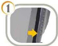
Turn off power to the touchcomputer and unplug the power adapter from the unit.
natural_image
Close-up of a mechanical device with yellow arrows indicating directional movement (no text or symbols)▶▶▶
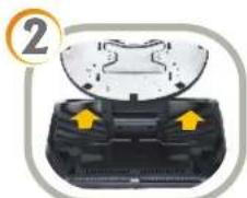
Turn touchcomputer upside down and take off the back cover insert
natural_image
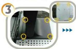
Close-up of a perforated metal panel with mounting holes and a close-up view of a mechanical component (no text or symbols visible)Remove the four screws connecting the stand to the chassis. Once these screws are removed, the stand will come off. Then remove the four screws on the chassis.
natural_image
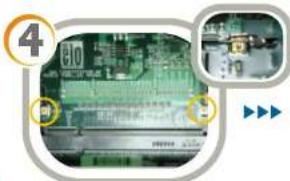
Close-up of a green circuit board with electronic components and a monitor, no visible text or symbolsTo remove an existing memory module, pull the two metal latches away from the modules until the module is released. The module should tilt up and then can be safely removed.
▶▶▶
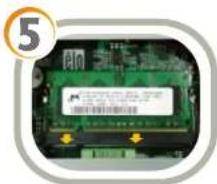
Align the pins of the memory module with the connector at an angle and push it in until the pins are in place. Then push the memory module down until it clicks. If it clicks, then it means the module was installed successfully.
natural_image
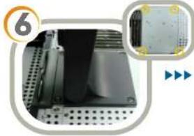
Close-up of a mechanical component with perforated plate and a close-up view showing a textured surface (no text or symbols)Reinstall the four screws to close the chassis and then reinstall the stand using the screws removed in Step 3.
natural_image
Close-up of a mechanical device with yellow arrows indicating features, no visible text or symbols▶▶▶
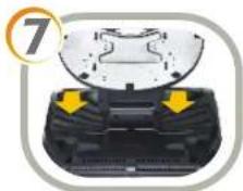
Replace the back cover insert.
natural_image
Close-up of a computer mouse with a yellow arrow pointing to the screen area (no text or symbols visible)▶▶▶
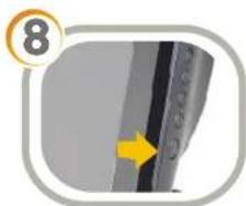
Reconnect the power adapter and power on the touchcomputer. You may use the operating system to verify that the additional memory was installed properly.
Brand : ELO
Model : 15A2
Category : Desktop computer