
IK-WB16A - Security Camera TOSHIBA - Free user manual and instructions
Find the device manual for free IK-WB16A TOSHIBA in PDF.


| Product Type | Security Camera |
| Brand | Toshiba |
| Model | IK-WB16A |
| Dimensions | Approximately 7.3 x 7.3 x 14.8 cm (2.9 x 2.9 x 5.8 in) |
| Weight | Approximately 500 g (1.1 lb) |
| Power Supply | 12V DC or PoE (Power over Ethernet) |
| Video Resolution | Up to 1920 x 1080 (1080p) at 30 fps |
| Lens | Fixed, 3.6 mm or 4 mm, F2.0 |
| Night Vision | IR LEDs up to 20 meters (65 ft) |
| Network | Ethernet 10/100 Mbps, Wi-Fi not specified |
| Mounting | Wall or ceiling mount bracket included |
| Operating Temperature | -10°C to 50°C (14°F to 122°F) |
| Ingress Protection | IP66 weatherproof rating |
| Motion Detection | Built-in, with configurable sensitivity and zones |
| Audio | Built-in microphone and speaker (two-way audio support) |
| Storage | microSD card slot (max 128 GB) or NVR |
| Protocols | IPv4, IPv6, TCP/IP, UDP, HTTP, HTTPS, RTSP, ONVIF |
| Warranty | 1 year limited |
| Maintenance | Clean lens with soft dry cloth; avoid solvents |
| Safety | CE, FCC, RoHS compliant |
| Spare Parts | Replacement brackets, power adapter available; contact support |
Frequently Asked Questions - IK-WB16A TOSHIBA
User questions about IK-WB16A TOSHIBA
0 question about this device. Answer the ones you know or ask your own.
Ask a new question about this device
Download the instructions for your Security Camera in PDF format for free! Find your manual IK-WB16A - TOSHIBA and take your electronic device back in hand. On this page are published all the documents necessary for the use of your device. IK-WB16A by TOSHIBA.
USER MANUAL IK-WB16A TOSHIBA
Leading Innovation >>>
NETWORK CAMERA
Model: IK-WB16A / IK-WB16A-W
User's Manual

natural_image
Close-up of a white cylindrical device with a lens and 'TOSHIBA' logo, no visible text or symbols beyond the brand name.IK-WB16A IK-WB16A-W

natural_image
Close-up of a white cylindrical device with a lens and two protruding wires, labeled 'TOSHIBA' (no additional text or symbols visible)For information on our latest products and peripheral devices, refer to the following Website:
■ http://www.toshibasecurity.com
If the URL changes, refer to the Toshiba website (http://www.toshiba.com/).
Introduction......4
Important Safeguards....6
Important Safeguards (Cont.) 9
Notes on Use and Installation.... 10
Precautions for Use....11
AC Adapter 13
Package Contents 15
Physical Description 16
Installation 19
Hardware Installation....19
Network Deployment....19
Software Installation 23
Ready to Use....24
Accessing the Network Camera 25
Using Web Browsers 25
Using RTSP Players....27
Using 3GPP-compatible Mobile Devices....28
Main Page 29
Client Settings 33
Configuration 35
System 36
Security 38
HTTPS (Hypertext Transfer Protocol over SSL) 39
SNMP (Simple Network Management Protocol) 44
Network 45
Wireless LAN (IK-WB16A-W only) 59
DDNS 62
Access List 63
Audio and Video 66
Motion Detection 75
Camera Tampering Detection 77
Camera Control....78
Homepage Layout 81
Application 84
Recording 97
Local Storage 100
System Log 104
View Parameters 104
Maintenance....105
Troubleshooting....109
Reboot and restore....109
Audio 109
External Microphone 109
Recommended system requirements....109
Lens Focus....109
WPS (Wi-Fi Protected Setup) : IK-WB16A-W only.... 109
Specifications 110
Appearance Diagram.... 112
Technology License Notice.... 114
GNU General Public License.... 115
Introduction
FCC (USA)-INFORMATION
NOTE: This equipment has been tested and found to comply with the limits for a Class B digital device, pursuant to Part 15 of the FCC Rules. These limits are designed to provide reasonable protection against harmful interference in a residential installation. This equipment generates, uses and can radiate radio frequency energy and, if not installed and used in accordance with the instructions, may cause harmful interference to radio communications. However, there is no guarantee that interference will not occur in a particular installation. If this equipment does cause harmful interference to radio or television reception, which can be determined by turning the equipment off and on, the user is encouraged to try to correct the interference by one or more of the following measures:
- Reorient or relocate the receiving antenna.
- Increase the separation between the equipment and receiver.
- Connect the equipment into an outlet on a circuit different from that to which the receiver is connected.
- Consult the dealer or an experienced radio/TV technician for help.
Shielded interface cables must be used in order to comply with emission limits.
USER-INSTALLER CAUTION: Your authority to operate this FCC verified equipment could be voided if you make changes or modifications not expressly approved by the party.
Thank you for purchasing the IK-WB16A/IK-WB16A-W Network Camera. Before you start using the camera, read this User's Manual carefully to ensure correct usage. Once you have finished reading this User's Manual, keep it in a convenient place for future reference.
The design, specifications, software, and User's Manual contents are subject to change without prior notice.
Terms and Trademarks
- The term "OS" is used in this User's Manual to indicate operating systems compatible with this product.
- Windows® XP: Microsoft® Windows® XP operating system
- Windows Vista®: Microsoft® Windows Vista® Business operating system
- Windows 7 : Microsoft Windows 7 Professional operating system
- The formal name of Windows is Microsoft Windows Operating System.
- Microsoft ® , Windows ® , and Windows Vista ® are trademarks or registered trademarks of Microsoft ® Corporation in the United States and other countries.
- Adobe is a registered trademark and Adobe Reader is a trademark of Adobe Systems Incorporated.
- Other product names appearing in this User's Manual may be trademarks or registered trademarks of their respective holders.

NOTE
- The performance of the network camera may vary depending on the network environment.
- When using multiple network cameras, the appropriate network switch and PC are required.
- This camera does not support MAC-PC.
Important Safeguards
1. Read Instructions
Read all the safety and operating instructions before operating the product.
2. Retain Instructions
Retain the safety instructions and user's manual for future reference.
3. Warnings
Comply with all warnings on the product and in the user's manual.
4. Follow Instructions
Follow all operating and use instructions.
5. Cleaning
Disconnect this video product from the power supply before cleaning.
6. Attachments
Do not use attachments not recommended by the video product manufacturer as they may pose safety risks.
7. Water and Moisture
Do not use this video product near water. Some examples are: near a bath tub, wash bowl, kitchen sink, or laundry tub, in a wet basement, or near a swimming pool.
8. Accessories
Do not place this video product on an unstable cart, stand, tripod, bracket or table. The video product may fall, causing serious injury to a person, or serious damage to the product. Use only with stand, tripod, bracket, or table recommended by the manufacturer, or sold with the video product. Any mounting of the product should follow the manufacturer's instructions, and should use a mounting accessory recommended by the manufacturer.
9. Ventilation
This video product should never be placed near or over a radiator or heat register. If this product is placed in a built-in installation verify that there is proper ventilation so that the camera temperature operates within the recommended temperature range.
10. Power Sources
This video product should be operated only from the type of power source indicated on the information label. If you are not sure of the type of power supply at your location, consult your product dealer.
11. Power-Cord Protection
Power cords should be routed so that they are not likely to be walked on or pinched by items placed upon or against them. Pay particular attention to cords at plugs, screws and the point where they exit the product.
12. Installation
Install this video product on a secure part of the ceiling or wall. If installed on an unsecured location, the camera could fall causing injury and damage.
13. Lightning
For additional protection on this video product during a lightning storm, or when it is left unattended and unused for long periods of time, unplug it from the wall outlet and disconnect the power supply and cable system. This will prevent damage to the video product due to lightning and power-line surges. If lightning occurs, do not touch the unit or any connected cables in order to avoid electric shock.
14. Overloading
Do not overload the power supply or extension cords as this can result in a risk of fire or electric shock.
15. Object and Liquid Entry
Never push objects of any kind into this video product through openings as they may touch dangerous electrical points or short-out parts that could result in a fire or electrical shock. Never spill liquid of any kind on the video product.
16. Servicing
Do not attempt to service this video product yourself as opening or removing covers may expose you to dangerous electrical or other hazards. Refer all servicing to qualified service personnel.
17. Damage Requiring Service
Disconnect this video product from the power supply and refer servicing to qualified service personnel under the following conditions.
a. When the power-supply cord or plug is damaged.
b. If liquid has been spilled, or objects have fallen into the video product.
c. If the video product has been submerged in water.
d. If the video product does not operate normally by following the operating instructions in the user's manual. Adjust only those controls that are covered by the user's manual as an improper adjustment of other controls may result in damage and will often require extensive work by a qualified technician to restore the video product to its normal operation.
e. If the video product has been dropped or the cabinet has been damaged.
f. When the video product exhibiting a distinct change in performance which indicates a need for service.
g. Other trouble.
18. Replacement Parts
When replacing parts be sure the service technician uses parts specified by the manufacturer or have the same characteristics as the original part. Unauthorized substitutions may result in fire, electric shock, malfunction or other hazards.
19. Safety Check
Upon completion of any service or repairs to this video product, ask the service technician to perform safety checks to determine that the video product is in proper operating condition.
20. When using a wireless LAN function (IK-WB16A-W):
- Do not use near people with heart pacemakers.
- Do not use near electronic medical equipment, or in hospitals or other medical institutions.
- Do not use inside aircraft or in places where the wireless LAN function could interfere with electromagnetic signals.
The electromagnetic interference could cause a malfunction, resulting in an accident.
21. If the use of a wireless LAN function interferes with another device's electromagnetic signals, cease use immediately.(IK-WB16A-W)
The electromagnetic interference could cause a malfunction, resulting in an accident.
Important Safeguards (Cont.)
CAUTION TO REDUCE THE RISK OF ELECTRIC SHOCK
DO NOT REMOVE COVER. NO USER SERVICEABLE PARTS INSIDE. REFER SERVICING TO QUALIFIED SERVICE PERSONNEL.

The lightning flash with arrowhead symbol, within an equilateral triangle, is intended to alert the user to the presence of uninsulated "dangerous voltage" within the product's enclosure that may be of sufficient magnitude to constitute a risk of electric shock to persons.

The exclamation point within an equilateral triangle is intended to alert the user to the presence of important operating and maintenance (servicing) instructions in the literature accompanying the appliance.
WARNING:
TO REDUCE THE RISK OF FIRE OR ELECTRIC SHOCK, DO NOT EXPOSE THIS APPLIANCE TO RAIN OR MOISTURE.
FIELD INSTALLATION MARKING:
WORDED: "THIS INSTALLATION SHOULD BE MADE BY A QUALIFIED SERVICE PERSON AND SHOULD CONFORM TO ALL LOCAL CODES."
Notes on Use and Installation
- Do not aim the camera at the sun
Never aim the camera at the sun even with the camera power off.
- Do not shoot intense light
Intense light such as a spotlight may cause a bloom or smear. A vertical stripe may appear on the screen. However, this is not a malfunction.
- Treat the camera with care
Dropping or subjecting the camera to intense vibration may cause it to malfunction.
- Avoid Volatile Liquid
Do not use volatile liquids, such as an insect spray, near the unit. Do not leave rubber or plastic products touching the unit for a long time. They will leave marks on the finish. Do not use a chemically saturated cloth.
- Never touch internal parts
Do not touch the internal parts of the camera other than the parts specified.
- Keep the camera installation away from video noise
If cables are wired near electric lighting wires or a TV set, noise may appear in images. In this event relocate cables or reinstall equipment.
- Check the ambient temperature and humidity
Avoid using the camera where the temperature is hotter or colder than the specified operating range. Doing so could affect the internal parts or cause the image quality to deteriorate. Special care is required to use the camera at high temperature and humidity.
- Caution when using the wireless LAN functions (IK-WB16A-W)
The Wireless LAN in this unit uses the 2.4 GHz waveband. If there is a similar wireless LAN in the area, or a wireless device using the 2.4 GHz waveband, or a microwave oven, the communication efficiency of this apparatus will be reduced, and may become unusable, but it is not a fault. If this happens, move the product to a location that will not cause radio interference to medical, industrial and public equipment or stop using the unit.
- Should you notice any trouble
If any trouble occurs while you are using the camera, turn off the power and contact your dealer. If you continue to use the camera when there is something wrong with it, the trouble may get worse and an unpredictable problem may occur.
Precautions for Use
Disclaimer
We disclaim any responsibility and shall be held harmless for any damages or losses incurred by the user in any of the following cases:
- Fire, earthquake or any other act of God; acts by third parties; misuse by the user, whether intentional or accidental; use under extreme operating conditions.
- Malfunction or non-function resulting in indirect, additional or consequential damages, including but not limited to loss of expected income and suspension of business activities.
- Incorrect use not in compliance with instructions in this user's manual.
- Malfunctions resulting from misconnection to other equipment.
- Repairs or modifications made by the user or caused to be made by the user and carried out by an unauthorized third party.
- Notwithstanding the foregoing, Toshiba's liabilities shall not, in any circumstances, exceed the purchase price of the product.
Copyright and Right of Portrait
There may be a conflict with the Copyright Law and other laws when a customer uses, displays, distributes, or exhibits an image picked up by the camera without permission from the copyright holder. Please also note that transfer of an image or file covered by copyright is restricted to use within the scope permitted by the Copyright Law.
Protection of Personal Information
Images taken by the camera that reveal the likeness of an individual person may be considered personal information. To disclose, exhibit or transmit those images over the internet or otherwise, consent of the person may be required.
Usage Limitation
The product is not designed for any "critical applications." "Critical applications" means life support systems, exhaust or smoke extraction applications, medical applications, commercial aviation, mass transit applications, military applications, homeland security applications, nuclear facilities or systems or any other applications where product failure could lead to injury to persons or loss of life or catastrophic property damage.
Accordingly, [Toshiba/TAIS] disclaims any and all liability arising out of the use of the product in any critical applications.
Wireless LAN and Your Health
Wireless LAN products, like other radio devices, emit radio frequency electromagnetic energy. The level of energy emitted by Wireless LAN devices however is far much less than the electromagnetic energy emitted by wireless devices like for example mobile phones.
Because Wireless LAN products operate within the guidelines found in radio frequency safety standards and recommendations, TOSHIBA believes Wireless LAN is safe for use by consumers. These standards and recommendations reflect the consensus of the scientific community and result from deliberations of panels and committees of scientists who continually review and interpret the extensive research literature.
In some situations or environments, the use of Wireless LAN may be restricted by the proprietor of the building or responsible representatives of the organization. These situations may for example include:
- Using the Wireless LAN equipment on board airplanes, or
- In any other environment where the risk of interference to other devices or services is perceived or identified as harmful.
If you are uncertain of the policy that applies on the use of wireless devices in a specific organization or environment (e.g. airports), you are encouraged to ask for authorization to use the Wireless LAN device prior to turning on the equipment.
AC Adapter
Be sure to use only the supplied AC adapter. Using a different AC adapter may cause the camera to malfunction, heat up, or catch fire. Before using the AC adapter, carefully read and observe the Important Safeguards ( → page 5) and the notes below.
- Plug the AC adapter into the 100-240V AC outlet. If inserting it into other than 100-240V AC outlet, it may result in electric shock or fire hazard.
- Do not repair, modify or disassemble the AC adapter. It may result in electric shock or fire hazard.
- Keep the blades of Plug free from any dust or dirt. Neglecting to do so may cause a fire due to deterioration of the insulation. Pull out the power plug from the outlet before cleaning the blades.
-
Do not cover or wrap the AC adapter with a cloth or place it near heating devices. It may cause fire or malfunction of the unit.
-
Protect the power cord from being:
- damaged, modified for extension, or applied heat.
- pulled, put heavy objects, or pinched.
- bent, twisted extremely, or bundle.
Neglecting to do so may cause electric shock or fire hazard.
- Do not expose this AC adapter to water.
- Install the AC adapter properly on a wall or ceiling after plugging in the AC adapter. Avoid dropping the AC adapter, failing to do so may cause serious personal injury or death.
- Do not allow the connectors on the AC adapter to come into contact with any other metal object as this may result in short circuit.
- To connect the AC adapter, firmly insert the plug end of the cable into the AC adapter jack. Do not insert the plug into other jacks as this may cause a malfunction.
- When removing the connection cable, disconnect the cable by holding its plug. Do not disconnect the cable by pulling on the cable.
- Do not drop the AC adapter or subject it to strong impact.
- Do not use the AC adapter in hot and humid places.
- Do not use the supplied AC adapter with devices other than this camera.
- Temperature increasing on the surface of the adapter is normal. Before moving the adapter to another location, unplug it from the wall outlet, and wait until its temperature decreases.
- Buzzing noises may come from inside. This does not indicate malfunction.
- Using the AC adapter near a radio, TV, cellphone, or any wireless devices/equipment may cause interference. Use the adapter at sufficient distances from these devices.
- Be sure to use the supplied AC adapter. Using different AC adapter may cause fire hazard or the camera to malfunction.
Specifications
AC adapter (DSA-20P-10)
Power source : 100-240V AC 50/60 Hz
Rated output : 12V DC, 1.5 A
Ambient temperature guaranteed for performance : 32°F to 104°F (0°C to 40°C)
Storage temperature : -4°F to 140°F (-20°C to 60°C)
Maximum external dimensions : 1.42 x 1.85 x 2.93 inches (36 x 47 x 74.5 mm) (width x height x depth)
Cord length : 72 inches (1828 mm)
Package Contents
- IK-WB16A/IK-WB16A-W

natural_image
Technical line drawing of a mechanical component with a side-view view labeled 'Back Cover' (no other text or symbols)● Antenna (IK-WB16A-W only)
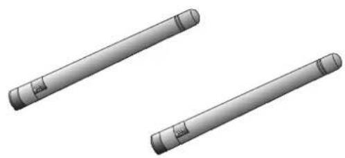
natural_image
Two cylindrical mechanical components with flanged ends, shown in 3D rendering (no text or symbols)● Screws / LAN cable and RJ45 Female/Female Coupler

natural_image
Illustration of three electronic components: a package, a small box, and a black cable with connectors (no text or symbols)- Warranty Card

natural_image
Empty white square with a thin black border (no text or symbols)- AC Adapter
Cord length: 72 inches (1828 mm)
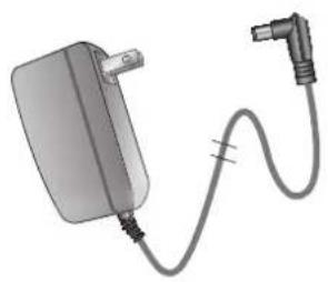
natural_image
Illustration of a charging plug connected to a cable with a power outlet (no text or symbols)● Ceiling Mount Brackets / Alignment sticker
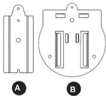
natural_image
Technical line drawings of two mechanical components labeled A and B, showing front and side views (no text or symbols beyond labels)
flowchart
graph TD
    A["Drill hole"] --> B["Adjustment Trigger"]
    C["Drill load"] --> B
    D["Drill load/Drill hole"] --> B
    B --> E["Position Indicator"]
    style A fill:#f9f,stroke:#333
    style C fill:#ccf,stroke:#333
    style D fill:#cfc,stroke:#333
● Quick Start Guide and Important Safeguards

- CD-ROM

Content: User's Manual Quick Installation Guide Installation Wizard
Physical Description
Front Panel
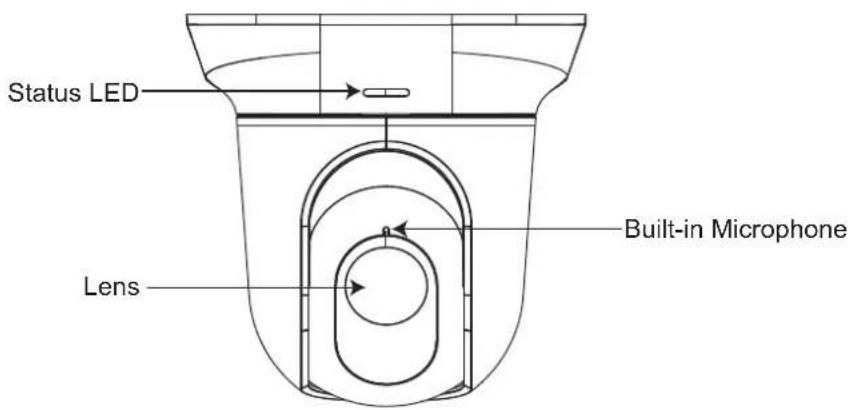
Back Panel

General I/O Terminal Block
This Network Camera provides a general I/O terminal block which is used to connect external input / output devices. The pin definitions are described below.
| Pin Name |
| 1 12V DC Output |
| 2 Digital Output |
| 3 Digital Input |
| 4 Ground |


NOTE
- 12V DC is outputted from 1-pin only when connected to a power supply.
The diagrams below apply when "Digital Input" is used for an alarm input.
| Internal Circuit | Signal Condition | |
| Digital Input |  | Active state is low.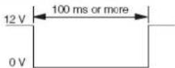 Active state is high. Active state is high.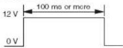 |
| Digital Output |  | MAX. 12 VDC, 400 mA |
Status LED
The LED indicates the status of the Network Camera.
| Item | LED status Description | |
| 1 | Steady Red Power on and system booting | |
| Red LED unlit Power off | ||
| 2 | Steady Red + Blinking Green every 1 sec. Network connected (heartbeat) | |
| Steady Red + Green LED unlit Network disconnected | ||
| 3 | Steady Red + Blinking Green every 2 sec. Audio mute (heartbeat) | |
| 4 | Blinking Red every 0.15 sec. + Blinking Green every 1 sec. Upgrading Firmware | |
| 5 | Blinking Red every 0.15 sec. + Blinking Green every 0.15 sec. Restore default |
WPS/Reset
This button is used dual purposes.

WPS: (IK-WB16A-W only)
Push the WPS button of your wireless access point. Press and release the WPS recessed button on the back of the camera using a paper clip or small object. The ESSID and encrypted key of the wireless access point will be sent to the camera and the wireless LAN settings are complete.
The reset button is used to reset the system or restore the factory default settings. Occasionally, resetting the system can return the camera to normal operation. If the system problems remain after resetting, restore the factory settings and install again.
Reset: Push and hold the reset button for 2 - 6 seconds using a paper clip or small object until the status LED (Green and Red) is unlit. Wait for the Network Camera to reboot.
Restore: Press and hold the recessed reset button until the status LED (Green and red) rapidly blinks. It takes about 30 seconds. Note that all settings will be restored to factory default. Upon successful restore, the status LED will blink green and red during normal operation.

Restoring the factory defaults will erase any previous settings.
SD/SDHC Card and Capacity
This network camera is compliant with microSD/SDHC 16GB / 8GB and other preceding standard SD cards for local storage.

NOTE
- There is a limit to the number of rewrites that is possible with the SD memory card. Replacing the SD memory card when performing periodic maintenance of the camera is recommended.
- Do not use 512MB and below SD memory cards.
- The camera system reserves approximately 60MB in SD memory cards. Any images are not recordable on this space.
- Carefully read the User's guide, precautions on use, and any other information supplied with a purchased memory card.
- An SD memory card can be used for repeated storage. The lifespan (number of rewrites possible) of an SD memory card is greatly affected by the capacity of the SD memory card.
- Do not use a memory card containing the data recorded by another device with the camera as this may result in the camera not functioning correctly.
- Do not modify, overwrite the data, or change the folder name of an SD memory card. It may result in the camera not to function correctly.
- If you unmount or remove the SD memory card from camera, you have to turn OFF the recording status in Recording window on page 100 and Application window on page 87.
Installation
Hardware Installation
Please verify that your product package contains all the accessories listed in the Package Contents listed on page 13. Depending on the user's application, an Ethernet cable may be needed. The Ethernet cable should meet the specs of UTP Category 5.
Hardware Installation is shown in the Quick Start Guide(QSG). Please refer to page 15 of the QSG.
Network Deployment
In this user's manual, "User" refers to whoever has access to the Network Camera, and "Administrator" refers to the person who can configure the Network Camera and grant user access to the camera.
Network Deployment is shown in the Quick Start Guide(QSG). Please refer to page 18 of the QSG.
Setting up the Network Camera over the Internet
There are several ways to set up the Network Camera over the Internet. The first way is to set up the Network Camera behind a router. The second way is to utilize a static IP. The third way is to use PPPoE.
Internet connection via a router
Before setting up the Network Camera over the Internet, make sure you have a router and follow the steps below.
- Connect your Network Camera behind a router, the Internet environment is illustrated below. Regarding how to obtain your IP address, please refer to Software Installation on page 23 for details.

flowchart
graph TD
    A["Internet"] --> B["Cable or DSL Modem"]
    B --> C["WAN (Wide Area Network)"]
    C --> D["Router IP address: from ISP"]
    D --> E["LAN (Local Area Network)"]
    E --> F["Router IP address: 192.168.0.1"]
    F --> G["IP address: 192.168.0.3\nSubnet mask: 255.255.255.0\nDefault router: 192.168.0.1"]
    G --> H["IP address: 192.168.0.2\nSubnet mask: 255.255.255.0\nDefault router: 192.168.0.1"]
    H --> I["This client PC sets up a camera and a router."]
- In this case, if the Local Area Network (LAN) IP address of your Network Camera is 192.168.0.3, please forward the following ports for the Network Camera on the router.
■ HTTP port
■ RTSP port
■ RTP port for audio
■ RTCP port for audio
■ RTP port for video
■ RTCP port for video
If you have changed the port numbers on the Network page, please open the ports accordingly on your router. For information on how to forward ports on the router, please refer to your router's user's manual.
- Determine the public IP address of your router provided by your ISP (Internet Service Provider). Use the public IP and the secondary HTTP port to access the Network Camera from the Internet. Please refer to Network Type on page 45 for details.
Internet connection with static IP
Choose this connection type if you are required to use a static IP for the Network Camera. Please refer to LAN on page 45 for details.
Internet connection via PPPoE (Point-to-Point over Ethernet)
Choose this connection type if you are connected to the Internet via a DSL Line. Please refer to PPPoE on page 46 for details.

flowchart
graph TD
    A["Internet"] --> B["ADSL Modem"]
    B --> C[" surveillance camera"]
    C --> D["Laptop"]
Set up the Network Camera through Power over Ethernet (PoE) (IK-WB16A only)
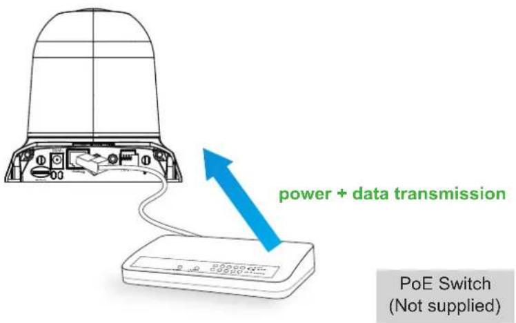
When using a PoE-enabled switch
The Network Camera is PoE-compliant, which allows it to be powered via a single Ethernet cable. If your switch/router supports PoE, refer to the following illustration to connect the Network Camera to a PoE-enabled switch/router.
When using a non-PoE switch
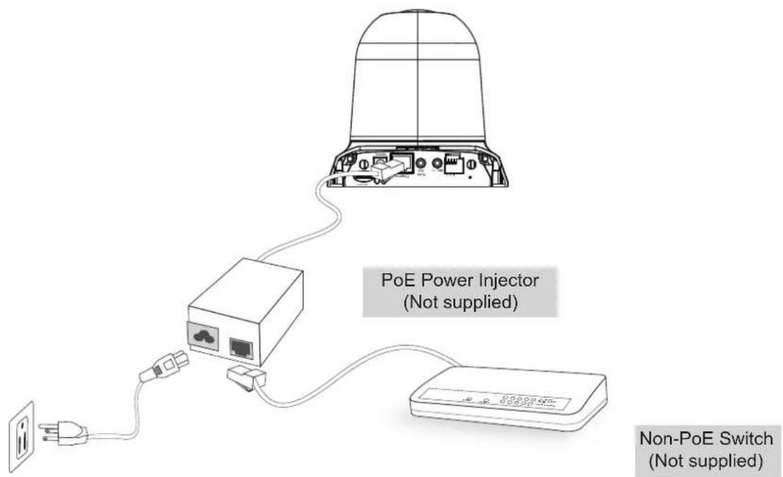
If your switch/router does not support PoE, use a PoE power injector (not supplied) to connect between the Network Camera and a non-PoE switch/router.
Set up the Network Camera through Wireless Connection (IK-WB16A-W only)
- Check the SSID and wireless security currently set on your wireless access point (AP).
- Go to IK-WB16A-W's Configuration > Wireless.
- Set in the SSID and wireless security consistent with the setting on your AP.
- Select the Wireless mode as "Infrastructure".
- Click Save. The Network Camera will reboot.
![TOSHIBA Configuration >Wireless Home System Security HTTPS SNMP Network Wireless DDNS Access list Audio and video Motion detection Camera tampering detection Camera control Homepage layout Application Recording Local storage System log View parameters Maintenance [ Basic mode ] Version: 01006 WLAN configuration 880 default Wireless mode infrastructure Channel 11 GB Security None Save](/content/2026/05/988175/images/e7fd963ccc6f1ef8d67949f1cfbc56ebecb01c2e309aaae3e9e708278bab03f3.jpg)
- Wait for the live image to refresh in your browser. Then, unplug the power cable and Ethernet cable from the Network Camera.
- Replug the power cable to the camera. The Network Camera now operates in wireless mode


NOTE
- SSID, abbreviated from Service Set Identifier, is the name assigned to the wireless network. The IK-WB16A-W's factory SSID setting is set to "default".
- Select "Ad-Hoc" wireless mode if you want the IK-WB16A-W to communicate without using an AP or wireless router.
- Wireless networking has many security issues. It's very important that you define effective wireless security policies that guard against unauthorized access to important resources.
- For detailed information ablut wireless connection, please refer to Wireless LAN on page 59.
Software Installation
Installation Wizard (IW), a free-bundled software packaged in the product CD, helps to set up your Network Camera in a LAN.
- Install the IW under the Software Utility directory from the software CD. Double click the IW shortcut on your desktop to launch the program.

- The program will analyze your network environment. After your network environment is analyzed, please click Next to continue the program.


- The program will search for Network Cameras on the same LAN.
- After searching, the main installer window will pop up. Click on the MAC and model name which matches the MAC of the camera.

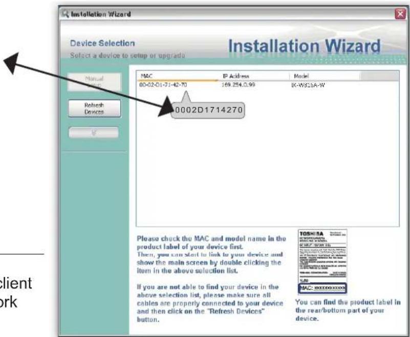

NOTE
- This Software is proprietary client software for TOSHIBA Network Camera.
Ready to Use
- Access the Network Camera on the LAN.
- Retrieve live video through a web browser.
TOSHIBA

Wireless Network Camera

natural_image
Interior view of a modern living room with white furniture, wooden flooring, and large windows (no visible text or symbols)

NOTE
- The screen image of the IK-WB16A-W may vary from the IK-WB16A.
Accessing the Network Camera
This chapter explains how to access the Network Camera through web browsers, RTSP players and 3GPP-compatible mobile devices.
Using Web Browsers
Use Installation Wizard to access the Network Cameras on the LAN.
If your network environment is not a LAN, follow these steps to access the Network Camera:
- Launch your web browser (Microsoft® Internet Explorer).
- Enter the IP address of the Network Camera in the address field. Press Enter.
- The live video will be displayed in your web browser.
- If it is the first time installing the network camera, an information bar will pop up as shown below. Follow the instructions to install the required plug-in on your computer.

NOTE
- By default, the Network Camera is not password-protected. To prevent unauthorized access, it is highly recommended to set a password for the Network Camera. For more information about how to enable password protection, please refer to Security on page 38.
▶ If you see a dialog box indicating that your security settings prohibit running ActiveX ® Controls, please enable the ActiveX ® Controls for your browser.
- Choose Tools > Internet Options > Security > Custom Level.
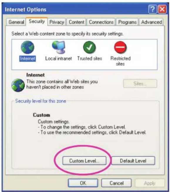
- Look for Download signed ActiveX® controls; select Enable or Prompt. Click OK.

- Refresh your web browser, then install the Active X ® control. Follow the instructions to complete installation.
Using RTSP Players
To view the MPEG-4 streaming media using RTSP players, you can use players that support RTSP streaming.
- Launch the RTSP player.
- Choose File > Open URL. A URL dialog box will pop up.
- The address format is rtsp://
: /
As most ISPs and players only allow RTSP streaming through port number 554, please set the RTSP port to 554. For more information, please refer to RTSP Streaming on page 57. For example:
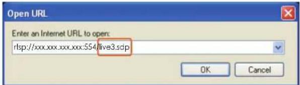
- The live video will be displayed in your player.
For more information on how to configure the RTSP access name, please refer to RTSP Streaming on page 57 for details.

natural_image
Interior view of a modern living room with wooden flooring, armchairs, and large windows (no visible text or symbols)Using 3GPP-compatible Mobile Devices
To view the streaming media through 3GPP-compatible mobile devices, make sure the Network Camera can be accessed over the Internet. For more information on how to set up the Network Camera over the Internet, please refer to Setup the Network Camera over the Internet on page 19.
To utilize this feature, please check the following settings on your Network Camera:
-
Because most players on 3GPP mobile phones do not support RTSP authentication, make sure the authentication mode of RTSP streaming is set to disable. For more information, please refer to RTSP Streaming on page 57.
-
As the bandwidth on 3G networks is limited, you will not be able to use a large video size. Please set the video and audio streaming parameters as listed below.
| Video Mode MPEG-4 | |
| Frame size 176 x 144 | |
| Maximum frame rate 5 fps | |
| Intra frame period 1S | |
| Video quality (Constant bit rate) 40kbps | |
| Audio type (GSM-AMR) 12.2kbps | |
-
As most ISPs and players only allow RTSP streaming through port number 554, please set the RTSP port to 554. For more information, please refer to RTSP Streaming on page 57.
-
Launch the player on the 3GPP-compatible mobile devices.
-
Type the following URL commands into the player.
The address format is rtsp://
For example:

Main Page
This chapter explains the layout of the main page. It is composed of the following sections: TOSHIBA Logo, Host Name, Camera Control Area, Configuration Area, Menu, and Live Video Window.

TOSHIBA Logo
Click this logo to visit the TOSHIBA website.
Host Name
The host name can be customized to fit your needs. For more information, please refer to System on page 36.
Camera Control Area
Video Stream: This Network Cmera supports multiple streams (stream 1 \~ 4) simultaneously. You can select either one for live viewing.
Digital Output: Click to turn the digital output device on or off.
PTZ Control Panel: This Network Camera supports "digital zoom" and "mechanical" pan/tilt control. Please refer to Camera Control on page 78 for detailed information.

Pan: Click this button to start the auto pan. When the current position is Home or on the left side of Home, the camera starts panning from the current position to the left-most position, then to the right-most position, and finally backward to the original position. When the current position is on the right side of Home, the camera starts panning from the current position to the right-most position, then to the left-most position, and finally backward to the original position.
Stop: Click this button to stop the Auto Pan and Auto Patrol functions.
Patrol: Once the Administrator has determined the list of preset positions, click this button to command the camera to patrol among those positions on the Patrol List. For more information, please refer to Camera control of Configuration on page 35.
Pan /Tilt speed: Adjust the speed of pan/ tilt.
| Pan speed Tilt speed | |
| -5 -5 Slower | |
| -4 -4 | |
| -3 -3 | |
| -2 -2 | |
| -1 -1 | |
| 0 | 0 |
| 1 | 1 |
| 2 | 2 |
| 3 | 3 |
| 4 | 4 |
| 5 | 5 |
Configuration Area
Client Settings: Click this button to access the client setting page. For more information, please refer to Client Settings on page 33.
Configuration: Click this button to access the configuration page of the Network Camera. It is suggested that a password be applied to the Network Camera so that only the administrator can configure the Network Camera. For more information, please refer to Configuration on page 35.
Live Video Window
■ The following window is displayed when the video mode is set to MPEG-4:

Video Title: The video title can be configured. For more information, please refer to Video Settings on page 66.
MPEG-4 Protocol and Media Options: The transmission protocol and media options for MPEG-4 video streaming. For further configuration, please refer to Client Settings on page 33.
Time: Displays the current time. For further configuration, please refer to Video Settings on page 66.
Title and Time: The video title and time can be stamped on the streaming video. For further configuration, please refer to Video Settings on page 66.
Video and Audio Control Buttons: Depending on the Network Camera model and Network Camera configuration, some buttons may not be available.

Snapshot: Click this button to capture and save still images. The captured images will be displayed pop-up window. Right-click the image and choose Save Picture As to save it in JPEG (*.jpg) or BMP.mp) format.

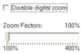
Digital Zoom: Click and uncheck "Disable digital zoom" to enable the zoom operation. The navigation been indicates the part of the image being magnified. To control the zoom level, drag the slider bar. To save to a different area you want to magnify, drag the navigation screen.
natural_image
Interior view of a modern living room with wooden flooring, framed pictures, and large windows (no visible text or symbols)
Pause: Pause the transmission of the streaming media. The button becomes the Resume button or clicking the Pause button.

Stop: Stop the transmission of the streaming media. Click the Resume button to continue omission.

Start MP4 Recording: Click this button to record video clips in MP4 file format to your computer.
ss the □ Stop MP4 Recording button to end recording. When you exit the web browser, video
ording stops accordingly. To specify the storage destination and file name, please refer to MP4 Saving
ions on page 34 for details.

Volume: When the 📋 Mute function is not activated, move the slider bar to adjust the volume on the real computer.

Mute: Turn off the volume on the local computer. The button becomes the Audio On button after king the Mute button.

Talk: Click this button to talk to people around the Network Camera. Audio will project from external speaker connected to the Network Camera. Click this button again to end talking omission.

Mic Volume: When the 🤨 Mute function is not activated, move the slider bar to adjust the orphone volume on the local computer.

Mute: Turn off the Mic volume on the local computer. The button becomes the Mic On button or clicking the Mute button.

Full Screen: Click this button to switch to full screen mode. Press the "Esc" key to switch back to normal mode.
■ The following window is displayed when the video mode is set to MJPEG:
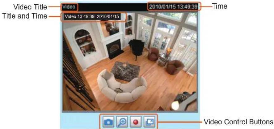
Video Title: The video title can be configured. For more information, please refer to Video Settings on page 66.
Time: Displays the current time. For more information, please refer to Video Settings on page 66.
Title and Time: Video title and time can be stamped on the streaming video. For more information, please refer to Video Settings on page 66.
Video and Audio Control Buttons: Depending on the Network Camera model and Network Camera configuration, some buttons may not be available.

Snapshot: Click this button to capture and save still images. The captured images will be displayed pop-up window. Right-click the image and choose Save Picture As to save it in JPEG (*.jpg) or BMP.mp) format.

Digital Zoom: Click and uncheck "Disable digital zoom" to enable the zoom operation. The navigation been indicates the part of the image being magnified. To control the zoom level, drag the slider bar. To ve to a different area you want to magnify, drag the navigation screen.


natural_image
Interior view of a modern living room with a sofa, coffee table, and large windows (no visible text or symbols)
Start MP4 Recording: Click this button to record video clips in MP4 file format to your computer.
ss the □ Stop MP4 Recording button to end recording. When you exit the web browser, video
ording stops accordingly. To specify the storage destination and file name, please refer to MP4 Saving
ions on page 34 for details.

Full Screen: Click this button to switch to full screen mode. Press the "Esc" key to switch back to normal mode.
Client Settings
This chapter explains how to select the stream transmission mode and saving options on the local computer. When completed with the settings on this page, click Save on the page bottom to enable the settings.
Clicking the Client Settings in Configuration Area of a Main Page, the following window is shown.
MPEG-4 Media Options
MPEG-4 Media Options
Video and Audio
Video Only
Audio Only
Select to stream video or audio data or both. This is enabled only when the video mode is set to MPEG-4.
MPEG-4 Protocol Options
MPEG-4 Protocol Options
○ UDP Unicast
UDP Multicast
TCP
HTTP
Depending on your network environment, there are four transmission modes of MPEG-4 streaming:
UDP unicast: This protocol allows for more real-time audio and video streams. However, network packets may be lost due to network burst traffic and images may be broken. Activate UDP connection when occasions require time-sensitive responses and the video quality is less important. Note that each unicast client connecting to the server takes up additional bandwidth and the Network Camera allows up to ten simultaneous accesses.
UDP multicast: This protocol allows multicast-enabled routers to forward network packets to all clients requesting streaming media. This helps to reduce the network transmission load of the Network Camera while serving multiple clients at the same time. Note that to utilize this feature, the Network Camera must be configured to enable multicast streaming at the same time. For more information, please refer to RTSP Streaming on page 57.
TCP: This protocol guarantees the complete delivery of streaming data and thus provides better video quality. The downside of this protocol is that its real-time effect is not as good as that of the UDP protocol.
HTTP: This protocol allows the same quality as TCP protocol without needing to open specific ports for streaming under some network environments. Users inside a firewall can utilize this protocol to allow streaming data through.
MP4 Saving Options
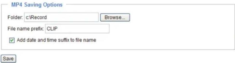
Users can record live video as they are watching it by clicking Start MP4 Recording on the main page. Here, you can specify the storage destination and file name.
Folder: Specify a storage destination for the recorded video files.
File name prefix: Enter the text that will be appended to the front of the video file name.
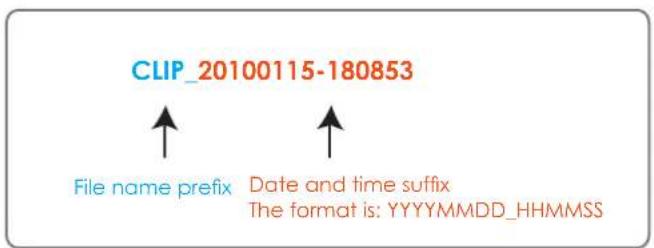
Add date and time suffix to the file name: Select this option to append the date and time to the end of the file name.
Configuration
Click Configuration on the main page to enter the camera setting pages shown below. Note that only Administrators can access the configuration page.
TOSHIBA offers an easy-to-use user interface that helps you set up your network camera with minimal effort. To simplify the setting procedure, two types of user interfaces are available: Advanced Mode for professional users and Basic Mode for entry-level users. Some advanced functions (HTTPS/ SNMP/ Access list/ Homepage layout/ Application/ Recording/ System log/ View parameters) are not displayed in Basic Mode.
If you want to set up advanced functions, please click [Advanced Mode] on the bottom of the configuration list to quickly switch to Advanced Mode.
In order to simplify the user interface, the detailed information will be hidden unless you click on the function item. When you click on the first sub-item, the detailed information for the first sub-item will be displayed; when you click on the second sub-item, the detailed information for the second sub-item will be displayed and that of the first sub-item will be hidden.
The following is the interface of the Basic Mode and the Advanced Mode:
Basic Mode
![TOSHIBA Configuration >System Home System Security Network Wireless DDNS Audio and video Motion detection Camera tampering detection Camera control Maintenance [ Advanced mode ] Version: 0100b System Host name: Wireless Network Camera Turn off the LED indicator Configuration List System Time Keep current date and time Synchronize with computer time Manual Automatic DI and DO Digital input: The active state is Low ; the current state detected is High Digital output: The active state is Grounded ; the current state detected is Open Save Click to switch to Advanced Mode Firmware Version](/content/2026/05/988175/images/58c09a31531481c96b8665d1ad034b2e6dca6d585ebe0a513b3cca30c15783f3.jpg)
Advanced Mode
![TOSHIBA Configuration >System Home System Security HTTPS SNMP Network Wireless DDNS Access list Audio and video Motion detection Camera tampering detection Camera control Homepage layout Application Recording Local storage System log View parameters Maintenance [ Basic mode ] Version: 0100b System Host name: Wireless Network Camera Turn off the LED indicator System Time Time zone: GMT-07:00 Arizona Note: You can upload your Daylight Saving Time rules on Maintenance page or use the camera default value. Keep current date and time Synchronize with computer time Manual Automatic DI and DO Digital input: The active state is Low ; the current state detected is High Digital output: The active state is Grounded ; the current state detected is Open Save Configuration List Click to switch to Basic Mode Firmware Version](/content/2026/05/988175/images/9c4f4cada6c45fa113071acc3925bd94cf1c1582e5a63a9feeedd6f698e3aca6.jpg)
Each function on the configuration list will be explained in the following sections. Those functions that are displayed only in Advanced Mode are marked with Advanced Mode. If you want to set up advanced functions, please click [Advanced Mode] on the bottom of the configuration list to quickly switch over.
System
This section explains how to configure the basic settings for the Network Camera, such as the host name and system time. It is composed of the following three columns: System, System Time and DI and DO. When finished with the settings on this page, click Save at the bottom of the page to enable the settings.
System

Host name: Enter a desired name for the Network Camera. The text will be displayed at the top of the main page.
Turn off the LED indicators: If you do not want to let others know that the network camera is in operation, you can select this option to turn off the LED indicators.
System Time

Keep current date and time: Select this option to preserve the current date and time of the Network Camera. The Network Camera's internal real-time clock maintains the date and time even when the power of the system is turned off.
Sync with computer time: Select this option to synchronize the date and time of the Network Camera with the local computer. The read-only date and time of the PC is displayed as updated.
Manual: The administrator can enter the date and time manually. Note that the date and time format are [yyyy/mm/dd] and [hh:mm:ss].
Automatic: The Network Time Protocol is a protocol which synchronizes computer clocks by periodically querying an NTP Server.
NTP server: Assign the IP address or domain name of the time-server. Leaving the text box blank connects the Network Camera to the default time servers.
Update interval: Select to update the time using the NTP server on an hourly, daily, weekly, or monthly basis.
Time zone Advanced Mode: Select the appropriate time zone from the list. If you want to upload Daylight Savings Time rules on the Maintenance page, please refer to Upload / Export Daylight Saving Time Configuration File on page 106 for details.
DI and DO

Digital input: Select High or Low to define normal status for the digital input. The Network Camera will report the current status.
Digital output: Select Grounded or Open to define normal status for the digital output. The Network Camera will show whether the trigger is activated or not.
Security
This section explains how to enable password protection and create multiple accounts.
Root Password

The administrator account name is "root", which is permanent and can not be deleted. If you want to add more accounts in the Manage User column, please apply the password for the "root" account first.
- Type the password identically in both text boxes, then click Save to enable password protection.
- A window will be prompted for authentication; type the correct user's name and password in their respective fields to access the Network Camera.
Manage Privilege
Advanced Mode

Digital Output & PTZ control: You can modify the manage privilege of operators or viewers. Check or uncheck the item, then click Save to enable the settings. If you give Viewers the privilege, Operators will also have the ability to control the Network Camera through the main page. (Please refer to Main Page on page 29.)
Allow anonymous viewing for 3GPP-compatible mobile devices: If you check this item, 3GPP clients can access the live stream without entering a User ID and Password.

NOTE
- Select RTSP Streaming Authentication to disable.
- This function will not work with Internet Explorer.
Manage User

Administrators can add up to 20 user accounts.
- Input the new user's name and password.
- Select the privilege level for the new user account. Click Add to enable the setting.
Access rights are sorted by user privilege (Administrator, Operator, and Viewer). Only administrators can access the Configuration page. Though operators cannot access the Configuration page, they can use the URL Commands to get and set the value of parameters. For more information, please refer to URL Command Guide. Viewers access only the main page for live viewing.
Here you also can change a user's access rights or delete user accounts.
- Select an existing account to modify.
- Make necessary changes and click Update or Delete to enable the setting.
HTTPS (Hypertext Transfer Protocol over SSL) Advanced Mode
This section explains how to enable authentication and encrypted communication over SSL (Secure Socket Layer). It helps protect streaming data transmission over the Internet on higher security level.
Enable HTTPS
Check this item to enable HTTPS communication, then select a connection option: "HTTP & HTTPS" or "HTTPS only". Note that you have to create and install a certificate first in the second column before clicking the Save button.

Create and Install Certificate Method
Before using HTTPS for communication with the Network Camera, a Certificate must be created first. There are three ways to create and install a certificate:
Create self-signed certificate automatically
- Select this option.
- In the first column, check Enable HTTPS secure connection, then select a connection option: "HTTP & HTTPS" or "HTTPS only".
- Click Save to generate a certificate.

- The Certificate Information will automatically be displayed in the third column as shown below. You can click Property to view detailed information about the certificate.

- Click Home to return to the main page. Change the address from "http://" to "https://" in the address bar and press Enter on your keyboard. Some Security Alert dialogs will pop up. Click OK or Yes to enable HTTPS.


Create self-signed certificate manually
- Select this option.
- Click Create to open the Create Certificate page, then click Save to generate the certificate.
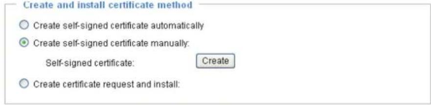
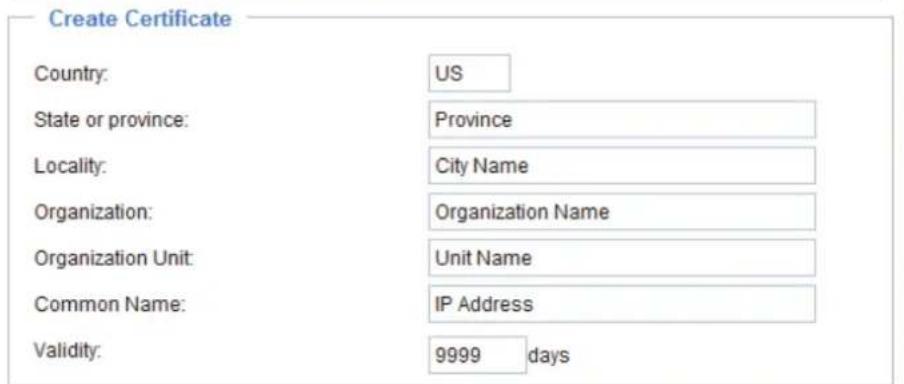


- The Certificate Information will automatically be displayed in the third column as shown below. You can click Property to see detailed information about the certificate.

Create certificate and install : Select this option if you want to create a certificate from a certificate authority.
- Select this option.
- Click Create to open the Create Certificate page, then click Save to generate the certificate.

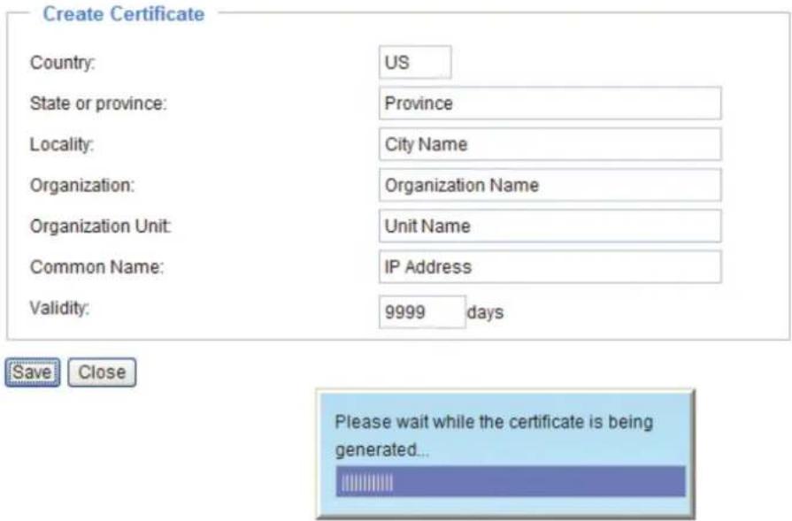
- If you see the following Information bar, click OK and click on the Information bar at the top of the page to allow pop-ups.

- The pop-up window shows an example of a certificate request.

- Look for a trusted certificate authority that issues digital certificates. Enroll the Network Camera. Wait for the certificate authority to issue a SSL certificate; click Browse... to search for the issued certificate, then click Upload in the second column.
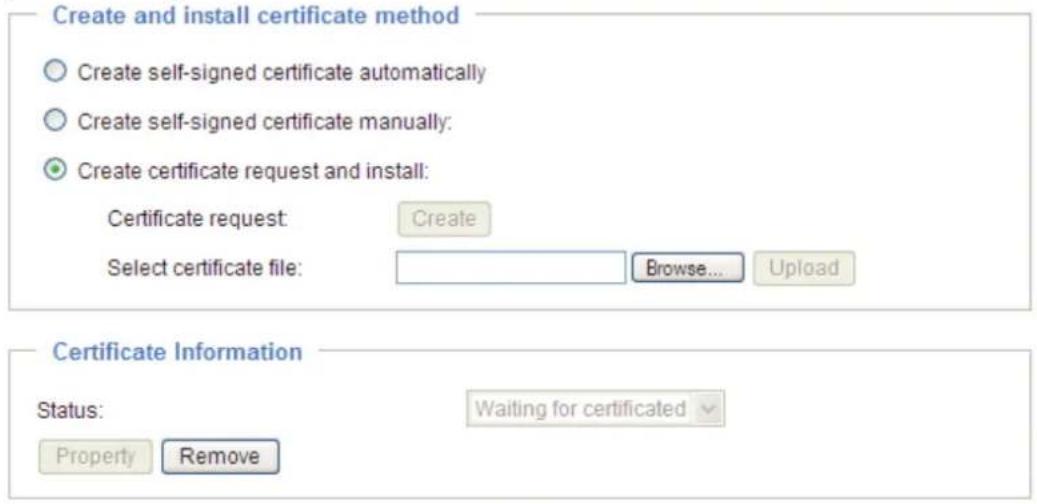

NOTE
- How do I cancel the HTTPS settings?
- Uncheck Enable HTTPS secure connection in the first column and click Save; a warning dialog will pop up.
- Click OK to disable HTTPS.

- The webpage will redirect to a non-HTTPS page automatically.
- If you want to create and install other certificates, please remove the existing one. To remove the signed certificate, uncheck Enable HTTPS secure connection in the first column and click Save. Then click Remove to erase the certificate.

SNMP (Simple Network Management Protocol) Advanced Mode
This section explains how to use the SNMP on the network camera. The Simple Network Management Protocol is an application layer protocol that facilitates the exchange of management information between network devices. It helps network administrators to remotely manage network devices and find, solve network problems with ease.
■ The SNMP consists of the following three key components:
- Manager: Network-management station (NMS), a server which executes applications that monitor and control managed devices.
- Agent: A network-management software module on a managed device which transfers the status of managed devices to the NMS.
- Managed device: A network node on a managed network. For example: routers, switches, bridges, hubs, computer hosts, printers, IP telephones, network cameras, web server, and database.
Before configuring SNMP settings on this page, please enable your NMS first.
SNMP Configuration
Enable SNMPv1, SNMPv2c
Select this option and enter the names of Read/Write community and Read Only community according to your NMS settings.
Enable SNMPv1, SNMPv2c

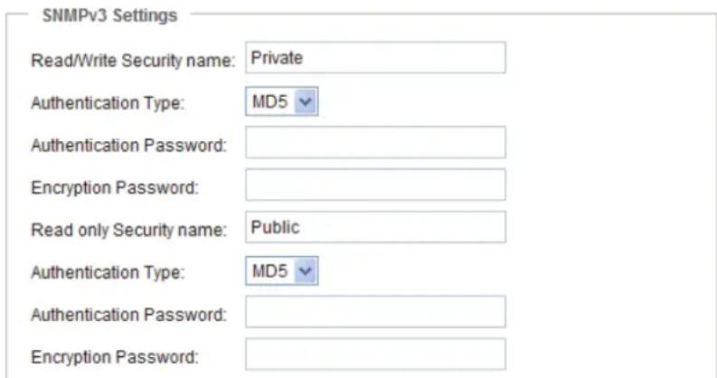
Enable SNMPv3
This option contains cryptographic security, a higher security level, which allows you to set the Authentication password and the Encryption password.
■ Security name: According to your NMS settings, choose Read/Write or Read Only and enter the community name.
■ Authentication type: Select MD5 or SHA as the authentication method.
■ Authentication password: Enter the password for authentication (at least 8 characters).
■ Encryption password: Enter a password for encryption (at least 8 characters).
Enable SNMPv3
Network
This section explains how to configure a wired network connection for the Network Camera.
Network Type
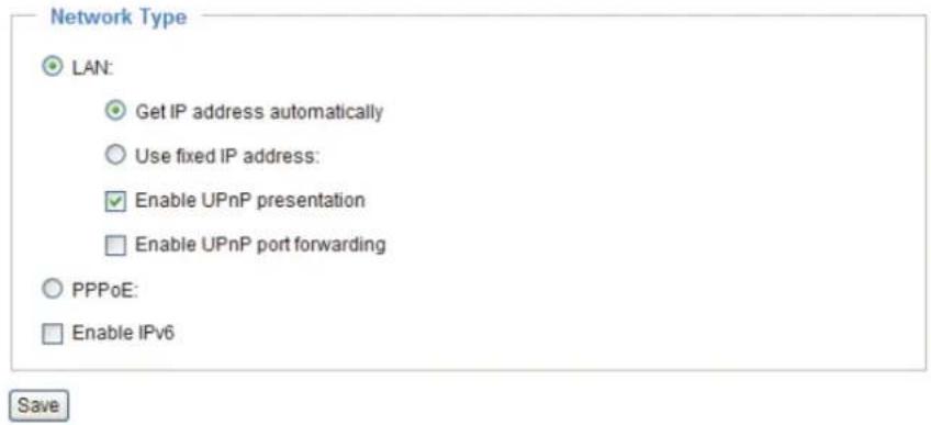
LAN
Select this option when the Network Camera is deployed on a local area network (LAN) and is intended to be accessed by local computers. The default setting for the Network Type is LAN. Remember to click Save when you complete the Network setting.
Get IP address automatically: Select this option to obtain an available dynamic IP address assigned by the DHCP server each time the camera is connected to the LAN.
Use fixed IP address: Select this option to manually assign a static IP address to the Network Camera.

Save
- You can use the TOSHIBA Installation Wizard on the software CD to easily set up the Network Camera on LAN. Please refer to Software Installation on page 23 for details.
- Enter the Static IP, Subnet mask, Default router, and Primary DNS provided by your ISP.
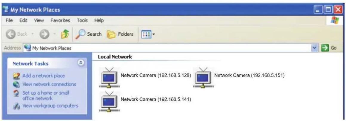
Enable UPnP presentation: Select this option to enable UPnP TM presentation for your Network Camera so that whenever a Network Camera is presented to the LAN, shortcuts of connected Network Cameras will be listed in My Network Places. You can click the shortcut to link to the web browser. Currently, UPnP TM is supported by Windows XP or later. Note that to utilize this feature, please make sure the UPnP TM component is installed on your computer.
Enable UPnP port forwarding: To access the Network Camera from the Internet, select this option to allow the Network Camera to open ports on the router automatically so that video streams can be sent out from a LAN. To utilize of this feature, make sure that your router supports UPnP TM and it is activated.
PPPoE (Point-to-point over Ethernet)
Select this option to configure your Network Camera to make it accessible from anywhere as long as there is an Internet connection. Note that to utilize this feature, it requires an account provided by your ISP.
Follow the steps below to acquire your Network Camera's public IP address.
- Set up the Network Camera on the LAN.
- Go to Home > Configuration > Application > Server Settings (please refer to Server Settings on page 90) to add a new email or FTP server.
- Go to Configuration > Application > Media Settings (please refer to Media Settings on page 93). Select System log so that you will receive the system log in TXT file format which contains the Network Camera's public IP address in your email or on the FTP server.
- Go to Configuration > Network > Network Type. Select PPPoE and enter the user name and password provided by your ISP. Click Save to enable the setting.
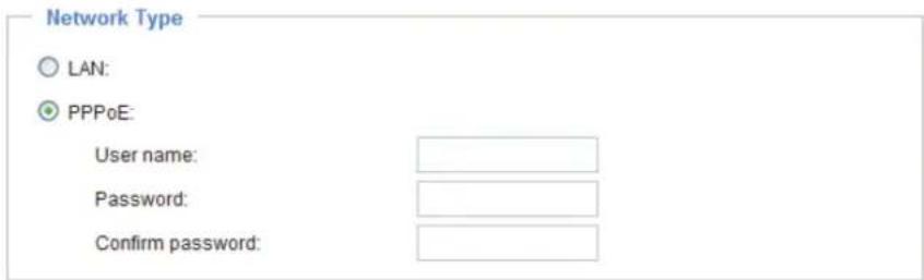
- The Network Camera will reboot.
- Disconnect the power to the Network Camera; remove it from the LAN environment.
NOTE
- If the default ports are already used by other devices connected to the same router, the Network Camera will select other ports for the Network Camera.
- If UPnP TM is not supported by your router, you will see the following message: Error: Router does not support UPnP port forwarding.
- Steps to enable the UPnP TM user interface on your computer:
Note that you must log on to the computer as a system administrator to install the UPnP TM components.
- Go to Start, click Control Panel, then click Add or Remove Programs.

- In the Add or Remove Programs dialog box, click Add/Remove Windows Components.

- In the Windows Components Wizard dialog box, select Networking Services and click Details.

- In the Networking Services dialog box, select Universal Plug and Play and click OK.

- Click Next in the following window.
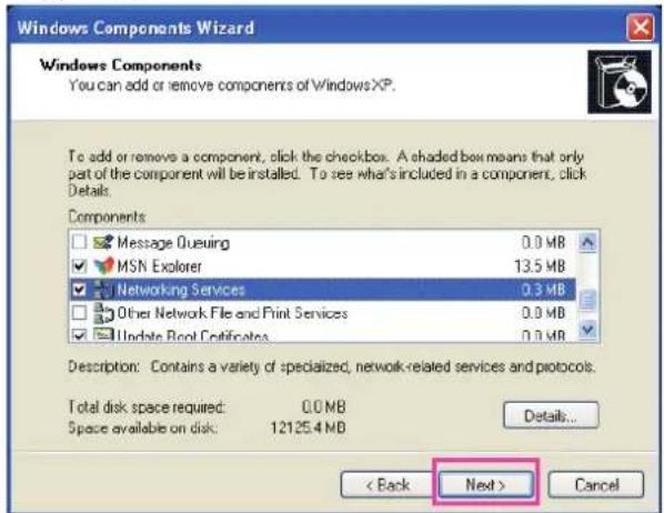
- Click Finish. UPnP TM is enabled.
- How does UPnP TM work?
UPnP TM networking technology provides automatic IP configuration and dynamic discovery of devices added to a network. Services and capabilities offered by networked devices, such as printing and file sharing, are available among each other without the need for cumbersome network configuration. In the case of Network Cameras, you will see Network Camera shortcuts under My Network Places.
- Enabling UPnP port forwarding allows the Network Camera to open a secondary HTTP port on the router-not HTTP port-meaning that you have to add the secondary HTTP port number to the Network Camera's public address in order to access the Network Camera from the Internet. For example, when the HTTP port is set to 80 and the secondary HTTP port is set to 8080, refer to the list below for the Network Camera's IP address.
| From the Internet In LAN | |
| http://203.67.124.123:8080 http://192.168.4.160 or http://192.168.4.160:8080 | |
- If the PPPoE settings are incorrectly configured or the Internet access is not working, restore the Network Camera to factory default; please refer to Restore on page 105 for details. After the Network Camera is reset to factory default, it will be accessible on the LAN.
Enable IPv6
Select this option and click Save to enable IPv6 settings.
Please note that this only works if your network environment and hardware equipment support IPv6. The browser should be Microsoft® Internet Explorer 6.5 or above.
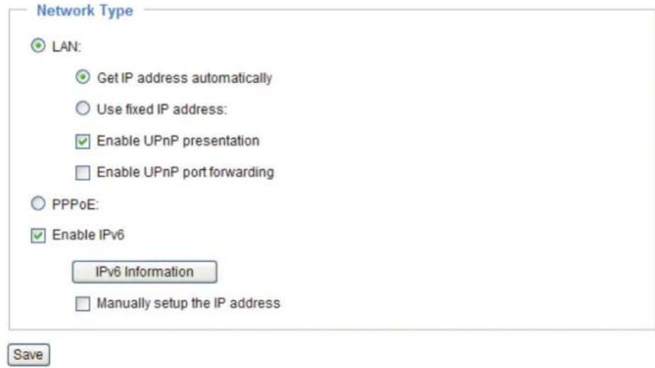
When IPv6 is enabled, by default, the network camera will listen to router advertisements and be assigned with a link-local IPv6 address accordingly.
IPv6 Information: Click this button to obtain the IPv6 information as shown below.
![IPv6 NET Information [eth0 address] IPv6 address list of host [Gateway] IPv6 address list of gateway [DNS] IPv6 address list of DNS](/content/2026/05/988175/images/ed9ecb3f30b2cd2ed03ac23333ad2db7566d9c094d141dab1cdaa5b91611c0a5.jpg)
If your IPv6 settings are successful, the IPv6 address list will be listed in the pop-up window. The IPv6 address will be displayed as follows:
Refers to Ethernet
![[eth0 address] 2001:0c08:2500:0002:0202:d1ff:fe04:65f4/64@Global fe80:0000:0000:0000:0202:d1ff:fe04:65f4/64@Link [Gateway] fe80:211:d8ff:fea2:1a2b [DNS] 2010:05c0:978d::](/content/2026/05/988175/images/a07901e1b54de22319d1cd67c4f70f1d508136aaa4add4e70f4539b135ea0a37.jpg)
Please follow the steps below to link to an IPv6 address:
- Open your web browser.
-
Enter the link-global or link-local IPv6 address in the address bar of your web browser.
-
The format should be:
![http://[2001:0c08:2500:0002:0202:d1ff:fe04:65f4]/ IPv6 address](/content/2026/05/988175/images/a3a23cd5584be23c139f31a7e3f544331fdf31d6769961e7ef044a79d16252a8.jpg)
- Press Enter on the keyboard or click Refresh button to refresh the webpage. For example:
![Network Camera - Microsoft Internet Explorer File Edit View Favorites Tools Help Back Search Favorites Address http://[2001:0c08:2500:0002:0202:d1ff:fe04:65f4]/ TOSHIBA Wii](/content/2026/05/988175/images/2923398780647f5b3a19ffcdcbdda6c9bd25fdbcf3d3a58698f86e8988d6d918.jpg)

NOTE
- If you have a Secondary HTTP port (the default value is 8080), you can also link to the webpage in the following address format: (Please refer to HTTP on page 54 for detailed information.)
![http://[2001:0c08:2500:0002:0202:d1ff:fe04:65f4]/:8080 IPv6 address Secondary HTTP port](/content/2026/05/988175/images/0c116a360401a41b45e2fdfa2a86d96ab4feb2a0bc0628fdd837466d3bd5f2e1.jpg)
- If you choose PPPoE as the Network Type, the [PPP0 address] will be displayed in the IPv6 information column as shown below. [eth0 address]
![fe80:0000:0000:0000:0202:d1ff:fe11:2299/64@Link [ppp0 address] fe80:0000:0000:0000:0202:d1ff:fe11:2299/10@Link 2001:b100:01c0:0002:0202:d1ff:fe11:2299/64@Global [Gateway] fe80::90:1a00:4142:8ced [DNS] 2001:b000::1](/content/2026/05/988175/images/61d77f2df1be1a2220d503ea31f630484237faf0e462075d8b8908c9ca2fcb28.jpg)
Manually setup the IP address: Select this option to manually set up IPv6 settings if your network environment does not have DHCPv6 server and router advertisements-enabled routers. If you check this item, the following blanks will be displayed for you to enter the corresponding information: ☑ Enable IPv6

IEEE 802.1x Advanced Mode
This function is not able to work at the time of WLAN connection of IK-WB16A-W.
Enable this function if your network environment uses IEEE 802.1x, which is a port-based network access control. The network devices, intermediary switch/access point/hub, and RADIUS server must support and enable 802.1x settings.
The 802.1x standard is designed to enhance the security of local area networks, which provides authentication to network devices (clients) attached to a network port (wired or wireless). If all certificates between client and server are verified, a point-to-point connection will be enabled; if authentication fails, access on that port will be prohibited. 802.1x utilizes an existing protocol, the Extensible Authentication Protocol (EAP), to facilitate communication.
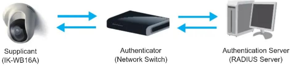
■ The components of a protected network with 802.1x authentication:
flowchart
graph LR
    A["Supplicant (IK-WB16A)"] <--> B["Authenticator (Network Switch)"]
    B <--> C["Authentication Server (RADIUS Server)"]
- Supplicant: A client end user (camera), which requests authentication.
- Authenticator (an access point or a switch): A "go between" which restricts unauthorized end users from communicating with the authentication server.
- Authentication server (usually a RADIUS server): Checks the client certificate and decides whether to accept the end user's access request.
■ The Network Camera support two types of EAP methods to perform authentication: EAP-PEAP and EAP-TLS.
Please follow the steps below to enable 802.1x settings:
- Before connecting the Network Camera to the protected network with 802.1x, please apply a digital certificate from a Certificate Authority (ie. MIS of your company) which can be validated by a RADIUS server.
- Connect the Network Camera to a PC or notebook outside of the protected LAN. Open the configuration page of the Network Camera as shown below. Select EAP-PEAP or EAP-TLS as the EAP method. In the following blanks, enter your ID and password issued by the CA, then upload related certificate(s).
IEEE 802.1x
Enable 802.1x
EAP method:
Identity:
Password:
CA certificate:
Status: no file
EAP-PEAP

IEEE 802.1x
Enable 802.1x
EAP method:
Identity:
Private key password:
CA certificate:
Status: no file
client certificate:
Status: no file
Client private key:
Status: no file
EAP-TLS


Browse...
Upload
Remove

Browse...
Upload
Remove

Browse...
Upload
Remove
- When all settings are complete, move the Network Camera to the protected LAN by connecting it to an 802.1x enabled switch. The devices will then start the authentication automatically.

NOTE
- The authentication process for 802.1x:
- The Certificate Authority (CA) provides the required signed certificates to the Network Camera (the supplicant) and the RADIUS Server (the authentication server).
- A Network Camera requests access to the protected LAN using 802.1X via a switch (the authenticator). The client offers its identity and client certificate, which is then forwarded by the switch to the RADIUS Server, which uses an algorithm to authenticate the Network Camera and returns an acceptance or rejection back to the switch.
- The switch also forwards the RADIUS Server's certificate to the Network Camera.
- Assuming all certificates are validated, the switch then changes the Network Camera's state to authorized and is allowed access to the protected network via a pre-configured port.

flowchart
graph TD
    A["Certificate Authority (CA)"] -->|1| B["TOSHIBA IK-WB16A"]
    A -->|1| C["RADIUS Server"]
    B <-->|2| D["Network Switch"]
    C <-->|3| D
    D <-->|4| C
    style A fill:#f9f,stroke:#333
    style B fill:#ccf,stroke:#333
    style C fill:#ccf,stroke:#333
    style D fill:#cfc,stroke:#333
QoS (Quality of Service) Advanced Mode
Quality of Service refers to a resource reservation control mechanism, which guarantees a certain quality to different services on the network. Quality of service guarantees are important if the network capacity is insufficient, especially for real-time streaming multimedia applications. Quality can be defined as, for instance, a maintained level of bit rate, low latency, no packet dropping, etc.
The following are the main benefits of a QoS-aware network:
■ The ability to prioritize traffic and guarantee a certain level of performance to the data flow.
■ The ability to control the amount of bandwidth each application may use, and thus provide higher reliability and stability on the network.
Requirements for QoS
To utilize QoS in a network environment, the following requirements must be met:
■ All network switches and routers in the network must include support for QoS.
■ The network video devices used in the network must be QoS-enabled.
QoS models
CoS (the VLAN 802.1p model)
IEEE802.1p defines a QoS model at OSI Layer 2 (Data Link Layer), which is called CoS, Class of Service. It adds a 3-bit value to the VLAN MAC header, which indicates prioritization from 0\~7 (Eight different classes of service are available). The priority is set up on the network switches, which then use different queuing disciplines to forward the packets.
Below is the setting column for CoS. Enter the VLAN ID of your switch (0\~4095) and choose the priority for each application (0\~7).

If you assign Video the highest level, the switch will handle video packets first.
NOTE
- The VLAN Switch (802.1p) is required. The web browsing may fail if the CoS setting is incorrect.
- Class of Service technologies do not guarantee a level of service in terms of bandwidth and delivery time; they offer a "best-effort." Users can think of CoS as "coarsely-grained" traffic control and QoS as "finely-grained" traffic control.
- Though CoS is simple to manage, it lacks scalability and does not offer end-to-end guarantees since it is based on L2 protocol.
QoS/DSCP (the DiffServ model)
DSCP-ECN defines QoS at Layer 3 (Network Layer). The Differentiated Services (DiffServ) model is based on packet marking and router queuing disciplines. The marking is done by adding a field to the IP header, called the DSCP (Differentiated Services Codepoint). This is a 6-bit field that provides 64 different class IDs. It gives an indication of how a given packet is to be forwarded, known as the Per Hop Behavior (PHB). The PHB describes a particular service level in terms of bandwidth, queueing theory, and dropping (discarding the packet) decisions. Routers at each network node classify packets according to their DSCP value and give them a particular forwarding treatment; for example, how much bandwidth to reserve for it.
Below are the setting options of DSCP (DiffServ Codepoint). Specify the DSCP value for each application (0\~63).

HTTP Advanced Mode
To utilize HTTP authentication, make sure that your have set a password for the Network Camera first; please refer to Security on page 38 for details.

Authentication: Depending on your network security requirements, the Network Camera provides two types of security settings for an HTTP transaction: basic and digest.
If basic authentication is selected, the password is sent in plain text format and there can be potential risks of being intercepted. If digest authentication is selected, user credentials are encrypted using MD5 algorithm and thus provide better protection against unauthorized accesses.
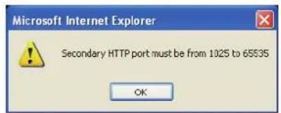
HTTP port / Secondary HTTP port: By default, the HTTP port is set to 80 and the secondary HTTP port is set to 8080. They can also be assigned to another port number between 1025 and 65535. If the ports are incorrectly assigned, the following warning messages will be displayed:

To access the Network Camera on the LAN, both the HTTP port and secondary HTTP port can be used to access the Network Camera. For example, when the HTTP port is set to 80 and the secondary HTTP port is set to 8080, refer to the list below for the Network Camera's IP address.

Access name for stream 1 \~ 5: This Network camera supports multiple streams simultaneously. The access name is used to differentiate the streaming source. Users can click Configuration > Audio and Video > Video Settings to set up the video quality of linked streams.
HTTPS

By default, the HTTPS port is set to 443. It can also be assigned to another port number between 1025 and 65535.
Two way audio

By default, the two way audio port is set to 5060. Also, it can also be assigned to another port number between 1025 and 65535.
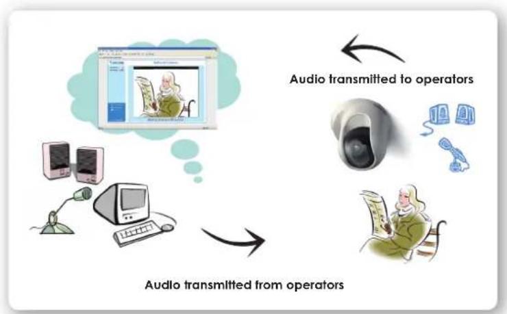
The Network Camera supports two way audio communication so that operators can transmit and receive audio simultaneously. By using the Network Camera's built-in or external microphone and an external speaker, you can communicate with people around the Network Camera.
Note that as JPEG only transmits a series of JPEG images to the client, to enable the two-way audio function, make sure the video mode is set to "MPEG-4" on the Audio and Video Settings page and the media option is set to "Video and Audio" on the Client Settings page. Please refer to Client Settings on page 33 and Audio and Video Settings on page 64.
flowchart
graph TD
    A["Computer"] -->|Audio transmitted from operators| B["Operator"]
    C["Monitor"] -->|Audio transmitted to operators| B
    D["Phone"] -->|Audio transmitted to operators| B
    E["User"] -->|Audio transmitted from operators| B

Click 📄 to enable audio transmission to the Network Camera; click 📋 to adjust the volume of microphone; click ⬇ to turn off the audio. To stop talking, click 📋 again.
FTP

The FTP server allows the user to save recorded video clips. You can utilize TOSHIBA Installation Wizard to upgrade the firmware via FTP server. By default, the FTP port is set to 21. It also can be assigned to another port number between 1025 and 65535.
RTSP Streaming
To utilize RTSP streaming authentication, make sure that you have set a password for the Network Camera first; please refer to Security on page 38 for details.
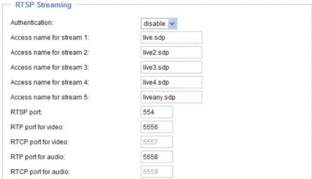
Authentication: Depending on your network security requirements, the Network Camera provides three types of security settings for streaming via RTSP protocol: disable, basic, and digest.
If basic authentication is selected, the password is sent in plain text format, but there can be potential risks of it being intercepted. If digest authentication is selected, user credentials are encrypted using MD5 algorithm, thus providing better protection against unauthorized access.
Access name for stream 1 \~ 5: This Network camera supports multiple streams simultaneously. The access name is used to differentiate the streaming source.
If you want to use an RTSP player to access the Network Camera, you have to set the video mode to MPEG-4 and use the following RTSP URL command to request transmission of the streaming data. rtsp://
For example, when the access name for stream 3 is set to live.sdp:
- Launch an RTSP player.
- Choose File > Open URL. A URL dialog box will pop up.
- Type the above URL command in the text box.
- The live video will be displayed in your player.

RTSP port /RTP port for video, audio/ RTCP port for video, audio
■ RTSP (Real-Time Streaming Protocol) controls the delivery of streaming media. By default, the port number is set to 554.
■ The RTP (Real-time Transport Protocol) is used to deliver video and audio data to the clients. By default, the RTP port for video is set to 5556 and the RTP port for audio is set to 5558.
■ The RTCP (Real-time Transport Control Protocol) allows the Network Camera to transmit the data by monitoring the Internet traffic volume. By default, the RTCP port for video is set to 5557 and the RTCP port for audio is set to 5559.
The ports can be changed to values between 1025 and 65535. The RTP port must be an even number and the RTCP port is the RTP port number plus one, and thus is always an odd number. When the RTP port changes, the RTCP port will change accordingly.
If the RTP ports are incorrectly assigned, the following warning message will be displayed:

Multicast settings for stream 1 \~ 5: Click the items to display the detailed configuration information. Select the Always multicast option to enable multicast for stream 1 \~ 5.
![Multicast settings for stream 1: □ Always multicast Multicast group address: 239.128.1.99 Multicast video port: 5560 Multicast RTCP video port: 5561 Multicast audio port: 5562 Multicast RTCP audio port: 5563 Multicast TTL [1~255]: 15 Multicast settings for stream 2: □ Always multicast Multicast group address: 239.128.1.100 Multicast video port: 5564 Multicast RTCP video port: 5565 Multicast audio port: 5566 Multicast RTCP audio port: 5567 Multicast TTL [1~255]: 15](/content/2026/05/988175/images/3ad5fa235f46c25b733b16eccc2eb0e6ce6ff71b8975aff6ea471287c9e9fac5.jpg)
Unicast video transmission delivers a stream through point-to-point transmission; multicast, on the other hand, sends a stream to the multicast group address and allows multiple clients to acquire the stream at the same time by requesting a copy from the multicast group address. Therefore, enabling multicast can effectively save Internet bandwidth.
The ports can be changed to values between 1025 and 65535. The multicast RTP port must be an even number and the multicast RTCP port number is the multicast RTP port number plus one, and thus is always odd. When the multicast RTP port changes, the multicast RTCP port will change accordingly.
If the multicast RTP video ports are incorrectly assigned, the following warning message will be displayed:

Multicast TTL [1\~255]: The multicast TTL (Time To Live) is the value that tells the router the range a packet can be forwarded.
Wireless LAN (IK-WB16A-W only)

SSID (Service Set Identifier): This is the name that identifies a wireless network. Access Points and wireless clients attempting to connect to a specific WLAN (Wireless Local Area Network) must use the same SSID. The default setting is "default". Note: The maximum length for an SSID is 32 single-byte characters and cannot consist of ", <, >, or blank spaces.
Wireless mode: Click on the pull-down menu to select from the following options:
■ Infrastructure: Connect the Network Camera to the WLAN via an Access Point. (default setting)
■ Ad-Hoc: Connect the Network Camera directly to a host equipped with a wireless adapter in a peer-to-peer environment.

Channel: While in infrastructure mode, the channel is selected automatically to match the channel setting of the selected Access Point. In Ad-Hoc mode, the channel must be manually set to the same channel for each wireless adapter. The default channel setting depends on the installed region.
Security: Select the data encrypt method. There are four types, including: none, WEP, WPA-PSK, and WPA2-PSK.

-
None: No data encryption.
-
WEP (Wired Equivalent Privacy): This allows communication only with other devices with identical WEP settings.

Save
■ Authentication Mode: Choose one of the following modes. The default setting is "Open".
Open – Communicates the key across the network.
Shared – Allows communication only with other devices with identical WEP settings.
■ Key length: The administrator can set the key length to 64 or 128 bits.
The default setting is "64 bits".
■ Key format: Hexadecimal or ASCII. The fault setting is "HEX".
HEX digits consist of the numbers 0\~9 and the letters A-F.
ASCII is a code for representing English letters as numbers from 0-127 except ", <, >, and the space character which are reserved.
■ Network Key: Enter a key in either hexadecimal or ASCII format.
You can select different key lengths, the acceptable input lengths are as follows:
64-bit key length: 10 Hex digits or 5 characters.
128-bit key length: 26 Hex digits or 13 characters.

NOTE
- When 22("), 3C(<), or 3E(>) are input as network keys, the key format cannot be changed to ASCII format.
- WPA-PSK: Use WPA (Wi-Fi Protected Access) pre-shared key WPA2-PSK: Use WPA2 pre-shared key.
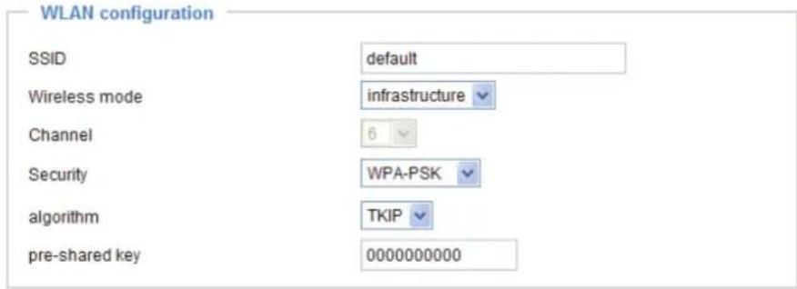
Save
Wi-Fi Protected Access (WPA and WPA2) is a certification program to indicate compliance with the security protocol created to secure wireless computer networks. This protocol improved several serious weaknesses of the previous system, WEP. WPA2 is advanced protocol, it introduces a new AES based algorithm, that is considered more secure.
■ Algorithm: Choose one of the following algorithms for WPA-PSK and WPA2-PSK modes. TKIP (Temporal Key Integrity Protocol): A security protocol used in IEEE 802.11 wireless networks. TKIP is a “wrapper” that goes around the existing WEP encryption. TKIP is comprised of the same encryption engine and RC4 algorithm defined for WEP; however, the key used for encryption in TKIP is 128 bits long. This solves the first problem of WEP: a short key length.
AES (Advanced Encryption Standard): In cryptography, the Advanced Encryption Standard (AES), also known as Rijndael, is a block cipher adopted as an encryption standard by the U.S. government. As of 2006, AES is one of the most popular algorithms used in symmetric key cryptography.
■ Pre-shared Key: Enter a key in ASCII format. The length of the key can be between 8 to 63 characters.

NOTE
- After wireless configurations are completed, click Save and the camera will reboot. Wait for the live image to be reloaded to your browser. And you have to unplug the power and Ethernet cables from the camera; then re-plug the power cable to the camera. The camera will switch to wireless mode.
- Some invalid settings may cause the system to fail to respond. Change the configuration settings only if necessary and consult with your network supervisor or experienced users for correct settings. Once the system has lost contact, please refer to Maintenance on page 105 for reset and restore procedures.
- IEEE802.11n doesn't support WEP security mode. Make sure your wireless router settings, and if the data rate is more than 54Mbps, select WPA or WPA2 security mode.
DDNS
This section explains how to configure dynamic domain name service for the Network Camera. DDNS is a service that allows your Network Camera, especially when assigned with a dynamic IP address, to have a fixed host and domain name.
DDNS: Dynamic domain name service
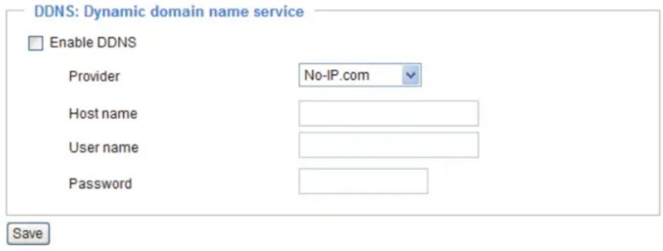
Enable DDNS: Select this option to enable the DDNS setting.
Provider: The provider list contains seven hosts that provide DDNS service. Please connect to the service provider's web site to review the service charges and sign-up for the service if you want to use DDNS.
ChangelP.com
http://www.changeip.com/toshiba/
No-IP.com
http://www.no-ip.com/ext/toshiba.php
Host Name: If the User wants to use a DDNS service, enter the camera name that is registered at the DDNS server.
User Name: The User Name field is necessary for logging into the DDNS server or to notify the User of the new IP address.
Note: When this field is input as "User Name", the following field must be input as "Password".
Password: Input the password to access the DDNS service.
Save: Click on this button to save current settings for the DDNS service.
Access List Advanced Mode
This section explains how to control access permission by verifying the client PC's IP address.
General Settings

Maximum number of concurrent streaming connection(s) limited to: Simultaneous live viewing for 1\~10 clients (including stream 1 and stream 2). The default value is 10. If you modify the value and click Save, all current connections will be disconnected and automatically attempt to re-link.
View Information: Click this button to display the connection status window showing a list of the current connections. For example:

■ IP address: Current connections to the Network Camera.
■ Elapsed time: How much time the client has been at the webpage.
■ User ID: If the administrator has set a password for the webpage, the clients have to enter a user name and password to access the live video. The user name will be displayed in the User ID column. If the administrator allows clients to link to the webpage without a user name and password, the User ID column will be empty.
There are some situations which allow clients access to the live video without a user name and password:
- The administrator does not set up a root password. For more information about how to set up a root password and manage user accounts, please refer to Security on page 38.
- The administrator has set up a root password, but set RTSP Authentication to "disable". For more information about RTSP Authentication, please refer to RTSP Streaming on page 57.
- The administrator has set up a root password, but allows anonymous viewing. For more information about Allow Anonymous Viewing, please refer to Security on page 38.
■ Refresh: Click this button to refresh all current connections.
■ Add to deny list: You can select entries from the Connection Status list and add them to the Deny List to deny access. Please note that those checked connections will only be disconnected temporarily and will automatically try to re-link again (IE Explore or Quick Time Player). If you want to enable the denied list, please check Enable access list filtering and click Save in the first column.
■ Disconnect: If you want to break off the current connections, please select them and click this button. Please note that those checked connections will only be disconnected temporarily and will automatically try to re-link again.
Enable access list filtering: Check this item and click Save if you want to enable the access list filtering function.
Filter
There are two lists for permission control: Allowed list and Denied list. Only those clients whose IP addresses are on the Allowed list and not on the Denied list can access the Network Camera. Please note that the IPv6 access list column will not be displayed unless you enable IPv6 on the Network page. For more information about IPv6 Settings, please refer to page 49 for detailed information.

■ Add a rule to Allowed/Denied list: Click Add to add a rule to Allowed/Denied list.
There are three types of rules:
Single: This rule allows the user to add an IP address to the Allowed/Denied list.
For example:

Network: This rule allows the user to assign a network address and corresponding subnet mask to the Allow/Deny List.
For example:

Range: This rule allows the user to assign a range of IP addresses to the Allow/Deny List. This rule is only applied to IPv4.
For example:

■ Delete Allowed/Denied list:
In the Delete Allowed List or Delete Denied List column, make a selection and click Delete.

NOTE
- For example, when the range of IP addresses on the allowed list is set from 1.1.1.0 to 192.255.255.255 and the range in the denied list is set from 1.1.1.0 to 170.255.255.255, only users' IPs between 171.0.0.0 and 192.255.255.255 can access the Network Camera.

Administrator IP address
Always allow the IP address to access this device: You can check this item and add the Administrator's IP address in this field to make sure the Administrator can always connect to the device.

Audio and Video
This section explains how to configure the audio and video settings of the Network Camera. It is composed of the following two columns: Video Settings and Audio Settings.
Video Settings
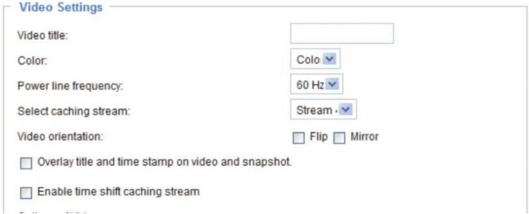
Video title: Enter a name that will be displayed on the title bar of the live video.
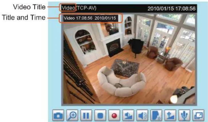
Color: Select to display color or black/white video streams.
Power line frequency: Set the power line frequency consistent with local utility settings to eliminate image flickering associated with fluorescent lights. Note that after the power line frequency is changed, you must disconnect and reconnect the power cord of the Network Camera in order for the new setting to take effect.
Select caching stream: This Network Camera supports time shift cache stream on the Network Camera. Select one stream and check the below option Enable time shift caching stream.
Video orientation: Flip--vertically reflect the display of the live video; Mirror--horizontally reflect the display of the live video. Select both options if the Network Camera is installed upside-down (ex. on the ceiling) to correct the image orientation.
Overlay title and time stamp on video: Select this option to place the video title and time on the video streams. The time refers to System Time on page 33.
Note that when the frame size is set to 176 x 144 as shown in the picture below, only the time will be stamped on the video streams.
Enable time shift caching stream Advanced Mode: Check this item to enable the time shift cache stream on the Network Camera, which will store video in the camera's embedded memory for a period of time depending on the cache memory of each Network Camera.

Options of Video Advanced Mode
There are three options for you to choose: Video Quality first, Video frame rate first, and Cropping mode. Select either one mode according to your needs.
Options of Video
Video quality first (MAX 15fps)
○ Video frame rate first (Maximum frame size 800x600)
○ Cropping mode
■ Video quality first: Select quality first will reduce the maximum frame rate to 15fps and clear the settings of motion and preset-position.
■ Video frame rate first: Select frame rate first will reduce the frame size to 800x600 and clear the settings of motion and preset-position.
■ Cropping mode: Select cropping mode will clear the settings of motion and preset-position. The cropping function allows users to crop unnecessary information and simply transmit the image of the target region for viewing or storage. With the trimming, the transmitting data size and thus, the network load is reduced and a higher frame rate is obtained. As a result, bandwidth resources and storage space can be used more efficiently.

NOTE
- In cropping mode, the maximum frame rate will be up to 30fps if the width is under 1280 and the height is under 720; otherwise, the maximum frame rate may be reduced to 15fps.
Image Settings Advanced Mode
Click Image settings to open the Image Settings page. On this page, you can tune the White balance, Brightness, Saturation, Contrast, and Sharpness settings for the video.
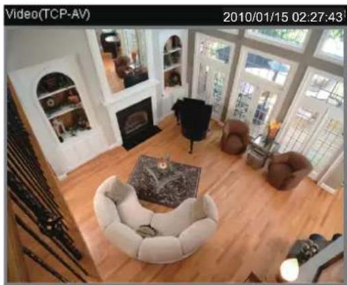
natural_image
Interior view of a modern living room with wooden flooring, featuring white furniture and large windows (no visible text or symbols)
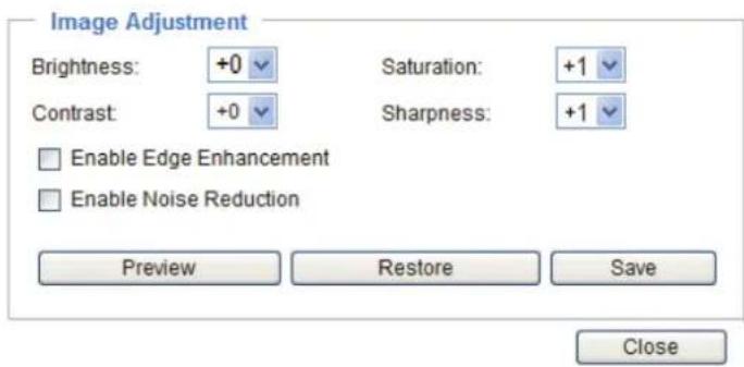
White balance: Adjust the value for the best color temperature.
■ Auto
The Network Camera automatically adjusts the color temperature of the light in response to different light sources. The white balance setting defaults to Auto and works well in most situations.
- Keep current value
Follow the steps below to manually set the white balance to compensate for the ambient lighting conditions.
- Set the White balance to Auto and click Save.
- Place a sheet of white paper in front of the lens, then allow the Network Camera to adjust the color temperature automatically.
- Select Keep Current Value to confirm the setting while the white balance is being measured.
- Click Save to enable the new setting.
Image Adjustment
■ Brightness: Adjust the image brightness level, which ranges from -4 to +4. The default value is set to 0.
■ Saturation: Adjust the image saturation level, which ranges from -5 to +5. The default value is set to +1.
■ Contrast: Adjust the image contrast level, which ranges from -5 to +5. The default value is set to 0.
■ Sharpness: Adjust the image sharpness level, which ranges from -5 to +5. The default value is set to +1.
Enable Edge Enhancement
Edge enhancement is an image processing filter that enhances the edge contrast of an image or video to improve its sharpness. Enter a value from 1 to 128 to set the degree of enhancement desired.

Enable Edge Enhancement
Strength:
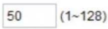
Enable Noise Reduction
Noise reduction is the process of removing noise from a signal. Select the type of noise to remove and enter a value from 1 to 63 to set the degree of enhancement required.

Enable Noise Reduction
Remove Noise:

Strength:
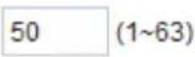
You can click Preview to fine-tune the image, or click Restore to recall the original settings without incorporating the changes. When completed with the settings on this page, click Save to enable the setting and click Close to exit the page.
Sensor Settings Advanced Mode
Click Sensor Settings to open the Image Sensor Settings page. On this page, you can set the maximum exposure time, exposure level, and AGC (Auto Gain Control) settings.
You can configure two sets of sensor settings: one for normal situations, the other for special situations, such as day/night/schedule mode.

natural_image
Interior view of a modern living room with wooden flooring, fire extinguisher, and large windows (no visible text or symbols)

Exposure
■ Maximum Exposure Time: Select a proper maximum exposure time according to the light source of the surroundings. The exposure times are selectable for the following durations: 1/120 second, 1/90 second, 1/30 second, 1/15 second, and 1/5 second. Shorter exposure times result in less light.
■ Exposure level: You can manually set the Exposure level, which ranges from 1 to 8 (dark to bright). The default value is -1.
■ Max gain: You can manually set the AGC level (2X 4X, or 8X). The default value is 4X.
■ Enable BLC (Back Light Compensation): Enable this option when the object is too dark or too bright to recognize. It allows the camera to adjust to the best light conditions in any environment and automatically give the necessary light compensation.
You can click Preview to fine-tune the image, or click Restore to recall the original settings without incorporating the changes. When completed with the settings on this page, click Save to enable the settings and click Close to exit the page.
Cropping Setting Advanced Mode
Click Cropping Setting to open the Cropping Settings page.
Please follow the steps below to set up cropping mode for multiple streams:
- Click Cropping Setting to open the window as shown below.
- Select a Captured area from the drop-down list. The floating frame, the same as the one in the Global View window on the home page, will resize accordingly. If you want to set up a customized viewing region, you can also resize and drag the floating frame to a desired position with your mouse.
Cropping setting
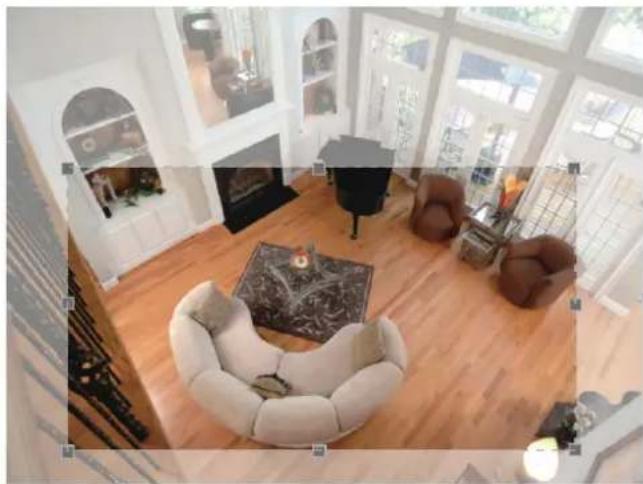
natural_image
Interior view of a modern living room with white furniture, wooden flooring, and large windows (no visible text or symbols)Captured area :
(144,216) 1280x720 custom
Save
Close
- Click Save to enable the settings and click Close to exit the window. Below is the illustration of cropped image:
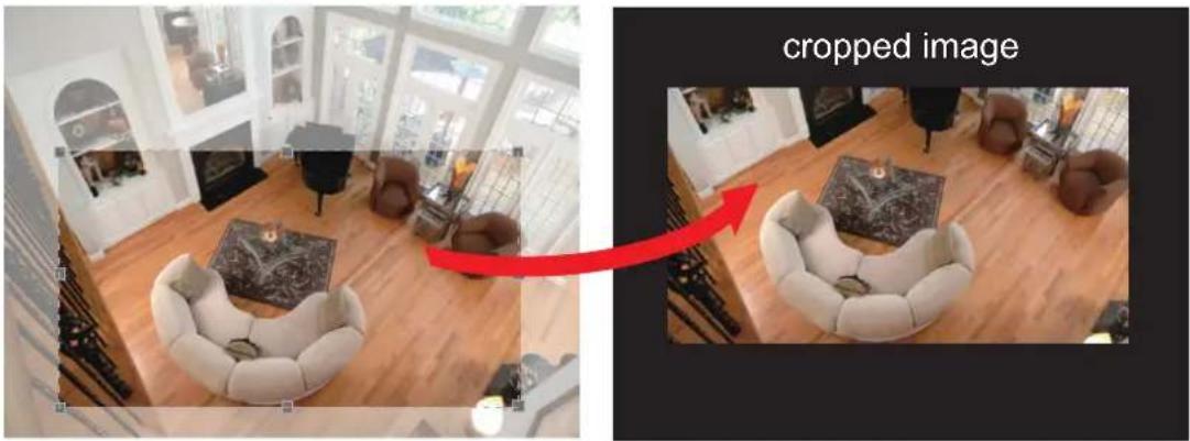
natural_image
Interior view of a modern living room with white furniture and wooden flooring, showing a red arrow pointing to a cropped image (no text or symbols on the image itself)Video quality settings for stream 1 \~ 4 Advanced Mode Click the items to display the detailed video quality settings.


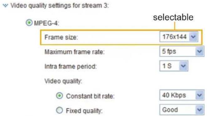

This Network Camera offers two choices of video compression standards (MPEG-4 and JPEG) for real-time viewing.
If MPEG-4 mode is selected, the video is streamed via RTSP protocol. There are four parameters provided in MPEG-4 mode which allow you to adjust the video performance:
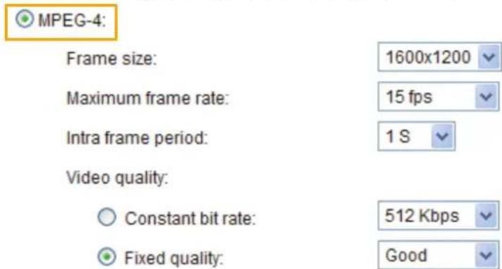
■ Frame size
You can set up different video resolution for different viewing devices. For example, set a smaller frame size and lower bit rate for remote viewing on mobile phones and a larger video size and a higher bit rate for live viewing on web browsers. Note that a larger frame size takes up more bandwidth.
■ Maximum frame rate
This limits the maximum refresh frame rate per second. Set the frame rate higher for smoother video quality.
If the power line frequency is set to 50Hz, the frame rates are selectable at 1fps, 2fps, 3fps, 5fps, 8fps, 10fps, 15fps, 20fps, and 25fps. If the power line frequency is set to 60Hz, the frame rates are selectable at 1fps, 2fps, 3fps, 5fps, 8fps, 10fps, 15fps, 20fps, 25fps, and 30fps. You can also select Customize and manually enter a value. The frame rate will decrease if you select a higher resolution.
■ Intra frame period
Determine how often to plant an I frame. The shorter the duration, the more likely you will get better video quality, but at the cost of higher network bandwidth consumption. Select the intra frame period from the following durations: 1/4 second, 1/2 second, 1 second, 2 seconds, 3 seconds, and 4 seconds.
■ Video quality
A complex scene generally produces a larger file size, meaning that higher bandwidth will be needed for data transmission. Therefore, if Constant bit rate is selected, the bandwidth utilization is fixed at a selected level, resulting in mutable video quality performance. The bit rates are selectable at the following rates: 20Kbps, 30Kbps, 40Kbps, 50Kbps, 64Kbps, 128Kbps, 256Kbps, 512Kbps, 768Kbps, 1Mbps, 2Mbps, 3Mbps, and 4Mbps. You can also select Customize and manually enter a value.
On the other hand, if Fixed quality is selected, all frames are transmitted with the same quality; bandwidth utilization is therefore unpredictable. The video quality can be adjusted to the following settings: Acceptable, Satisfactory, Good, Very Good, and Excellent. You can also select Customize and manually enter a value from 1 (high quality) to 31 (low quality).
If JPEG mode is selected, the Network Camera continuously sends JPEG images to the client, producing a moving effect similar to a filmstrip. Every single JPEG image transmitted guarantees the same image quality, which in turn comes at the expense of variable bandwidth usage. Because the media contents are a combination of JPEG images, no audio data is transmitted to the client. There are three parameters provided in MJPEG mode to control the video performance:

Frame size:
Maximum frame rate:
Video quality:
1600x1200
15 fps
Good
■ Frame size
You can set up different video resolution for different viewing devices. For example, set a smaller frame size and lower bit rate for remote viewing on mobile phones and a larger video size and a higher bit rate for live viewing on web browsers. Note that a larger frame size takes up more bandwidth.
■ Maximum frame rate
This limits the maximum refresh frame rate per second. Set the frame rate higher for smoother video quality.
If the power line frequency is set to 50Hz, the frame rates are selectable at 1fps, 2fps, 3fps, 5fps, 8fps, 10fps, 15fps, 20fps, and 25fps. If the power line frequency is set to 60Hz, the frame rates are selectable at 1fps, 2fps, 3fps, 5fps, 8fps, 10fps, 15fps, 20fps, 25fps, and 30fps. You can also select Customize and manually enter a value. The frame rate will decrease if you select a higher resolution.
■ Video quality
The video quality can be adjusted to the following settings: Acceptable, Satisfactory, Good, Very Good, and Excellent. You can also select Customize and manually enter a value from 10 (high quality) to 200 (low quality).

NOTE
- Video quality and fixed quality refers to the compression rate, so a lower value will produce higher quality.
Audio Settings

Mute: Select this option to disable audio transmission from the Network Camera to all clients. Note that if mute mode is turned on, no audio data will be transmitted even if audio transmission is enabled on the Client Settings page. In that case, the following message is displayed:

Internal microphone input gain: Select the gain of the internal audio input according to ambient conditions. Adjust the gain from +21 db (most sensitive) \~ -33 db (least sensitive).
External microphone input: Select the gain of the external audio input according to ambient conditions. Adjust the gain from +21 db (most sensitive) or -33 db (least sensitive).
Audio type: Select audio codec AAC or GSM-AMR and the bit rate Advanced Mode
■ AAC provides good sound quality at the cost of higher bandwidth consumption. The bit rates are selectable from: 16Kbps, 32Kbps, 48Kbps, 64Kbps, 96Kbps, and 128Kbps.
■ GSM-ARM is designed to optimize speech quality and requires less bandwidth. The bit rates are selectable from: 4.75Kbps, 5.15Kbps, 5.90Kbps, 6.7Kbps, 7.4Kbps, 7.95Kbps, 10.2Kbps, and 12.2Kbps.
When completed with the settings on this page, click Save to enable the settings.
NOTE
- The Network Camera offers two inputs to capture audio - internal microphone or external microphone. When external microphone is connected, it switches from internal microphone to external microphone automatically.
- The jack of microphone can use only the type of 3.5mm Stereo.
- The usable microphone is the Plug-in-power Condenser Microphones with 3.5mm Stereo mini-plug. And right angle plug is highly recommended.
Motion Detection
This section explains how to configure the Network Camera to enable motion detection. A total of three motion detection windows can be configured.

Enable motion detection

Follow the steps below to enable motion detection:
- Click New to add a new motion detection window.
- In the Window Name text box, enter a name for the motion detection window.
- To move and resize the window, drag and drop your mouse on the window.
- To delete window, click X on the top right corner of the window.
- Define the sensitivity to moving objects and the space ratio of all alerted pixels by moving the Sensitivity and Percentage slider bar.
- Click Save to enable the settings.
- Select Enable motion detection to enable this function.
For example:

Enable motion detection
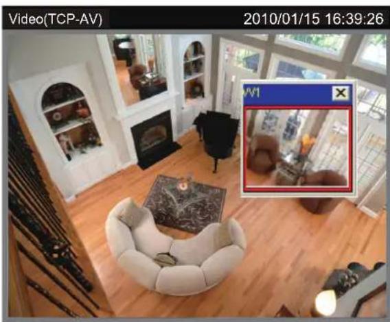
natural_image
Interior view of a modern living room with wooden flooring, featuring a sofa, fireplace, and wall-mounted furniture (no visible text or symbols)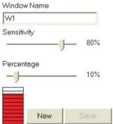
bar
| Category | Value | |---|---| | Window Name | W1 | | Sensitivity | 80% | | Percentage | 10% | | New | Save |The Percentage Indicator will rise or fall depending on the variation between sequential images. When motions are detected by the Network Camera and are judged to exceed the defined threshold, the red bar rises. Meanwhile, the motion detection window will be outlined in red. Photos or videos can be captured instantly and configured to be sent to a remote server (Email, FTP) by utilizing this feature as a trigger source. For more information on how to set an event, please refer to Application on page 84.
A green bar indicates that even though motions have been detected, the event has not been triggered because the image variations still fall under the defined threshold.


NOTE
• How does motion detection work?
A
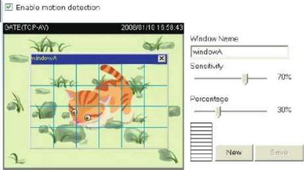
C

natural_image
Illustration of a cat and a gray cat walking together on a grid background (no text or symbols)B

D

natural_image
Illustration of a cat with fish and aquatic plants on a grid background (no text or symbols)There are two motion detection parameters: Sensitivity and Percentage. In the illustration above, frame A and frame B are two sequential images. Pixel differences between the two frames are detected and highlighted in gray (frame C) and will be compared with the sensitivity setting. Sensitivity is a value that expresses the sensitivity to moving objects. Higher sensitivity settings are expected to detect slight movements while smaller sensitivity settings will neglect them. When the sensitivity is set to 70%, the Network Camera defines the pixels in the purple areas as “alerted pixels” (frame D).
Percentage is a value that expresses the proportion of “alerted pixels” to all pixels in the motion detection window. In this case, 50% of pixels are identified as “alerted pixels”. When the percentage is set to 30%, the motions are judged to exceed the defined threshold; therefore, the motion window will be outlined in red.
For applications that require a high level of security management, it is suggested to use higher sensitivity settings and smaller percentage values.
Camera Tampering Detection
This section explains how to set up camera tamper detection. With tamper detection, the camera is capable of detecting incidents such as redirection, blocking or defocusing, or even spray paint.
![Camera tampering detection ✓ Enable camera tampering detection Trigger duration: 10 seconds [10~600] Save](/content/2026/05/988175/images/26ead3790b2786038b6a47dbe00f4552b310723f652836eac0752376e0a8a956.jpg)
Please follow the steps below to set up the camera tamper detection function:
- Check Enable camera tampering detection.
- Enter the tamper trigger duration. (10 sec. \~ 10 min.) The tamper alarm will be triggered only when the tampering factor (the difference between current frame and pre-saved background) exceeds the trigger threshold.
- Set up the event source as Camera Tampering Detection on Application page > Event Settings / Server Settings (how to send alarm message) / Media Settings (send what type of alarm message). Please refer to page 84 for detailed information.
Camera Control
This section explains how to control the Network Camera's Pan/Tilt/digitl Zoom operation via the control panel and how to preset positions.
Preset Positions
You can preset positions for the Network Camera to go to directly or patrol. A total of 20 preset positions can be configured.
Please follow the steps below to preset a position:
- Adjust the shooting area to the desired position using the buttons on the right side of the window.
- Click Set as home or Default home to define your home position.
- Enter a name for the preset position, which allows for up to forty characters. Click Add to enable the settings. The preset positions will be displayed under the Preset Location list on the left-hand side.
- To add additional preset positions, please repeat steps 1\~2.
- To remove a preset position from the list, select it from the drop-down list and click Delete.
- The preset positions will also displayed on the main page. Please refer to the illustration on the next page.
- Click Save to enable the settings.
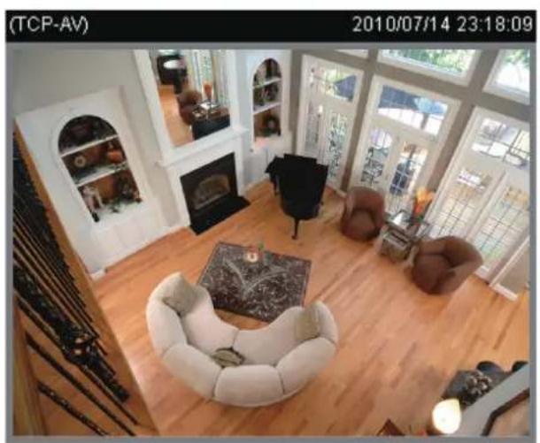
natural_image
Interior view of a modern living room with wooden flooring, fire planter, and large windows (no visible text or symbols)
1 Functions are the same as the Control Panel on the home page

flowchart
graph TD
    A["Preset locations"] --> B["Source"]
    A --> C["Dwelling time"]
    D["Select"] --> E["Remove"]
    D --> F["Up"]
    D --> G["Down"]
    H["Update"] --> I["End"]
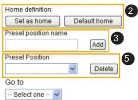
Home page in PTZ Mode
TOSHIBA

Wireless Network Camera
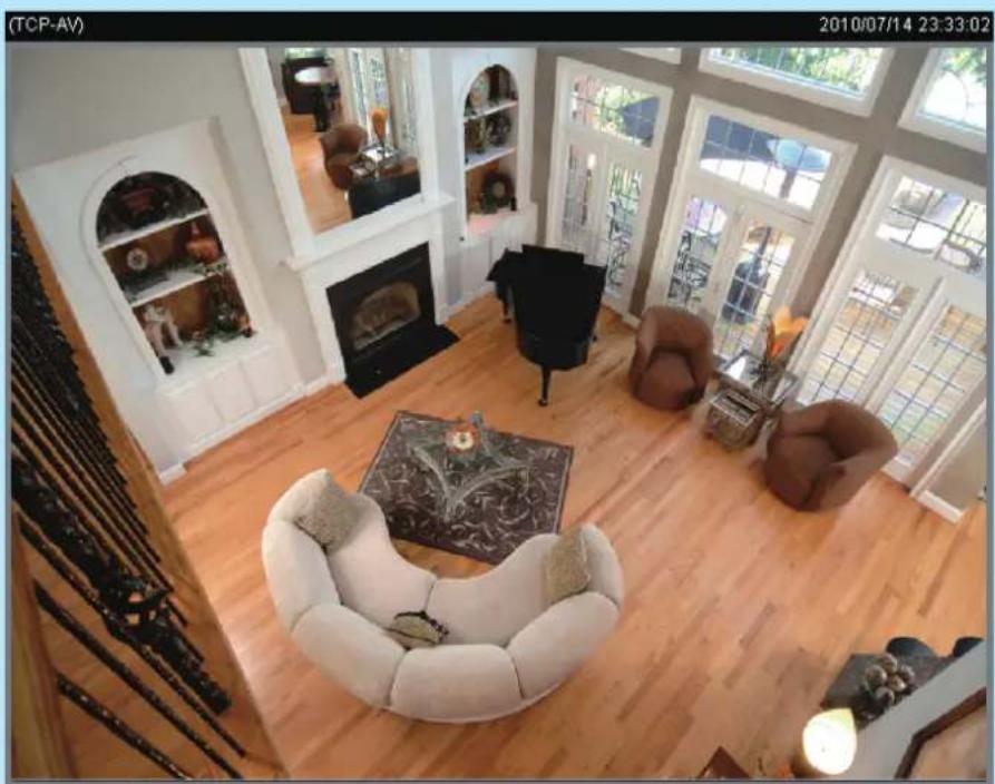
natural_image
Interior view of a modern living room with wooden flooring, featuring a sofa, armchairs, and large windows (no visible text or symbols)
■ The Preset Positions will also be displayed on the home page. Select one from the drop-down list, and the Network Camera will move to the selected preset position.
Patrol Settings
You can select some preset positions for the Network Camera to patrol.
Please follow the steps below to set up a patrol schedule:
- Click a preset location on the list and click Select.
- The selected preset location will be displayed on the Source list.
- Set the Dwelling time for the preset location during auto patrol. You can also manually enter a value in the blank and click Update.
- Repeat step 1 and 3 to select additional preset locations.
- If you want to delete a selected location, select it from the Source list and click Remove.
- Select a location and click Up or Down to rearrange the patrol order.
- Adjust the Auto pan/patrol speed. 1(slow) \~5(fast)
- Click Save to enable the settings.

natural_image
Interior view of a modern living room with wooden flooring, armchairs, and large windows (no visible text or symbols)
Patrol settings
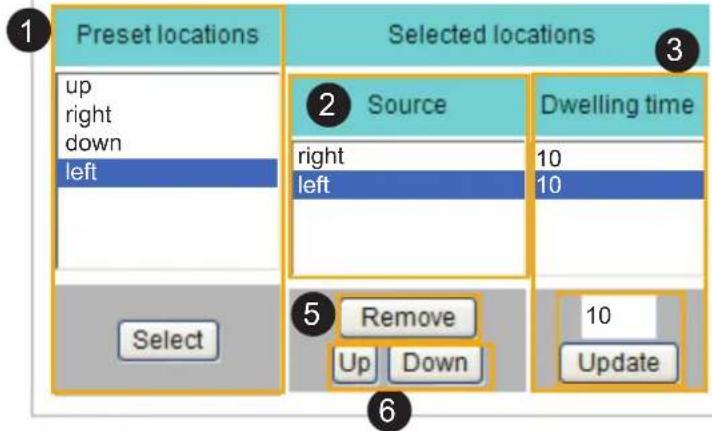
Save
8
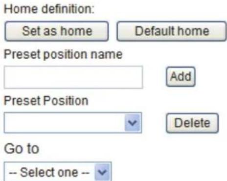
Homepage Layout Advanced Mode
This section explains how to set up your own customized homepage layout.
Preview
This column shows the settings of your homage layout. You can manually select the background and font colors in Theme Options (the third column on this page). The settings will be displayed automatically in this Preview field. The following shows the homepage using the default settings:

Logo
Here you can change the logo at the top of your homepage.

Follow the steps below to upload a new logo:
- Click Custom and the Browse field will appear.
- Select a logo from your files.
- Click Upload to replace the existing logo with a new one.
- Enter a website link if necessary.
- Click Save to enable the settings.
Theme Options
Here you can change the color of your homepage layout. There are three types of preset patterns for you to choose from. The new layout will simultaneously appear in the Preview filed. Click Save to enable the settings.

Save

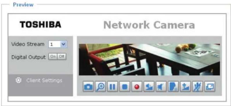

■ Follow the steps below to set up the customed homepage:
- Click Custom on the left column.
- Click the field where you want to change the color on the right column.

- The palette window will pop up as shown below.


- Drag the slider bar and click on the left square to select a desired color.
- The selected color will be displayed in the corresponding fields and in the Preview column.
- Click Save to enable the settings.
Application Advanced Mode
This section explains how to configure the Network Camera to responds to particular situations (event). A typical application is that when a motion is detected, the Network Camera sends buffered images to an FTP server or e-mail address as notifications.
In the illustration on the right, an event can be triggered by many sources, such as motion detection or external digital input devices. When an event is triggered, you can specify what type of action that will be performed. You can configure the Network Camera to send snapshots or videos to your email address or FTP site.

flowchart
graph TD
    A["Event Trigger"] --> B["Action"]
    B --> C["Media (what to send)"]
    B --> D["Server (where to send)"]
    C --> E["ex. Snapshot, Video Clips, System Log, Digital Output"]
    D --> F["ex. Email, FTP, HTTP Server, Network Storage"]
    style A fill:#f9f,stroke:#333
    style B fill:#ccf,stroke:#333
    style C fill:#cfc,stroke:#333
    style D fill:#fcc,stroke:#333

Event Settings
In the Event Settings column, click Add to open the Event Settings page. On this page, you can arrange three elements -- Trigger, Schedule, and Action to set an event. A total of 3 event settings can be configured.
Event name:
Enable this event
Priority: Normal
Detect next event after 10 second(s).
Note: This can only applied to motion detection and digital input
Trigger
Video motion detection:
Periodically:
Digital input
System boot
Recording notify
○ Camera tampering detection:
Event Schedule
Sun Mon Tue Wed Thu Fri Sat
Time
Always
From 00:00 to 24:00 [hh:mm]
Action
☐ Trigger digital output for 1 seconds
Move to preset location:
Note: Please configure Preset locations first
Add Server [ Add Media
Server
Media
SD
---None---
SD Test
View
Event name: Enter a name for the event setting.
Enable this event: Select this option to enable the event setting.
Priority: Select the relative importance of this event (High, Normal, or Low). Events with a higher priority setting will be executed first.
Detect next event after □ seconds: Enter the duration in seconds to pause motion detection after a motion is detected.
An event is an action initiated by a user-defined trigger source; it is the causal arrangement of the following three elements: Trigger, Event Schedule, and Action.
Trigger
This is the cause or stimulus which defines when to trigger the Network Camera. The trigger source can be configured to use the Network Camera's built-in motion detection mechanism or external digital input devices.
There are several choices of trigger sources as shown below. Select the item to display the detailed configuration options.
■ Video motion detection
This option makes use of the built-in motion detection mechanism as a trigger source. To enable this function, you need to configure a Motion Detection Window first. For more information, please refer to Motion Detection on page 75 for details.

■ Periodically
This option allows the Network Camera to trigger periodically for every other defined minute. Up to 999 minutes are allowed.

■ Digital input
This option allows the Network Camera to use an external digital input device or sensor as a trigger source. Depending on your application, there are many choices of digital input devices on the market which helps to detect changes in temperature, vibration, sound, and light, etc.
■ System boot
This option triggers the Network Camera when the power to the Network Camera is disconnected.
■ Camera tampering detection
This option allows the Network Camera to trigger when the camera detects that is being tampered with. To enable this function, you need to configure the Tampering Detection option first. Please refer to page 77 for detailed information.
Trigger
Video motion detection:
Periodically:
Digital input
System boot
Recording notify
Camera tampering detection:
Note: Please configure Camera tampering detection first
Event Schedule
Specify the period for the event.
Event Schedule
Sun Mon Tue Wed Thu Fri Sat
Time
Always
From 00:00 to 24:00 [hh:mm]
■ Select the days of the week.
■ Select the recording schedule in 24-hr time format.
Action
Define the actions to be performed by the Network Camera when a trigger is activated.

■ Trigger digital output for □ seconds
Select this option to turn on the external digital output device when a trigger is activated. Specify the length of the trigger interval in the text box.
■ Move to preset location
Select this option, the Network Camera will move to the preset location when a trigger is activated. Please setup the preset locations first. Please refer to Preset Positions on page 78 for detailed information.
To set an event with recorded video or snapshots, it is necessary to configure the server and media settings so that the Network Camera will know what action to take (such as which server to send the media files to) when a trigger is activated.
■ Add Server / Add Media
Click Add Server to configure Server Settings. For more information, please refer to Server Settings on page 90.
Click Add Media to configure Media Settings. For more information, please refer to Media Settings on page 93.
Here is an example of the Event Settings page:
Event name: Event1
Enable this event
Priority: Normal
Detect next event after 10 second(s).
Note: This can only applied to motion detection and digital input
Trigger
Video motion detection
Periodically
Digital input
System boot
Recording notify
○ Camera tampering detection
Event Schedule
Sun Mon Tue Wed Thu Fri Sat
Time
Always
From 00:00 To 24:00 [hh:mm]
Action
Trigger digital output for 1 seconds
Move to preset location:
Note: Please configure Preset locations first
Add Server Add Media
Server
Media
Extra parameter
SD
----None---- ▼ SD Test View
FTP
----None----
NAS
---None---
---None---
HTTP
---None---
Save Close
When completed, click Save to enable the settings and click Close to exit Event Settings page. The new event settings / server settings / media settings will appear in the event drop-down list on the Application page.
Here is an example of the Application page with an event setting:

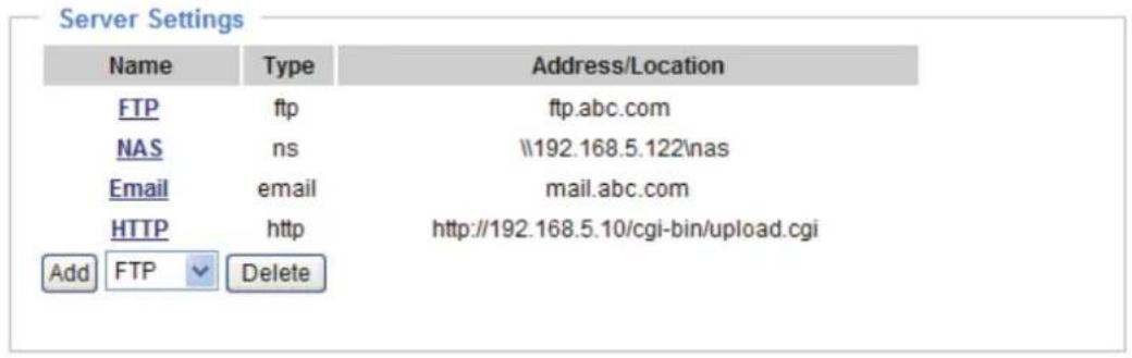
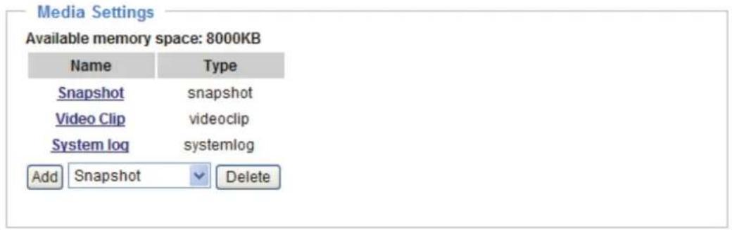

When the Event Status is ON, once an event is triggered by motion detection, the Network Camera will automatically send snapshots via e-mail.
If you want to stop the event trigger, you can click ON to turn it to OFF status or click Delete to remove the event setting.
To remove a server setting from the list, select a server name from the drop-down list and click Delete. Note that only when the server setting is not being applied to an event setting can it be deleted.
To remove a media setting from the list, select a media name from the drop-down list and click Delete. Note that only when the media setting is not being applied to an event setting can it be deleted.
Server Settings
Click Add Server on Event Settings page to open the Server Setting page. On this page, you can specify where the notification messages are sent when a trigger is activated. A total of 5 server settings can be configured.
Server name: Enter a name for the server setting.
Server Type
There are four choices of server types available: Email, FTP, HTTP, and Network storage. Select the item to display the detailed configuration options. You can configure either one or all of them.
Email: Select to send the media files via email when a trigger is activated.

■ Sender email address: Enter the email address of the sender.
■ Recipient email address: Enter the email address of the recipient.
■ Server address: Enter the domain name or IP address of the email server.
■ User name: Enter the user name of the email account if necessary.
■ Password: Enter the password of the email account if necessary.
■ Server port: The default mail server port is set to 25. You can also manually set another port.
If your SMTP server requires a secure connection (SSL), check This server requires a secure connection (SSL).
To verify if the email settings are correctly configured, click Test. The result will be shown in a pop-up window. If successful, you will also receive an email indicating the result.

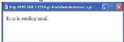
Click Save to enable the settings, then click Close to exit the page.
FTP: Select to send the media files to an FTP server when a trigger is activated.
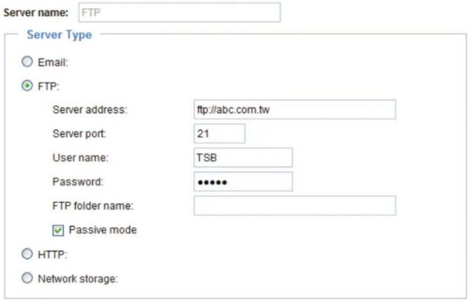
Test Save Close
■ Server address: Enter the domain name or IP address of the FTP server.
■ Server port
By default, the FTP server port is set to 21. It can also be assigned to another port number between 1025 and 65535.
■ User name: Enter the login name of the FTP account.
■ Password: Enter the password of the FTP account.
■ FTP folder name
Enter the folder where the media file will be placed. If the folder name does not exist, the Network Camera will create one on the FTP server.
■ Passive mode
Most firewalls do not accept new connections initiated from external requests. If the FTP server supports passive mode, select this option to enable passive mode FTP and allow data transmission to pass through the firewall.
To verify if the FTP settings are correctly configured, click Test. The result will be shown in a pop-up window as shown below. If successful, you will also receive a test.txt file on the FTP server.
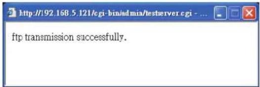

Click Save to enable the settings, then click Close to exit the page.
HTTP: Select to send the media files to an HTTP server when a trigger is activated.

■ URL: Enter the URL of the HTTP server.
■ User name: Enter the user name if necessary.
■ Password: Enter the password if necessary.
To verify if the HTTP settings are correctly configured, click Test. The result will be shown in a pop-up window as below. If successful, you will receive a test.txt file on the HTTP server.


Click Save to enable the settings, then click Close to exit the page.
Network storage: Select to send the media files to a network storage location when a trigger is activated. Please refer to Network Storage Setting on page 97 for details.
Click Save to enable the settings, then click Close to exit the page.
When completed, the new server settings will automatically be displayed on the Event Settings page. For example:

Media Settings
Click Add Media on the Event Settings page to open the Media Settings page. On this page, you can specify the type of media that will be sent when a trigger is activated. A total of 5 media settings can be configured.
Media name: Enter a name for the media setting.
Media Type
There are three choices of media types available: Snapshot, Video Clip, and System log. Select the item to display the detailed configuration options. You can configure either one or all of them.
Snapshot: Select to send snapshots when a trigger is activated.
![Media name: Snapshot Media Type Snapshot: Source: Stream1 Send 1 pre-event image(s) [0~7] Send 1 post-event image(s) [0~7] File name prefix: Snapshot_ Add date and time suffix to file name Video Clip System log Save Close](/content/2026/05/988175/images/0bccc1fe8d119dd6a1bdf4ac1c080b398ebfec80ef93656e078f7fd7c2596b83.jpg)
■ Source: Select to take snapshots from stream 1 \~ 4.
■ Send □ pre-event images
The Network Camera has a buffer area; it temporarily holds data up to a certain limit. Enter a number to decide how many images to capture before a trigger is activated. Up to 7 images can be generated.
■ Send □ post-event images
Enter a number to decide how many images to capture after a trigger is activated. Up to 7 images can be generated.
For example, if both the Send pre-event images and Send post-event images are set to 7, a total of 15 images are generated after a trigger is activated.

■ File name prefix
Enter the text that will be appended to the front of the file name.
■ Add date and time suffix to the file name
Select this option to add a date/time suffix to the file name.
For example:
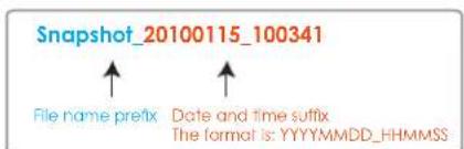
Click Save to enable the settings, then click Close to exit the page.
Video clip: Select to send video clips when a trigger is activated.
![Media Type Snapshot: Video Clip Source: Stream1 Pre-event recording: 0 seconds [0~9] Maximum duration: 5 seconds [1~10] Maximum file size: 500 Kbytes [50~800] File name prefix: Video Clip_ System log Save Close](/content/2026/05/988175/images/39a6da8cfa96943e44d646a9cfa8d100d9aa119b4ece076bc82213a59f1e1c93.jpg)
■ Source: The source of video clip, which will be identical to the time shift caching stream. For more information about time shift caching stream, please refer to page 66.
■ Pre-event recording
The Network Camera has a buffer area; it temporarily holds data up to a certain limit. Enter a number to decide the duration of recording before a trigger is activated. Up to 9 seconds can be set.
■ Maximum duration
Specify the maximum recording duration in seconds. Up to 10 seconds can be set.
For example, if pre-event recording is set to five seconds and the maximum duration is set to ten seconds, the Network Camera continues to record for another 4 seconds after a trigger is activated.

■ Maximum file size
Specify the maximum file size allowed.
■ File name prefix
Enter the text that will be appended to the front of the file name.
For example:
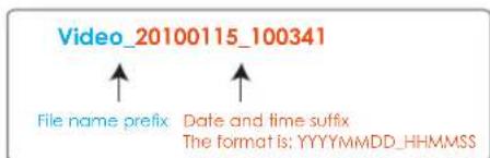
Click Save to enable the settings, then click Close to exit the page.
System log: Select to send a system log when a trigger is activated. Click Save to enable the settings, then click Close to exit the page.
When completed, click Save to enable the settings and click Close to exit this page. The new media settings will appear on the Event Settings page.
You can continue to select a server and media type for the event. Please go back to page 91 for detailed information.

■ SD Test: Click to test your SD card. The system will display a message indicating success or failure. If you want to use your SD card for local storage, please format it before use. Please refer to page 105 for detailed information.
■ Create folders by date, time, and hour automatically: If you check this item, the system will generate folders automatically by date.
■ View: Click this button to open a file list window. This function is only for SD card and Network Storage.
If you click View button of SD card, a Local storage page will pop up for you to manage recorded files on SD card. For more information about Local storage, please refer to page 100 for illustration.
If you click View button of Network storage, a file directory window will pop up for you to view recorded data on Network storage. For detailed illustration, please refer to the next page.
The following is an example of a file destination with video clips:

Click 20100115 to open the directory:
The format is: HH (24r)
Click to open the file list for that hour

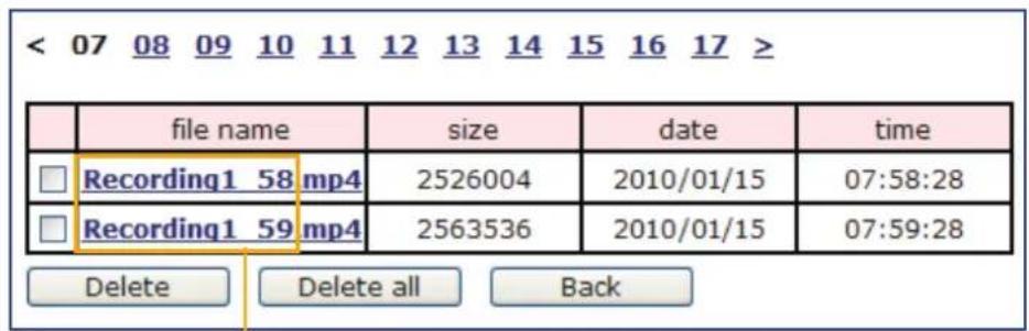
The format is: File name prefix + Minute (mm)
You can set up the file name prefix on Media Settings page.
Please refer to page 93 for detailed information.
Recording Advanced Mode
This section explains how to configure the recording settings for the Network Camera.
Recording Settings
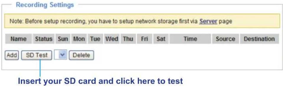

NOTE
- Before setting up this page, please set up the Network Storage on the Server Settings page first.
- Please remember to format your SD card when using for the first time. Please refer to page 100 for detailed information.
Network Storage Setting
Click Server to open the Server Settings page and follow the steps below to set up:
- Fill in the information for your server.
For example:
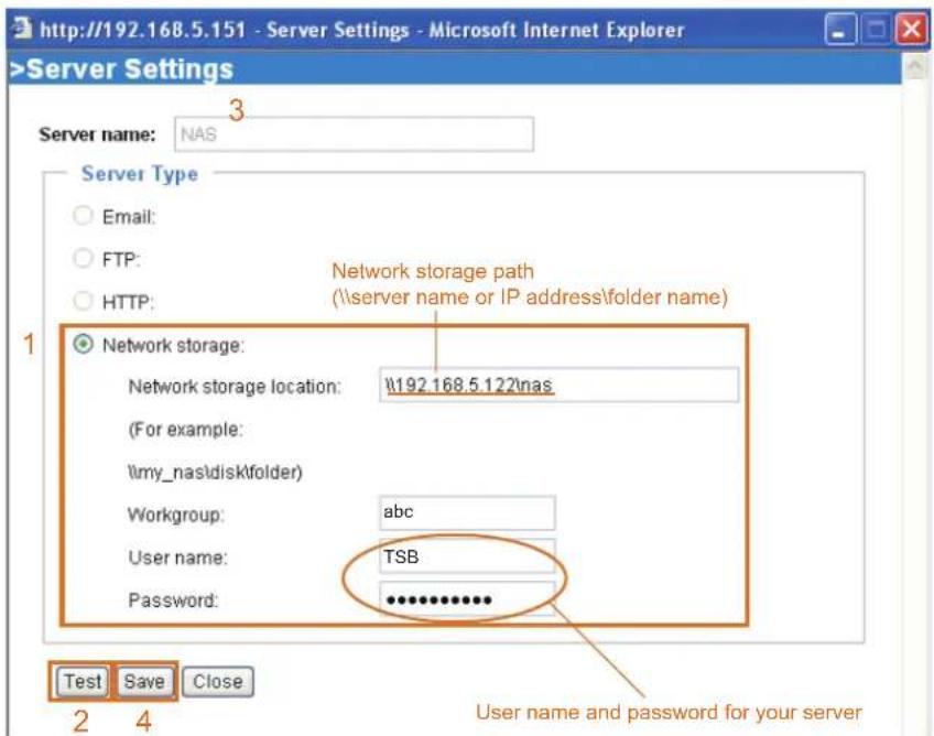
- Click Test to check the setting. The result will be shown in the pop-up window.
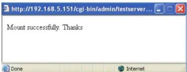

If successful, you will receive a test.txt file on the network storage server.
![NAS on ritali File Edit View Favorites Tools Help Back Search Folders Address \ritali\NAS File and Folder Tasks Rename this file Move this file Copy this file Publish this file to the Web E-mail this file Print this file Delete this file Other Places test.txt Text Document 1 KB test.txt - Notepad File Edit Format View Help [NOTIFICATION]The Result of Server Test of Your IP Camera](/content/2026/05/988175/images/7723973ca09680cbeb1ff5d9189848bae6b43c9c4e6d59ed79c08b2284a2d00a.jpg)
- Enter a server name.
- Click Save to complete the settings and click Close to exit the page.
Recording Settings
Click Add to open the recording setting page. In this page, you can define the recording source, recording schedule and recording capacity. A total of 2 recording settings can be configured.
![Recording Recording name: Video Enable this recording Priority: Normal Source: Stream1 Recording Schedule Sun Mon Tue Wed Thu Fri Sat Time Always From 00:00 to 24:00 [hh:mm] Destination SD Capacity: SD NAS Entire free space Limit recording size in 100 Mbytes File name prefix: Video_ Enable cyclic recording Reserved amount: 15 Mbytes Note: To enable recording notification please configure Application first Save Close](/content/2026/05/988175/images/7bdae52cdb16a5865453f300c3d224dd6b1e4396a386363e29d1d24a2856d9b9.jpg)
Recording name: Enter a name for the recording setting.
Enable this recording: Select this option to enable video recording.
Priority: Select the relative importance of this recording setting (High, Normal, and Low).
Source: Select the recording source (stream 1 \~ 4).
Recording Schedule: Specify the recording duration.
■ Select the days of the week.
■ Select the recording start and end times in 24-hr time format.
Destination: You can select the SD card or network storage that was set up for the recorded video files.
Capacity: You can choose either the entire free space available or limit the recording size. The recording size limit must be larger than the reserved amount for cyclic recording.
File name prefix: Enter the text that will be appended to the front of the file name.
Enable cyclic recording: If you check this item, when the maximum capacity is reached, the oldest file will be overwritten by the latest one. The reserved amount is reserved for cyclic recording to prevent malfunction. This value must be larger than 15 MBytes.
When completed, select Enable this recording. Click Save to enable the setting and click Close to exit this page. When the system begins recording, it will send the recorded files to the Network Storage. The new recording name will appear in the drop-down list on the recording page as shown below.
To remove a recording setting from the list, select a recording name from the drop-down list and click Delete.

■ Click Video (Name): Opens the Recording Settings page to modify.
■ Click ON (Status): The Status will become OFF and stop recording.
■ Click NAS (Destination): Opens the file list of recordings as shown below. For more information about folder naming rules, please refer to page 96 for details.

Local Storage Advanced Mode
This section explains how to manage the local storage on the Network Camera. Here you can view SD card status, search for recorded files to playback, download, etc.
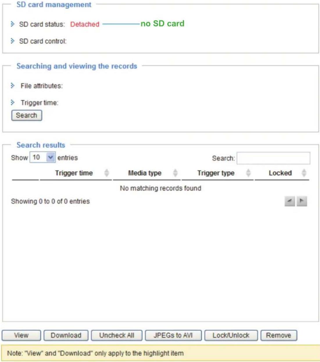
SD Card Management
SD card status: This column shows the status and reserved space of your SD card. Please remember to format the SD card when using for the first time.
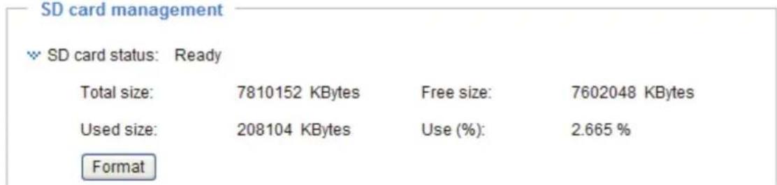
SD card control
■ Enable cyclic storage: Check this item if you want to enable cyclic recording. When the maximum capacity is reached, the oldest file will be overwritten by the latest one.

■ Enable automatic disk cleanup: Check this item and enter the number of days you wish to retain a file. For example, if you enter "7 days", the recorded files will be stored on the SD card for 7 days.
Click Save to enable your settings.
Searching and Viewing the Records
This column allows the user to set up search criteria for recorded data. If you do not select any criteria and click Search button, all recorded data will be listed in the Search Results cloumn.
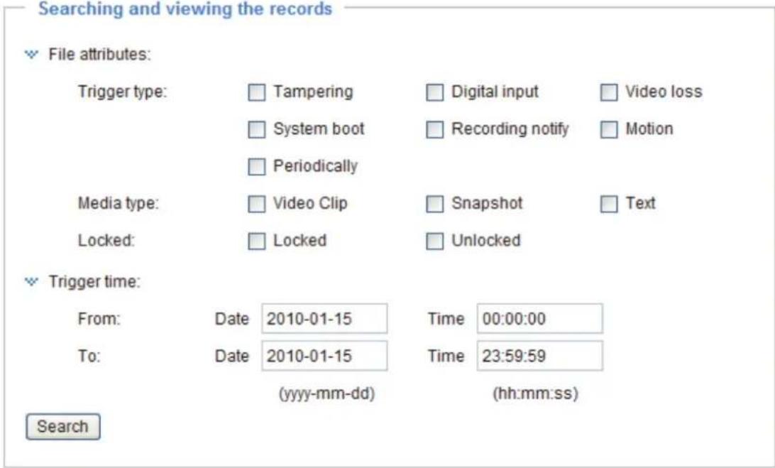
File attributes: Select one or more items as your search criteria.
Trigger time: Manually enter the time range you want to search.
Click Search and the recorded data corresponding to the search criteria will be listed in Search Results window.
Search Results
The following is an example of search results. There are four columns: Trigger time, Media type, Trigger type, and Locked. Click to sort the search results in either direction.
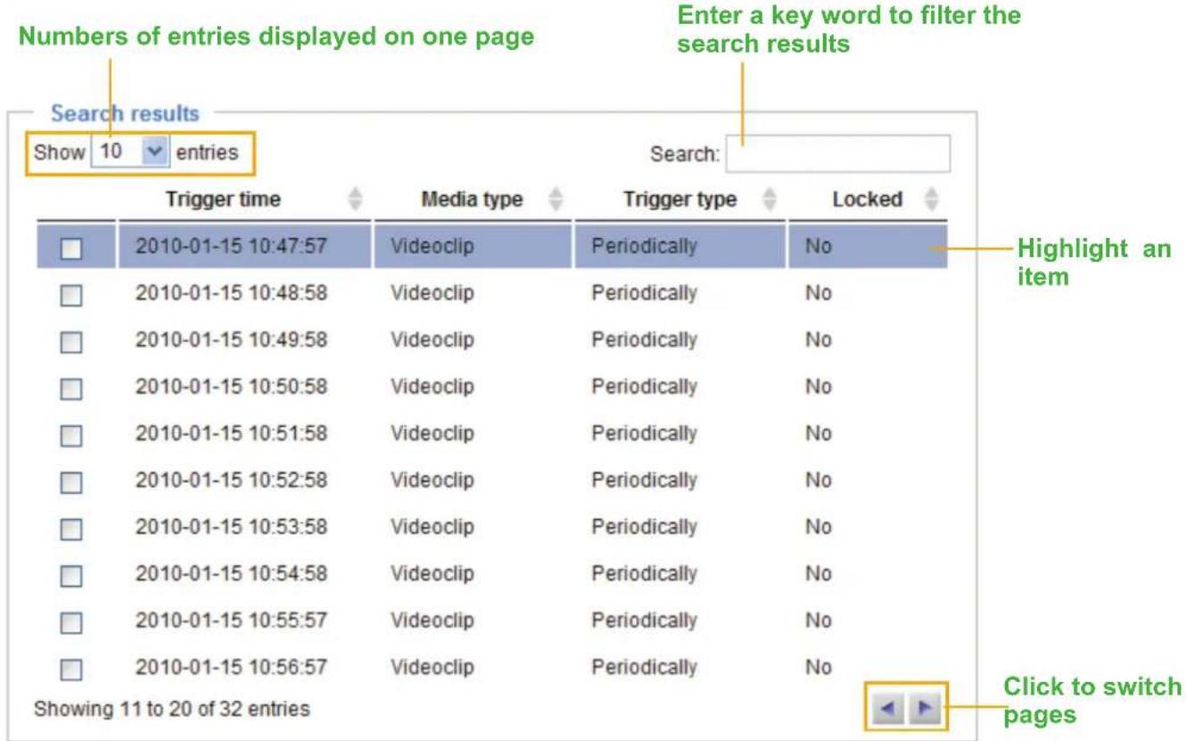

Note: "View" and "Download" only apply to the highlight item
View: Click on a search result which will highlight the selected item in purple as shown above. Click the View button and a media window will pop up to play back the selected file.
For example:
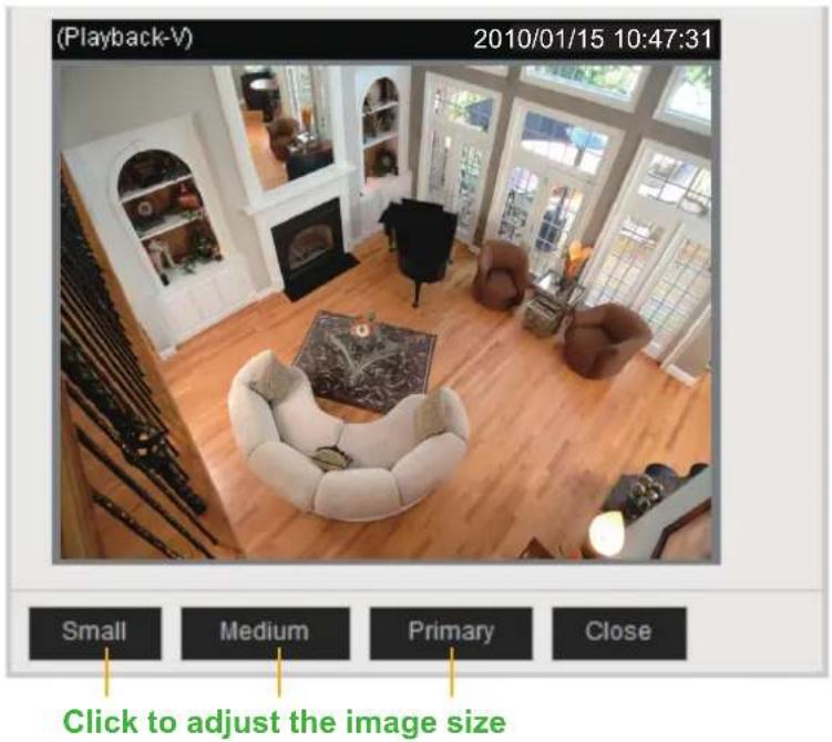
Download: Click on a search result to highlight the selected item in purple as shown above. Then click the Download button and a file download window will pop up for you to save the file.
JPEGs to AVI: This functions only applies to "JPEG" format files such as snapshots. You can select several snapshots from the list, then click this button. Those snapshots will be converted into an AVI file.
Lock/Unlock: Select the desired search results, then click this button. The selected items will become Locked, which will not be deleted during cyclic recoding. You can click again to unlock the selections. For example:

Remove: Select the desired search results, then click this button to delete the files.
NOTE
- There is a limit to the number of rewrites that is possible with the SD memory card. Replacing the SD memory card when performing periodic maintenance of the camera is recommended.
- Do not use 512MB and below SD memory cards.
- The camera system reserves approximately 60MB in SD memory cards. Any images are not recordable on this space.
- Carefully read the User's guide, precautions on use, and any other information supplied with a purchased memory card.
- An SD memory card can be used for the cyclic storage. The lifespan (number of rewrites possible) of an SD memory card is greatly affected by the capacity of the SD memory card.
- Do not use a memory card containing the data recorded by another device with the camera as this may result in the camera not functioning correctly.
- Do not modify, overwrite the data, or change the folder name of an SD memory card. It may result in the camera not to function correctly.
- If you unmount or remove the SD memory card from camera, you have to turn OFF the recording status in Recording window on page 100 and Application window on page 87.
System Log Advanced Mode
This section explains how to configure the Network Camera to send the system log to the remote server as backup.
Remote Log

You can configure the Network Camera to send the system log file to a remote server as a log message. When using this feature, the appropriate syslog server is required for receiving the system log message from the Network Camera.
Follow the steps below to set up the remote log:
- In the IP address text box, enter the IP address of the remote server.
- In the port text box, enter the port number of the remote server.
- When completed, select Enable remote log and click Save to enable the setting.
Current Log
This column displays the system's log in chronological order. The system log is stored in the Network Camera's buffer area and will be overwritten when reaching a certain amount.
The system log messages stored in the Network Camera will be all cleared after reboot or power down the Network Camera.
View Parameters Advanced Mode
The View Parameters page lists the entire system's parameters in alphabetical order. If you need technical assistance, please provide the information listed on this page.
Maintenance
This chapter explains how to restore the Network Camera to factory default, upgrade firmware version, etc.
Reboot
Reboot
Reboot the device
Reboot
This feature allows you to reboot the Network Camera, which takes about one minute to complete. When completed, the live video page will be displayed in your browser. The following message will be displayed during the reboot process.
The device is rebooting now. Your browser will reconnect to http://192.168.5.151:80/ If the connection fails, please manually enter the above IP address in your browser.

If the connection fails after rebooting, manually enter the IP address of the Network Camera in the address field to resume the connection.
Restore
Restore
Restore all settings to factory default except settings in

Network Type

Daylight Saving Time
Restore
This feature allows you to restore the Network Camera to factory default settings.
Network Type: Select this option to retain the Network Type settings (please refer to Network Type on page 45).
Daylight Saving Time: Select this option to retain the Daylight Saving Time settings (please refer to System on page 36)
If none of the options is selected, all settings will be restored to factory default.
The following message is displayed during the restoring process.
The device is rebooting now. Your browser will reconnect to http://192.168.5.151:80/ If the connection fails, please manually enter the above IP address in your browser.

Calibrate
Calibrate
Recalibrate the home position to the default center to recover the tolerance caused by some external forces.
Calibrate
This feature re-calibrate the home position to the default center to recover the any displacement caused by external forces. Please note that there is no confirm message box after clicking on Calibrate, and the Network Camera will calibrate immediately.
Export / Upload Files Advanced Mode
This feature allows you to Export / Upload daylight saving time rules, custom language files, and setting backup files.

Export daylight saving time configuration file: Click to set the start and end time of DST.
Follow the steps below to export:
- In the Export files column, click Export to export the daylight saving time configuration file from the Network Camera.
- A file download dialog will pop up as shown below. Click Open to review the XML file or click Save to store the file for editing.
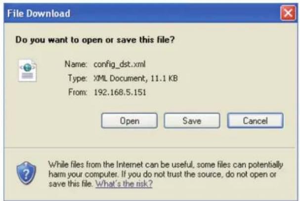
- Open the file with a text editor and locate your time zone; set the start and end time of DST. When completed, save the file.
In the example below, DST begins each year at 2:00 a.m. on the second Sunday in March and ends at 2:00 a.m. on the first Sunday in November.
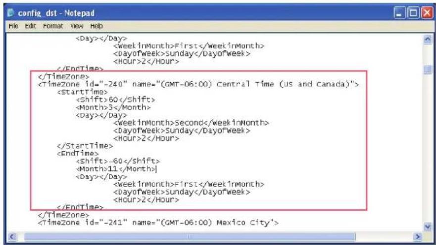
Upload daylight saving time rule: Click Browse... and specify the XML file to upload.
If the incorrect date and time are assigned, you will see the following warning message when uploading the file to the Network Camera.

The following message is displayed when attempting to upload an incorrect file format.

Export setting backup file: Click to export all parameters for the device and user-defined scripts.
Upload setting backup file: Click Browse... to upload a setting backup file. Please note that the model and firmware version of the device should be the same as the setting backup file. If you have set up a fixed IP or other special settings for your device, it is not suggested to upload a settings backup file.
Upgrade Firmware

This feature allows you to upgrade the firmware of your Network Camera. It takes a few minutes to complete the process.
Note: Do not power off the Network Camera during the upgrade!
Follow the steps below to upgrade the firmware:
- Download the latest firmware file from the TOSHIBA website. The file is in .pkg file format.
- Click Browse... and specify the firmware file.
- Click Upgrade. The Network Camera starts to upgrade and will reboot automatically when the upgrade completes.
If the upgrade is successful, you will see "Reboot system now!! This connection will close". After that, re-access the Network Camera.
The following message is displayed when the upgrade has succeeded.
Reboot system now!! This connection will close.
The following message is displayed when you have selected an incorrect firmware file.
Starting firmware upgrade... Do not power down the server during the upgrade. The server will restart automatically after the upgrade is completed. This will take about 1 - 5 minutes. Wrong PKG file format Unpack fail
Troubleshooting
Reboot and restore
If an operational problem occurred in the camera, please refer to the Reboot and Restore function on page 16.

Restoring the factory defaults will erase any previous settings.
Audio
When using multiple network cameras, restart Internet Explorer each time you switch the camera. Using the same Internet Explorer session for the multiple cameras may transmit multiple camera's audio.
External Microphone
The usable microphone is the Plug-in-power Condenser Microphones with 3.5mm Stereo mini-plug. And right angle plug is highly recommended.
Recommended system requirements
Windows ® XP, Windows Vista ® Business, Windows 7 ® Professional,
Internet Explorer Ver 8.0
Minimum of 2GHz CPU, 1GB RAM,
and 512MB Graphics adapter
Lens Focus
- This camera is using the pan focus lens. This camera comes into focus from 1.5m to infinite distance.
- The surrounding part of image is a bit out of focus compared to the central part, due to the lens spec. It is not failure.
- There may be a difference of focus if compared to the left, right, top and bottom of image. It is not failure.
WPS (Wi-Fi Protected Setup) : IK-WB16A-W only
When using WPS button, make sure the router settings first. WPS of IK-WB16A-W doesn't support WEP security mode.
Specifications
IK-WB16A
| Power supply 12V DC ± 10 %, PoE | |
| Consumption current 12V DC / 0.8 A | |
| Image pickup device 1/3.2 inch (4:3), CMOS Digital Image Sensor | |
| Full resolution Horizontal 1600, vertical 1200 pixels | |
| Scanning system Progressive | |
| Minimum object illuminance 2.0 lux / F1.8 (Max gain 4x, Exposure time 1/30)0.2 lux / F1.8 (Max gain 8x, Exposure time 1/5) | |
| White balance AWB | |
| Image size 1600x1200, 1280x960, 800x600, 640x480, 320x240,176 x 144 | |
| Image compression system JPEG, MPEG4 | |
| Image quality setting 6 levels | |
| Maximum frame rate at M-JPEG*1 30 fps at 800 x 600, 15 fps at 1600 x 1200 | |
| Maximum frame rate at MPEG 4*1 30 fps at 800 x 600, 10 fps at 1600 x 1200 | |
| SD card slot micro SD / SDHC | |
| Digital zoom Maximum 4 times | |
| Pan range 350 deg | |
| Tilt range 113 deg | |
| Preset position | 20 positions |
| Microphone in / Audio out*2 | MIC IN (plug-in-power 3.3v, 200kΩ) / AUDIO OUT (1Vrms) |
| I/O terminal | Input 1, output 1 |
| Network interface | 10Base-T / 100Base-TX, RJ45 connector,IEEE 802.3af (PoE compatible) |
| Protocols | TCP/IP, HTTP, UPnP, RTSP/RTP/RTCP, IGMP, SMTP, FTP,DHCP, NTP, DNS, DDNS, PPPoE, SNMP |
| OS | Windows® XP, Windows Vista® Business and Windows 7®Professional |
| Browser | Internet Explorer® Ver. 8.0 |
| Operating temperature | 14°F to 122°F (-10°C to 50°C) |
| Operating humidity | 20 % to 80 % |
| Storage temperature -4°F to 140°F | (-20°C to 60°C) |
| Storage humidity | 90 % or less |
| Weight | 480 g (1.06 lbs) |
| Dimensions | 5.2(W) x 5.6(D) x 5.1(H) inches (131(W) x 140(D) x 128(H)mm) (excluding protrusion) |
| Accessories | User's manual and install software (CD-ROM) (1),Quick start guide and important safeguards (1),AC adapter (1), Warranty (1), Screws, Ceiling mount bracket(1sets), LAN Cable(1), RJ45 female adaptor(1),Alignment sticker(1) |
- Designs and specifications may change without prior notice for better improvement.
- Screens, photos, illustrations and other diagrams contained in this user's manual may slightly change from actual ones.
*1: Varies in accordance with the object, image quality, network environment and performance of the personal computer used.
*2: The sound may not be clear depending on the conditions of the lines.
Specifications
IK-WB16A-W
| Power supply 12V DC ± 10 % | |
| Consumption current 12V DC / 0.9 A | |
| Image pickup device 1/3.2 inch (4:3), CMOS Digital Image Sensor | |
| Full resolution Horizontal 1600, vertical 1200 pixels | |
| Scanning system Progressive | |
| Minimum object illuminance 2.0 lux / F1.8 (Max gain 4x, Exposure time 1/30)0.2 lux / F1.8 (Max gain 8x, Exposure time 1/5) | |
| White balance AWB | |
| Image size 1600x1200, 1280x960, 800x600, 640x480, 320x240,176 x 144 | |
| Image compression system JPEG, MPEG4 | |
| Image quality setting 6 levels | |
| Maximum frame rate at M-JPEG*1 30 fps at 800 x 600, 15 fps at 1600 x 1200 | |
| Maximum frame rate at MPEG 4*1 30 fps at 800 x 600, 10 fps at 1600 x 1200 | |
| SD card slot micro SD / SDHC | |
| Digital zoom Maximum 4 times | |
| Pan range 350 deg | |
| Tilt range 113 deg | |
| Preset position | 20 positions |
| Microphone in / Audio out*2 | MIC IN (plug-in-power 3.3v, 200kΩ) / AUDIO OUT (1Vrms) |
| I/O terminal | Input 1, output 1 |
| Network interface | 10Base-T / 100Base-TX, RJ45 connector,Wireless LAN (IEEE 802.11b, 802.11g, and 802.11n) |
| Protocols | TCP/IP, HTTP, UPnP, RTSP/RTP/RTCP, IGMP, SMTP, FTP,DHCP, NTP, DNS, DDNS, PPPoE, SNMP |
| OS | Windows® XP, Windows Vista® Business and Windows 7®Professional |
| Browser | Internet Explorer® Ver. 8.0 |
| Operating temperature | 14°F to 122°F (-10°C to 50°C) |
| Operating humidity | 20 % to 80 % |
| Storage temperature -4°F to 140°F (-20°C to 60°C) | |
| Storage humidity | 90 % or less |
| Weight | 505 g (1.11 lbs) |
| Dimensions | 5.2(W) x 5.6(D) x 5.1(H) inches (131(W) x 140(D) x 128(H)mm) (excluding protrusion) |
| Accessories | User's manual and install software (CD-ROM) (1),Quick start guide and important safeguards (1),AC adapter (1), Warranty (1), Screws, Ceiling mount bracket(1sets), LAN Cable(1), RJ45 female adaptor(1),Alignment sticker(1), Antenna(2) |
- Designs and specifications may change without prior notice for better improvement.
- Screens, photos, illustrations and other diagrams contained in this user's manual may slightly change from actual ones.
*1: Varies in accordance with the object, image quality, network environment and performance of the personal computer used.
*2: The sound may not be clear depending on the conditions of the lines.
Appearance Diagram
IK-WB16A

inches (mm)
Appearance Diagram
IK-WB16A-W

natural_image
Technical line drawing of a mechanical component with concentric rings and mounting holes (no text or symbols)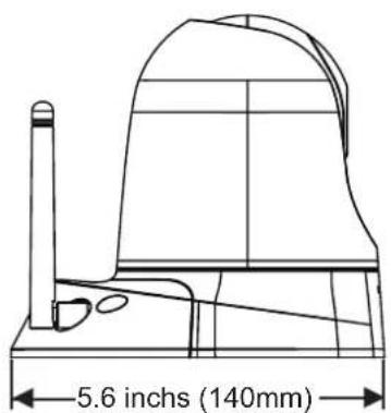

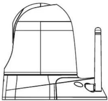
natural_image
Technical line drawing of a mechanical component or bracket (no text or symbols)
natural_image
Technical line drawing of a mechanical support structure (no text or symbols)inches (mm)
Technology License Notice
MPEG-4 AAC Technology
THIS PRODUCT IS LICENSED UNDER THE MPEG-4 AAC AUDIO PATENT LICENSE. THIS PRODUCT MAY NOT BE DECOMPILED, REVERSE-ENGINEERED OR COPIED, EXCEPT REGARD TO PC SOFTWARE, YOU MAY MAKE SINGLE COPIES FOR ARCHIVAL PURPOSES.FOR MORE INFORMATION, PLEASE REFER TO HTTP://WWW.VIALICENSING.COM.
MPEG-4 Visual Technology
THIS PRODUCT IS LICENSED UNDER THE MPEG-4 VISUAL PATENT PORTFOLIO LICENSE FOR THE PERSONAL AND NON-COMMERCIAL USE OF A CONSUMER FOR (i) ENCODING VIDEO IN COMPLIANCE WITH THE MPEG-4 VISUAL STANDARD ("MPEG-4 VIDEO") AND/OR (ii) DECODING MPEG-4 VIDEO THAT WAS ENCODED BY A CONSUMER ENGAGED IN A PERSONAL AND NON-COMMERCIAL ACTIVITY AND/OR WAS OBTAINED FROM A VIDEO PROVIDER LICENSED BY MPEG LA TO PROVIDE MPEG-4 VIDEO. NO LICENSE IS GRANTED OR SHALL BE IMPLIED FOR ANY OTHER USE. ADDITIONAL INFORMATION INCLUDING THAT RELATING TO PROMOTIONAL, INTERNAL AND COMMERCIAL USES AND LICENSING MAY BE OBTAINED FROM MPEG LA, LLC. SEE HTTP://WWW.MPEGLA.COM.
AMR-NB Standard
THIS PRODUCT IS LICENSED UNDER THE AMR-NB STANDARD PATENT LICENSE AGREEMENT. WITH RESPECT TO THE USE OF THIS PRODUCT, THE FOLLOWING LICENSORS' PATENTS MAY APPLY:
TELEFONAKIEBOLAGET ERICSSON AB: US PAT. 6192335; 6275798; 6029125; 6424938; 6058359. NOKIA CORPORATION: US PAT. 5946651; 6199035. VOICEAGE CORPORATION: AT PAT. 0516621; BE PAT. 0516621; CA PAT. 2010830; CH PAT. 0516621; DE PAT. 0516621; DK PAT. 0516621; ES PAT. 0516621; FR PAT. 0516621; GB PAT. 0516621; GR PAT. 0516621; IT PAT. 0516621; LI PAT. 0516621; LU PAT. 0516621; NL PAT. 0516621; SE PAT 0516621; US PAT 5444816; AT PAT. 819303/AT E 198805T1; AU PAT. 697256; BE PAT. 819303; BR PAT. 9604838-7; CA PAT. 2216315; CH PAT. 819303; CN PAT. ZL96193827.7; DE PAT. 819303/DE69611607T2; DK PAT. 819303; ES PAT. 819303; EP PAT. 819303; FR PAT. 819303; GB PAT. 819303; IT PAT. 819303; JP PAT. APP. 8-529817; NL PAT. 819303; SE PAT. 819303; US PAT. 5664053. THE LIST MAY BE UPDATED FROM TIME TO TIME BY LICENSORS AND A CURRENT VERSION OF WHICH IS AVAILABLE ON LICENSOR'S WEBSITE AT HTTP://WWW.VOICEAGE.COM.
About the software
This product contains a piece of software licensed to TOSHIBA CORPORATION (hereafter TOSHIBA) by a third party. The copyright and other intellectual property rights of the software are held by this third party or the licensor. The software is protected by the Copyright Law, Universal Copyright Convention, and other intellectual property laws and agreements. The permission of Toshiba and the third party must therefore be obtained before the software can be reproduced. Contact Toshiba if you need it for more information at http://www.toshibasecurity.com/support/firmware.jsp.
End-user License Agreement on Free Software Components Used in the TOSHIBA Network Camera
GNU GENERAL PUBLIC LICENSE
Version 2, June 1991
Copyright (C) 1989, 1991 Free Software Foundation, Inc.
51 Franklin Street, Fifth Floor, Boston, MA 02110-1301 USA
Everyone is permitted to copy and distribute verbatim copies of this license document, but changing it is not allowed.
Preamble
The licenses for most software are designed to take away your freedom to share and change it. By contrast, the GNU General Public License is intended to guarantee your freedom to share and change free software--to make sure the software is free for all its users. This General Public License applies to most of the Free Software Foundation's software and to any other program whose authors commit to using it. (Some other Free Software Foundation software is covered by the GNU Lesser General Public License instead.) You can apply it to your programs, too.
When we speak of free software, we are referring to freedom, not price. Our General Public Licenses are designed to make sure that you have the freedom to distribute copies of free software (and charge for this service if you wish), that you receive source code or can get it if you want it, that you can change the software or use pieces of it in new free programs; and that you know you can do these things.
To protect your rights, we need to make restrictions that forbid anyone to deny you these rights or to ask you to surrender the rights. These restrictions translate to certain responsibilities for you if you distribute copies of the software, or if you modify it.
For example, if you distribute copies of such a program, whether gratis or for a fee, you must give the recipients all the rights that you have. You must make sure that they, too, receive or can get the source code. And you must show them these terms so they know their rights.
We protect your rights with two steps: (1) copyright the software, and (2) offer you this license which gives you legal permission to copy, distribute and/or modify the software.
Also, for each author's protection and ours, we want to make certain that everyone understands that there is no warranty for this free software. If the software is modified by someone else and passed on, we want its recipients to know that what they have is not the original, so that any problems introduced by others will not reflect on the original authors' reputations.
Finally, any free program is threatened constantly by software patents. We wish to avoid the danger that redistributors of a free program will individually obtain patent licenses, in effect making the program proprietary. To prevent this, we have made it clear that any patent must be licensed for everyone's free use or not licensed at all.
The precise terms and conditions for copying, distribution and modification follow.
GNU GENERAL PUBLIC LICENSE
TERMS AND CONDITIONS FOR COPYING, DISTRIBUTION AND MODIFICATION
- This License applies to any program or other work which contains a notice placed by the copyright holder saying it may be distributed under the terms of this General Public License. The "Program", below, refers to any such program or work, and a "work based on the Program" means either the Program or any derivative work under copyright law: that is to say, a work containing the Program or a portion of it, either verbatim or with modifications and/or translated into another language. (Hereinafter, translation is included without limitation in the term "modification".) Each licensee is addressed as "you".
Activities other than copying, distribution and modification are not covered by this License; they are outside its scope. The act of running the Program is not restricted, and the output from the Program is covered only if its contents constitute a work based on the Program (independent of
having been made by running the Program). Whether that is true depends on what the Program does.
- You may copy and distribute verbatim copies of the Program's source code as you receive it, in any medium, provided that you conspicuously and appropriately publish on each copy an appropriate copyright notice and disclaimer of warranty; keep intact all the notices that refer to this License and to the absence of any warranty; and give any other recipients of the Program a copy of this License along with the Program.
You may charge a fee for the physical act of transferring a copy, and you may at your option offer warranty protection in exchange for a fee.
- You may modify your copy or copies of the Program or any portion of it, thus forming a work based on the Program, and copy and distribute such modifications or work under the terms of Section 1 above, provided that you also meet all of these conditions:
a) You must cause the modified files to carry prominent notices stating that you changed the files and the date of any change.
b) You must cause any work that you distribute or publish, that in whole or in part contains or is derived from the Program or any part thereof, to be licensed as a whole at no charge to all third parties under the terms of this License.
c) If the modified program normally reads commands interactively when run, you must cause it, when started running for such interactive use in the most ordinary way, to print or display an announcement including an appropriate copyright notice and a notice that there is no warranty (or else, saying that you provide a warranty) and that users may redistribute the program under these conditions, and telling the user how to view a copy of this License. (Exception: if the Program itself is interactive but does not normally print such an announcement, your work based on the Program is not required to print an announcement.)
These requirements apply to the modified work as a whole. If identifiable sections of that work are not derived from the Program, and can be reasonably considered independent and separate works in themselves, then this License, and its terms, do not apply to those sections when you distribute them as separate works. But when you distribute the same sections as part of a whole which is a work based on the Program, the distribution of the whole must be on the terms of this License, whose permissions for other licensees extend to the entire whole, and thus to each and every part regardless of who wrote it.
Thus, it is not the intent of this section to claim rights or contest your rights to work written entirely by you; rather, the intent is to exercise the right to control the distribution of derivative or collective works based on the Program.
In addition, mere aggregation of another work not based on the Program with the Program (or with a work based on the Program) on a volume of a storage or distribution medium does not bring the other work under the scope of this License.
- You may copy an d distribute the Program (or a work based on it, under Section 2) in object code or executable form under the terms of Sections 1 and 2 above provided that you also do one of the following:
a) Accompany it with the complete corresponding machine-readable source code, which must be distributed under the terms of Sections 1 and 2 above on a medium customarily used for software interchange; or,
b) Accompany it with a written offer, valid for at least three years, to give any third party, for a charge no more than your cost of physically performing source distribution, a complete machine-readable copy of the corresponding source code, to be distributed under the terms of Sections 1 and 2 above on a medium customarily used for software interchange; or,
c) Accompany it with the information you received as to the offer to distribute corresponding source code. (This alternative is allowed only for noncommercial distribution and only if you received the program in object code or executable form with such an offer, in accord with Subsection b above.)
The source code for a work means the preferred form of the work for making modifications to it. For an executable work, complete source code means all the source code for all modules it contains, plus any associated interface definition files, plus the scripts used to control compilation and installation of the executable. However, as a special exception, the source code distributed need not include anything that is normally distributed (in either source or binary form) with the major components (compiler, kernel, and so on) of the operating system on which the executable runs, unless that component itself accompanies the executable.
If distribution of executable or object code is made by offering access to copy from a designated place, then offering equivalent access to copy the source code from the same place counts as distribution of the source code, even though third parties are not compelled to copy the source along with the object code.
-
You may not copy, modify, sublicense, or distribute the Program except as expressly provided under this License. Any attempt otherwise to copy, modify, sublicense or distribute the Program is void, and will automatically terminate your rights under this License. However, parties who have received copies, or rights, from you under this License will not have their licenses terminated so long as such parties remain in full compliance.
-
You are not required to accept this License, since you have not signed it. However, nothing else grants you permission to modify or distribute the Program or its derivative works. These actions are prohibited by law if you do not accept this License. Therefore, by modifying or distributing the Program (or any work based on the Program), you indicate your acceptance of this License to do so, and all its terms and conditions for copying, distributing or modifying the Program or works based on it.
-
Each time you redistribute the Program (or any work based on the Program), the recipient automatically receives a license from the original licensor to copy, distribute or modify the Program subject to these terms and conditions. You may not impose any further restrictions on the recipients' exercise of the rights granted herein. You are not responsible for enforcing compliance by third parties to this License.
-
If, as a consequence of a court judgment or allegation of patent infringement or for any other reason (not limited to patent issues), conditions are imposed on you (whether by court order, agreement or otherwise) that contradict the conditions of this License, they do not excuse you from the conditions of this License. If you cannot distribute so as to satisfy simultaneously your obligations under this License and any other pertinent obligations, then as a consequence you may not distribute the Program at all. For example, if a patent license would not permit royalty-free redistribution of the Program by all those who receive copies directly or indirectly through you, then the only way you could satisfy both it and this License would be to refrain entirely from distribution of the Program.
If any portion of this section is held invalid or unenforceable under any particular circumstance, the balance of the section is intended to apply and the section as a whole is intended to apply in other circumstances.
It is not the purpose of this section to induce you to infringe any patents or other property right claims or to contest validity of any such claims; this section has the sole purpose of protecting the integrity of the free software distribution system, which is implemented by public license practices. Many people have made generous contributions to the wide range of software distributed through that system in reliance on consistent application of that system; it is up to the author/donor to decide if he or she is willing to distribute software through any other system and
a licensee cannot impose that choice.
This section is intended to make thoroughly clear what is believed to be a consequence of the rest of this License.
- If the distribution and/or use of the Program is restricted in certain countries either by patents or by copyrighted interfaces, the original copyright holder who places the Program under this License may add an explicit geographical distribution limitation excluding those countries, so that distribution is permitted only in or among countries not thus excluded. In such case, this License incorporates the limitation as if written in the body of this License.
- The Free Software Foundation may publish revised and/or new versions of the General Public License from time to time. Such new versions will be similar in spirit to the present version, but may differ in detail to address new problems or concerns.
Each version is given a distinguishing version number. If the Program specifies a version number of this License which applies to it and "any later version", you have the option of following the terms and conditions either of that version or of any later version published by the Free Software Foundation. If the Program does not specify a version number of this License, you may choose any version ever published by the Free Software Foundation.
- If you wish to incorporate parts of the Program into other free programs whose distribution conditions are different, write to the author to ask for permission. For software which is copyrighted by the Free Software Foundation, write to the Free Software Foundation; we sometimes make exceptions for this. Our decision will be guided by the two goals of preserving the free status of all derivatives of our free software and of promoting the sharing and reuse of software generally.
NO WARRANTY
- BECAUSE THE PROGRAM IS LICENSED FREE OF CHARGE, THERE IS NO WARRANTY FOR THE PROGRAM, TO THE EXTENT PERMITTED BY APPLICABLE LAW. EXCEPT WHEN OTHERWISE STATED IN WRITING THE COPYRIGHT HOLDERS AND/OR OTHER PARTIES PROVIDE THE PROGRAM "AS IS" WITHOUT WARRANTY OF ANY KIND, EITHER EXPRESSED OR IMPLIED, INCLUDING, BUT NOT LIMITED TO, THE IMPLIED WARRANTIES OF MERCHANTABILITY AND FITNESS FOR A PARTICULAR PURPOSE. THE ENTIRE RISK AS TO THE QUALITY AND PERFORMANCE OF THE PROGRAM IS WITH YOU. SHOULD THE PROGRAM PROVE DEFECTIVE, YOU ASSUME THE COST OF ALL NECESSARY SERVICING, REPAIR OR CORRECTION.
- IN NO EVENT UNLESS REQUIRED BY APPLICABLE LAW OR AGREED TO IN WRITING WILL ANY COPYRIGHT HOLDER, OR ANY OTHER PARTY WHO MAY MODIFY AND/OR REDISTRIBUTE THE PROGRAM AS PERMITTED ABOVE, BE LIABLE TO YOU FOR DAMAGES, INCLUDING ANY GENERAL, SPECIAL, INCIDENTAL OR CONSEQUENTIAL DAMAGES ARISING OUT OF THE USE OR INABILITY TO USE THE PROGRAM (INCLUDING BUT NOT LIMITED TO LOSS OF DATA OR DATA BEING RENDERED INACCURATE OR LOSSES SUSTAINED BY YOU OR THIRD PARTIES OR A FAILURE OF THE PROGRAM TO OPERATE WITH ANY OTHER PROGRAMS), EVEN IF SUCH HOLDER OR OTHER PARTY HAS BEEN ADVISED OF THE POSSIBILITY OF SUCH DAMAGES.
END OF TERMS AND CONDITIONS
How to Apply These Terms to Your New Programs
If you develop a new program, and you want it to be of the greatest possible use to the public, the best way to achieve this is to make it free software which everyone can redistribute and change under these terms.
To do so, attach the following notices to the program. It is safest to attach them to the start of each source file to most effectively convey the exclusion of warranty; and each file should have at least the "copyright" line and a pointer to where the full notice is found.
Copyright (C)
This program is free software; you can redistribute it and/or modify it under the terms of the GNU General Public License as published by the Free Software Foundation; either version 2 of the License, or (at your option) any later version.
This program is distributed in the hope that it will be useful, but WITHOUT ANY WARRANTY; without even the implied warranty of MERCHANTABILITY or FITNESS FOR A PARTICULAR PURPOSE. See the GNU General Public License for more details.
You should have received a copy of the GNU General Public License along with this program; if not, write to the Free Software Foundation, Inc., 51 Franklin Street, Fifth Floor, Boston, MA 02110-1301 USA
Also add information on how to contact you by electronic and paper mail.
If the program is interactive, make it output a short notice like this when it starts in an interactive mode:
Gnomovision version 69, Copyright (C) year name of author
Gnomovision comes with ABSOLUTELY NO WARRANTY; for details type 'show w'.
This is free software, and you are welcome to redistribute it under certain conditions; type 'show c' for details.
The hypothetical commands `show w' and `show c' should show the appropriate parts of the General Public License. Of course, the commands you use may be called something other than `show w' and `show c'; they could even be mouse-clicks or menu items--whatever suits your program.
You should also get your employer (if you work as a programmer) or your school, if any, to sign a "copyright disclaimer" for the program, if necessary. Here is a sample; alter the names:
Yoyodyne, Inc., hereby disclaims all copyright interest in the program 'Gnomovision' (which makes passes at compilers) written by James Hacker.
Ty Coon, President of Vice
This General Public License does not permit incorporating your program into proprietary programs. If your program is a subroutine library, you may consider it more useful to permit linking proprietary applications with the library. If this is what you want to do, use the GNU Lesser General Public License instead of this License.

- Leading Innovation >>>
- Model: IK-WB16A / IK-WB16A-W
- User's Manual
- Introduction
- FCC (USA)-INFORMATION
- Terms and Trademarks
- NOTE
- Important Safeguards
- Read Instructions
- Retain Instructions
- Warnings
- Follow Instructions
- Cleaning
- Attachments
- Water and Moisture
- Accessories
- Ventilation
- Power Sources
- Power-Cord Protection
- Installation
- Lightning
- Overloading
- Object and Liquid Entry
- Servicing
- Damage Requiring Service
- Replacement Parts
- Safety Check
- When using a wireless LAN function (IK-WB16A-W):
- If the use of a wireless LAN function interferes with another device's electromagnetic signals, cease use immediately.(IK-WB16A-W)
- Important Safeguards (Cont.)
- WARNING:
- FIELD INSTALLATION MARKING:
- Notes on Use and Installation
- Precautions for Use
- Disclaimer
- Copyright and Right of Portrait
- Protection of Personal Information
- Usage Limitation
- Wireless LAN and Your Health
- AC Adapter
- Specifications
- AC adapter (DSA-20P-10)
- Package Contents
- Physical Description
- Front Panel
- Back Panel
- General I/O Terminal Block
- Status LED
- WPS/Reset
- SD/SDHC Card and Capacity
- Installation
- Hardware Installation
- Network Deployment
- Setting up the Network Camera over the Internet
- Set up the Network Camera through Power over Ethernet (PoE) (IK-WB16A only)
- When using a PoE-enabled switch
- When using a non-PoE switch
- Set up the Network Camera through Wireless Connection (IK-WB16A-W only)
- Software Installation
- Ready to Use
- Accessing the Network Camera
- Using Web Browsers
- Using RTSP Players
- Using 3GPP-compatible Mobile Devices
- Main Page
- TOSHIBA Logo
- Host Name
- Camera Control Area
- Configuration Area
- Live Video Window
- Client Settings
- MPEG-4 Media Options
- MPEG-4 Protocol Options
- MP4 Saving Options
- Configuration
- Basic Mode
- Advanced Mode
- System
- System Time
- DI and DO
- Security
- Root Password
- Manage Privilege
- Manage User
- HTTPS (Hypertext Transfer Protocol over SSL) Advanced Mode
- Enable HTTPS
- Create and Install Certificate Method
- Create self-signed certificate automatically
- Create self-signed certificate manually
- SNMP (Simple Network Management Protocol) Advanced Mode
- SNMP Configuration
- Enable SNMPv1, SNMPv2c
- Enable SNMPv3
- Network
- Network Type
- LAN
- Save
- PPPoE (Point-to-point over Ethernet)
- Enable IPv6
- Refers to Ethernet
- IEEE 802.1x Advanced Mode
- IEEE 802.1x
- Enable 802.1x
- EAP-TLS
- QoS (Quality of Service) Advanced Mode
- Requirements for QoS
- QoS models
- CoS (the VLAN 802.1p model)
- QoS/DSCP (the DiffServ model)
- HTTP Advanced Mode
- HTTPS
- Two way audio
- FTP
- RTSP Streaming
- Wireless LAN (IK-WB16A-W only)
- DDNS
- DDNS: Dynamic domain name service
- Access List Advanced Mode
- General Settings
- Filter
- Administrator IP address
- Audio and Video
- Video Settings
- Options of Video Advanced Mode
- Image Settings Advanced Mode
- ■ Auto
- - Keep current value
- Image Adjustment
- Enable Edge Enhancement
- Enable Noise Reduction
- Sensor Settings Advanced Mode
- Exposure
- Cropping Setting Advanced Mode
- Cropping setting
- Video quality settings for stream 1 \~ 4 Advanced Mode Click the items to display the detailed video quality settings.
- ■ Frame size
- ■ Maximum frame rate
- ■ Intra frame period
- ■ Video quality
- Audio Settings
- Motion Detection
- For example:
- Camera Tampering Detection
- Camera Control
- Preset Positions
- Home page in PTZ Mode
- Patrol Settings
- Homepage Layout Advanced Mode
- Preview
- Logo
- Theme Options
- Application Advanced Mode
- Event Settings
- Trigger
- Event Schedule
- Action
- ■ Video motion detection
- ■ Periodically
- ■ Digital input
- ■ System boot
- ■ Camera tampering detection
- ■ Trigger digital output for □ seconds
- ■ Move to preset location
- ■ Add Server / Add Media
- Server Settings
- Server Type
- Media Settings
- Media Type
- The format is: HH (24r)
- The format is: File name prefix + Minute (mm)
- Recording Advanced Mode
- Recording Settings
- Network Storage Setting
- Local Storage Advanced Mode
- SD Card Management
- SD card control
- Searching and Viewing the Records
- Search Results
- System Log Advanced Mode
- Remote Log
- Current Log
- View Parameters Advanced Mode
- Maintenance
- Reboot
- Restore
- Calibrate
- Export / Upload Files Advanced Mode
- Upgrade Firmware
- Troubleshooting
- Reboot and restore
- Audio
- External Microphone
- Recommended system requirements
- Lens Focus
- WPS (Wi-Fi Protected Setup) : IK-WB16A-W only
- Appearance Diagram
- Technology License Notice
- MPEG-4 AAC Technology
- MPEG-4 Visual Technology
- AMR-NB Standard
- About the software
- End-user License Agreement on Free Software Components Used in the TOSHIBA Network Camera
- GNU GENERAL PUBLIC LICENSE
- Preamble
- TERMS AND CONDITIONS FOR COPYING, DISTRIBUTION AND MODIFICATION
- NO WARRANTY
- END OF TERMS AND CONDITIONS
Brand : TOSHIBA
Model : IK-WB16A
Category : Security Camera