NXA-TTS43X - Flat Screen Mount AMX - Free user manual and instructions
Find the device manual for free NXA-TTS43X AMX in PDF.


| Product Type | Table-Top Stand for Flat Panel |
| Brand | AMX |
| Model | NXA-TTS43X |
| Compatible Enclosures | NXA-TTS43X-BL, NXA-TTS500-BL |
| Mounting Type | Surface mount (flush) |
| Mounting Hole Diameter | 0.166" (4.22 mm) |
| Number of Mounting Holes | 3 |
| Cable Knockout | Yes, on bottom panel |
| Strain Relief Accessories | Cable Strain Relief (45-0004-04) and Strain Relief Bracket (62-1800-06) |
| Rubber Feet | Yes, removable (two rear feet cover mounting holes) |
| Material | Plastic and metal |
| Color | Black (-BL suffix) |
| Compatible Devices | Touch panels, keypads, ControlPads (size up to 4.3") |
| Installation Type | Surface mount with cable management |
| Tools Required | Flat-head screwdriver, drill for mounting holes |
| Documentation | Installation Guide specific to TTS model (e.g., NXA-TTS43X-BL Installation Guide) |
| Additional Features | Secure surface-mount installation, three mounting holes, internal cable routing |
Frequently Asked Questions - NXA-TTS43X AMX
User questions about NXA-TTS43X AMX
0 question about this device. Answer the ones you know or ask your own.
Ask a new question about this device
Download the instructions for your Flat Screen Mount in PDF format for free! Find your manual NXA-TTS43X - AMX and take your electronic device back in hand. On this page are published all the documents necessary for the use of your device. NXA-TTS43X by AMX.
USER MANUAL NXA-TTS43X AMX
Each of the TTS Table-Top Stands features a Cable Knockout and three mounting holes on the bottom panel that allow you to provide a secure surface-mount installation.
When surface mounting the TTS, all cabling will enter the TTS enclosure through the knockout on the bottom panel, using strain relief inside the enclosure (FIG. 1).
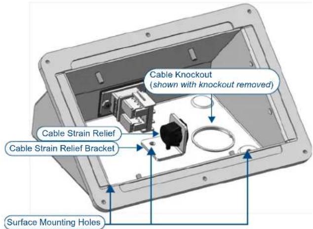
FIG. 1 Cable Knockout, Strain Relief and Surface Mounting Holes on TTS Enclosures
Note that in this type of installation, the rear panel connectors on the TTS are not used, since the cables entering the enclosure through the bottom panel connect directly to the Touch Panel, Keypad(s) or ControlPad installed in the Table-Top Stand.
Strain Relief Accessories
Included with each TTS Table-Top Stand is a cable Strain Relief and Strain Relief Bracket that mount inside the TTS enclosure:
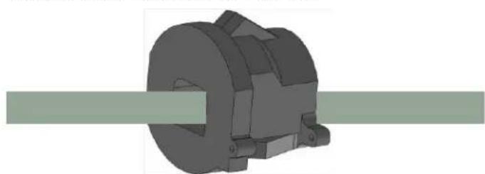
Cable Strain Relief (45-0004-04)
The Cable Strain Relief (FIG. 2) mounts onto the cable.
natural_image
3D mechanical component with cylindrical and flanged features, no visible text or symbolsFIG. 2 Cable Strain Relief (45-0004-04)
Strain Relief Bracket (62-1800-06)
The Strain Relief Bracket (FIG. 3) mounts to the bottom panel of the TTS enclosure, using the center mounting hole.
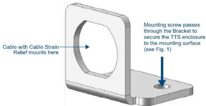
FIG. 3 Strain Relief Bracket (62-1800-06)
Note that the screw that secures the Strain Relief Bracket also serves as one of three mounting screws that secure the TTS enclosure to the mounting surface.
Preparing the Mounting Surface
- Establish the desired location and position for the installation.
Refer to FIG. 4 and FIG. 5 for the dimensions of the bottom panel and the location of the three mounting holes.
The mounting holes are 0.166" (4.22 mm). See "Mounting Specifications" for details.
- Drill three mounting holes into the surface.
Mounting Specifications
The following illustrations provide detailed dimensions of the bottom panel of the TTS Enclosures.
NXA-TTS43X-BL and NXA-TTS500-BL
The NXA-TTS43X-BL and NXA-TTS500-BL share the same TTS enclosure (FIG. 4):
![([100.91] 3.973 ( [40.64 ] 1.600 ( [4.22 ] 3X φ.166 ( [26.99 ] 1.063 ( [34.93 ] 1.375 ( [33.02 ] 1.300](/content/2026/05/987754/images/51a5192d497b1619150b0b0e6b9b5f20cb71750db4de77dc834c796ba9273649.jpg)
FIG. 4 Bottom panel specifications - NXA-TTS43X-BL and NXA-TTS500-BL
MET-TTS1/2/3-BL and AP-TTS16-BL
The MET-TTS1/2/3-BL and AP-TTS16-BL share the same TTS enclosure (FIG. 5):
![([100.91] 3.973 ( [40.64 ] 1.600 ( [4.22 ] 3X φ.166 ( [26.99 ] 1.063 ( [34.93 ] 1.375 ( [33.02 ] 1.300](/content/2026/05/987754/images/4ef5d7425be630f29131fb881c0da18379e653748b7fda2f7e6e3029eb2b4d83.jpg)
FIG. 5 Bottom panel specifications - MET-TTS123-BL and AP-TTS16-BL
Secure Surface-Mounting
- Use a flat-head screwdriver to remove the rubber feet. Note that two of the surface mounting holes are located beneath the two rear rubber feet (FIG. 6).
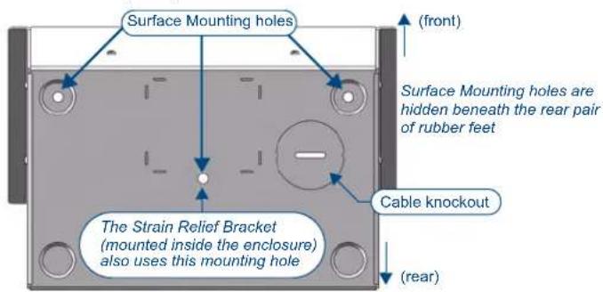
FIG. 6 Bottom Panel (bottom view)
- Use a flat-head screwdriver to remove the Cable Knockout from the bottom panel.
- Position the TTS enclosure in the desired installation location.
- Use the two rear mounting holes to secure the TTS enclosure to the mounting surface.
- Run all device cable(s) through the Cable Knockout.
- Install the Cable Strain Relief (FIG. 2) on the cable(s).
- Install the cable with Cable Strain Relief into the Strain Relief Bracket.
- Install the Strain Relief Bracket inside the enclosure.
The mounting screw that secures the Strain Relief Bracket to the TTS Enclosure passes through the Strain Relief Bracket and serves as the third mounting screw, completely securing the TTS enclosure to the surface.
- Connect device cabling to the Touch Panel, Keypad(s) or ControlPad, depending on the type of TTS installed.
Note: Refer to the Operation/Reference Guide for the device being installed for cabling and connection details.
- Install the Panel, Keypad(s) or ControlPad as described in the TTS Installation Guides.
Detailed Dimensions of TTS Enclosures
The following illustrations provide detailed dimensions for the TTS enclosures: NXA-TTS43X-BL and NXA-TTS500-BL
The NXA-TTS43X-BL and NXA-TTS500-BL share the same TTS enclosure (FIG. 7):
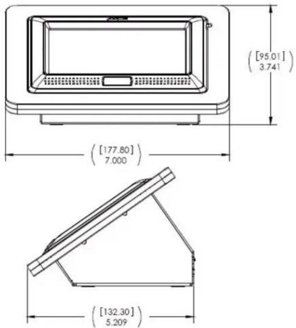
FIG. 7 Enclosure Dimensions - NXA-TTS43X-BL and NXA-TTS500-BL
MET-TTS1/2/3-BL and AP-TTS16-BL
The MET-TTS1/2/3-BL and AP-TTS16-BL share the same TTS enclosure (FIG. 5):
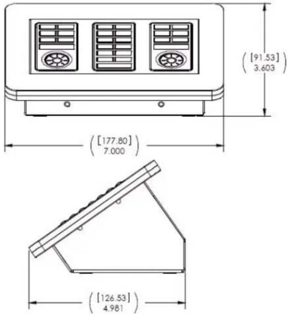
FIG. 8 Enclosure Dimensions - MET-TTS123-BL and AP-TTS16-BL
Additional Documentation
Refer to the Installation Guide specific to the TTS Table-Top Stand that you are installing for detailed instructions on installing the Touch Panel, Keypad(s) or ControlPad into the TTS Enclosure:
• AP-TTS16-BL Installation Guide
• MET-TTS123-BL Installation Guide
• NXA-TTS43X-BL Installation Guide
• NXA-TTS500-BL Installation Guide
Brand : AMX
Model : NXA-TTS43X
Category : Flat Screen Mount