
100013265 - Multimedia NEC - Free user manual and instructions
Find the device manual for free 100013265 NEC in PDF.


| Product Type | Multimedia Projector |
| Brand | NEC |
| Model | 100013265 |
| Display Technology | DLP |
| Resolution | 1920 x 1080 (Full HD) |
| Brightness | 3500 ANSI Lumens |
| Contrast Ratio | 10000:1 |
| Lamp Life | Up to 5000 hours (Eco Mode) |
| Projection Size | 30 - 300 inches |
| Keystone Correction | Vertical ±40° |
| Inputs | HDMI, VGA, USB, Composite Video |
| Audio Output | Built-in 10W Speaker |
| Dimensions (W x D x H) | 315 x 245 x 115 mm |
| Weight | 3.2 kg |
| Power Consumption | 260W (Normal), 0.5W (Standby) |
| Power Supply | AC 100-240V, 50/60Hz |
| Operating Temperature | 5°C to 40°C |
| Cleaning Instructions | Wipe with a soft, dry cloth. Do not use liquid cleaners. |
| Safety Features | Auto-off, overheat protection |
| Spare Parts Availability | Lamp and filter available through NEC service centers |
| Warranty | 2 years limited |
Frequently Asked Questions - 100013265 NEC
User questions about 100013265 NEC
0 question about this device. Answer the ones you know or ask your own.
Ask a new question about this device
Download the instructions for your Multimedia in PDF format for free! Find your manual 100013265 - NEC and take your electronic device back in hand. On this page are published all the documents necessary for the use of your device. 100013265 by NEC.
USER MANUAL 100013265 NEC
Installation and Assembly: 3 x 3 Cart
Model: DS-VWC655-3x3

natural_image
Isometric diagram of a modular storage unit with wheels and panel panels, no text or symbols presentMaximum Load Capacity 1000 lbs (454 kg)
PARTS LIST
| Description Qty. Part # | |
| A vertical support 2 145-1543 | |
| B adapter brackets 18 145-1711 | |
| C horizontal support | 3 145-1382 |
| D shelf | 1 145-1361 |
| E 5" caster | 4 600-0026 |
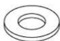
| F 1/4" flat washer | 48 540-9440 |
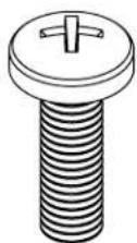
| G M8 x 25 mm phillips screw | 16 520-1031 |
| H 5/16 flat washer | 16 540-9406 |
| I 5/16 split washer | 16 540-9405 |
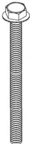
| J 1/4-20 x 3.5" hex head screw | 48 520-1656 |
| K 1/4-20 nylock nut | 48 530-9413 |
| L .38 OD x .06 LG nylon washer | 36 590-2233 |
| M 18" mesh sleeve | 9 600-1014 |
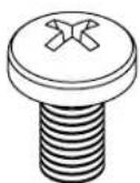
| N M8 x 16 mm phillips screw | 36 520-9257 |
| O M6 x 12 mm phillips screw | 36 520-1128 |
| P 4 mm allen wrench | 9 560-9646 |
| Q cable tie | 18 560-9711 |
| R tube cap | 2 590-1289 |
| S M5 x 10 mm socket pin screw (not used) | 18 520-1164 |
| T #14 fender washer (not used) | 36 540-1008 |
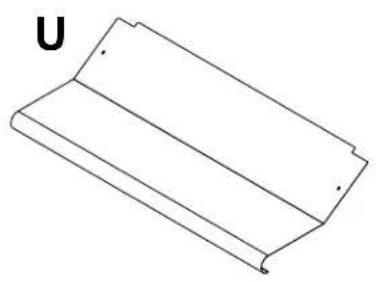
| U lower front cover | 1 145-1505 |
| V lower back cover | 1 145-1384 |
| W upper cover | 2 145-1450 |
| X rail connection bracket | 6 145-1503 |
| Y horizontal rail | 6 145-1447 |
| Z side cover | 2 145-1362 |
| AA M5 x 10 mm phillips screw | 40 520-1233 |
| BB flat washer | 40 540-9400 |
| CC lock washer | 40 540-1035 |
| DD decorative screw | 14 520-2326 |
| EE spacer | 4 590-1136 |
| FF self-drilling screw | 3 520-1320 |
| GG connection bracket | 4 145-1504 |
| HH M6 x 16 mm phillips screw | 36 520-9274 |

natural_image
Technical line drawing of a mechanical support structure with labeled section A (no text or symbols on the diagram itself)B

natural_image
Technical line drawing of a mechanical assembly with no visible text or symbolsC

natural_image
Simple line drawing of a vertical pole with two flanking square bases (no text or symbols)G
D

natural_image
Simple 3D diagram of a rectangular prism with dashed internal lines, labeled 'D' in the top-left corner (no text or symbols on the diagram itself)E

H

|

F
J
natural_image
Illustration of a hexagonal bolt with threaded shaft (no text or symbols)K

L

M

Q

natural_image
Simple line drawing of a straight rod with a small square end (no text or symbols)NOP


natural_image
Isometric line drawing of a layered rectangular object with a square top and rounded base (no text or symbols)S

T

natural_image
Simple line drawing of a folded or layered object with no text, numbers, or symbols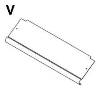
natural_image
Simple line drawing of a rectangular object with a label 'V' at the top (no other text or symbols)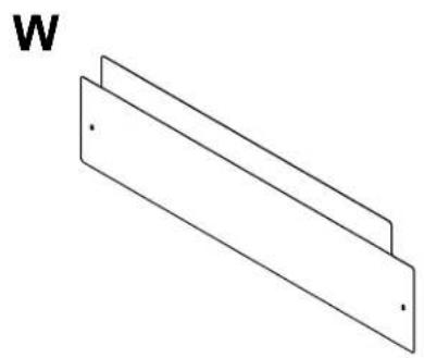
natural_image
Simple line drawing of two parallel plates with a label 'W' (no text or symbols on the plates themselves)X

Y

natural_image
Simple line drawing of a vertical rectangular object with rounded ends and no visible text or symbols
natural_image
Simple geometric shape with a labeled point 'Z' and two dots on either side (no text or symbols beyond the label)AA BB CC


GG

DD EE FF


Assembling Cart
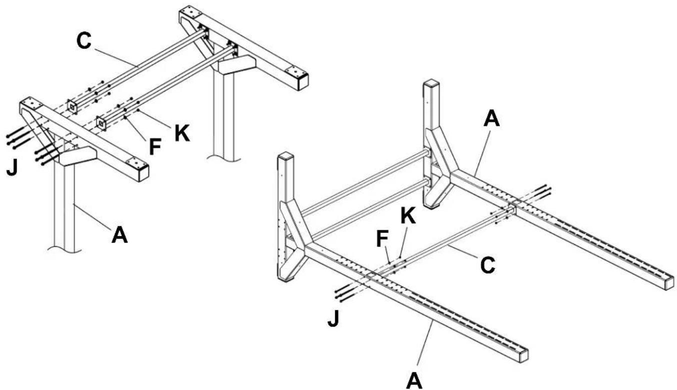
1 Attach two horizontal supports (C) to vertical support (A) using eight 1/4-20 x 3.5" hex head screws (J), 1/4" SAE washers (F) and 1/4-20 nylock nuts (K).

2 Attach horizontal supports (C) to second vertical support (A) using eight 1/4-20 x 3.5" hex head screws (J), 1/4" SAE washers (F) and 1/4-20 nylock nuts (K).
3 Attach horizontal support (C) to vertical supports (A) using eight 1/4-20 x 3.5" hex head screws (J), 1/4" SAE washers (F) and 1/4-20 nylock nuts (K).

Attach four swivel casters (E) to vertical supports (A) using sixteen M8 x 25 mm pan phillips screws (G), split washers (I) and 5/16" SAE flat washers (H).


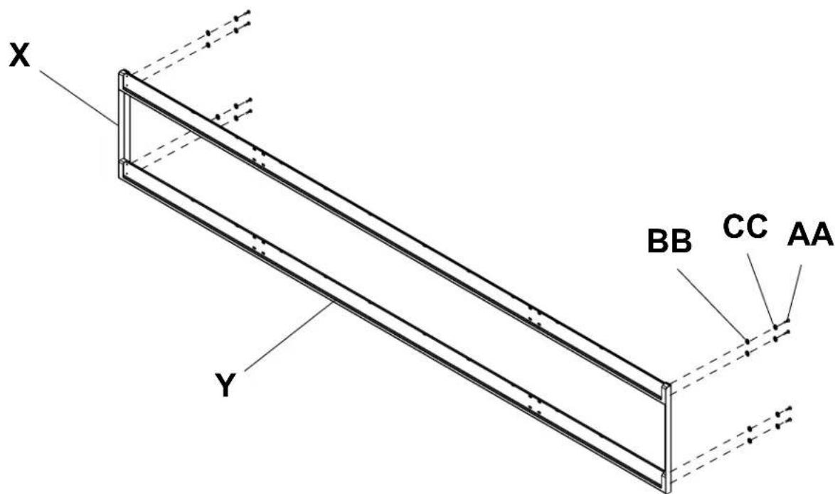
Attach two rail brackets (Y) together using two rail connection brackets (X) with eight M5 x 10 mm pan phillips screws (AA), lock washers (CC), and flat washers (BB).

Determine position of horizontal rails assemblies using the formula below.
- Locate the position of the lower horizontal rail assemblies and attach to vertical supports (A).
- Use display height to determine location of upper horizontal rail assemblies,
NOTE: Horizontal rail assemblies must be secured using twenty-four 1/4-20 x 3.5" hex head screws (J).
X = HEIGHT OF DISPLAY
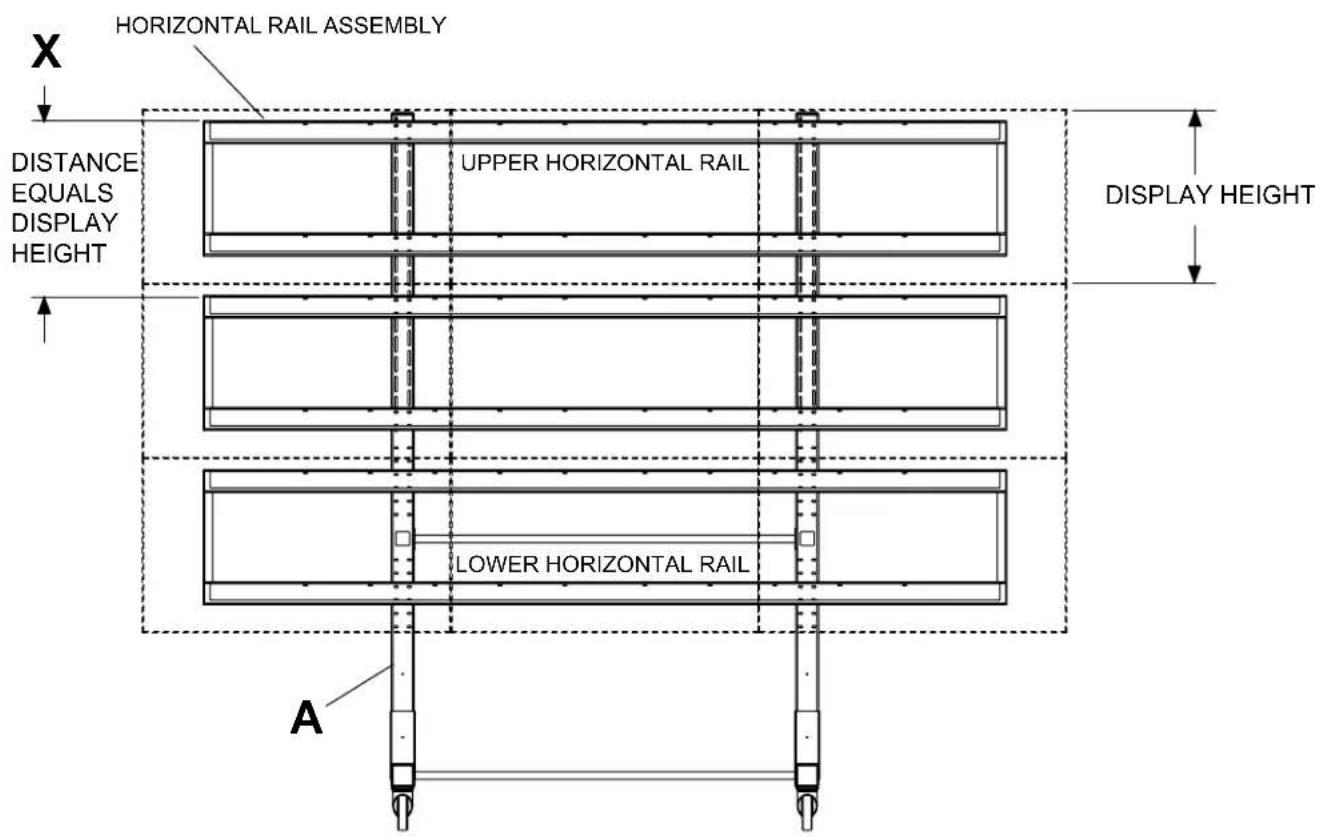

Attach three horizontal rails assemblies onto vertical supports (A) using twenty-four 1/4-20 x 3.5" hex head screws (J), 1/4" SAE washers (F) and 1/4-20 nylock nuts (K) as shown in detail 2. Make sure that horizontal rail assemblies are level then tighten all 1/4-20 x 3.5" hex head screws (J). Place two tube caps (R) into tops of vertical supports (A) as shown in detail 2. NOTE: horizontal rails must be secured using twenty-four 1/4-20 x 3.5" hex head screws (J).

CABLE MANAGEMENT

Run display cables though top and bottom openings in vertical supports (A) as shown. NOTE: Display cables can be covered using 18" mesh sleeve (M) before securing.
Display cables can be secured to horizontal rails assemblies using cable ties (Q) as needed through slots in horizontal rails (Y).


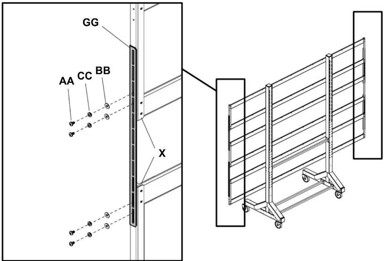
NOTE: Connection brackets (GG) orientation.
Place connection brackets (GG) onto rail connection brackets (X) as shown below.


Attach connection brackets (GG) onto rail connection brackets (X) as shown below.
Secure one connection brackets (GG) with four M5 x 10 mm phillips screws (AA), lock washers (CC), and flat washers (BB) as shown below. Repeat step for remaining three connection brackets (GG).
Attach adapter brackets (B) to back of display using four M6 x 12 mm phillips screws (O) or M6 x 16 mm Phillips screw (HH) with nylon shoulder washer (L), or four M8 x 15 mm phillips screws (N) as shown below.


Hook display and adapter brackets (B) onto horizontal rail assemblies as shown below.
NOTE: Start with bottom display.
NOTE: Once display is located in desired position, tighten security screws as shown in detail 4. DISPLAY NOT SHOWN FOR CLARITY


Adapter Bracket Adjustment

Use legend below to determine position of display.
NOTE: Each knob can be adjusted independently for fine tuning angle adjustments.

Turn knobs CLOCKWISE to raise display height.
Turn knobs COUNTER-CLOCKWISE to lower display height.

Turn knobs CLOCKWISE to push out display.
Turn knob COUNTER-CLOCKWISE to pull in display.
UP DOWN IN OUT


natural_image
Technical line drawing of a mechanical component with mounting holes and mounting brackets (no text or symbols)
natural_image
Technical line drawing of a mechanical bracket with mounting holes and mounting flanges (no text or symbols)


natural_image
Mechanical assembly diagram showing a vertical cylindrical device with internal components and directional arrows indicating motion (no text or symbols)KNOB

natural_image
Mechanical assembly diagram showing rotational components and directional arrows (no text or labels)Attaching Covers

NOTE: Position bottom front and back covers first
Position front bottom cover (U). Secure covers in place using four decorative screws (DD) as shown below.
Position back bottom cover (V). Secure covers in place using four decorative screws (DD) as shown below.
Position upper cover (W) on front of vertical supports (A). Secure covers in place using four decorative screws
(DD) as shown below. Position upper cover (W) on back of vertical supports (A). Secure covers in place using four decorative screws (DD) as shown below.


Attach two retaining spacers (EE), and decorative screws (DD) to side cover (Z) as shown to right. Attach side cover to vertical support (A) so that it goes inside the lower front and back covers (U and V).
Brand : NEC
Model : 100013265
Category : Multimedia