
PLP-91/D - Flat Screen Mount SONY - Free user manual and instructions
Find the device manual for free PLP-91/D SONY in PDF.


| Product Type | Flat Panel Wall Mount |
| Brand | Sony |
| Model | PLP-91/D |
| Category | Flat Panel Support |
| Compatible VESA Patterns | 100x100 mm to 400x400 mm |
| Maximum Screen Size | Up to 55 inches |
| Maximum Weight Capacity | 35 kg (77 lb) |
| Tilt Range | -15° to +15° |
| Swivel Range | -90° to +90° |
| Level Adjustment | ±4° |
| Distance from Wall | 60 mm to 500 mm |
| Material | Steel, Plastic |
| Color | Black |
| Included Hardware | Mount brackets, screws, wall anchors, spacers, screw kit |
| Installation Type | Wall mount with dual studs |
| Warranty | 2 years |
| Dimensions (WxHxD) | 500 x 200 x 60 mm (min) |
| Weight | 3.2 kg (7 lb) |
| Package Contents | Wall plate, TV bracket, screws, manual |
| Certifications | VESA compliant, TÜV certified |
Frequently Asked Questions - PLP-91/D SONY
User questions about PLP-91/D SONY
0 question about this device. Answer the ones you know or ask your own.
Ask a new question about this device
Download the instructions for your Flat Screen Mount in PDF format for free! Find your manual PLP-91/D - SONY and take your electronic device back in hand. On this page are published all the documents necessary for the use of your device. PLP-91/D by SONY.
USER MANUAL PLP-91/D SONY
Universal Pitch-Adjustable Wall Mount For Flat Panel Display PLP-91/D
Your new Wall Mount (PLP-91/D) is a quick disconnect mounting system with adjustability between 0 and 15 degrees pitch. The optional lateral shift bracket (PAC-125) allows 4" lateral shift on either side of a 16" center stud or spans a 24" on center stud system.
Once the Universal Flat Panel Display Wall Mount Bracket is attached to your display, simply attach the mount securely on a wall, lock the display in place using the convenient Q-latch, and attach your audio/video cables.
The PLP-91/D is virtually invisible when your display is mounted.
BEFORE YOU BEGIN
- Caution: To prevent damage to the PLP-91/D, which could affect or void the Factory warranty, and to the equipment that will be attached to it, thoroughly study all instructions and illustrations before you begin the installation. Pay particular attention to the “Important Warnings and Precautions” on Page 1.
- The mount is designed to be installed using wall studs or supporting framework. The fasteners used to anchor the mount must be capable of supporting five times the total weight of the equipment.
- The maximum weight to be installed on the Universal Pitch-Adjustable Wall Mount is 125 pounds (56.7 Kg).

IMPORTANT WARNINGS AND PRECAUTIONS!
WARNING: A WARNING alerts you to the possibility of serious injury or death if you do not follow the instructions.
CAUTION: A CAUTION alerts you to the possibility of damage or destruction of equipment if you do not follow the corresponding instructions.
- WARNING: Improper installation can result in serious personal injury! Make sure that the structural members can support a weight factor five times the total weight of the equipment. If not, reinforce the structure before installing the mount.
- WARNING: Be aware also of the potential for personal injury or damage to the unit if it is not adequately mounted.
- WARNING: The installer is responsible for verifying that the wall to which the mount is anchored will safely support the combined load of all attached components or other equipment.
- WARNING: Watch for pinch points. Do not put your fingers between movable parts.
- WARNING: Make sure the mount and brackets are correctly oriented.
- WARNING: Make sure the latching flag securing the display is completely engaged at all times except when removing or installing the display. The latching flag must be all completely engaged when installing/removing cables.
- CAUTION: Check the unit for shipping damage before you begin the installation.
- CAUTION: Use only the mounting screws provided and DO NOT OVER TIGHTEN mounting screws.
CONTENTS
DIMENSIONAL DRAWING 2
INSTALL MOUNT.... 3
INSTALL DISPLAY BRACKETS.... 3
MOUNT THE DISPLAY.... 3
PARTS 4
TOOLS REQUIRED FOR INSTALLATION
• Phillips screwdrivers, No. 1 and No. 2 TIP
- Drill and bit set
- Wrench set
NOTE: Other tools may be required depending on the method of installation.
INTERFACE BRACKETS ADD APPROXIMATELY 1/2" TO DEPTH
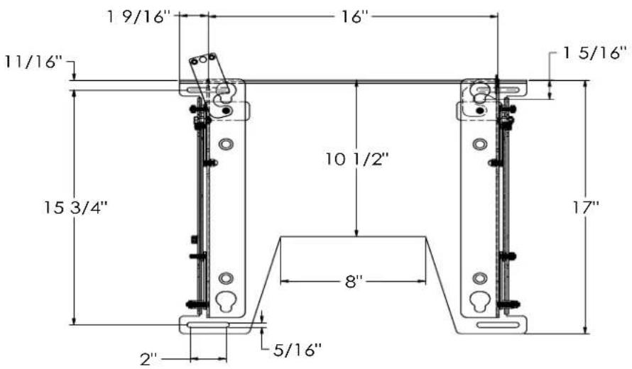
DIMENSIONAL DRAWING
INSTALL MOUNT
Install the mount as follows:
- Determine the exact mounting location prior to installation and draw a level line to indicate the desired height for the top of the mounting plate.
WARNING: Improper installation can result in serious personal injury! Make sure that the structural framework can support a weight factor five times the total weight of the equipment. If not, reinforce the structure before installing the mount.
-
With the mount correctly oriented and level, secure the mount to the wall (see Figure 1) using four fasteners (not included). Fasteners must be driven into the supporting wall studs or other supporting framework.
-
Check mount to ensure it is level and adjust to level if necessary.
INSTALL DISPLAY BRACKETS
Install display bracket(s) according to the instructions provided. The bracket(s) is/are designed for your specific model.
MOUNT THE DISPLAY
Mount the display as follows:
-
Make sure no power is supplied to the display and the flags are in the lowered (open) position before attempting to mount the display.
-
Using two people, slide the display down over the mount. Make sure all four Q-buttons of the display engage all four slots in the mount.
-
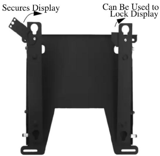
With the Q-buttons of the display fully engaged in the slots of the mount, secure the display on the mount by raising the flags all the way to their locked position. If the flags do not fully engage, remove the display and make sure the brackets are correctly installed.
NOTE: A security lock may be installed through the hole in the locking flag for additional security (see Figure 2).
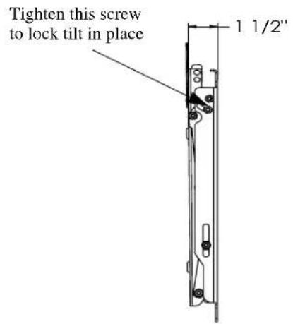
NOTE: If display does not remain at desired tilt setting, tighten the nut and bolt on tilt arms on each side (see Figure 3).
WARNING: Make sure the flag securing the display is completely lowered at all times except when removing or installing the display. The flag must be all the way down when installing/removing cables.
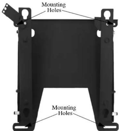
Figure 1. Mounting Hole Locations
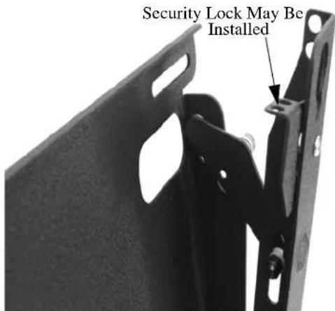
Figure 2. Optional Security
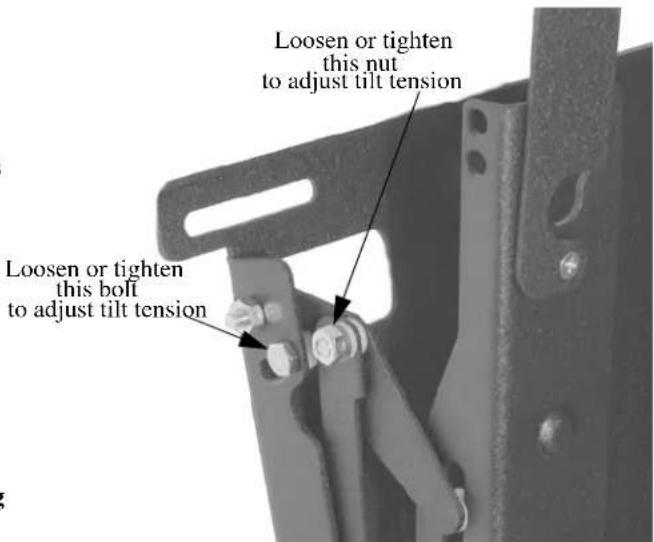
Figure 3. Tilt Tension Adjustment
PARTS
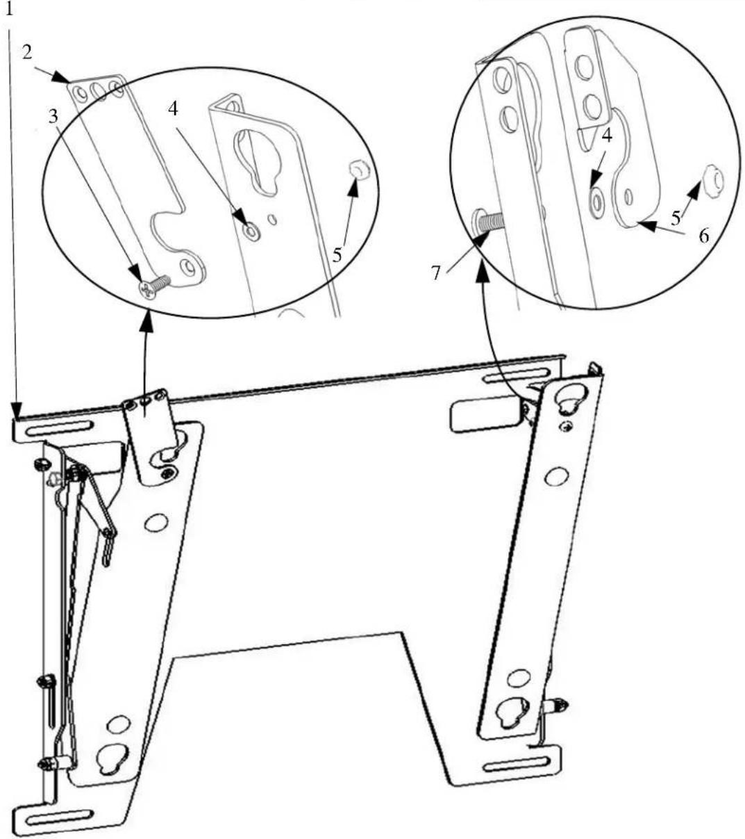
Table 1: Parts
| Ref D | Description Qty Ref Description Qty | |||||
| 1 MOUNT 1 5 NUT, Nylock, 10-24 2 | ||||||
| 2 FLAG, Extended 1 6 FLAG, Locking 1 | ||||||
| 3 SCREW, 10-24X1/2, FH 1 7 SCREW, 10-24X1/2, Phillips | 1 | |||||
| 4 WASHER, Nylon 2 | ||||||
INSTALLATION INSTRUCTIONS
PSB-91/D
PLASMA DISPLAY MOUNTING BRACKET
Prior to assembly, unpack carton completely and verify contents.
If you are missing any of the following components, please contact Customer Service at 1-800/582-6480
natural_image
Pure electrical circuit lines without any symbolsFigure 1
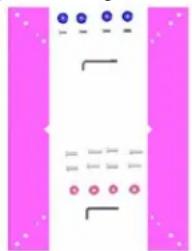
(2) Plasma Bracket (4) Mounting Buttons – Tapped
(4) 10-24 x ½ Button Head Cap Screw (1) 1/8 Allen Key
(4) M5 x 20mm Phillips Head Cap Screw (4).875 OD x .33 ID x .375 Nylon Spacer
(4) M6 x 20mm Button Head Cap Screw (1) M4 Allen Key
BEFORE PROCEEDING, READ INSTALLATION INSTRUCTIONS COMPLETELY
CAUTION!
PLASMA DISPLAYS ARE EXTREMELY FRAGILE.
WARNING!
ALL COMPONENTS MUST BE SECURELY FASTENED TO A STRUCTURAL MEMBER CAPABLE OF SUPPORTING 4TIMES THE COMBINED WEIGHT OF ALL COMPONENTS PLUS THE EQUIPMENT BEING MOUNTED. IF IT CANNOT SUPPORT THIS WEIGHT, THE STRUCTURE MUST BE REINFORCED.
THE MAXIMUM WEIGHT TO BE INSTALLED ON THE MOUNT IS 125 POUNDS (56.7 KG).
- Using a 10-24 button head cap screw inserted from back side of bracket, secure mounting button, with chamfered hole of mounting button (larger surface) facing bracket, to bracket (four places) (see
Figure 2 & Figure 3).
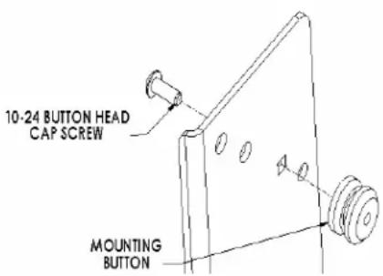
Figure 2
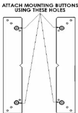
Figure 3
- Place Nylon spacers over mounting holes on back of screen.
- Attach mounting brackets to the display using the M5 screws for 32" screen or M6 for 42" and 50" screens (see Figure 4 & Figure 5).
- With the aid of another person, lift your display up to the mount, aligning buttons of mounting brackets with slots in the mount.
- Lower safety catch on the mount to secure your display, making sure latch is completely engaged.
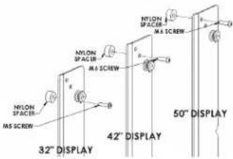
Figure 4
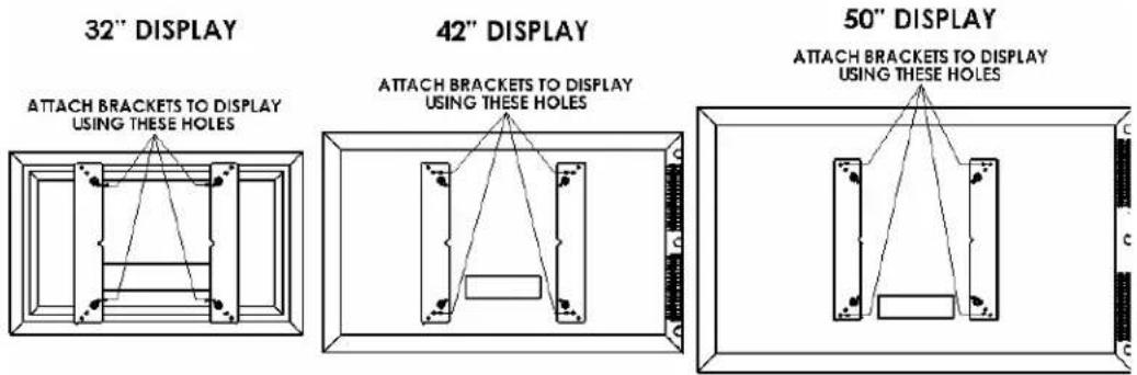
Figure 5
- Universal Pitch-Adjustable Wall Mount For Flat Panel Display PLP-91/D
- BEFORE YOU BEGIN
- IMPORTANT WARNINGS AND PRECAUTIONS!
- CONTENTS
- TOOLS REQUIRED FOR INSTALLATION
- INSTALL MOUNT
- INSTALL DISPLAY BRACKETS
- MOUNT THE DISPLAY
- PARTS
- INSTALLATION INSTRUCTIONS
- PSB-91/D
- PLASMA DISPLAY MOUNTING BRACKET
- CAUTION!
- WARNING!
Brand : SONY
Model : PLP-91/D
Category : Flat Screen Mount