MXNet AC-MXNET-1G-AVDM - NAS AVPro Edge - Free user manual and instructions
Find the device manual for free MXNet AC-MXNET-1G-AVDM AVPro Edge in PDF.


| Product Type | AV over IP Encoder with Audio Downmixing |
| Model | AC-MXNET-1G-AVDM |
| Brand | AVPro Edge |
| HDMI Input | 1x HDMI Type A female (4K60 4:4:4, 18Gbps) |
| HDMI Loop Out | 1x HDMI Type A female (supports EDID copy) |
| Audio Downmixing | Surround sound to stereo downmixing with 7 preset modes |
| Network Interface | 1x RJ-45 1000BASE-T (PoE) |
| SFP Port | 1x Bi-directional LC fiber (supports single/multimode) |
| PoE Support | IEEE 802.3af (15.4W) – PoE powered |
| Power Consumption | 9.5W (typical) |
| Power Supply Options | PoE or DC 12V/1A (locking ring, optional) |
| USB Ports | 1x USB 2.0 Type B (host), 1x micro-USB (service) |
| RS-232 Control | 1x 3-pin terminal block (virtualized over IP) |
| IR Control | 1x IR In (3.5mm), 1x IR Out (3.5mm), 1x I-PASS (3.5mm) |
| Analog Audio Input | 1x 3.5mm stereo jack (overrides HDMI audio) |
| Balanced Audio Output | 1x 5-pin terminal block (de-embedded 2ch PCM) |
| Maximum Resolution | 4K60 4:4:4 (10/12-bit HDR) |
| Dimensions (approx.) | 170mm x 100mm x 25mm (without connectors) |
| Weight (approx.) | 0.4 kg |
| Operating Temperature | 0°C to 40°C (32°F to 104°F) |
| Humidity | 10% to 90% non-condensing |
| Warranty | 10 years (limited, see manual for details) |
| Maintenance | Clean with dry cloth; do not use liquids |
| Safety | Electrical shock prevention; use dry environment |
| Spare Parts & Repairability | Contact AVPro Edge for service; no user-serviceable parts |
Frequently Asked Questions - MXNet AC-MXNET-1G-AVDM AVPro Edge
User questions about MXNet AC-MXNET-1G-AVDM AVPro Edge
0 question about this device. Answer the ones you know or ask your own.
Ask a new question about this device
Download the instructions for your NAS in PDF format for free! Find your manual MXNet AC-MXNET-1G-AVDM - AVPro Edge and take your electronic device back in hand. On this page are published all the documents necessary for the use of your device. MXNet AC-MXNET-1G-AVDM by AVPro Edge.
USER MANUAL MXNet AC-MXNET-1G-AVDM AVPro Edge
Important Safety Instructions....6
1 Introduction 8
1.1 Descriptions 8
1.1.1 Encoders and Decoders....8
1.1.1.1 MXNet 1G Evolution II....8
1.1.1.2 Audio Downmixing....9
1.1.2 Control 9
1.1.3 Mentor 9
1.1.4 Network Switches....9
1.2 Before You Begin 10
1.3 Some Helpful Suggestions....10
1.4 Network Cabling Tips....10
1.5 Recommended Best Practices.... 11
1.6 Third-Party Control Systems....11
2 Third-Party Network Switch Requirements....12
2.1 IGMPv2 Snooping 12
2.2 IGMPv2 Querier 12
2.3 IGMPv2 Immediate-Leave 12
2.4 Unknown Multicast Dropping (or Unregistered Multicast Flooding)....12
2.5 MTU Settings 12
2.6 PoE Budget....13
2.7 Disabling EEE....13
3 Product Overview....14
3.1 Box Contents and Specifications....14
3.2 AC-MXNET-1G-E / AC-MXNET-1G-E-AVDM / AC-MXNET-1G-EV2.... 14
3.3 AC-MXNET-1G-EWP 17
3.4 AC-MXNET-1G-D / AC-MXNET-1G-DV2 19
3.5 AC-MXNET-CBOX....21
3.6 AC-MXNET-SW10 23
3.7 AC-MXNET-SW24....24
3.8 AC-MXNET-SW48 26
4 Wiring and Connections....28
4.1 1G Ethernet/LAN....28
4.2 AV NETWORK....28
4.3 SFP and SFP+ Transceiver Modules....29
4.3.1 Compatible SFP and SFP+ Transceiver Modules Specifications for MXNet Network Switches .... 30
4.3.2 Installing SFP and SFP+ Transceiver Modules.... 30
4.3.3 Short Reach (SR) SFP or Long Reach (LR) SFP 31
4.4 DAC Cables 31
4.5 HDMI Cables....31
4.6 USB Ports....31
4.7 RS-232 Wiring....32
4.8 IR Wiring 32
4.9 Analog Audio Ports 32
4.10 AC Power Connection....32
5 Installation....33
5.1 Connecting the Devices....33
5.2 Point-to-Point Setup 35
5.2.1 Configuring Encoders and Decoders....35
5.3 Stacking Switches.... 38
5.3.1 Stacking Two AC-MXNET-SW24 38
5.3.2 Stacking Two AC-MXNET-SW48 38
6 The Mentor Web UI 39
6.1 Accessing Mentor....39
6.2 Navigating the Mentor Web UI 40
6.3 System Utilities....41
6.3.1 LAN and AV Network Configurations 41
6.3.2 MXNet Firmware Updates....41
6.3.3 MXNet Events 42
6.4 Configure Inputs and Outputs....43
6.4.1 Inputs/Encoders/Sources 44
6.4.2 Outputs/Decoders/Displays 45
6.4.3 Encoder Module (AVDM Encoders only) 47
6.4.4 System Diagnostics....48
6.9 Auto-Matrix 50
6.9.1 Inputs 50
6.9.2 Outputs 50
6.9.3 Matrix Switching....51
6.9.4 Matrix Presets .... 51
6.9.5 Creating a Preset....51
6.9.6 Activating a Preset....52
6.9.7 Deleting a Preset....52
6.10 Video Wall....53
6.10.1 Standard Layout....53
6.10.2 Mosaic-Style Layout....53
6.10.3 Creating a Video Wall Array....53
6.10.4 Creating a Mosaic Video Wall....56
6.10.5 Creating Another Layout....61
6.11 Central Command 63
6.11.1 Creating a CEC Control Configuration....63
6.11.2 Creating an RS-232 Control Configuration....64
6.11.3 Creating an IR Control Configuration....64
6.11.4 Routing Groups for Encoders and Decoders....64
6.12 Independent Routing 65
6.12.1 Creating a Routing Path....65
6.13 USB & KVM 66
6.13.1 Creating a USB or KVM Routing Path 67
6.14 KVM Roaming....68
6.14.1 Creating a KVM Array....68
6.15 Custom Images 71
6.15.1 Fallback Logo....71
6.15.2 Uploading a Fallback Logo or "No Signal" Image....72
6.15.3 Force Image....72
6.15.4 Uploading a Force Image....72
6.16 System Log 74
7 Maintenance 76
8 Damage Requiring Service....76
9 Support....76
10 Warranty....76
10.1 The Basics....76
10.2 Coverage Details....77
10.3 Red Tape....77
10.4 Obtaining an RMA....77
10.5 Shipping....77
10.6 Limitation on Liability 78
10.7 Exclusive Remedy 78
IMPORTANT SAFETY INSTRUCTIONS
Prior to installing, configuring, and operating all MXNet devices and other vendor equipment, AVPro Edge recommends that each dealer, integrator, installer, and all other necessary personnel access and read all the required technical documentation, which can be located by visiting AVProEdge.com.
Read and understand all safety instructions, cautions, and warnings in this document and the labels on the equipment.
Safety Classifications in this Document
| NOTE: | Provides special information for installing, configuring, and operating the devices. |
| TIP: | Provides suggestions and considerations for installing, configuring, and operating the devices. |
| IMPORTANT: | Provides special information that is critical for installing, configuring, and operating the equipment. |
| CAUTION: | Provides special information for avoiding situations that may cause damage to the devices. |
| WARNING: | Provides special information for avoiding situations that may cause physical danger to the installer, end user, etc. |
| NOTE: | Provides special information for installing, configuring, and operating the devices. |
| TIP: | Provides suggestions and considerations for installing, configuring, and operating the devices. |
| IMPORTANT: | Provides special information that is critical for installing, configuring, and operating the equipment. |
| CAUTION: | Provides special information for avoiding situations that may cause damage to the devices. |
| WARNING: | Provides special information for avoiding situations that may cause physical danger to the installer, end user, etc. |
Electrical Shock Prevention

ELECTRICAL SHOCK:
The source power poses an electrical shock hazard that can potentially cause serious injury to installers and end users.

ELECTRICAL DISCONNECT:
The source power outlet and power supply input power sockets should be easily accessible to disconnect power in the event of an electrical hazard or malfunction.
Weight Injury Prevention
WEIGHT INJURY:
Installing some of the MXNet devices requires two installers to ensure safe handling during installation. Failure to use two installers may result in injury.
Safety Statements
Follow all of the safety instructions listed below and apply them accordingly. Additional safety information will be included where applicable.
- Read and keep these instructions.
- Heed all warnings and follow all instructions.
- Do not use these devices near water.
- Clean only with a dry cloth.
- Do not block any ventilation openings. Install in accordance with the manufacturer's instructions.
-
Do not install near any heat sources such as radiators, heat registers, stoves, or other apparatus (including amplifiers) that produce heat.
-
Do not defeat the safety purpose of the polarized or grounding-type plug. A polarized plug has two blades with one wider than the other. A grounding-type plug has two blades and a third grounding prong. The wide blade or third prong are provided for your safety. If the provided plug does not fit into your outlet, consult an electrician for replacement of the obsolete outlet.
-
Protect the power cord from being walked on or pinched particularly at plugs, convenience receptacles, and the point where they exit from the devices.
-
Only use attachments and accessories specified by the manufacturer.
-
Unplug these devices during lightning storms or when unused for long periods of time.
-
To reduce the risk of electric shock or damage to these devices, never handle or touch the devices and power cord if your hands are wet or damp. Do not expose these devices to rain or moisture.
-
Refer all servicing to qualified service personnel. Servicing is required when the devices have been damaged in any way, such as power supply cord or plug is damaged, liquid has been spilled, objects have fallen into the devices, the devices have been exposed to rain or moisture, does not operate normally as intended, or has been dropped.
-
The devices and their accessories should never be exposed to open flames or excessive heat.
1 INTRODUCTION
The MXNet 1G Ecosystem is an AV over IP platform of products that uses standard networking infrastructure to route video, audio, and control signals throughout large scale systems with an unlimited number of sources and displays, all switching independently and seamlessly. Designed and developed by AVPro Edge to be truly “plug and play”, MXNet provides the complete end-to-end solution for stability, interoperability, and easy deployment of the entire system.
The diagram below shows the basic application with the AC-MXNET-SW48 network switch, AC-MXNET-1G-E encoders, AC-MXNET-1G-D decoders, and AC-MXNET-CBOX.
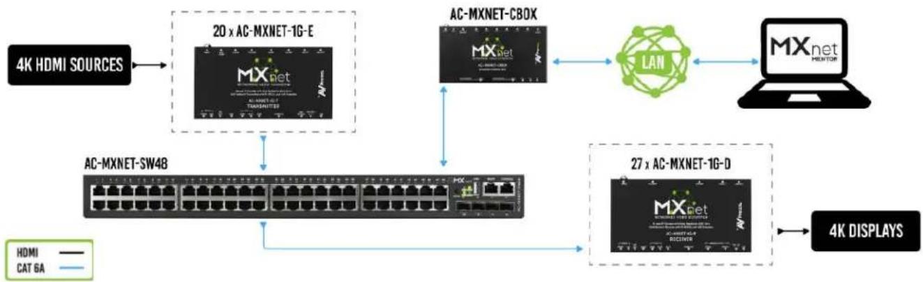
flowchart
graph TD
    A["4K HDMI SOURCES"] --> B["20 x AC-MXNET-1G-E"]
    B --> C["AC-MXNET-SW48"]
    C --> D["27 x AC-MXNET-1G-D"]
    D --> E["4K DISPLAYS"]
    F["AC-MXNET-CBOX"] --> G["LAN"]
    G --> H["MXnet MENION"]
    H --> I["Computer"]
    style A fill:#f9f,stroke:#333
    style B fill:#ccf,stroke:#333
    style C fill:#cfc,stroke:#333
    style D fill:#fcc,stroke:#333
    style E fill:#ffc,stroke:#333
    style F fill:#fcc,stroke:#333
    style G fill:#cff,stroke:#333
    style H fill:#ffc,stroke:#333
    style I fill:#fcc,stroke:#333
1.1 Descriptions
1.1.1 Encoders and Decoders
The AC-MXNET-1G-E, AC-MXNET-1G-EV2, AC-MXNET-1G-E-AVDM, AC-MXNET-1G-EWP, AC-MXNET-1G-DV2, and AC-MXNET-1G-D are all 1GbE encoder/decoder endpoint devices that extend HDMI video, audio, USB 2.0, and control signals from a local source to a remote sink display or output device. The encoders and decoders connect directly to an MXNet network switch, or other compatible switch, via a Category cable or SFP fiber optic connection. The encoders also support standalone point-to-point applications (encoder to decoder with a direct Category cable connection). The encoders and decoders support both DHCP (factory default) and static IP address settings.
1.1.1.1 MXNet 1G Evolution II
The AC-MXNET-1G-EV2 and AC-MXNET-1G-DV2 incorporate a newly designed AVPro Edge application-specific integrated circuit (ASIC) that introduces an improved software-based video encoding/decoding engine into the IC for enhanced video processing. Refinements to the IC include full support for 4K 60Hz 4:4:4 signals (RGB and YCbCr at 10- and 12-bit color) with minimal compression, plus extended audio capabilities to support high bitrate multichannel formats, including Dolby Atmos and DTS:X for IMAX Enhanced soundtracks. All MXNet first-generation encoder features are retained for use with the AC-MXNET-1G-EV2.

IMPORTANT:
The AC-MXNET-1G-EV2 and AC-MXNET-1G-DV2 are EVO II ( 2^nd Evolution) devices and may coexist alongside MXNet first-evolution encoders and decoders within previously installed systems or pending system deployments. However, they are required to be used exclusively in EVO II transmitter-to-EVO II decoder(s) pairings only. For example, you cannot route signals from a first-evolution encoder/decoder to a second-evolution encoder/decoder.
1.1.1.2 Audio Downmixing
The AC-MXNET-1G-E-AVDM encoder provides the same functionality as the AC-MXNET-1G-E encoder with the addition of surround sound to stereo downmixing.
1.1.2 Control
The AC-MXNET-CBOX is the control device to command the encoders and decoders, and is where the system logic is stored and the commands are processed. The API utilized by the MXNet Mentor web interface and third-party control systems are centralized to the CBOX to provide multipoint AV over IP distribution. The CBOX enables networked signal extension, distribution, and routing using the MXNet 1G encoders, decoders, and network switches.
1.1.3 Mentor
MXNet Mentor is AVPro Edge's proprietary HTML5-based setup and control web interface designed to eliminate many pain points associated with installing and configuring traditional networked AV systems. Mentor is an efficient setup solution that's easy to use and comes pre-installed on every CBOX.
1.1.4 Network Switches
The AC-MXNET-SW10, AC-MXNET-SW24, and AC-MXNET-SW48 are network switches that are pre-configured out-of-the-box for networked AV distribution and can be deployed on any industry standard IP network. The switches can be used on an existing enterprise IP network or on a physically separate parallel network (private network) to offload traffic, using the same network protocols, methods, and devices without having to combine video traffic with network data.
1.2 Before You Begin
MXNet does not require the encoders and decoders to be connected in any specific order on the network switch, meaning they can be placed on adjacent ports right next to each other and the system will function without issue. However, for best results (especially when managing highly complex systems with dozens of endpoints) a certain degree of design and planning is highly recommended and can save precious time when it comes to installing, testing, and implementing features on the system.
Read through this document in its entirety and ensure that the following required items are available:
☐ MXNet 1G Encoder (AC-MXNET-1G-E, AC-MXNET-1G-E-AVDM, AC-MXNET-1G-EWP, or AC-MXNET-1G-EV2)
☐ MXNet 1G Decoder (AC-MXNET-1G-D or AC-MXNET-1G-DV2)
☐ MXNet CBOX for control and Mentor web interface (AC-MXNET-CBOX)
☐ MXNet 1G Network Switch (AC-MXNET-SW10, AC-MXNET-SW24, or AC-MXNET-48) or one that meets MXNet requirements (see Third-Party Network Switch Requirements)
Source devices, displays, and any other devices that will be used in the system
1.3 Some Helpful Suggestions
- Make a list of all the devices in the system, including the sources and displays, model numbers and SKU's, MAC addresses and assigned IP addresses, along with any accessories such as rack equipment, power sources, cable types and lengths.
- Create a diagram or flow chart to indicate the starting and end points of the network cable runs, as well as any schematics, diagrams, and other supporting documentation for easy future reference.
- Label the connections in the rack to their corresponding endpoints or ports on the network switch.
- For larger projects, consider grouping the encoder cables next to each other on the network switch and likewise for the decoders.
1.4 Network Cabling Tips
Everything about a successful MXNet installation revolves around the network cabling itself. Keep in mind that the quality, distance, and handling of the cable can all affect the signal speed and data stream. Generally speaking, the higher the video resolution and the longer the run, the better the cabling should be.
When terminating network cables, do not untwist the wires unnecessarily. Make sure to not untwist more than 12 inch, preferably 14 inch. Wires are twisted for good reasons:
- Cancels out EMI (Electromagnetic Interference)
- Cancels out crosstalk from neighboring conductors
For most applications, Cat5e (or better) is recommended for MXNet.
1.5 Recommended Best Practices
- Terminate with standard RJ-45 connectors. Avoid using push-through or "EZ" type ends, as these have exposed copper wiring at the tips that can cause signal interference.
- Cable terminations should be consistent with T568A or T568B. Avoid mixing terminations such as going from T568A to T568B, and vice versa.
- Remove as little of the sheath as possible.
- Handle cables with care. If you need to pull, don't pull too hard as this may cause the wire pairs to untwist and can degrade cable performance.
- Use zip ties to neatly, but loosely, bundle the cable runs together to reduce tangling. Avoid tight zip ties, clamps, and staples.
- Stay organized, label each cable run on both ends to indicate the location of the inputs and outputs.
- Do not overbend cables. 14 inch cable ratio = 2" bend radius.
- Keep network cables away from power sources.
1.6 Third-Party Control Systems
MXNet supports third-party control systems with drivers readily available to download, allowing for further customizable programming and commands to integrate with MXNet. Be sure to successfully install and connect your MXNet system to the network first before integrating it with a third-party control system.
Supported drivers for third-party control system can be located at Support.AVProEdge.com
2 THIRD-PARTY NETWORK SWITCH REQUIREMENTS
Third-party (non-AVPro or MXNet) network switches must support the following features and functionalities and enable or disable some settings in order to support the AVPro MXNet AV over IP system.
Verify that your third-party network switch has all of the following requirements for running MXNet:
- IGMP Version 2 for snooping, queries, Immediate-Leave, and unknown multicast data dropping
• MTU Size to support jumbo Ethernet frames
• PoE Budget to power the MXNet endpoint devices - Disable EEE functionality for system optimization
2.1 IGMPv2 Snooping
IGMP snooping is a method that network switches use to identify multicast groups, which are groups of devices (decoders) that all receive the same network traffic, such as video, audio, and control streams. It enables the switches to forward IP packets to the correct devices (decoders) in their network.
2.2 IGMPv2 Querier
The IGMP querier is responsible for sending out IGMP group membership queries at a timed interval, retrieving IGMP membership reports from active members, and allowing updates to the IGMP group tables.
2.3 IGMPv2 Immediate-Leave
When Immediate-Leave is enabled, the device immediately removes a port when it detects the IGMPv2 Leave message on that port. Immediate-Leave is only supported on IGMPv2 hosts and should be enabled for every port on the VLAN.
2.4 Unknown Multicast Dropping (or Unregistered Multicast Flooding)
Unknown multicast data refers to multicast data for which no forwarding entries exist in the IGMP snooping forwarding table. This feature enables the device to forward unknown multicast data to the router port only. If the device does not have a router port, unknown multicast data will then be dropped.
If this feature is not enabled, the unknown multicast data will flood the VLAN to which the data belongs and may severely interfere with normal network operations.
2.5 MTU Settings
The MTU (Maximum Transmission Unit) size needs to be changed to over 9000 bytes to support jumbo Ethernet frames on the AVPro MXNet AV over IP Ecosystem.
The MTU is the maximum payload length for a particular transmission media and is typically 1500 bytes.
A jumbo frame is an Ethernet frame with a payload greater than the standard MTU of 1500 bytes. Jumbo frames are used on LANs that support at least 1Gbps and can be as large as 9000 bytes, or even bigger. Since jumbo frames are not defined in the IEEE 802.3 specifications for Ethernet, vendor support for jumbo frames and their maximum MTU sizes may vary.
Jumbo frames provide a large number of benefits over the traditional IEEE 802.3 Ethernet MTU's. These include:
• The amount of frames sent across the network is reduced
- The number of Ethernet headers is reduced as a result of fewer frames.
- The reduction in frames results in fewer required headers.
- The CPU cycles are reduced at the sender and receiver side due to fewer headers needing to be built and read.
• Network bandwidth is reduced due to the reduction in headers.
2.6 PoE Budget
PoE network switches will power the MXNet endpoint devices (encoders and decoders), as each endpoint device consumes 6 to 9 Watts of power. Be sure to correctly identify the PoE budget of the third-party network switch before purchasing.
Example: a 24-port switch with a PoE budget of 370 Watts can supply up to 15.4 Watts of power per port on all 24 ports, meaning you can connect 24 MXNet endpoint devices on the 24-port switch. Likewise, a 48-port switch with a PoE budget of 740 Watts can power up to 48 MXNet endpoint devices.
2.7 Disabling EEE
EEE (Energy Efficient Ethernet) is an IEEE 802.3az standard that is designed to reduce power consumption in Ethernet networks during idle periods.
If the third-party network switch supports EEE, be sure to disable the EEE function as it may cause issues with system optimization in some cases.
3 PRODUCT OVERVIEW
3.1 Box Contents and Specifications
Refer to the Specifications page for these products located on the AVPro Edge Website for box contents and technical specifications.
3.2 AC-MXNET-1G-E / AC-MXNET-1G-E-AVDM / AC-MXNET-1G-EV2
Encoder Front Panel

Encoder Rear Panel

| 1 | POWERSTATUS | Blue LED status indicator lightSlowly pulsates until startup is complete after a reboot, at which point the light will turn solid blue |
| 2 | LINK STATUS | Green LED status indicator lightContinuously flashes until an active source is connected to the HDMI IN port on the encoder, or the source itself becomes active and is routed to a decoder, at which point the light will turn solid green |
| 3 | EDID COPY | Press to copy the EDID of the sink device connected to the HDMI LOOP OUT port on the back of the encoder |
| 4 | RS232 | 3-pin terminal block connector portSends encapsulated/virtualized RS-232 (serial pass-through) over IP via the MXNet APISupports serial routing with direct connection to a control system processor |
| 5 | I-PASS | 3.5mm stereo jack (TRS) IR receiver portSends IR signals via a direct connection from a control system processor to the IR output of the desired endpoint(s) |
| 6 | IR-EYE | 3.5mm stereo jack (TRS) IR receiver portSupports usage of an IR eye to capture IR signals from a control system processor or third-party remote to send IR signals to the IR output of the desired endpoint(s) |
| 7 | IR OUT | 3.5mm mono jack (TS) IR transmitter portSends encapsulated/virtualized IR signals upstream via the MXNET API |
| 8 | IP MONITOR | Built-in front panel mini-OLED screen "data window"Displays the encoder's custom name or MAC address and IP address |
| 9 | EDID SETTINGS | Dipswitches for manually setting an EDID on the encoder, can also be done in Mentor, either method will overwrite the previous setting[JUMPER 1234 FOLLOW SOFTWARE (default) 00001080P_2D_6CH 10001080P_3D_6CH 01001080P_3D_6CH 11004K30Hz_3D_2CH 00104K30Hz_3D_6CH 10104K30Hz_3D_8CH 01101080P_2D_2CH_HDR 11101080P_2D_6CH_HDR 00011080P_3D_2CH_HDR 10011080P_3D_6CH_HDR 01014K30Hz_3D_2CH_HDR 11014K30Hz_3D_6CH_HDR 00114K30Hz_3D_8CH_HDR 10111920x1200_3D_2CH_HDR 0111USER_EDID 1111 |
| 10 | USB SELECT | FPGA/MCU toggle switchUsed for configuring the encoder for point-to-point connection with an MXNet 1G decoder (default setting is MCU ISP) |
| 11 | USB | Micro-USB Type B female connector portUsed for configuring the encoder for point-to-point connection with an MXNet 1G decoder |
| 12 | GbENETWORK | 8-pin RJ-45 female connector, 1000BASE-T copper Ethernet portSupports standard PoE power, IEEE 802.3AF (15.4 W)Maximum power consumption of 6.5 W (AVDM 9.5 W)10/100/1000Mbps auto-negotiationMDI/MDI-X cable mode auto-negotiationMaximum distance 100m (330ft) over Cat5e and higher |
| 13 | BI DIR. O.M.LC FIBER | Bidirectional SFP fiber optic connector portSupports single mode or multimode SFP modules for extremely long runsRecommended single mode fiber: LC to LC 1310nm, up to 40km (24.85 miles)Recommended multimode fiber: LC to LC 850nm, up to 550m (1804ft) |
| 14 | HDMI LOOP OUT | 19-pin HDMI Type A female connector portCopy EDID functionality used in conjunction with front panel button |
| 15 | HDMI IN | 19-pin HDMI Type A female connector portSource device input for HDMI connection |
| JUMPER | 1234 |
| FOLLOW SOFTWARE (default) | 0000 |
| 1080P_2D_6CH | 1000 |
| 1080P_3D_6CH | 0100 |
| 1080P_3D_6CH | 1100 |
| 4K30Hz_3D_2CH | 0010 |
| 4K30Hz_3D_6CH | 1010 |
| 4K30Hz_3D_8CH | 0110 |
| 1080P_2D_2CH_HDR | 1110 |
| 1080P_2D_6CH_HDR | 0001 |
| 1080P_3D_2CH_HDR | 1001 |
| 1080P_3D_6CH_HDR | 0101 |
| 4K30Hz_3D_2CH_HDR | 1101 |
| 4K30Hz_3D_6CH_HDR | 0011 |
| 4K30Hz_3D_8CH_HDR | 1011 |
| 1920x1200_3D_2CH_HDR | 0111 |
| USER_EDID | 1111 |
| 16 | BALANCEDAUDIO | 5-pin terminal block connector portDe-embedded audio, extracts balanced 2-channel analog PCM audio |
| 17 | AUDIO IN | 3.5mm stereo jack (TRS) audio input portAuto-detects input once directly connected, will override HDMI input audio |
| 18 | USB HOST | USB 2.0 Type B female connector portUSB extension for connecting to a computer or other USB 2.0 devicesSupports KVM routing and hosting |
| 19 | RESET | Recessed button, use a paperclip or pen to press in and hold for 7 seconds to restore encoder to factory default settings |
| 20 | [Optional]POWER | DC 12V/1A locking ring power charger to locally power encoderNot required when connecting encoder to a network switch that provides PoE |
3.3 AC-MXNET-1G-EWP
Encoder Wall Plate Front Panel
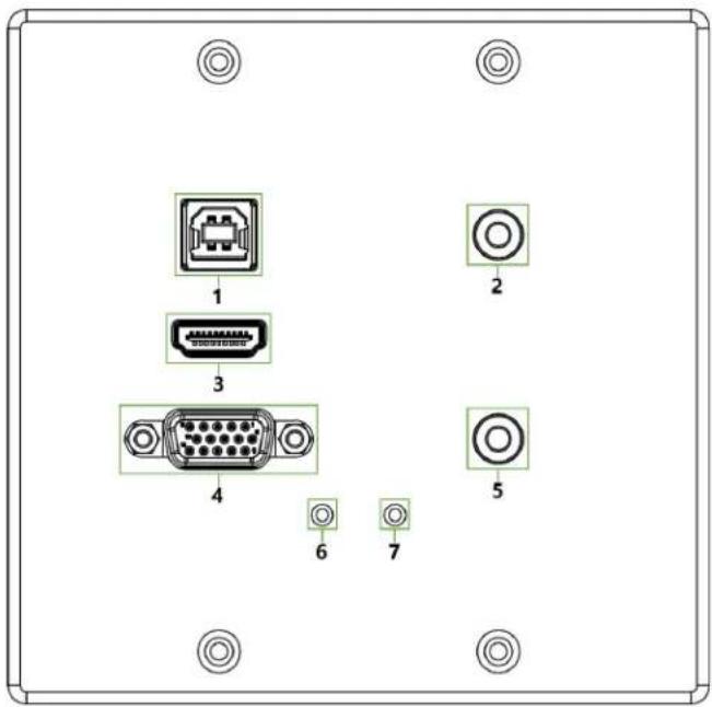
| 1 | USB HOST | • USB 2.0 Type B female connector port• USB extension for connecting to a computer or USB 2.0 devices• Supports KVM routing and hosting |
| 2 | RS232 CONTROL | • 3.5mm stereo jack (TRS) female connector port• Sends encapsulated/virtualized RS-232 (serial pass-through) over IP via the MXNet API• Supports serial routing with direct connection to a control system processor |
| 3 | HDMI IN | • 19-pin HDMI Type A female connector port• Source device input for HDMI connection |
| 4 | VGA IN | • 15-pin VGA female connector port• Source device input for VGA connection |
| 5 | AUDIO INPUT | • 3.5mm stereo jack (TRS) audio input port• Auto-detects input once directly connected, overrides HDMI input audio |
| 6 | INPUT STATUS | • AUTO-SENSE LED status indicator light• Illuminates only when an active source is connected to VGA IN port |
| 7 | LINK | • Blue LED status indicator light• Illuminates only when an active source is connected to HDMI IN port |
Encoder Wall Plate Rear and Side Panels
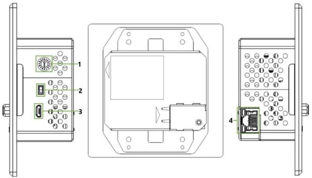
1 EDID DIAL
• Dial for manually setting an EDID on the encoder wall plate

| EDID SETTINGS | |
| EDID FOLLOW SOFTWARE (default) | 0 |
| 1080P 2D 6CH | 1 |
| 1080P 3D 6CH | 2 |
| 1080P 3D 6CH | 3 |
| 4K30Hz 3D 2CH | 4 |
| 4K30Hz 3D 6CH | 5 |
| 4K30Hz 3D 8CH | 6 |
| 1080P 2D 2CH HDR | 7 |
| 1080P 2D 6CH HDR | 8 |
| 1080P 3D 2CH HDR | 9 |
| 1080P 3D 6CH HDR | A |
| 4K30Hz 3D 2CH HDR | B |
| 4K30Hz 3D 6CH HDR | C |
| 4K30Hz 3D 8CH HDR | D |
| 1920 x 1200 3D 2CH HDR | E |
| USER EDID | F |
2 USB FUNCTION
• FPGA/MCU toggle switch
• Service function for AVPro Edge technical assistance
3 USB PROPRIETARY
• Micro-USB Type B female connector port
• Service port for AVPro Edge technical assistance
4 1GbE NETWORK
• 8-pin RJ-45 female connector, 1000BASE-T copper Ethernet port
• Supports standard PoE power, IEEE 802.3AF (15.4 W)
• Maximum power consumption of 6.5 W
• 10/100/1000Mbps auto-negotiation
• MDI/MDI-X cable mode auto-negotiation
• Maximum distance 100m (330ft) over Cat5e and higher
3.4 AC-MXNET-1G-D / AC-MXNET-1G-DV2
Decoder Front Panel

Decoder Rear Panel

| 1 | POWER STATUS | Blue LED status indicator lightSlowly pulsates until startup is complete after a reboot, at which point the light will turn solid blue |
| 2 | LINK STATUS | Green LED status indicator lightContinuously flashes until an output device is connected to the HDMI OUT port on the decoder, at which point the light will turn solid green |
| 3 | EDID COPY | Press to copy the EDID of the sink device connected to the HDMI OUT port on the back of the decoder |
| 4 | RS232 | 3-pin terminal block connector portSends encapsulated/virtualized RS-232 (serial pass-through) over IP via the MXNet APISupports serial routing with direct connection to a control system processor |
| 5 | I-PASS | 3.5mm stereo jack (TRS) IR receiver portSends IR signal pass-through via an IR emitter, IR bridge, or control system processor |
| 6 | IR-EYE | 3.5mm stereo jack (TRS) IR receiver portSupports a flashing IR emitter from an IR bridge or control system processor |
| 7 | IR OUT | 3.5mm mono jack (TS) IR receiver portSends encapsulated/virtualized IR signals upstream via the API |
| 8 | IP MONITOR | Built-in front panel mini-OLED screen "data window"Displays decoder's custom name or MAC address (if no custom name is assigned) and IP address |
| 9 | USB 1 | USB 2.0 Type A female connector portSupports routing USB 2.0 signals to a designated host encoder |
| 10 | USB 2 | • USB 2.0 Type A female connector port• Supports routing USB 2.0 signals from the decoder to the designated host encoderNOTE: Chipset V1 Decoders do not support High-speed USB connections. Chipset V2 Decoders can support one isochronous connection to a High-speed USB device (such as a microphone or digital camera). |
| 11 | USB SELECT | • FPGA/MCU toggle switch• Used for configuring the decoder for point-to-point connection with an MXNet 1G encoder (default setting is MCU ISP) |
| 12 | USB | • Micro-USB Type B female connector port• Used for configuring the decoder for point-to-point connection with an MXNet 1G encoder |
| 13 | 1GbE NETWORK | • 8-pin RJ-45 female connector, 1000BASE-T copper Ethernet port• Supports standard PoE power, IEEE 802.3AF (15.4 W)• Maximum power consumption of 6.5 W• 10/100/1000Mbps auto-negotiation• MDI/MDI-X cable mode auto-negotiation• Maximum distance 100m (330ft) over Cat5e and higher |
| 14 | BI DIR. O.M. LC FIBER | • Bidirectional SFP fiber optic connector port• Supports single mode or multimode SFP modules for extremely long runs• Recommended single mode fiber: LC to LC 1310nm, up to 40km (24.85 miles)• Recommended multimode fiber: LC to LC 850nm, up to 550m (1804 feet) |
| 15 | HDMI OUT | • 19-pin HDMI Type A female connector port• HDMI connection for endpoint device signal output• Copy EDID functionality used in conjunction with front panel button press |
| 16 | AUDIO OUT | • 3.5mm stereo jack (TRS) audio output port• De-embedded audio, extracts stereo analog audio |
| 17 | RESET | • Recessed button, use a paperclip or pen to press in and hold for 7 seconds to restore decoder to factory default settings |
| 18 | [Optional] POWER | • DC 12V/1A locking ring power charger to locally power decoder• Not required when connecting decoder to a network switch that provides PoE |
3.5 AC-MXNET-CBOX
CBOX Front Panel

CBOX Rear Panel

| 1 | STATUS MONITOR A | Built-in front panel mini-OLED screen "data window"Displays the MXNet LAN and system control network information |
| 2 | SCROLL BUTTON A | Press to cycle through the network settings on the STATUS MONITOR A screen |
| 3 | STATUS MONITOR B | Built-in front panel mini-OLED screen "data window"Displays the MXNet AV network information |
| 4 | SCROLL BUTTON B | Press to cycle through the network settings on the STATUS MONITOR B screen |
| 5 | DHCP | Press button to toggle between DHCP (default) and STATIC IP mode |
NOTE: It is recommended to change the IP address to STATIC after all the MXNet devices have been successfully installed and the Mentor web UI has been accessed.
6 SYSTEM RESET - Recessed button, use a paperclip or pen to press in and hold for 7 seconds to restore all factory default settings
7 PROPRIETARY USB • Service port for AVPro Edge technical assistance
8 PORT 1 MENTOR LAN / CONTROL • 8-pin RJ-45 female connector port • Connects to a LAN, router, or third-party control system processor
9 PORTS 2-7 - (6x) 8-pin RJ-45 female connector ports - Supports standard PoE power, IEEE 802.3AF (15.4 W) - Maximum power consumption of 4.5 W - Maximum distance 100m (330ft) over Cat5e and higher - LAN network extender for MENTOR PORT 1
| Connects to a variety of devices including control CPUs, DSPs, and the MXNet network switches, AC-MXNET-SW10, AC-MXNET-SW24, and AC-MXNET-SS48NOTE: For advanced network data tracking, one of Ports 2-7 must be directly connected to the MGMT port on the network switch (applies only to the AC-MXNET-SW24 and AC-MXNET-SW48). Connect any of Ports 2-7 to the MGMT port on the MXNet network switch to track switch performance and data usage with the Mentor web UI. | |
| 10 MXNET (PoE)AV NETWORK | 8-pin RJ-45 female connector portSupports standard PoE power, IEEE 802.3AF (15.4 W)Connects to any 1GbE port on the MXNet network switch to provide PoE to the CBOX and Mentor control connection to the encoders and decoders |
| 11 RS232 | 3-pin terminal block connector portSystem control port for MXNet using RS-232Default Baudrate is 115200 |
| 12 [Optional]POWER | DC 12V/1A locking ring power charger to locally power the CBOXNot required when connecting the CBOX to a network switch that provides PoE |
3.6 AC-MXNET-SW10
10-Port Network Switch Front Panel

10-Port Network Switch Rear Panel

natural_image
Pure electrical circuit lines without any symbols| 1 | POWER SUPPLY | · 100~240V AC, 50~60Hz 3A power input· Total power consumption is less than 132 W· PoE+ budget of 124 W |
| 2 | GROUND SCREW | · Connect with a grounding cable to the conducting parts |
| 3 | RST | · Recessed button, use a paperclip or pen to press in and hold for 7 seconds to restore network switch to factory default settings |
| 4 | DIAG / PWR | · Green LED status indicator lights· DIAG light steadily flashes green to indicate a continuous diagnostic of the system and the network switch is running on normal operations· PWR light stays solid green to indicate the switch is powered on |
| 5 | ACTIVITY LIGHTS 1-10 | · Green LED status indicator lights· Steady flickering green light to indicate network activity is present |
| 6 | 1GbE COPPER PoE PORTS 1-8 | · (8x) 8-pin RJ-45 female connector ports, 1000BASE-T copper Ethernet· Supports standard PoE power, IEEE 802.3AF (15.4 W)· Maximum power consumption of 6.5 W· 10/100/1000Mbps auto-negotiation· MDI/MDI-X cable mode auto-negotiation· Maximum distance 100m (330ft) over Cat5e and higher· Connects to the encoders, decoders, and CBOX |
| 7 | 1GbE / SFP COMBO PORTS 9-10 | · Supports a 1 Gigabit Ethernet copper connection or SFP fiber module for longer runs to the BI DIR. O.M. LC Fiber port on the encoders and decoders |
| 8 | CONSOLE | · 8-pin RJ-45 female connector port· Used for accessing the MXNet CLI |
3.7 AC-MXNET-SW24
24-Port Network Switch Front Panel

24-Port Network Switch Rear Panel

natural_image
Front view of a rectangular electronic device with two labeled ports (10 and 11), no text or symbols present.| 1 | ACTIVITY LIGHTS 1-28 | · Green LED status indicator lights· Steady flickering green lights to indicate network activity is present |
| 2 | 1GbE COPPER PoE PORTS 1-20 | · (8x) 8-pin RJ-45 female connector ports, 1000BASE-T copper Ethernet· Supports standard PoE power, IEEE 802.3AF (15.4 W)· Maximum power consumption of 6.5 W· 10/100/1000Mbps auto-negotiation· MDI/MDI-X cable mode auto-negotiation· Maximum distance 100m (330ft) over Cat5e and higher· Connects to the encoders, decoders, and CBOX |
| 3 | 1GbE / SFP COMBO PORTS 25-28 | · Supports a 1 Gigabit Ethernet copper connection or SFP fiber module for longer runs to the BI DIR. O.M. LC Fiber port on the encoders and decoders |
| 4 | 10 GIGABIT/SFP+ PORTS 49-52 | · Used for stacking multiple network switches together with 40G link aggregation |
| 5 | USB 2.0 PORT | · Used for managing the switch's network configuration settings |
| 6 | MGMT PORT | · 8-pin RJ-45 female connector port· Used for managing the switch's network configuration settings and tracking system data.· Connects to any port (2-7) on the AC-MXNET-CBOX for tracking switch performance using the Mentor web UI. |
| NOTE: This is a required physical connection in order to fully access the switch's Switch Management page within the Mentor web UI. | ||
| 7 | SYSTEM STATUS LIGHTS | · POE LED remains solid green to indicate PoE is present on the switch· DIAG LED steadily flashes green to indicate a continuous diagnostic of the system is running on normal operations· PWR LED remains solid green to indicate the switch is powered onMGMT LED steadily flashes green to indicate a stable link is present on the MGMT port |
| 8 | RST | Use a paperclip or pen to press in and hold for 7 seconds to reset the network switch to factory default settings |
| 9 | CONSOLE PORT | 8-pin RJ-45 female connector portUsed for accessing the MXNet CLI (Command Line Interface) |
| 10 | 100~240V AC,50~60Hz 3APOWER SUPPLY | Main AC power supply for the network switch |
| 11 | GROUND SCREW | Connect with a grounding cable to the conducting parts |
3.8 AC-MXNET-SW48
48-Port Network Switch Front Panel

48-Port Network Switch Rear Panel

1 ACTIVITY LIGHTS 1-48 Green LED status indicator lights Steady flickering green lights to indicate network activity is present
2 MODE BUTTON • Press to toggle on/off the PoE status light.
3 SYSTEM STATUS LIGHTS • POE LED remains solid green to indicate PoE is present on the switch • DIAG LED steadily flashes green to indicate a continuous diagnostic of the system is running on normal operations • PWR LED remains solid green to indicate the switch is powered on • MGMT LED steadily flashes green to indicate a stable link is present on the MGMT port
4 USB 2.0 PORT • Used for managing the switch's network configuration settings
5 MGMT PORT • 8-pin RJ-45 female connector port • Used for managing the switch's network configuration settings and tracking system data.
- Connects to any port (2-7) on the AC-MXNET-CBOX for tracking switch performance using the Mentor web UI.
NOTE: This is a required physical connection in order to fully access the switch's Switch Management page within the Mentor web UI.
6 CONSOLE PORT • 8-pin RJ-45 female connector port • Used for accessing the MXNet CLI (Command Line Interface)
7 1GbE COPPER PoE (48x) 8-pin RJ-45 female connector ports, 1000BASE-T copper Ethernet
• Supports standard PoE power, IEEE 802.3AF (15.4 W)
• Maximum power consumption of 6.5 W
• 10/100/1000Mbps auto-negotiation
• MDI/MDI-X cable mode auto-negotiation
• Maximum distance 100m (330ft) over Cat5e and higher
- Connects to the encoders and decoders
| 8 | 10 GIGABIT/SFP+PORTS 49-52 | Used for stacking multiple network switches together with 40G link aggregation |
| 9 | -52V~-57V~18APOWER SUPPLY | Backup DC power supply for the network switch |
| 10 | 100-240V~:50/60Hz15A | Main AC power supply for the network switch |
| 11 | GROUND SCREW | Connect with a grounding cable to the conducting parts |
4 WIRING AND CONNECTIONS
4.1 1G Ethernet/LAN
The AC-MXNET-CBOX PORT 1 MENTOR LAN/CONTROL port is a standard 8-pin RJ-45 female connector port that uses 1G data bandwidth to connect any network compliant device to transmit its data onto the Ethernet network.
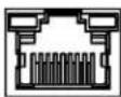
The recommended termination is based on TIA/EIA T568A or T568B standards for the wiring of the twisted pair cables:
T568A
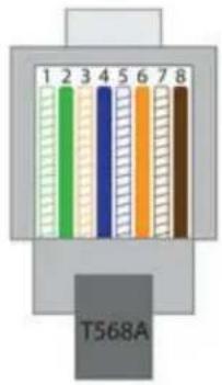
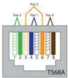
PIN 1: GREEN/WHITE
PIN 2: GREEN
PIN 3: ORANGE/WHITE
PIN 4: BLUE
PIN 5: BLUE/WHITE
PIN 6: ORANGE
PIN 7: BROWN/WHITE
PIN 8: BROWN
T568B
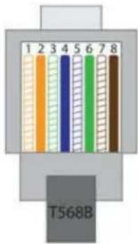
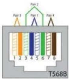
PIN 1: ORANGE/WHITE
PIN 2: ORANGE
PIN 3: GREEN/WHITE
PIN 4: BLUE
PIN 5: BLUE/WHITE
PIN 6: GREEN
PIN 7: BROWN/WHITE
PIN 8: BROWN
4.2 AV NETWORK
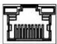
The AC-MXNET-CBOX MXnet (PoE) AV NETWORK port uses a standard RJ-45 port complying with IEEE 802.3 Ethernet standards. This port is used for communication with the MXNet AV over IP Network, powering the endpoint devices and AC-MXNET-CBOX via PoE, and connects to any 1 Gigabit Ethernet port on the MXNet 1G network switches.
The MXNet endpoint devices (encoders and decoders) use an Ethernet connection from their 1GbE NETWORK port with PoE from the 1 Gigabit Ethernet port of the MXNet network switches.
4.3 SFP and SFP+ Transceiver Modules
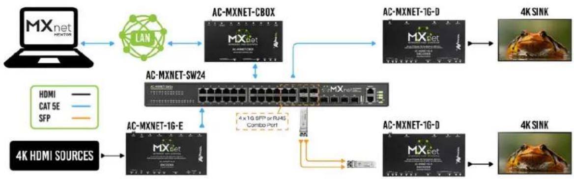
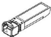
SFP (small form-factor pluggable) transceivers are compact, hot-pluggable devices that act as an interface between networking equipment (network switches, routers, network cards, etc.) and interconnecting cabling (copper or fiber).
While SFP and SFP + transceivers are both similar in size and appearance, the main difference is that SFP+ can be used in 10 Gigabit Ethernet applications, while SFP is for 100/1000BASE applications. SFP+ can also operate at 100/1000BASE. SFP complies with standards of IEEE 802.3 and SFF-8472, while SFP+ is based on SFF-8431.
MXNet can send many gigabytes of data per second with either copper or fiber connections. RJ-45 copper connections are cost-effective, but when security and stability are critical, the SFP module is recommended.
flowchart
graph TD
    A["MXnet MENTON"] <--> B["LAN"]
    B <--> C["AC-MXNET-CBOX"]
    C <--> D["AC-MXNET-1G-D"]
    D --> E["4K SINK"]
    F["4K HDMI SOURCES"] --> G["AC-MXNET-1G-E"]
    G <--> H["4x1G SFP or RJ45 Comico Port"]
    H --> I["AC-MXNET-1G-D"]
    I --> J["4K SINK"]
    C <--> K["AC-MXNET-SW24"]
    K <--> L["4x1G SFP or RJ45 Comico Port"]
    L --> M["AC-MXNET-1G-D"]
    M <--> N["4K SINK"]
The module is inserted into the SFP slot on the MXNet devices and is used for network connection and AV transmission. SFP modules are not supplied with the devices.

NOTE:
The MXNet network switches are compatible with most SFP and SFP+ transceivers on the US market. Functionality can be guaranteed with manufacturers 10Gtek® and HiFiber© as these have been tested and verified by AVPro Edge. The SFP+ ports can also operate at 1GbE speed, meaning that the AC-MXNET-SW48 can operate as a 52 port 1GbE switch, allowing for connections of up to 52 MXNet endpoints (CBOX, encoders, and decoders).

IMPORTANT:
The AC-MXNET-SW10 network switch has two SFP ports, while the AC-MXNET-SW48 has four SFP+ ports. The AC-MXNET-SW24 has both four SFP ports and four SFP+ ports.

IMPORTANT:
Only one of the network ports is available at a time on the MXNet network switches, either the SFP or RJ-45. When an SFP is connected to a network, the RJ-45 port is disabled.
4.3.1 Compatible SFP and SFP+ Transceiver Modules Specifications for MXNet Network Switches
SFP
• SFP-SX-L transceiver 1000Base-SX SFP (850nm, MMF, 550m)
• SFP-LX-L transceiver 1000Base-LX SFP (1310nm, SMF, 10km or MMF, 550m)
- SFP-LX-20-L transceiver 1310nm light wave, 9/125um single mode fiber: 20km
• SFP-LX-40 transceiver 9/125um single mode fiber: 40km
• SFP-LH-70-L transceiver 9/125um single mode fiber: 70km
• SFP-LH-120-L transceiver 9/125um single mode fiber: 120km
- SFP-1000Base-T Gigabit Ethernet RJ-45 SFP copper module, 1.25Gb/s, operates on R-J45 cable (Cat5e/6/7) spans of up to 100m (328ft) in length
SFP+
• SFPX-SR transceiver 10GBase-SR SFP+ (850nm, MMF, 550m)
• SFPX-LR transceiver 10GBase-LR SFP+ (1310nm, SMF, 10km)
- 10Gbase-T module: 10Gb/s SFP+ to RJ-45 Ethernet copper transceiver, support links up 30m (98ft) over Cat6a/7 cable. SFF-8431 MSA, SFF-8432 MSA, and IEEE 802.3az compliant
- 10Gbase-T module: 10Gb/s SFP+ to RJ-45 Ethernet copper transceiver, support links up to 80m (262ft) over Cat6a/7/8. cable SFF-8431 MSA, SFF-8432 MSA, and IEEE 802.3az compliant
4.3.2 Installing SFP and SFP+ Transceiver Modules
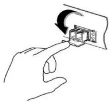
The procedure for installing SFP and SFP+ transceiver modules is shown below:
1 Put on an ESD wrist strap (or antistatic gloves).
2 Insert the SFP or SFP+ transceiver to the guide rail inside the fiber interface line card. Do not put in the SFP or SFP+ transceiver upside down.
3 Push the SFP or SFP+ transceiver along the guide rail gently until you feel the transceiver snap into place at the bottom of the line card.
natural_image
Hand inserting a small component into a device (no text or symbols visible)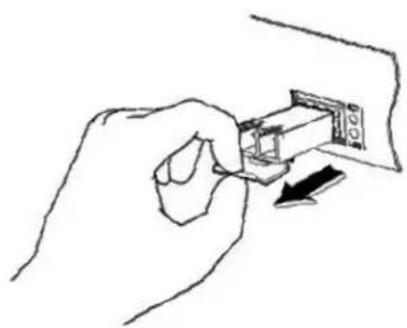
natural_image
Hand holding a small electronic component with an arrow indicating direction (no text or symbols)
TIP:
The SFP and SFP+ transceiver modules are hot-swappable, meaning that they can be inserted or removed while power is still present in the system.

WARNING:
Do not stare directly at the two fiber bores inside the SFP or SFP+ transceiver module while the network switch is operating as the laser may harm the eyes.
4.3.3 Short Reach (SR) SFP or Long Reach (LR) SFP
Single mode SFP transceivers can transmit anywhere from 2km up to 80km in distance. Standard single mode SFPs may transmit up to 10km, while extended single mode SFPs can be up to 80km.
Multimode SFPs are an ideal solution for shorter distances and are more cost-effective. Standard multimode SFPs can transmit up to 550m, while extended multimode SFPs can go up to 2km.
4.4 DAC Cables
A DAC (Direct Attach Copper) cable is a twinaxial copper cable that directly connects the ports between the active devices, such as network switches, routers, servers, and data storage devices within a network.
Both the AC-MXNET-SW24 and AC-MXNET-SW48 network switches are stackable, meaning that the can operate either as a standalone unit or stack with other network switches via the four 10G SFP+ ports with DAC cables. The AC-MXNET-SW10 does not have SFP+ ports and can only send or receive one source on one 1G SFP port.
4.5 HDMI Cables
The MXNet devices use standard 19-pin HDMI female connector ports for the inputs and outputs.

Some important things to consider when planning or installing MXNet devices:
- Ensure all HDMI cables and devices can support the signal being sent. For most use cases, a High-Speed HDMI cable with Ethernet rated for 18Gbps will be more than sufficient to satisfy signal transport if every device can handle the signal.
- Ensure your HDMI cable is the correct length. The current HDMI specification calls for cables to be between 2 to 10 meters (6.6 to 33 feet). Smaller wire cables may be unable to transmit higher bandwidth signals like 4K60 over distances of even 5 meters (16 feet).
4.6 USB Ports
The USB ports allow USB 2.0 extension. The encoder contains one USB 2.0 Type B port, and the decoder contains two USB 2.0 Type A ports.
Both the encoder and decoder also contain one micro-USB Type B port. This is a courtesy port and is primarily intended for AVPro Edge technical support servicing in the event of troubleshooting, or for configuring the encoder and decoder for standalone point-to-point applications.

Type A

Type B

Micro-USB

NOTE:
Chipset V1 decoders do not support High-Speed USB 2.0 device connections, while the Chipset V2 decoders can support one isochronous connection to a Hi-Speed USB 2.0 device (such as a digital camera) using either USB port 1 or USB port 2 on the V2 decoder. See 6.13.1 USB & KVM.
4.7 RS-232 Wiring
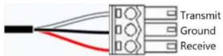
Serial control connections are made using the provided 3-pin terminal block connector. The wire slips into the hole and locks with a screw located at the top of the connector.
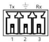
RS-232 Control
| PIN 1 | Transmit |
| PIN 2 | Ground |
| PIN 3 | Receive |
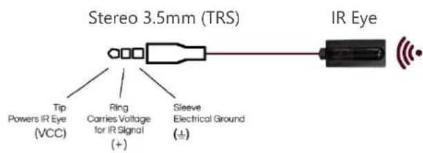
4.8 IR Wiring
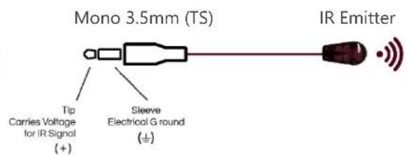
IR connections are made using the provided 3.5mm IR Emitter and IR Eye (receiver).
4.9 Analog Audio Ports
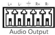
The AC-MXNET-1G-E and AC-MXNET-1G-E-AVDM encoders contain one 3.5mm stereo audio input port and one 5-pin terminal block balanced audio output port.

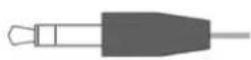
Audio Input
The AC-MXNET-1G-D decoder contains one 3.5mm stereo audio output port.

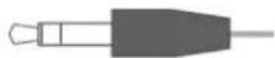
Audio Output
4.10 AC Power Connection

SURGE PROTECTION:

ELECTRICAL DISCONNECT:
Use a surge-protected circuit for all components and power supplies.
The power source outlet and power supply input sockets should be easily accessible to disconnect power in the event of an electrical hazard or malfunction.
5 INSTALLATION
All of the MXNet network switches are preconfigured out-of-the-box for AV over IP applications, meaning the network settings of each individual encoder, decoder, CBOX, and network switch do not need to be configured separately. Simply make the physical connections between the devices and MXNet will automatically discover each encoder and decoder, receive each MAC address, auto-assign IP addresses and multicast channels, and replicate the physical system in a digital space that can be accessed by using the Mentor web interface.
5.1 Connecting the Devices
- Connect an HDMI cable between the HDMI IN port on the encoder and an HDMI source device.

- Connect an HDMI cable between the HDMI OUT port on the decoder and an HDMI output device.

- Power on the source and output devices, then connect the power supply to the MXNet network switch.

NOTE:
The CBOX, encoders, and decoders will be powered via PoE from the MXNet network switch.
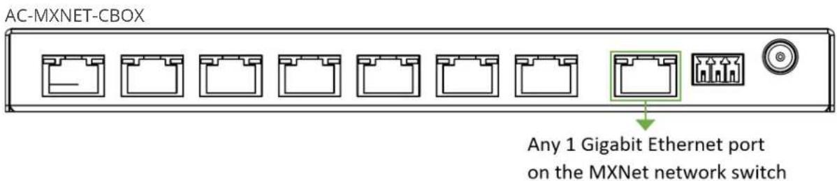
- Connect a Cat5e (or better) cable between the MXnet (PoE) AV NETWORK port on the CBOX to any 1 Gigabit Ethernet port on the MXNet network switch.
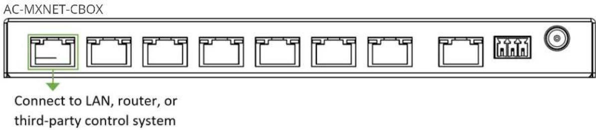
- Connect a Cat5e (or better) cable between the PORT 1 MENTOR LAN/CONTROL port on the CBOX to the LAN, router, or third-party control system.
- Locate the IP address on the CBOX by pressing the STATUS MONITOR A button to cycle through all the different network settings, including the IP address.

-
Open a new tab in any web browser and enter in the IP address of the CBOX. This will open the Mentor web interface welcome page.
-
The MXNet installation is now complete and ready to access the online MXNet Mentor web UI.
Once all of the MXNet devices are successfully connected and the Mentor web UI is accessed, MXNet will configure each encoder and decoder automatically.
5.2 Point-to-Point Setup
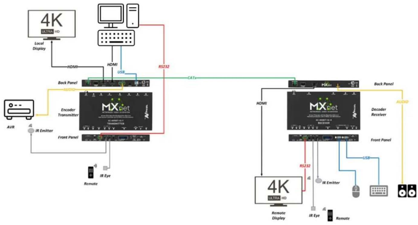
The AC-MXNET-1G-E and AC-MXNET-1G-E-AVDM encoders support a direct point-to-point connection (unicast) with the AC-MXNET-1G-D decoder.
Video, audio, RS-232, IR, and USB signals can be distributed up to 100 meters through Category cable, and 40 kilometers through single mode fiber and SFP modules.
The diagram below shows the connections of the AC-MXNET-1G-E encoder and AC-MXNET-1G-D decoder in a point-to-point application.
flowchart
graph TD
    A["4K ULTRA HD"] -->|Local Display| B["Back Panel"]
    B --> C["Encoder Transmitter"]
    C --> D["MXnet"]
    D --> E["Front Panel"]
    E --> F["4K ULTRA HD"]
    F --> G["Remote Display"]
    F --> H["IR Eye"]
    F --> I["RS232"]
    I --> J["Auto"]
    J --> K["Back Panel"]
    K --> L["Decoder Receiver"]
    L --> M["Front Panel"]
    M --> N["RS232"]
    N --> O["Audio"]
    O --> P["4K ULTRA HD"]
    P --> Q["Remote Display"]
    P --> R["IR Eye"]
    P --> S["Remote"]
    C --> T["AC-AMRNET-VLT TRANSMITTER"]
    T --> U["HD/USB"]
    U --> V["RS232"]
    V --> W["Back Panel"]
    W --> X["Decoder Receiver"]
    X --> Y["Front Panel"]
    Y --> Z["RS232"]
    Z --> AA["Audio"]
5.2.1 Configuring Encoders and Decoders
MXNet encoders and decoders operate in unicast mode by factory default but will automatically be set to multicast mode by the AC-MXNET-CBOX when connected to the network switch. Once set to multicast mode, the encoders and decoders must be set back to unicast mode again prior to point-to-point installation.
Both the encoder and decoder must also be assigned the channel number 0000 and set to unicast mode prior to point-to-point installation. This procedure is outlined in the steps below and must be completed on both the encoder and decoder.
Requirements: - Windows based PC or Laptop with internet connection
- Micro-USB to USB Type A cable
- Serial Configuration Software Tool AC-MXNET-1G-SCT
(available for download, located at Support.AVProEdge.com)
- On both the encoder and decoder, flip the USB SELECT toggle switch to the FPGA DEBUG setting.
AC-MXNET-1G-E encoder

AC-MXNET-1G-D decoder

natural_image
Front panel of a computer interface showing icons for buttons, ports, and media (no text or labels visible)- Connect the micro-USB to USB Type A cable between the encoder or decoder and PC.
AC-MXNET-1G-E encoder

AC-MXNET-1G-D decoder

- Open the Serial Configuration Software Tool AC-MXNET-1G-SCT and select the Open button to open the PC serial port.
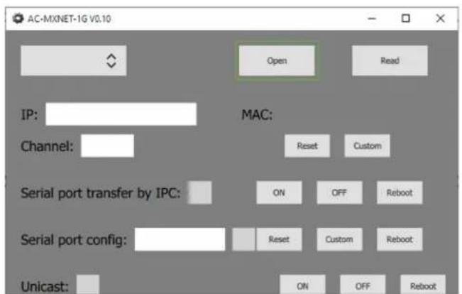
-
Select the Read button to generate the serial port configuration information.
-
Select the Custom button and enter 0000 into the Channel field.
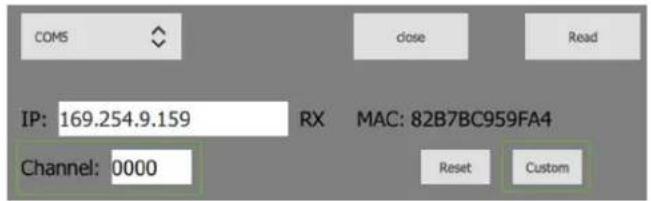
- Select the On button to change the encoder to unicast mode, then select the Reboot button.
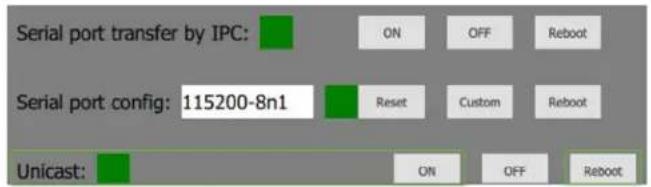
- Repeat these steps per every encoder/decoder as needed.
5.3 Stacking Switches
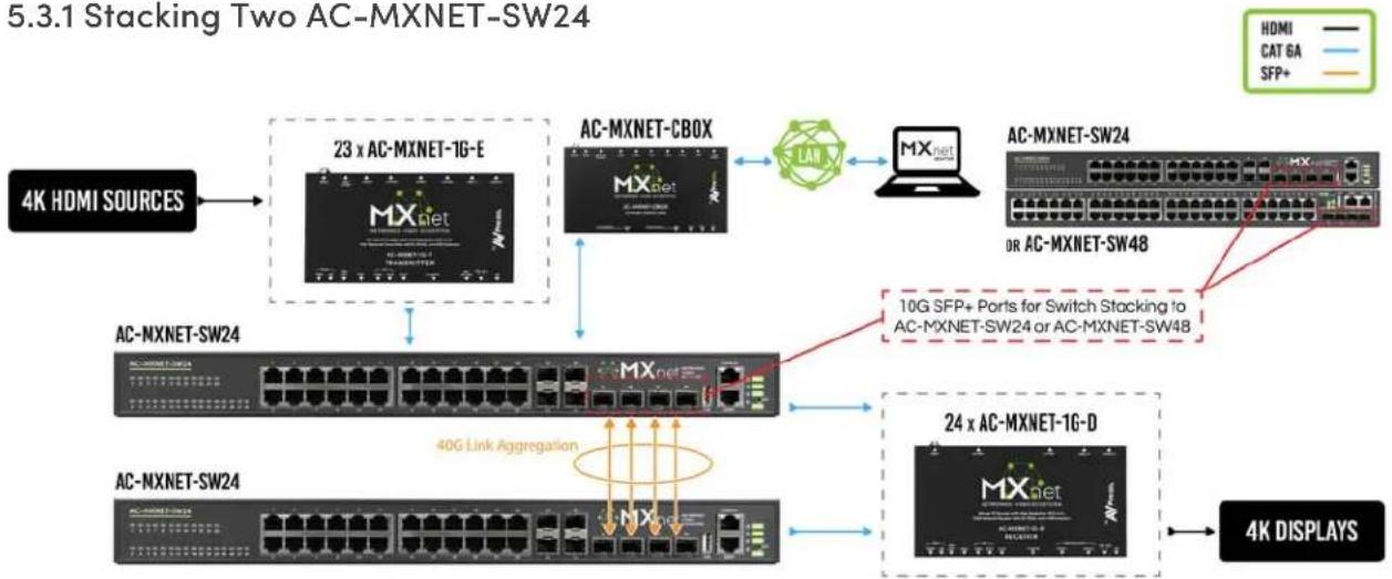
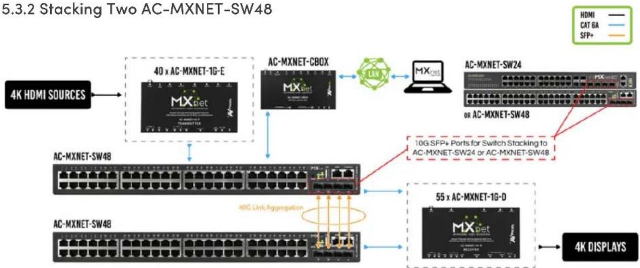
The AC-MXNET-SW24 and AC-MXNET-SW48 network switches can be stacked together by connecting up to four SFP+ ports between the two switches. Each SFP+ port provides 10G uplink between each switch. An SFP+ link is required per every 10 encoders; it is recommended to add an additional SFP+ link for system redundancy.
Stacking two MXNet network switches of the same model or stacking one SW24 with one SW48 requires no additional configurations on the switches. Refer to the application diagram below and simply make the connections between the two switches.

IMPORTANT:
If stacking 3 or more MXNet network switches together, contact AVPro Technical Support for further assistance as this requires additional configurations on the network switches.
5.3.1 Stacking Two AC-MXNET-SW24
flowchart
graph TD
    A["4K HDMI SOURCES"] --> B["23 x AC-MXNET-1G-E"]
    B --> C["AC-MXNET-CBOX"]
    C --> D["LAN"]
    D --> E["AC-MXNET-SW24"]
    E --> F["OR AC-MXNET-SW48"]
    F --> G["10G SFP+ Ports for Switch Stacking to AC-MXNET-SW24 or AC-MXNET-SW48"]
    G --> H["24 x AC-MXNET-1G-D"]
    H --> I["4K DISPLAYS"]
    B --> J["40G Link Aggregation"]
    J --> K["AC-NXNET-SW24"]
    K --> L["AC-NXNET-SW24"]
5.3.2 Stacking Two AC-MXNET-SW48
flowchart
graph TD
    A["4K HDMI SOURCES"] --> B["40 x AC-MXNET-1G-E"]
    B --> C["AC-MXNET-CBOX"]
    C --> D["MAC"]
    D --> E["AC-MXNET-SW24"]
    E --> F["55 x AC-MXNET-1G-D"]
    F --> G["4K DISPLAYS"]
    style A fill:#f9f,stroke:#333
    style B fill:#ccf,stroke:#333
    style C fill:#cfc,stroke:#333
    style D fill:#fcc,stroke:#333
    style E fill:#cff,stroke:#333
    style F fill:#ffc,stroke:#333
    style G fill:#fcc,stroke:#333
6 THE MENTOR WEB UI
Mentor is MXNet's proprietary HTML5-based setup and control web interface that contains a variety of easy to use, yet powerful tools and settings to help streamline the installation process. It comes pre-installed on every AC-MXNET-CBOX and is purposefully designed for easy navigation and monitoring of the entire system.
Once all of the devices are connected and powered on, the Mentor homepage can be accessed using the following steps below.
6.1 Accessing Mentor
- Locate the IP address on the CBOX by pressing the STATUS MONITOR A button to cycle through all the different network settings, including the IP address.
AC-MXNET-CBOX

natural_image
Front panel of a computer interface showing ports and indicators (no text or symbols)
NOTE:
The CBOX comes in DHCP IP mode by factory default. It is recommended to change the IP mode to static by using the Mentor web UI and only after all the devices are already connected to the network.
- Open a new tab in any web browser and enter in the IP address of the CBOX. This will open the Mentor web interface welcome page.
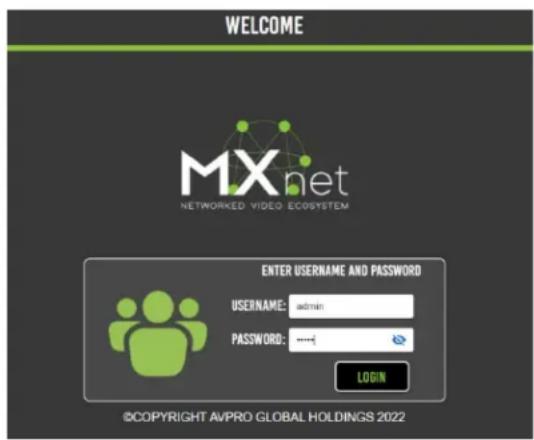
- Enter in the default username and password below to log in.
Username: admin (all lowercase)
Password: admin (all lowercase)
Both fields are case sensitive and can be changed at any time once Mentor is accessed.
6.2 Navigating the Mentor Web UI
The Mentor home screen features the System Utilities as the default page. This page provides a variety of MXNet system information, including the network configurations, current firmware versions on the CBOX, and user accessibility settings.
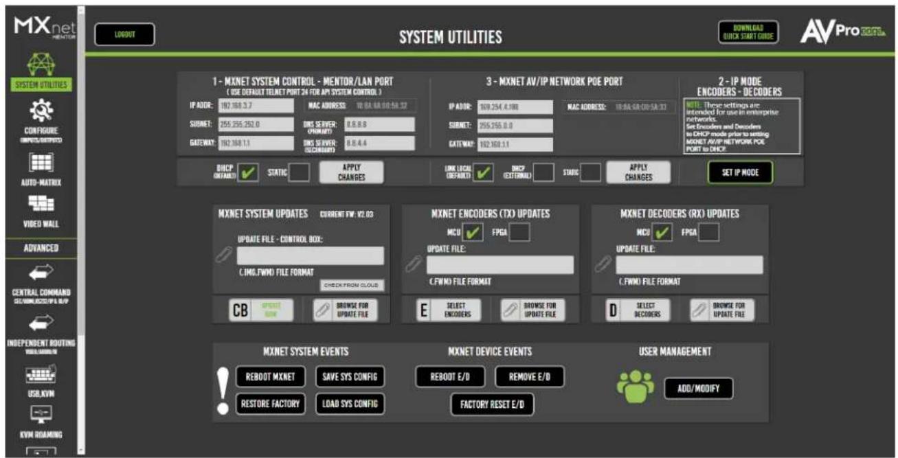
- To navigate through all the different pages, use the scroll bar and select the icons located on the left-side column of the page.

- To log out of Mentor, select the logout button in the top-left corner of the page.
- For fast and simple installations, the MXNet Quick Connect Guide can be downloaded directly from Mentor by selecting the download quick start guide button at the top-right corner of the page.
6.3 System Utilities
6.3.1 LAN and AV Network Configurations

This section provides network connection settings; it is divided into two sections:
MXNET SYSTEM CONTROL - MENTOR/LAN PORT
This section is for setting an IP address for LAN and CPU connections. The default setting is DHCP IP mode but can be changed to STATIC once communication is established with the CBOX.
MXNET AV/IP NETWORK POE PORT
This section is used for changing the IP mode for the encoders and decoders, as well as the MXnet (PoE) AV NETWORK port on the CBOX. The three options are: LINK LOCAL (default), DHCP (external), and STATIC.

IMPORTANT:
It is highly recommended to leave the IP mode set to LINK LOCAL and not change it to DHCP or STATIC unless the system is being installed in a large corporate enterprise or commercial network setting where an IT department will manage all network nodes, as this requires additional configurations that must be made to all network switches prior to making this change.
6.3.2 MXNet Firmware Updates
The current firmware version on the CBOX can be viewed and updated from here, along with the encoders and decoders. Firmware updates can be performed on multiple or individual encoders and decoders by selecting them once the firmware file has been added to the Update File field.
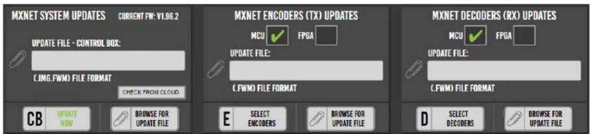
The latest firmware for the encoders, decoders, and CBOX can be located at Support.AVProEdge.com and can be installed once downloaded.
To update firmware, select the paperclip icon ☐ next to the Update File field of the device you wish to update, then select the firmware file for the MXNet device.
6.3.3 MXNet Events
This section provides commands for rebooting, removing, and factory resetting various MXNet devices. It also includes options for managing different user levels for limiting access and permission settings.

flowchart
graph LR
    A["1 MXNET SYSTEM EVENTS"] --> B["REBOOT MXNET"]
    B --> C["SAVE SYS CONFIG"]
    C --> D["RESTORE FACTORY"]
    D --> E["LOAD SYS CONFIG"]

    F["2 MXNET DEVICE EVENTS"] --> G["REBOOT E/D"]
    G --> H["REMOVE E/D"]
    H --> I["FACTORY RESET E/D"]

    J["3 USER MANAGEMENT"] --> K["ADD/MODIFY"]
1 MXNET SYSTEM EVENTS (system-wide)
The following commands are provided in this section:
- Select the reboot MXNet button to restart all the devices in the system.
- Select the restore factory button to restore all the devices in the system back to factory default settings.
- Select the save sys config button to download a .cfg file of all the current system settings and configurations.
- Select the load sys config button to upload a previously saved .cfg file and apply it to all system settings and configurations.
2 MXNET DEVICE EVENTS (device specific)
The following commands are provided in this section:
- Select the reboot E/D button to restart one or multiple encoders and decoders.
- Select the remove E/D button to remove one or multiple encoders and decoders from Mentor.
- Select the factory reset E/D button to restore one or multiple encoders and decoders back to factory default settings.
3 USER MANAGEMENT
- Select the add/modify button to change the admin user login credentials or to add a limited user account.
- Select the enable limited user toggle button to add a limited user account, including a separate username and password. The limited user account will only have access to the Auto-Matrix and Video Wall pages within Mentor.
- If the toggle button is set to OFF after entering a username and password for the limited user account, the limited user account's username and password will be saved within Mentor, and the limited user account cannot access Mentor until the admin account is accessed and the toggle button is set back to ON again.
6.4 Configure Inputs and Outputs
The Encoder & Decoder Configurations pages provide many useful tools and settings for configuring the encoders and decoders. The first three tabs will be highlighted in green to indicate which page is currently selected.

1 INPUTS/ENCODERS/SOURCES
Shows a list of all the encoders connected to MXNet along with various options for configuration.
2 OUTPUTS/DECODERS/DISPLAYS
Shows a list of all the decoders connected to MXNet along with various options for configuration.
3 ENCODER-MODULE (for AVDM Encoders only)
Shows a list of all the downmixing encoders connected to MXNet along with various options for configuration.
4 SAVE CONFIG
Select to download a .xlsx file (Microsoft Excel Worksheet) of all the current settings and configurations of the encoders and decoders.
5 REFRESH
Select to refresh the web page.
6 DIAGNOSTICS
Select to view critical system information for the encoders and decoders.
6.4.1 Inputs/Encoders/Sources
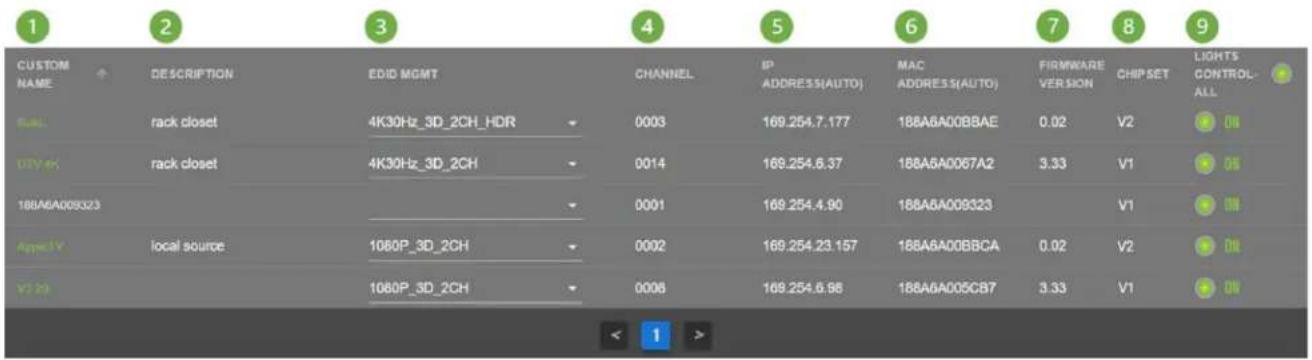
1 CUSTOM NAME (default MAC address)
Text field, limit of 12 characters. Type in a custom name and hit Enter to apply it. Custom names can be sorted by clicking on the arrow button ↗ to toggle between ascending and descending alphanumeric order.
2 DESCRIPTION
Text field, limit of 12 characters. Type in a custom description and hit the Enter key to apply it.
3 EDID MGMT
Dropdown menu containing 14 EDID presets and one User EDID slot for a custom EDID or a copied EDID either from the encoder's HDMI Loop Out (16), or from a display's decoder (17). Click on the dropdown arrow to select an EDID for the source.
4 CHANNEL
Shows the multicast/broadcast channel number of the encoder. This is automatically generated by MXNet and contains the video, audio, IR, USB, and control signals of the encoder. Switching to a source allows the decoder to subscribe to the encoder's channel in order to receive the encoder's signals.
5 IP ADDRESS (auto)
Shows the link-local IP address of the encoder. The network switch will automatically assign this to the encoder once a connection has been made.
| EDID SETTINGS | |
| 1 | 1080P 2D 6CH |
| 2 | 1080P 3D 2CH |
| 3 | 1080P 3D 6CH |
| 4 | 4K 30Hz 3D 2CH |
| 5 | 4K 30Hz 3D 6CH |
| 6 | 4K 30Hz 3D 8CH |
| 7 | 1080P 2D 2CH HDR |
| 8 | 1080P 2D 6CH HDR |
| 9 | 1080P 3D 2CH HDR |
| 10 | 1080P 3D 6CH HDR |
| 11 | 4K 30Hz 3D 2CH HDR |
| 12 | 4K 30Hz 3D 6CH HDR |
| 13 | 4K 30Hz 3D 8CH HDR |
| 14 | 1920 x 1200 3D 2CH HDR |
| 15 | USER EDID |
| 16 | Copy from Loop Out |
| 17 | Copy from Output |
6 MAC ADDRESS (auto)
Shows the MAC address of the encoder. This is a factory setting that cannot be changed.
7 FIRMWARE VERSION
Shows the version of firmware currently installed on the encoder. This can be updated on the System Utilities page under the MXNet Encoders (Tx) Updates section.
11 CHIPSET
Shows the current chipset version of the encoder.
12 LIGHTS CONTROL
Toggle button, allows for control of the front panel LEDs on the encoder, and can be done on all or individually selected encoders. Click to toggle between FLASH, OFF, and ON.
6.4.2 Outputs/Decoders/Displays
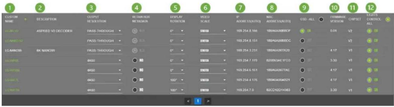
1 CUSTOM NAME (default MAC address)
Text field, limit of 12 characters. Type in a custom name and hit the Enter key to apply it.
2 DESCRIPTION
Text field, limit of 12 characters. Type in a custom description and hit the Enter key to apply it.
3 OUTPUT RESOLUTION
Dropdown menu containing nine scaling resolutions and two video modes. Click on the dropdown arrow to select an output resolution for the display.

NOTE: PASS-THROUGH sends an untouched video signal through the decoder to the display
BLACK OUT generates a solid black screen overlay to the display (audio is still present)
STREAM OFF disables the output stream entirely so no signal is present on the display
| OUTPUT RESOLUTION | |
| 1 | PASS-THROUGH |
| 2 | 720P 50Hz |
| 3 | 720P 60Hz |
| 4 | 1080P 24Hz |
| 5 | 1080P 50Hz |
| 6 | 1080P 60Hz |
| 7 | 4K 30Hz |
| 8 | 4K 50Hz |
| 9 | 4K 60Hz |
| 10 | BLACK OUT |
| 11 | STREAM OFF |
4 RETAIN HDR METADATA
If the Output Resolution scaling is not set to PASS-THROUGH, a toggle button will appear in this field instead of N/A. Selecting this will allow HDR metadata to be retained when switching between sources with Output Resolution scaling enabled.
5 DISPLAY ROTATION
Dropdown menu, allows a display to rotate its image by selecting 180^ , 270^ , or 0^ for no rotation.
6 VIDEO SCALE
Dropdown menu, allows a display to change its aspect ratio.
7 IP ADDRESS (auto)
Shows the link-local IP address of the decoder. The network switch will automatically assign this to the decoder once a connection is made.
8 MAC ADDRESS (auto)
Shows the MAC address of the decoder. This is a factory setting that cannot be changed.
9 OSD (Onscreen Display)
Toggle button, allows a display to show a red text overlay listing the decoder's custom name, MAC and IP addresses, and the currently selected encoder's custom name.
10 FIRMWARE VERSION
Shows the version of firmware currently installed on the decoder. This can be updated on the System Utilities page under the MXNet Decoders (Rx) Updates section.
11 CHIPSET
Shows the current chipset version of the decoder.
12 LIGHTS CONTROL
Toggle button, allows for control of the front panel LEDs on the decoder, and can be done on all or individually selected decoders. Click to toggle between FLASH, OFF, and ON.
6.4.3 Encoder Module (AVDM Encoders only)

1 TYPE
Shows a list of all the AVDM encoders connected to MXNet.
2 CUSTOM NAME
Text field, limit of 12 characters. Type in a custom name and hit the Enter key to apply it.
3 DESCRIPTION
Text field, limit of 12 characters. Type in a custom description and hit the Enter key to apply it.
4 ENCODER MAC ADDRESS
Shows the MAC address of the encoder. This is a factory setting that cannot be changed.
5 ENCODER CUSTOM NAME
Shows the encoder's assigned custom name from the Inputs/Encoders/Sources page.
6 FIRMWARE VERSION
Shows the version of firmware currently installed on the encoder. This can be updated in the System Utilities page under the MXNet Encoders (Tx) Updates section.
7 MODE
Dropdown menu, allows the encoder to adjust the audio downmixing by selecting one of the following preset modes:
| AVDM PRESET MODES | ||
| 1 | STD FX (default) | Standard downmixing mode |
| 2 | Low Center+ | Center Mix increased to 60% |
| 3 | Mid Center+ | Center Mix increased to 80% |
| 4 | High Center+ | Center Mix increased to 100% |
| 5 | Middle FX (recommended) | Custom AVPro Mix, including full range of sound with pronounced Center channel and small amount of LFE |
| 6 | Full FX (large 3-way systems) | Custom AVPro Mix, including full range of sound with extra Surround Mix and more LFE |
| 7 | Voice FX (voice intelligibility) | Custom AVPro Mix, including Left, Center, and Right channels 100% mixed. Surround Mix is reduced for minor effects |

TIP:
AVPro Edge and MXNet provides integrators with seven downmixing preset options, allowing them to tailor the downmixing of a source's audio, similar to how most AVR's and pre-processors can adjust the level of an individual channel in their surround mix.
6.4.4 System Diagnostics
The System Diagnostics page can be accessed by selecting the magnifying glass button 🔒 located in the top-right corner of the Configure page. This opens a separate page that shows live information and provides critical system data for advanced network tracking and cabling performance. The encoders and decoders each feature their own separate Diagnostics page located on separate tabs at the top. To exit the System Diagnostics page, select the close button CLOSE ✗ to return to the Configure page.
![1 2 3 4 5 6 7 8 9 10 11 12 CUSTOM NAME Switch Point Bandwidth Dual Time Bandwidths [MHz] POC DESCRIPTION NETWORK CONNECTION CONNECTION SPEED RANDBOWTH SETTINGS HOME VIDEO HDR COLOR DEPTH CIRONA HDMI AUTO HOT-PLUG DETECTURE SET HDCP VESS ENCOSERS LIGHTS-ALL Wpp Ethernet1/0/1 205 pmode 2000 HS AUTO 192BC160p/60Hz NO REF.YUV444 NON PCM RESET HDCP 2.2 04 DTC 2K Ethernet1/0/1 85 at-gate 2000 HS AUTO NO REF.YUV444 NO PCM RESET 04 Alpha*5 Ethernet1/0/2 422 pmode 2000 HS AUTO NO REF.YUV444 NO PCM RESET 04 VLS 2K Etherm1/0/5 2000 HS AUTO NO REF.YUV444 NO PCM RESET 04](/content/2026/05/987212/images/27f9f9eaec48c271c772a5e94f6d267e3a24203ceafdd09f9582ebf059701b4d.jpg)
1 CUSTOM NAME
Shows the encoder/decoder's assigned custom name.
2 SWITCH PORT NUMBER
Shows which port on the network switch that the encoder/decoder is plugged into. Select the refresh button to update the field.
3 REAL TIME BANDWIDTH (Mbps)
Shows the amount of bandwidth. Select the refresh button 📋 to update the field.
4 POE
Toggle button, allows PoE to be enabled or disabled to the encoder/decoder. Select the refresh button 📋 to update the field.
5 DESCRIPTION
Shows the encoder/decoder's assigned custom description.
6 NETWORK CONNECTION
Shows the quality of the network category cable connection, indicated by color:
Green Good, network connection is at 1G
Yellow Marginal, MXNet will automatically throttle bandwidth to 100Mbps
Red Failed, MXNet is unable to detect a connection to the encoder/decoder
7 CONNECTION SPEED
Shows the encoder/decoder's network connection speed.
8 BANDWIDTH SETTINGS (Encoders only)
Dropdown menu, selecting 200M sets the encoder throughput to as low as 200Mb while selecting Auto increases its bandwidth to a maximum 850Mb throughput.
HDMI VIDEO Shows the resolution of the source's video
HDR YES indicates the source is sending HDR metadata
NO indicates the source is sending SDR content
COLOR DEPTH Indicates the source is sending either 8-bit or 10-bit color depth CHROMA Indicates the source is sending either RGB or YUV color space HDMI AUDIO Indicates the source is sending either PCM or non-PCM audio
10 HOT-PLUG DETECT/RESET
Toggle button, green indicates a hot-plug detect has been identified by MXNet. Click on reset button RESET to force a refresh of the HDMI signal between the connected devices.
11 HDCP VERS
Shows the version of HDCP detected from the connected device.
12 ENCODER/DECODER LIGHTS
Toggle button, allows for control of the front panel LEDs on the encoder/decoder, can be done on all or individually selected encoders/decoders. Click to toggle between FLASHING, OFF, or ON.
The following three columns shown below are only available on the Outputs/Decoders/Displays diagnostics page.

TEST PATTERN
Dropdown menu containing options for a 1080p or 4K30 color bar test pattern that will be generated by the selected decoder for testing and troubleshooting purposes.
NOTE: This setting is not available on the AC-MXNET-1G-DV2.
CONNECTED SINK/DISPLAY
Shows the manufacturer or model number of the connected display.
SOURCE ENCODERS
Shows the source signal routed to the decoder.
6.9 Auto-Matrix
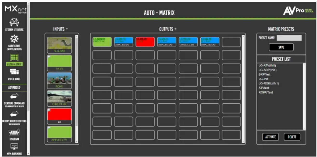
The Auto-Matrix page layout consists of the Inputs column on the left, the Outputs grid in the middle, and the Matrix Presets section on the right. Each individual tile functions as a selectable button and will auto-populate the custom names from the Configure page as a label, highlighted by an orange border to indicate the selected input and output(s).
Inputs and outputs can be sorted by clicking on the sort arrow button ↑ to toggle between ascending and descending alphanumerical order.
6.9.1 Inputs
This column lists all of the encoders, each one is represented as a labeled thumbnail that provides a preview image of the connected source's video signal and will automatically refresh every ten seconds. Each thumbnail functions as a button that can be selected to route the connected source's signals to any one or more outputs.
6.9.2 Outputs
All of the decoders are shown in this grid, each one is represented as a separate output button that is labeled with the decoder's custom name and the source that is currently routed to it. Multiple outputs can be selected at a time, indicated by an orange border, to route signals from any one of the connected source's input.

NOTE:
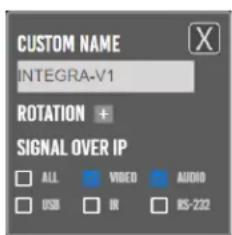
The decoder's custom name, image rotation, and aspect ratio can also be adjusted from this page by right-clicking on an output. This will open an additional menu where the signals can be selected for independent routing of video, audio, USB, IR, and RS-232 signals.
Select the + button + to open the menu settings for image rotation and aspect ratio.
6.9.3 Matrix Switching
1 From the Inputs column, select the desired source's thumbnail. This will highlight the thumbnail with an orange border to indicate the selection was made.
2 From the Outputs grid, select the desired output(s) to route the selected source to. This will highlight the output(s) with an orange border to indicate the selection was made.
3 Switching commands will now be sent to the source's encoder and the output's decoder(s), and the selected source's signals will now be present on the selected output(s).

IMPORTANT:
The AC-MXNET-1G-EV2 and AC-MXNET-1G-DV2 devices may coexist alongside MXNet first-generation encoders and decoders within previously installed systems or pending system deployments. However, they are required to be used exclusively in EVO II transmitter-to-EVO II decoder(s) pairings only. For example, you cannot route signals from a first-generation encoder/decoder to a second-generation encoder/decoder.
6.9.4 Matrix Presets
This feature provides an alternative to manually selecting and routing inputs to outputs, allowing switching commands to be saved and recalled as a preset, along with the ability to name each saved preset.
Keep in mind that when saving and activating matrix presets, settings will be applied to all current switching configurations on all the encoders and decoders.
6.9.5 Creating a Preset
1 First, select the desired inputs and switch them to the desired output(s) by using the previous steps above.
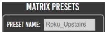
2 Under the Matrix Presets section, enter in the name of the current switching configuration into the preset name field.

TIP:
No spaces are allowed when entering text into this field. Individual words can be separated with a hyphen (-) or underscore (_).
3 Select the save button SAVE to save all of the current switching configurations as a matrix preset under the Preset List, along with its assigned name.
| PRESET LIST |
| Roku_Upstairs |
6.9.6 Activating a Preset
Once a matrix preset has been saved under the Preset List, it can be activated to automatically route the selected source signals to the selected output.
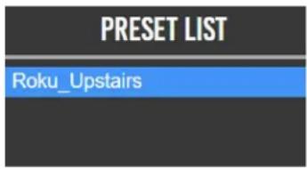
1 Select the preset's name from the Preset List, it will then be highlighted in blue to indicate the selection was made.
2 Select the activate button ACTIVATE.
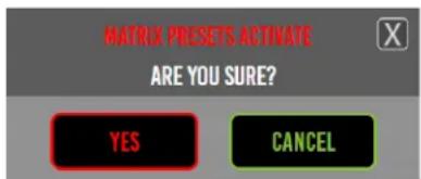
3 A dialog box will prompt the selection again. Select the yes button to confirm.
4 Switching commands will now be sent to the selected encoders and decoders, and the source's signals will be automatically routed to the outputs that were saved to the preset.
6.9.7 Deleting a Preset
1 Select the preset's name from the Preset List, it will then be highlighted in blue to indicate the selection was made.
2 Select the delete button DELETE.
3 A dialog box will prompt the selection again. Select the yes button to confirm.
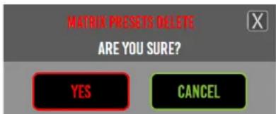
4 The preset will now be permanently removed from the Preset List and is no longer able to be activated.
6.10 Video Wall
This page contains various tools and settings for creating custom video walls, including bezel adjustments, automatic cropping, aspect ratios, and more. Video wall layout options consist of two arrays: standard and mosaic, indicated by the two tabs at the top of the page labeled Video Wall and Mosaic. Both layouts retain their video resolution, including Dolby Vision, HDR, and HDR10+ metadata.
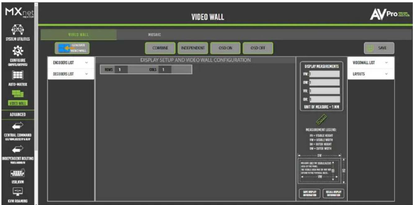
6.10.1 Standard Layout
The standard video wall layout consists of a grid array (2x2, 3x3, 4x4, etc.) with identical displays. The aspect ratio remains the same and the source's image is scaled across all the displays of the video wall. Advanced grid layouts (1x2, 2x8, etc.), where the aspect ratio of the video wall being very different from that of the individual displays, may also be configured.
6.10.2 Mosaic-Style Layout
Mosaic, or artistic, video walls do not follow the traditional standard grid-like pattern. Instead, they offer a unique and creative approach for customizing video walls, allowing the ability to mix and match displays of different sizes and orientations. Mosaic-style video walls usually play one single source across all video wall displays for an eye-catching effect.
6.10.3 Creating a Video Wall Array
The buttons at the top of the Video Wall page allow how the source's image will appear across the displays of the video wall.

flowchart
graph LR
    A["COMBINE"] --> B["INDEPENDENT"]
    B --> C["OSD ON"]
    C --> D["OSD OFF"]
COMBINE
INDEPENDENT
OSD ON and OSD OFF
One image is shown on all displays as a continuous image.
One image is shown on all displays independently.
Displays will show their OSD (On-Screen Display) information.
1 In the Video Wall tab, select the videowall list dropdown menu, and select add vw.
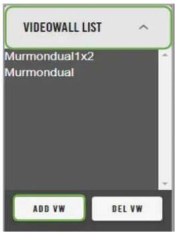
2 Enter in the video wall name, number of rows and columns, and the layout name. Then select the save video wall array button SAVE VIDEOWALL ARRAY.
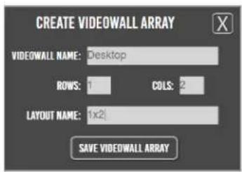
3 Mentor will then generate the "panels" of the video wall layout, with the previously saved array now appearing under the VideoWall List.
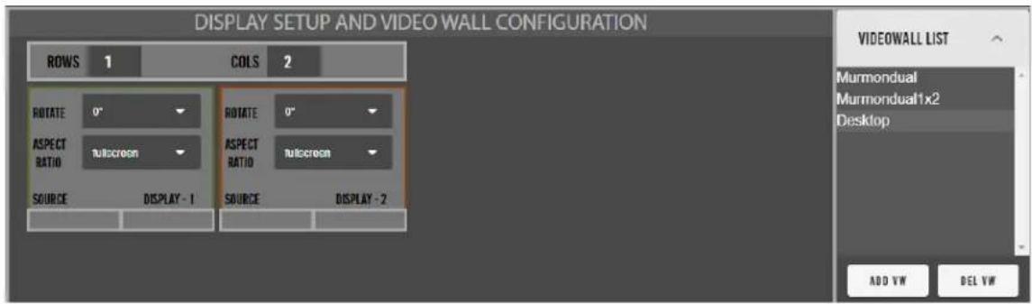
The panels are laid out similarly to how the actual video wall will be viewed in person. Each panel includes a separate dropdown menu for image rotation and aspect ratio, along with the custom names of the selected inputs and outputs, and the display number.
| ROTATE | Dropdown menu, options are 0°, 180°, or 270°. |
| ASPECT RATIO | Dropdown menu, options are fullscreen (4:3) or keep aspect ratio (16:9). |
| SOURCE | Shows the current active source on the selected display. |
| DISPLAY - # | Shows the number of the display relative to its position within the video wall layout. Numbered in ascending numerical order, left-to-right and top-to-bottom. |
4 Select the decoders list dropdown menu, this will show a list of all of the decoders as selectable buttons. Select a decoder by clicking and dragging the decoder, moving it over to the right, and dropping it onto a panel.
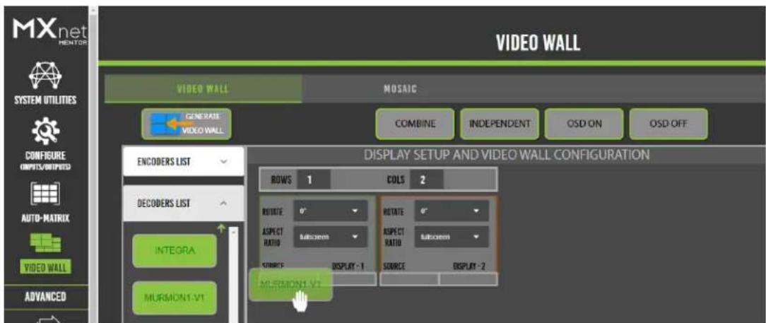
The selected display's custom name will now appear in the bottom right corner of the panel, indicating the selected display is now assigned to this panel. Repeat this step for other panels.
5 Select the encoders list dropdown menu. This will show a list of all of the encoders with their connected source's preview image as a selectable thumbnail.
6 Select the encoder by clicking and dragging the source's thumbnail, moving it over to the right, and dropping it onto a panel.
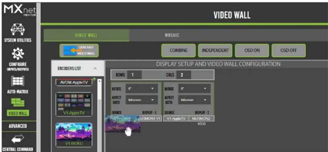
The selected source's custom name will now appear in the bottom left corner of the panel, indicating the selected source is now assigned to this display. Repeat this step for other panels.
7 Select both tiles by left clicking on them. An orange border will highlight the selected displays. Then select the combine button at the top of the page.
8 Select the save button 📂, this will save the selected inputs and outputs to the current video wall array. Then select the generate video wall button 📂. The video wall will now show the selected source content.
6.10.4 Creating a Mosaic Video Wall
1 In the Mosaic tab, select the videowall list dropdown menu and select the add vw button ADD VW.
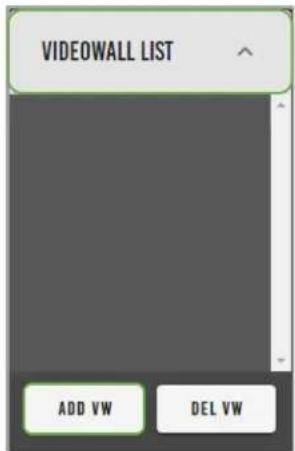
2 Enter in the video wall name, the number of rows and columns, and select the save video wall array button SAVE VIDEOWALL ARRAY
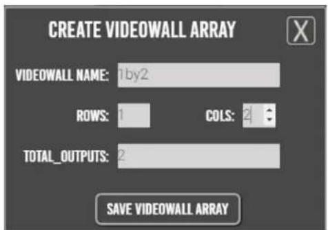
3 Mentor will then generate the "panels" of the video wall layout, with the previously saved array now appearing under the VideoWall List.
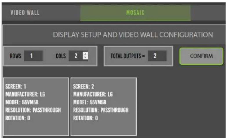
4 Select the layouts dropdown menu and select the add layout button ADD LAYOUT.
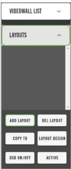

TIP:
One physical video wall can have multiple video wall layouts. Every different input source will have a new layout.
5 Enter in the layout name and select the save videowall layout button SAVE VIDEOWALL LAYOUT.
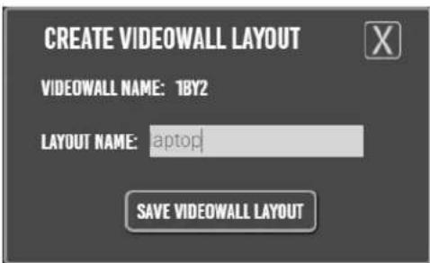
6 Select the first panel, an orange border will highlight the selected panel. Select the display's manufacturer, model, output resolution, and rotation from their respective dropdown menus, then select the save button SAVE. Repeat this step for the other panel.
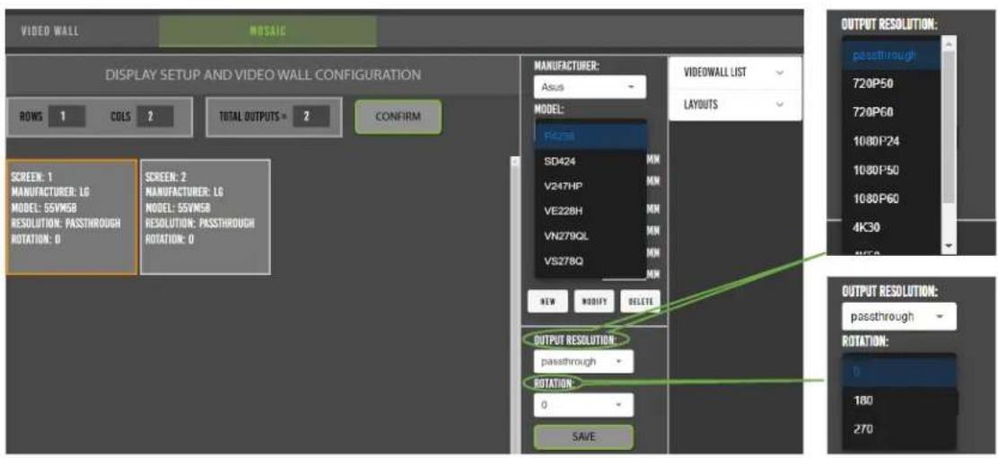

TIP:
Mentor provides an internal catalog of the most commonly used displays. Selecting the manufacturer and model from these dropdown lists will auto-populate the display's dimensions into the appropriate fields.
7 If the display is not listed under the dropdown menus, select the new button NEW to open the Display Properties window. Enter in the display's manufacturer, model, and dimensions, then select the save button SAVE.
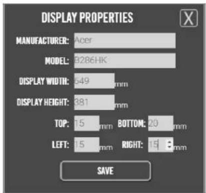
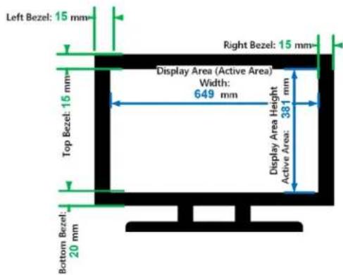
The newly added display and saved dimensions will now be added to both the Manufacturer and Model dropdown menu lists and can now be selected for the display(s).
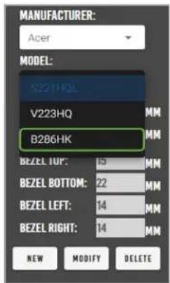
8 Select the layout design button LAYOUT DESIGN, this will open a separate window.
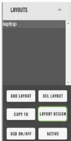
9 Mentor will generate a "canvas" for the mosaic video wall layout with the ISF® Geometry 1.78:1 test pattern for easy visual reference regarding which part of the content will be captured.
The panels can be individually adjusted by clicking and dragging the desired panels on the white background, and selecting the sync left to right button SYNC LEFT TO RIGHT, followed by selecting the save SAVE and active ACTIVE buttons.
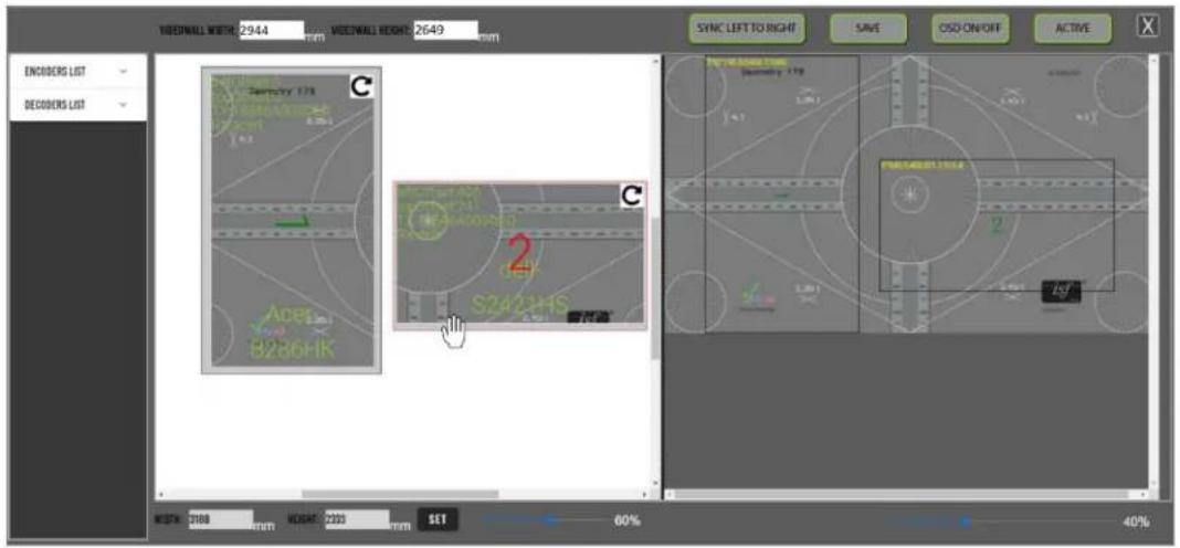
Measurement example:
236mm + 5mm (Dell top bezel) = 241mm
381 (Acer height) + 15 (Acer top bezel) + 5mm gap + 5mm (Dell left bezel) = 406mm
Red point / Coordinate origin: (0,0)
Black point / Coordinate: (406,241)
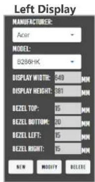
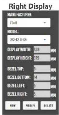
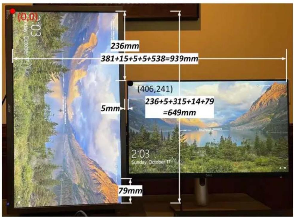
10 Select the encoders list dropdown menu in the left column, this will show a list of all of the encoders with their connected source's preview image as a selectable thumbnail.
11 Select the encoder by clicking and dragging the source's thumbnail, moving it over to the right, and dropping it onto a panel.
The selected source's custom name will now appear in the top-left corner of the panel, indicating that source is now assigned to this display. Repeat this step for other panels.
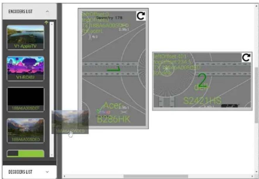
12 Select the decoders list dropdown menu, this will show a list of all of the decoders as selectable buttons. Select the decoder by clicking and dragging the decoder, moving it over to the right, and dropping it onto a panel.
The selected display's custom name will now appear in the top-left of the panel, indicating the selected display is now assigned to this panel. Repeat this step for the other panel with the other display's decoder.
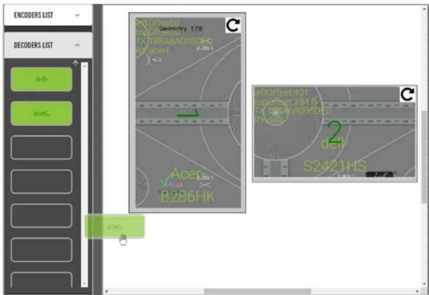
13 Select the save button SAVE followed by the active button ACTIVE located at the top of this page. The final result of the mosaic video wall is shown below:
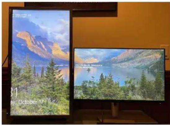
natural_image
Two large screens displaying a scenic mountain landscape with pine trees and a lake, no visible text or symbols on the screens.6.10.5 Creating Another Layout
1 Select the copy to button COPY TO and type in the new layout name, then select the copy videowall layout button COPY VIDEOWALL LAYOUT
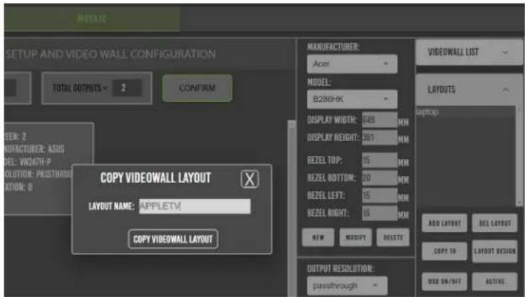
2 Select the layout design button to open the mosaic video wall design window.
3 Drag and drop the new source to the displays from the encoder list, then select the save
SAVE and active ACTIVE buttons located at the top of the page.
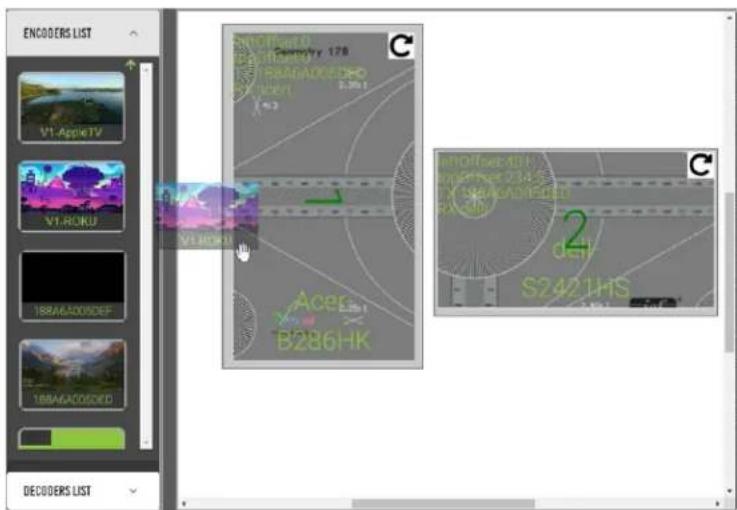
4 To switch mosaic video wall layouts, select the layout name from the Layouts list, then select the active button.
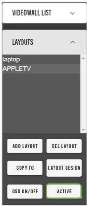
5 To delete a layout, select the layout name from the Layouts list, then select the del layout button DEL LAYOUT. The layout will now be permanently removed from the Layouts list and is no longer able to be activated.
6.11 Central Command
The Central Command page provides tools for creating and building various control commands, including RS-232 over IP, IR over IP, and CEC over IP/HDMI. These commands can be sent to a single encoder or decoder, a specified group of encoders and decoders, or all encoders and decoders.
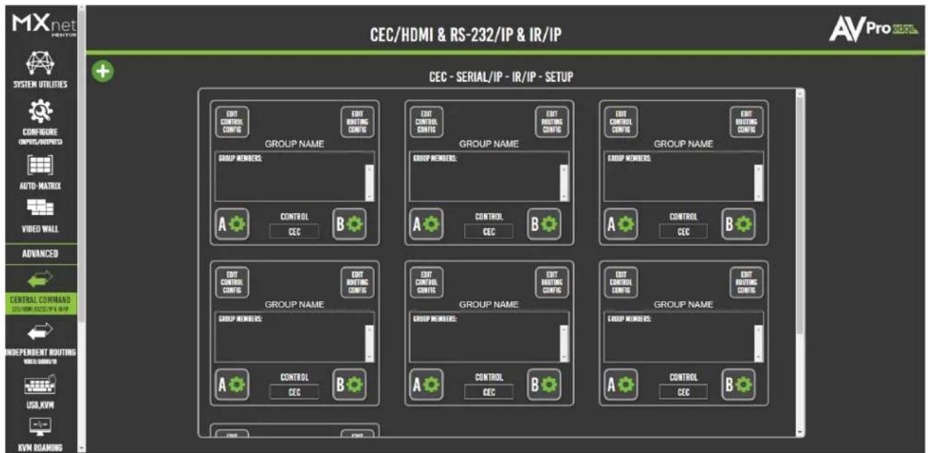
Mentor provides six routing groups for specifying six different sets of targeted display groupings. More routing groups can be added by selecting the + (add) button + in the top-left corner of the page.
Custom commands can be built by selecting the edit control config button and selecting either CEC, RS232/IP, or IR/IP. Each command option will populate the necessary fields for the selected signal type.
6.11.1 Creating a CEC Control Configuration
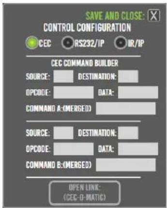
| Source | 1^st Byte, the logical source address of the message |
| Destination 1 | ^st Byte, the logical destination address of the message |
| Opcode | 2^nd Byte, the CEC request message ID |
| Data | 4^th Byte, the local physical address of the HDMI port |
| Command | The HDMI-CEC message in its entirety |
| CEC-O-Matic | Opens a new web browser tab to cec-o-matic.com |
6.11.2 Creating an RS-232 Control Configuration
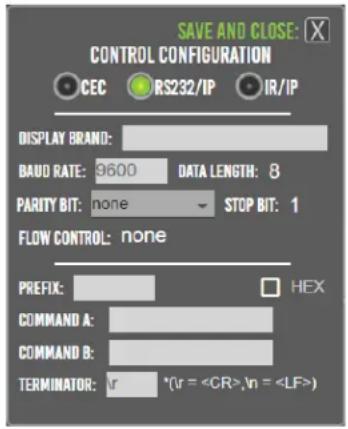
| Display Manufacturer or brand of display | |
| Baud Rate | Speed of bits being sent per second |
| Data Length | Number of bits in a data frame |
| Parity Bit | Error detection, includes none, odd, or even |
| Stop Bit | Allows the next start bit to be transmitted |
| Flow Control | Controls the amount of data being transmitted |
| Prefix | The leading character in each message |
| HEX | Enables HEX characters |
| Command A Specified command | |
| Command B | Specified command |
| Terminator | Carriage return or line feed, may be required by some display manufacturers |
6.11.3 Creating an IR Control Configuration
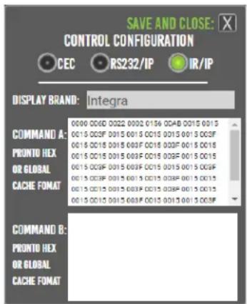
| Display Manufacturer or brand of display | |
| Command A | Specified command |
| Command B | Specified command |
6.11.4 Routing Groups for Encoders and Decoders
Select the edit routing config button, this will open a list of all the encoders and decoders.
Select the sources and displays here to apply the selected control configurations, then select the x button to save and close.
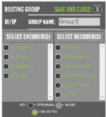
6.12 Independent Routing
This page provides a simple way to separately route video, audio, and control signals from different encoders to different decoders, as well as any equipment connected to either the RS232 or IR EYE and I-PASS ports on the encoders and decoders.
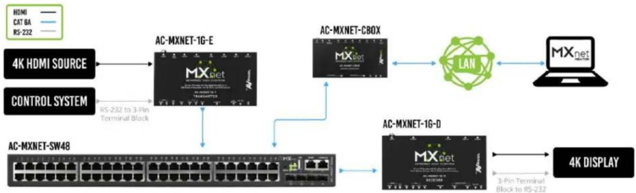
flowchart
graph TD
    A["4K HDMI SOURCE"] --> B["AC-MXNET-1G-E"]
    C["CONTROL SYSTEM"] --> D["AC-MXNET-SW48"]
    B --> E["AC-MXNET-CBOX"]
    D --> F["AC-MXNET-1G-D"]
    E --> G["LAN"]
    F --> H["4K DISPLAY"]
    style A fill:#000,stroke:#fff,color:#fff
    style C fill:#000,stroke:#fff,color:#fff
    style B fill:#999,stroke:#333
    style E fill:#999,stroke:#333
    style F fill:#999,stroke:#333
    style G fill:#ccc,stroke:#333
    style H fill:#ccc,stroke:#333
The routing pages closely resemble the Auto-Matrix page with additional tabs located at the top for separating video, audio, and IR functionality. Each input can be independently configured to route video, audio, and IR signals.
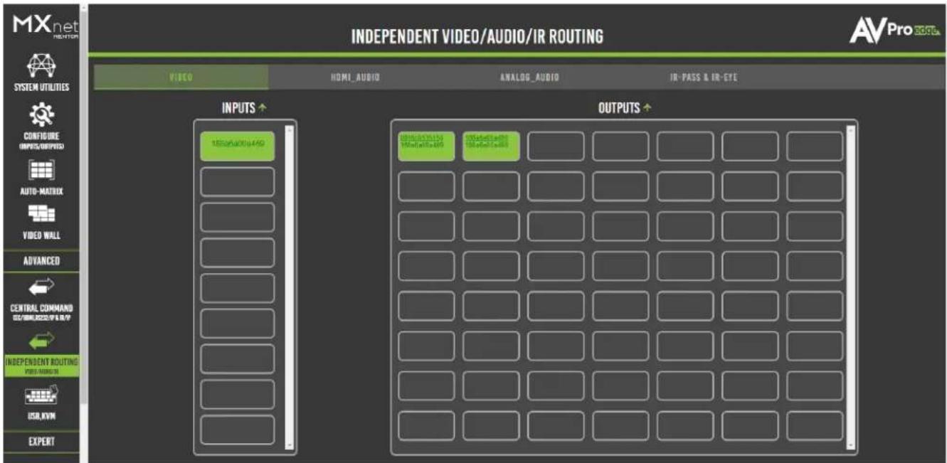
6.12.1 Creating a Routing Path (applies to all tabs)
1 From the Inputs column, select the desired source's input. This will highlight the input with an orange border to indicate the selection was made.
2 From the Outputs grid, select the desired output(s) to route the selected source to. This will highlight the output(s) with an orange border to indicate the selection was made.
3 Switching commands are now sent to the source's encoder and the output's decoder(s), and the selected source's signals will now be present on the selected output(s).
6.13 USB & KVM
The USB & KVM page provides a setup interface for routing any USB 2.0 device that uses the USB ports on the decoder which then provides the input for a keyboard and mouse. The KVM decoder input is then routed directly to the host encoder. For most applications, the host will be a PC type computer with one of its USB ports connected to the encoder's USB HOST port.
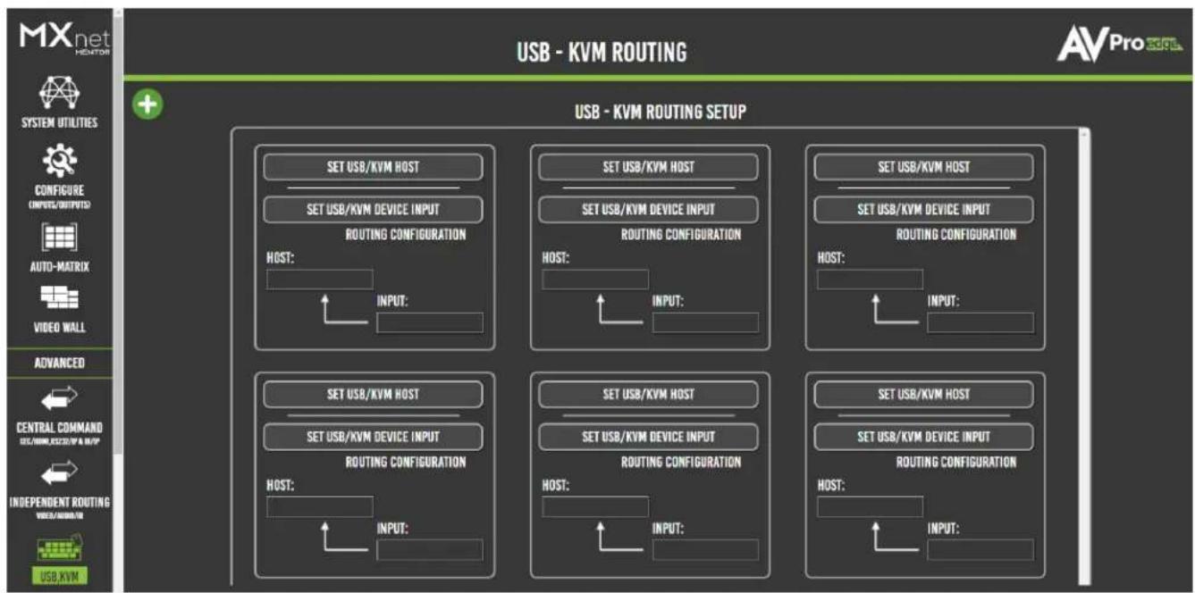
flowchart
graph TD
    A["SET USB/KVM HOST"] --> B["SET USB/KVM DEVICE INPUT"]
    B --> C["ROUTING CONFIGURATION"]
    C --> D["HOST: INPUT"]
    E["SET USB/KVM HOST"] --> F["SET USB/KVM DEVICE INPUT"]
    F --> G["ROUTING CONFIGURATION"]
    G --> H["HOST: INPUT"]
    I["SET USB/KVM HOST"] --> J["SET USB/KVM DEVICE INPUT"]
    J --> K["ROUTING CONFIGURATION"]
    K --> L["HOST: INPUT"]
    M["SET USB/KVM HOST"] --> N["SET USB/KVM DEVICE INPUT"]
    N --> O["ROUTING CONFIGURATION"]
    O --> P["HOST: INPUT"]
    Q["SET USB/KVM HOST"] --> R["SET USB/KVM DEVICE INPUT"]
    R --> S["ROUTING CONFIGURATION"]
    S --> T["HOST: INPUT"]
    U["SET USB/KVM HOST"] --> V["SET USB/KVM DEVICE INPUT"]
    V --> W["ROUTING CONFIGURATION"]
    W --> X["HOST: INPUT"]
    Y["SET USB/KVM HOST"] --> Z["SET USB/KVM DEVICE INPUT"]
    Z --> AA["ROUTING CONFIGURATION"]
    AA --> AB["HOST: INPUT"]
    AC["SET USB/KVM HOST"] --> AD["SET USB/KVM DEVICE INPUT"]
    AD --> AE["ROUTING CONFIGURATION"]
    AE --> AF["HOST: INPUT"]
Mentor provides six routing groups for six different independent routing paths. More routing groups can be added by selecting + (add) button + in the top-left corner of the page.

NOTE:
Chipset V1 decoders (AC-MXNET-1G-D) do not support High-Speed USB 2.0 device connections, while the Chipset V2 decoders (AC-MXNET-1G-DV2) can support one isochronous connection to a High-Speed USB 2.0 device (such as a digital camera) using either USB port 1 or USB port 2 on the V2 decoder.
To check which Chipset version is on a decoder, navigate to the Configure (Inputs/Outputs) page within Mentor and select the Outputs/Decoders/Displays tab. The Chipset column will display the versions of all the decoders.
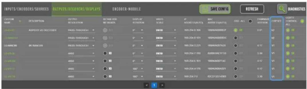
6.13.1 Creating a USB or KVM Routing Path
1 Plug in all the input devices into the USB ports on the decoder and connect the PC to the USB HOST port on the encoder.
2 Select the set usb/kvm host button SET USB/KVM HOST within one of the routing setup boxes. This will open a list of USB host devices for the encoders.

NOTE:
If a previous KVM routing path has already been setup using a different routing setup box, any previously selected encoders will then appear in the list as grey, or unavailable.
3 Select an encoder to set it as the USB host, then select the x button to close the USB host list. The selected encoder will now appear in the host field.
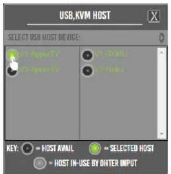
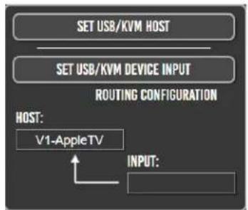
flowchart
graph TD
    A["SET USB/KVM HOST"] --> B["SET USB/KVM DEVICE INPUT"]
    B --> C["ROUTING CONFIGURATION"]
    C --> D["HOST: V1-Apple TV"]
    D --> E["INPUT: "]
4 Select the set usb/kvm device input button SET USB/KVM DEVICE INPUT within the same routing setup box. This will open a list of USB input devices for the decoders.
5 Select a decoder to set it as the USB input device, then select the x button to close the USB host list. The selected decoder will now appear in the input field.
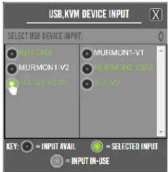
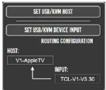
flowchart
graph TD
    A["SET USB/KVM HOST"] --> B["SET USB/KVM DEVICE INPUT"]
    B --> C["ROUTING CONFIGURATION"]
    C --> D["HOST: V1-Apple TV"]
    D --> E["INPUT: TCL-V1-V3.30"]
6.14 KVM Roaming
This page provides tools and features to send bi-directional USB signals for controlling USB and KVM devices up to 150 meters. One KVM roaming group can have up to 17 PCs or laptops, meaning one keyboard and mouse can control up to 17 PCs located in separate secure areas away from the operator running the controls over the network with MXNet. Operators can simply move the mouse cursor across the monitors or screens and fully control that PC through the decoder over the network.
A KVM roaming group consists of a group of decoders that are each connected to their own display (such as a computer monitor or video wall) with one decoder set as the primary decoder and others set as the secondary decoders. In most applications, all PCs or servers will be located in a remote computer rack room and the display monitors and operators will be in the local control rooms or operation centers. In a control room, one operator will operate one KVM roaming group. If there are more operators, then each operator must have a KVM roaming group.
This built-in MXNet feature is ideal for security control rooms, banking networks, corporate communication centers, and educational administration settings.
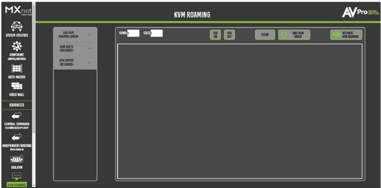
6.14.1 Creating a KVM Array
1 Select the add kvm roaming group dropdown menu, then select the add kvm button ADD KVM.
2 Enter in a name into the kvm name field, and the number of rows and columns, then select the save kvm array button SAVE KVM ARRAY
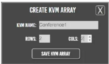
3 The newly created kvm group will now appear under the add kvm roaming group dropdown menu, select this to generate a virtual layout of the specified rows and columns as tiles.
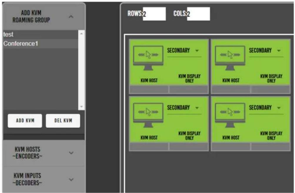
4 Select the kvm hosts encoders dropdown menu, this will show a list of the encoders with their connected source's preview image as a selectable thumbnail.
5 Select the encoder by clicking and dragging the source's thumbnail, moving it over to the right, and dropping it onto a tile.
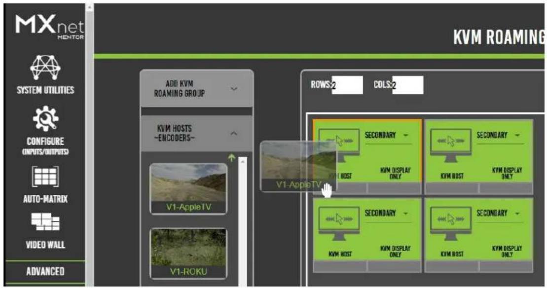
The encoder's custom name will now appear in the bottom-left of the selected tile, indicating the selected source is now assigned as the USB host.
6 Select the kvm inputs decoders dropdown menu, this will show a list of the decoders as selectable buttons.
7 Select the decoder by clicking and dragging the decoder, moving it over to the right, and dropping it onto the same tile.
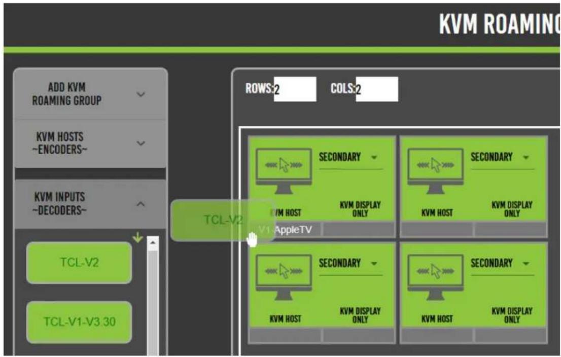
8 The dropdown menu included within each tile can be selected as primary or secondary. Choose primary for main USB hosting devices (such as a desktop PC), and secondary for remote KVM endpoints, (such as a mouse or keyboard connected to a different display).
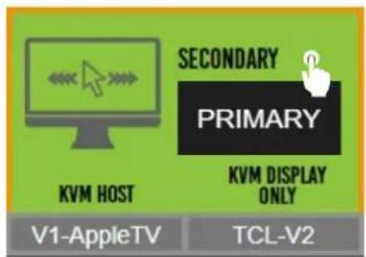
9 (Optional) the OSD on and off buttons can be selected to toggle the OSD overlay to the displays.
6.15 Custom Images
This page provides tools and features for setting up custom logos and images to the displays, ideal for digital signage solutions in a commercial installation. It is separated into two tabs, Fallback Logo and Force Image.
![DECODER ~ CUSTOM FALLBACK IMAGES LOGOS AND FORCE IMAGE AVPro logo FALBACK LOGO FORCE IMAGE REFRESH SAVE CHANGES SELECT ALL DECODERS: TCL-V2 TCL-V1-V3.30 MURMON2-V3.30 MURMON1-V2 MURMON1-V1 INTEGRA FALBACK LOGO BOOT/STARTUP IMAGE IMAGE REHINDMENTS 1.BMP image format with 16 bit(RGB565) color,or 32 bit(RGB8888)color. 2.[NOTE: 16 bit(RGB555),and 24 bit(RGB888) color formats will not work.] 3.MAXIMUM FILE SIZE = 130K. 4.RESOLUTION MUST BE 640x480. 5.For best results,use a solid background color. "NO SIGNAL" IMAGE IMAGE REHINDMENTS 1.JPEG 2.MAXIMUM FILE SIZE = 99K. UPDATE RESET / RESET RESET IMAGE UPDATE RESET / RESET RESET IMAGE](/content/2026/05/987212/images/7f2b4e61e49a0a26d810966870fa8f3bd52157136597adbe61c15c59a23538d1.jpg)
6.15.1 Fallback Logo
The Fallback Logo page provides options and settings for uploading a custom image to appear on selected displays upon initial startup after a reboot or when a device is disconnected from a decoder.
Image Requirements:
BOOT/STARTUP IMAGE
- BMP file format
• 16-bit (RGB656) color, or 32-bit (RGB8888) color
• 130KB maximum file size - 640 x 480 pixel resolution
"NO SIGNAL" IMAGE
- JPEG file format
• 99KB maximum file size
If no custom images are uploaded, Mentor will display the following default image:

6.15.2 Uploading a Fallback Logo or "No Signal" Image
1 Select the display from the list of decoders on the left side, indicated by a highlighted orange border. To send the custom image to all the displays, check the select all decoders box SELECT ALL PROCESERS
2 Select the paperclip icon ☐ to browse through local files and select the desired image file.
3 Select the update button UPDATE to upload the selected file image to the selected display(s). Then select the save changes button SAVE CHANGES.
6.15.3 Force Image
This tab provides tools and features that allow the displays to switch to a custom image or logo for more personalized media content.
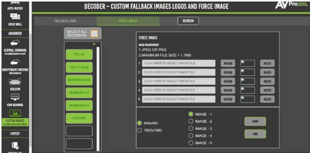
Image Requirements:
BOOT/STARTUP IMAGE
- JPEG or PNG file format
• 1.7MB maximum file size
6.15.4 Uploading a Force Image
1 Select the display(s) from the list of decoders on the left side, indicated by a highlighted orange border. To send the custom image to all the displays, check the select all decoders box SELECT ALL DECODEERS
2 Select one of the fields, numbered 1-5, to browse through the local files and select the desired image file. Up to 5 images can be uploaded at a time.
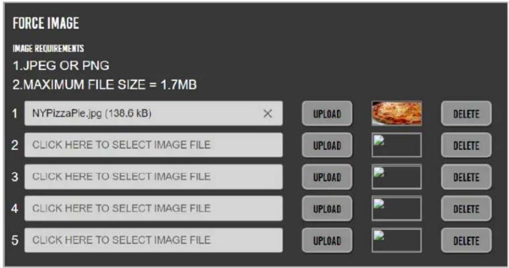
3 Select the upload button 📋, a thumbnail will generate a preview of the selected image.
4 Select the desired resolution, the image number, followed by the show button.
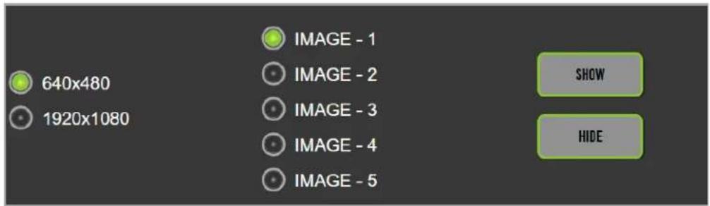
5 The uploaded image will now be shown on the selected display(s).
6 To remove a forced image, select the hide button
6.16 System Log
MXNet Mentor features the System Log page that provides current MXNet system information, time zone options for the system time and date, and setting NTP (Network Time Protocol) servers for more precise signaling and time synchronization.
![[DEBUG 2022-10-05 03:53:23] Command: {"cmd":"config get timezone"} [DEBUG 2022-10-05 03:53:23] Response: {"info":"UTC+0",cmd":"{\cmd}\\`\config get timezone\"}"] [DEBUG 2022-10-05 03:53:23] POST /do 200 [DEBUG 2022-10-05 03:53:24] Command: {"cmd":"config get date"} [DEBUG 2022-10-05 03:53:24] Response: {"info":"2022-10-05 03:53:24",cmd":"{\cmd}\\`\config get date\"}"] [DEBUG 2022-10-05 03:53:24] POST /do 200 [DEBUG 2022-10-05 03:53:25] Command: {"cmd":"config get ntp"} [DEBUG 2022-10-05 03:53:25] Response: {"info":"0.us.pool.ntp.org/1.us.pool.ntp.org/2.us.pool.ntp.org/3.us.pool.ntp.org",cmd":"{\cmd}\\`\config get ntp\"}] [DEBUG 2022-10-05 03:53:25] POST /do 200 [DEBUG 2022-10-05 03:53:28] GET /video_mosaic?t=1664901936812 301 [DEBUG 2022-10-05 03:53:29] GET /video_mosaic?t=1664901936812/ 304 [DEBUG 2022-10-05 03:53:40] GET / 304 Set Time System Time: 2022-10-05 3:53:56 Year Month Day 2022 - 10 - 05 Hour Minute Second 3 - 53 - 24 SET Time Zones: UTC+0 UTC+0 SET Set NTP Server 0.us.pool.ntp.org 1.us.pool.ntp.org 2.us.pool.ntp.org 3.us.pool.ntp.org SET](/content/2026/05/987212/images/debc1d165db5b8a607a0aa3c3e3653c44d9e7fb7c31d100ecd542ecace85a289.jpg)
1 SYSTEM LOG SCREEN
This is the MXNet log that records system events generated by the AC-MXNET-CBOX in a continuous stream while the page is open within Mentor. Events recorded in the System Log consist of timestamped information about commands, system functions, and what actions were taken. Users cannot alter the recorded information logged by the System Log page.

NOTE:
The System Log only records information while Mentor is opened to the System Log page and does not record and store information internally.

TIP:
Open the System Log page in a separate tab on your web browser to record information while testing or troubleshooting Mentor on a different web browser tab.
2 KEYWORD SEARCH
Dropdown menu containing search options for locating specific information in the current running system log. Keywords or phrases can be searched by selecting one of the dropdown menu options, typing in the keyword or phrase into the text field, and selecting the search button on the right.
Keyword Search locates all information containing the specific keyword or phrase within the System Log.
Keyword Filtering hides all information containing the specific keyword or phrase within the System Log.
3 SEARCH FIELD
Type in a keyword or phrase into the text field then select the search button to locate or hide all the information containing the keyword or phrase from the System Log screen.
4 VIEW SETTINGS
Selecting one of these buttons alters how the information is viewed on the System Log screen.
All shows all information of events currently recorded while the page is open within Mentor.
Clear hides all events recorded in the System Log from view.
Export Log downloads a .txt file of all System Log events recorded up until the page opened within Mentor.
5 SET TIME
The System Time is set by the default NTP server(s). If there are no NTP servers set within Mentor, the System Time can be manually entered in by typing into the date and time fields and selecting the set button SET to apply the changes.
6 TIME ZONES
Select the dropdown menu to set the UTC time zone to a positive or negative UTC offset, then select the set button SET to apply the changes.
7 SET NTP SERVER
By default, MXNet utilizes these four NTP servers from United States – us.pool.ntp.org:
0.us.pool.ntp.org
1.us.pool.ntp.org
2.us.pool.ntp.org
3.us.pool.ntp.org
The servers are listed by priority level, meaning that the System Time will always be set by the NTP server listed in the first field. Should the first NTP server fail, then the System Time will be set by the second listed NTP server, and so on.
Up to 5 NTP servers can be set by entering in the NTP server addresses into the fields and selecting the set button SET to apply the changes.
7 MAINTENANCE
To ensure reliable operation of these devices as well as protecting the safety of any person using or handling these devices while powered, observe the following instructions:
- Use the provided power supplies. If an alternative power supply is required, check the voltage and polarity to ensure it has sufficient power to supply the device it is connected to.
- Do not operate these devices outside the specified temperature and humidity range given in the above specifications.
- Ensure there is adequate ventilation to allow these devices to operate efficiently.
- Repair of the equipment should only be carried out by qualified professionals as these devices contain sensitive components that may be damaged by any mistreatment.
- Only use these devices in a dry environment. Do not allow any liquids or harmful chemicals to come into contact with these devices.
- Clean this unit with a soft, dry cloth. Never use alcohol, paint thinner, or benzene to clean these devices.
8 DAMAGE REQUIRING SERVICE
The devices should be serviced by qualified personnel if:
- The DC power supply cord or AC adapter has been damaged
- Objects or liquids have breached the interior of the devices
- The devices have been exposed to rain or moisture
- The devices do not operate normally or exhibit a marked change in performance
- The devices have been dropped or the housing is damaged
9 SUPPORT
Should you experience any problems using this product, you may contact AVPro Technical Support. When calling in, the following information should be provided:
• Product name and model number
• Product serial number
• Details of the issue and any conditions under which the issue is occurring
10 WARRANTY
10.1 The Basics
AVPro Edge warranties its products that are purchased from all authorized AVPro Edge resellers or direct purchases. Products are guaranteed to be free from manufacturing defects and are of sound physical and electronic condition.
AVPro Edge has developed a warranty that anyone can get behind. We really wanted to take all the "red tape" out of a warranty and just make it simple. Our 10 Year No BS Warranty hinges on 3 elements:
- If you are having trouble, call us. We will attempt to troubleshoot your issue over the phone.
- If it's broken, we will replace it in advance on our dime and we'll also cover the return shipping. Repair is an option too, but it's YOUR call.
- We know you know what you are doing. We will not make you go through unnecessary steps to troubleshoot an extender.
10.2 Coverage Details
AVPro Edge will replace or repair (at customer choice) defective products. If the product is out of stock or on backorder it can be replaced with a comparable product of equal value/feature set (if available) or repaired.
Your warranty begins at receipt of product (as confirmed by shipping firm tracking). If tracking information is unavailable for any reason, the warranty will commence 30 ARO (After Receipt of Order). The coverage continues for 10 years.
10.3 Red Tape
AVPro Edge is not responsible for untraceable purchases or those that were made outside of an authorized channel.
If we conclude that a product or serial number has been tampered with as identified by warranty seal of physical examination the warranty will be void. Additionally, excessive physical damage (beyond normal wear & tear) the warranty may be voided or prorated based on the extent of the damage as examined by an AVPro Edge representative.
Damage caused by “acts of God” are not covered. They include natural disasters, power surges, storms, earthquakes, tornadoes, sink holes, typhoons, tidal waves, hurricanes, or any other uncontrollable event related to nature.
Damage caused by incorrect installation will not be covered. Incorrect power supply, inadequate cooling, improper cabling, inadequate protection, static discharge are examples of this.
Products installed or sold by a third party to AVPro Edge will be serviced by the authorized AVPro Edge reseller. Accessories (IR cables, RS-232, power supplies, etc.) are not included in the warranty. We will make acceptable efforts to source and supply replacements for defective accessories at a discounted rate as needed.
10.4 Obtaining an RMA
Dealers, resellers, and installers can request an RMA from an AVPro Edge Technical Support representative or Sales Engineer. Or you may email support@avproedge.com or fill out the general contact form at www.avproedge.com/contact.
End users may not request an RMA directly from AVPro Edge and will be referred back to the dealer, reseller, or installer.
10.5 Shipping
For USA (not including Alaska and Hawaii), shipping is covered on advanced replacements for FedEx Ground (some expressed exceptions may apply). Defective product return shipping is covered by
AVPro Edge using an emailed return label. Items must be returned with 30 days of receipt of the replacement product, after 40 days the customer will be billed. Other return shipping methods will not be covered.
For international (and Alaska and Hawaii) return shipping costs will be the responsibility of the returnee. Once the unit is scanned for return shipping AVPro Edge will ship the new replacement unit.
10.6 Limitation on Liability
The maximum liability of AVPro Global Holdings LLC under this limited warranty shall not exceed the actual purchase price paid for the product. AVPro Global Holdings LLC is not responsible for direct, special, incidental, or consequential damages resulting from any breach of warranty or condition, or under any other legal theory to the maximum extent permitted by law. Taxes, Duties, VAT, and other freight forwarding service charges are not covered or paid for by this warranty.
Obsolescence or incompatibility with newly invented technologies (after manufacture of product) is not covered by this warranty. Obsolescence is defined as:
"Peripherals are rendered obsolete when current technology does not support product repair or remanufacture. O products cannot be remanufactured because advanced technologies supersede original product manufacturer capabilities. Because of performance, price and functionality issues, product re-development is not an option."
Discontinued or out-of-production items will be credited at fair market value towards a current product of equal or comparable capabilities and cost. Fair market value is determined by AVPro Edge.
10.7 Exclusive Remedy
To the maximum extent permitted by law, this limited warranty and the remedies set forth above are exclusive and in lieu of all other warranties, remedies, and conditions, whether oral or written, express or implied. To the maximum extent permitted by law, AVPro Global Holdings LLC specifically disclaims any and all implied warranties, including, without limitation, warranties of merchantability and fitness for a particular purpose. If AVPro Global Holdings LLC cannot lawfully disclaim or exclude implied warranties under applicable law, then all implied warranties covering this product, including warranties of merchantability and fitness for a particular purpose, shall apply to this product as provided under applicable law.
This warranty supersedes all other warranties, remedies, and conditions, whether oral or written, express or implied.
- IMPORTANT SAFETY INSTRUCTIONS
- Electrical Shock Prevention
- ELECTRICAL SHOCK:
- ELECTRICAL DISCONNECT:
- Weight Injury Prevention
- WEIGHT INJURY:
- Safety Statements
- INTRODUCTION
- Descriptions
- Encoders and Decoders
- MXNet 1G Evolution II
- IMPORTANT:
- Audio Downmixing
- Control
- Mentor
- Network Switches
- Before You Begin
- Some Helpful Suggestions
- Network Cabling Tips
- Recommended Best Practices
- Third-Party Control Systems
- THIRD-PARTY NETWORK SWITCH REQUIREMENTS
- IGMPv2 Snooping
- IGMPv2 Querier
- IGMPv2 Immediate-Leave
- Unknown Multicast Dropping (or Unregistered Multicast Flooding)
- MTU Settings
- PoE Budget
- Disabling EEE
- PRODUCT OVERVIEW
- Box Contents and Specifications
- AC-MXNET-1G-E / AC-MXNET-1G-E-AVDM / AC-MXNET-1G-EV2
- AC-MXNET-1G-EWP
- AC-MXNET-1G-D / AC-MXNET-1G-DV2
- AC-MXNET-CBOX
- AC-MXNET-SW10
- AC-MXNET-SW24
- AC-MXNET-SW48
- WIRING AND CONNECTIONS
- 1G Ethernet/LAN
- AV NETWORK
- SFP and SFP+ Transceiver Modules
- NOTE:
- Compatible SFP and SFP+ Transceiver Modules Specifications for MXNet Network Switches
- SFP
- SFP+
- Installing SFP and SFP+ Transceiver Modules
- TIP:
- WARNING:
- Short Reach (SR) SFP or Long Reach (LR) SFP
- DAC Cables
- HDMI Cables
- USB Ports
- RS-232 Wiring
- IR Wiring
- Analog Audio Ports
- AC Power Connection
- INSTALLATION
- Connecting the Devices
- Point-to-Point Setup
- Configuring Encoders and Decoders
- Stacking Switches
- THE MENTOR WEB UI
- Accessing Mentor
- Navigating the Mentor Web UI
- System Utilities
- LAN and AV Network Configurations
- MXNET SYSTEM CONTROL - MENTOR/LAN PORT
- MXNET AV/IP NETWORK POE PORT
- MXNet Firmware Updates
- MXNet Events
- MXNET SYSTEM EVENTS (system-wide)
- MXNET DEVICE EVENTS (device specific)
- USER MANAGEMENT
- Configure Inputs and Outputs
- INPUTS/ENCODERS/SOURCES
- OUTPUTS/DECODERS/DISPLAYS
- ENCODER-MODULE (for AVDM Encoders only)
- SAVE CONFIG
- REFRESH
- DIAGNOSTICS
- Inputs/Encoders/Sources
- CUSTOM NAME (default MAC address)
- DESCRIPTION
- EDID MGMT
- CHANNEL
- IP ADDRESS (auto)
- MAC ADDRESS (auto)
- FIRMWARE VERSION
- CHIPSET
- LIGHTS CONTROL
- Outputs/Decoders/Displays
- OUTPUT RESOLUTION
- RETAIN HDR METADATA
- DISPLAY ROTATION
- VIDEO SCALE
- IP ADDRESS (auto)
- MAC ADDRESS (auto)
- OSD (Onscreen Display)
- FIRMWARE VERSION
- Encoder Module (AVDM Encoders only)
- TYPE
- CUSTOM NAME
- DESCRIPTION
- ENCODER MAC ADDRESS
- ENCODER CUSTOM NAME
- FIRMWARE VERSION
- MODE
- System Diagnostics
- CUSTOM NAME
- SWITCH PORT NUMBER
- REAL TIME BANDWIDTH (Mbps)
- POE
- DESCRIPTION
- NETWORK CONNECTION
- CONNECTION SPEED
- BANDWIDTH SETTINGS (Encoders only)
- HOT-PLUG DETECT/RESET
- HDCP VERS
- ENCODER/DECODER LIGHTS
- TEST PATTERN
- CONNECTED SINK/DISPLAY
- SOURCE ENCODERS
- Auto-Matrix
- Inputs
- Outputs
- Matrix Switching
- Matrix Presets
- Creating a Preset
- Activating a Preset
- Deleting a Preset
- Video Wall
- Standard Layout
- Mosaic-Style Layout
- Creating a Video Wall Array
- Creating a Mosaic Video Wall
- Creating Another Layout
- Central Command
- Creating a CEC Control Configuration
- Creating an RS-232 Control Configuration
- Creating an IR Control Configuration
- Routing Groups for Encoders and Decoders
- Independent Routing
- Creating a Routing Path (applies to all tabs)
- USB & KVM
- Creating a USB or KVM Routing Path
- KVM Roaming
- Creating a KVM Array
- Custom Images
- Fallback Logo
- BOOT/STARTUP IMAGE
- "NO SIGNAL" IMAGE
- Uploading a Fallback Logo or "No Signal" Image
- Force Image
- Uploading a Force Image
- System Log
- SYSTEM LOG SCREEN
- KEYWORD SEARCH
- SEARCH FIELD
- VIEW SETTINGS
- SET TIME
- TIME ZONES
- SET NTP SERVER
- MAINTENANCE
- DAMAGE REQUIRING SERVICE
- SUPPORT
- WARRANTY
- The Basics
- Coverage Details
- Red Tape
- Obtaining an RMA
- Shipping
- Limitation on Liability
- Exclusive Remedy
Brand : AVPro Edge
Model : MXNet AC-MXNET-1G-AVDM
Category : NAS