LSP-SCS/B - Uncategorized Impact - Free user manual and instructions
Find the device manual for free LSP-SCS/B Impact in PDF.


| Brand | Impact |
| Model | LSP-SCS/B |
| Product Type | Studio Column Stand with Sliding Arm |
| Load Capacity | 17.6 lb (8 kg) |
| Maximum Working Height | 7.25 ft (2.2 m) |
| Collapsed Height | 40.5 in (102.7 cm) |
| Footprint Diameter | 42 in (106.7 cm) |
| Weight (with sliding arm) | 19.7 lb (8.9 kg) |
| Material | Anodized aluminum and steel |
| Finish | Black Chrome / Black |
| Mounting Options | 5/8 in stud, 1/4-20 male thread |
| Sliding Arm | Spring-loaded with pistol grip brake, length 10.5 in (26.7 cm) |
| Column Extension Length | 42 in (106.7 cm) |
| Wheels | 3-inch locking wheels included |
| Leveling Leg | Yes, adjustable with hex key |
| Included Accessories | Carry bag, hex key, reversible stud |
| Safety | Use steel safety cable (not included); do not exceed load capacity; keep away from children |
| Maintenance | Clean with dry cloth; use only manufacturer-provided parts |
| Warranty | One-year limited warranty |
Frequently Asked Questions - LSP-SCS/B Impact
User questions about LSP-SCS/B Impact
0 question about this device. Answer the ones you know or ask your own.
Ask a new question about this device
Download the instructions for your Uncategorized in PDF format for free! Find your manual LSP-SCS/B - Impact and take your electronic device back in hand. On this page are published all the documents necessary for the use of your device. LSP-SCS/B by Impact.
USER MANUAL LSP-SCS/B Impact
Thank you for choosing Impact.
The Impact LSP-SCS/B Studio Column Stand with Sliding Arm offers an effective solution for swiftly and effortlessly moving and adjusting one or more light ☐xtures around the set. The spring-loaded sliding arm is easily operated, and it provides sturdy support for ☐xtures weighing up to 17.6 pounds. The sliding arm can be positioned anywhere along the column at the maximum height of 7.25 feet or almost at ☐oor level, which is great for all varieties of standing or sitting portraits. Three-inch locking wheels easily roll on most surfaces, including carpeting. A leveling leg helps straighten out the center column on slight inclines. The LSP-SCS/B is an ideal light stand to use in offices or rooms with drop ceilings. An included reversible stud provides mounting options for lights with 5/8-inch receivers as well as ball heads, LEDs, or ☐ashes with 1/4-20 mounting sockets.
Precautions ⚠️
- Please read and follow these instructions, and keep this manual in a safe place.
-
Use only parts provided by the manufacturer.
• Make sure everything is secure before proceeding.
• Always use a steel safety cable (not included) when suspending a light fixture or other assembly.
• Make sure that this product is intact and that there are no missing parts. -
Do not exceed the maximum load capacity.
- Keep this product away from children.
- Use caution when using this product with the maximum load capacity.
- Do not push the bridge all the way inside the main column.
• All images are for illustrative purposes only.
Overview
- Extension column
- Bridge
- Reversible stu d
- Locking knob
- Sliding arm
- Cable clip
- Hex key
- Main column and legs
- Locking whee Is (×3)
Also Included
- Carry bag
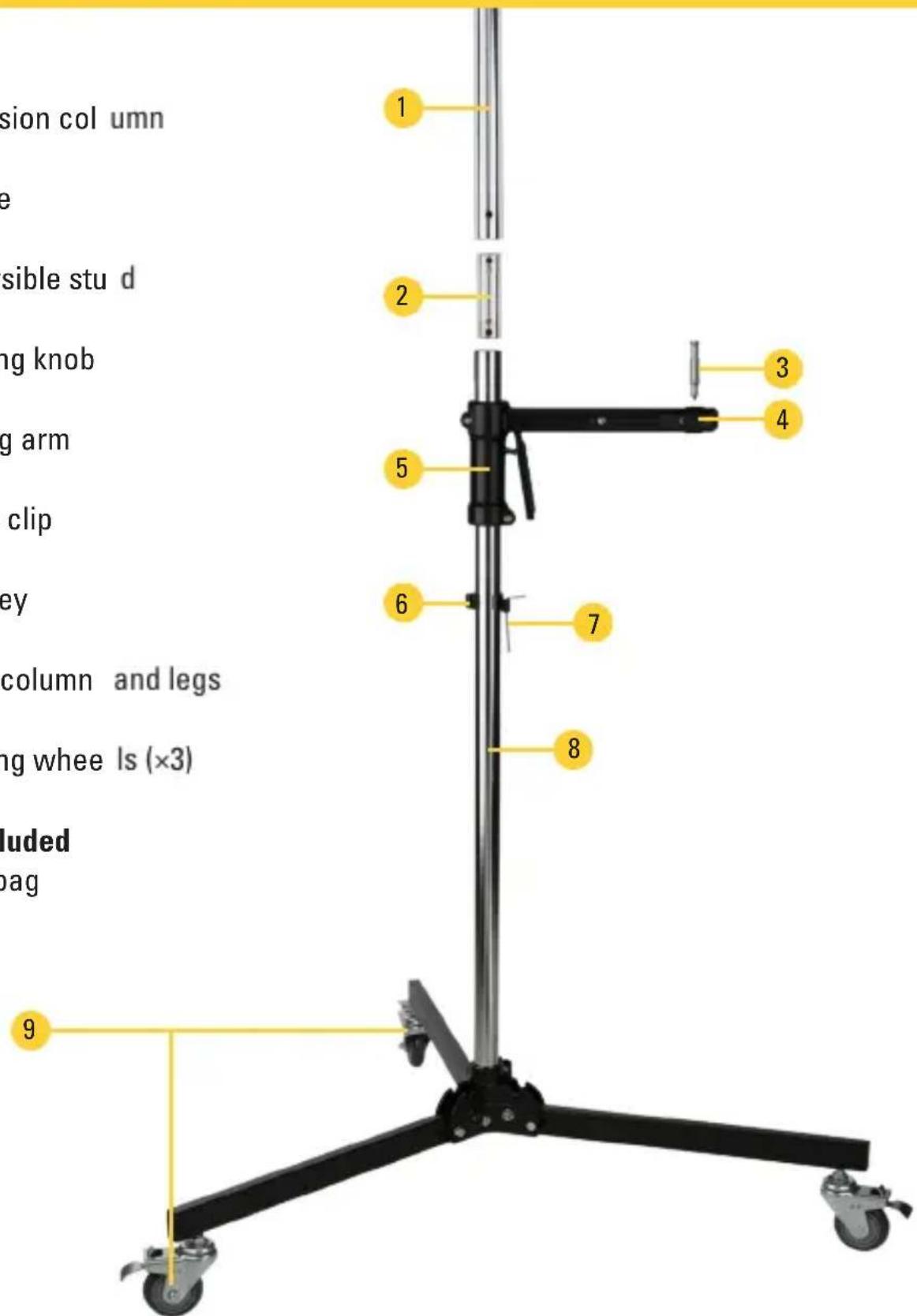
Setup
Attaching the Wheels and Setting the Legs
- Make sure the wheel locks are in the locked position by pressing down on the tab marked "On."
- Once the wheels are locked, screw them into the legs.
- Pull the spring-loaded leg locks to free the legs, and unfold the legs until they lock into place.
For uneven surfaces, adjust the leveling leg screw by inserting a hex key or a screwdriver into the hole and turning to adjust the leg height until the base is stable.
Once the wheels are attached, the wheel locks can be operated by foot. To unlock the wheels, step on the Off tab at the top of each wheel. Lock the wheels by stepping down on the On tab.
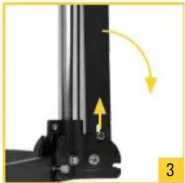
natural_image
Close-up of a mechanical assembly with yellow directional arrows indicating motion or force (no text or symbols)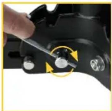
natural_image
Close-up of a hand using a wrench to adjust a mechanical component with circular arrows indicating rotation (no text or symbols visible)Assembling the Stand
- Squeeze the pistol grip and slide the arm over the main column. Release the pistol grip to engage the brake. Slide it down far enough so it doesn't obstruct the hole in the main column.
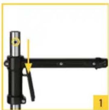
natural_image
Mechanical lever assembly diagram showing a black shaft and lever with a yellow arrow indicating motion direction (no text or symbols)-
Press the two sides of the bridge together and insert it into the main column. Make sure the set screw is aligned with the hole in the main column. Use the hex key to tighten the set screw until secure.
-
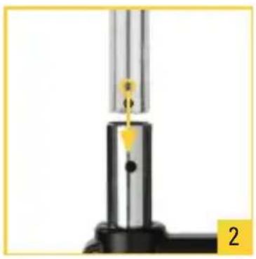
Align the hole in the column extension with the set screw on the bridge. Insert the extension over the bridge, and tighten the set screw with the hex key.
-
Loosen the locking knob on the sliding arm, and insert the pin. Tighten the lock until secure. Note: The pin has a milled flat surface to prevent it from twisting in the mount. Make sure the flat side of the pin faces the lock.
To mount a ballhead or other fixture on the arm, reverse the pin by inserting the 5/8-inch end into the receiver so the 1/4-20 screw is exposed.
natural_image
Close-up of a mechanical testing setup with a vertical rod and base, no visible text or symbols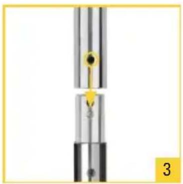
natural_image
Close-up of a mechanical component with a yellow arrow indicating direction, no visible text or symbols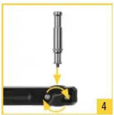
natural_image
Mechanical assembly diagram showing a cylindrical tool inserted into a black component with a circular motion indicator (no text or symbols)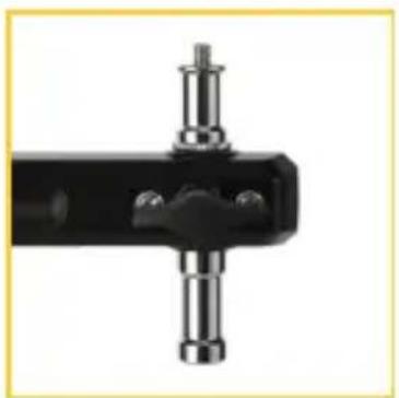
natural_image
Close-up of a black mechanical clamp or bracket with metallic pins and mounting holes (no text or symbols visible)Specifications
| Load Capacity 17.6 lb. (8 kg) | |
| Mounting Options 5/8 in. stud | 1/4-20 male thread |
| Number of Sections 2 | |
| Column Diameter 35 mm | |
| Maximum Working Height 7.25 ft. (2.2 m) | |
| Max Height w/o Extension 45 in. (114.3 cm) | |
| Collapsed Height 40.5 in. (102.7 cm) | |
| Footprint Diameter 42 in. (106.7 cm) | |
| Pistol Grip Length 10.5 in. (26.7 cm) | |
| Column Extension Length 42 in. (106.7 cm) | |
| Leg Shape Rectangle | |
| Accepts Wheels Included | |
| Leveling Leg Yes | |
| Finish LSP-SCS: Chrome/Black | LSP-SCSB: Black Chrome/Black |
| Material Anodized aluminum and steel | |
| Weight | 19.7 lb. (8.9 kg) with sliding arm |
One-Year Limited Warranty
This Impact product is warranted to the original purchaser to be free from defects in materials and workmanship under normal consumer use for a period of one (1) year from the original purchase date or thirty (30) days after replacement, whichever occurs later. The warranty provider's responsibility with respect to this limited warranty shall be limited solely to repair or replacement, at the provider's discretion, of any product that fails during normal use of this product in its intended manner and in its intended environment. Inoperability of the product or part(s) shall be determined by the warranty provider. If the product has been discontinued, the warranty provider reserves the right to replace it with a model of equivalent quality and function.
This warranty does not cover damage or defect caused by misuse, neglect, accident, alteration, abuse, improper installation or maintenance. EXCEPT AS PROVIDED HEREIN, THE WARRANTY PROVIDER MAKES NEITHER ANY EXPRESS WARRANTIES NOR ANY IMPLIED WARRANTIES, INCLUDING BUT NOT LIMITED TO ANY IMPLIED WARRANTY OF MERCHANTABILITY OR FITNESS FOR A PARTICULAR PURPOSE. This warranty provides you with specific legal rights, and you may also have additional rights that vary from state to state.
To obtain warranty coverage, contact the Impact Customer Service Department to obtain a return merchandise authorization (“RMA”) number, and return the defective product to Impact along with the RMA number and proof of purchase. Shipment of the defective product is at the purchaser’s own risk and expense.
For more information or to arrange service, visit www.impactstudiolighting.com or call Customer Service at 212-594-2353.
Product warranty provided by the Gradus Group.
www.gradusgroup.com
Impact is a registered trademark of the Gradus Group. © 2020 Gradus Group LLC. All Rights Reserved.

IMPACT®
A Gradus Group Brand
Brand : Impact
Model : LSP-SCS/B
Category : Uncategorized