
Thunder TH2500.1 - Receiver MTX Audio - Free user manual and instructions
Find the device manual for free Thunder TH2500.1 MTX Audio in PDF.


| Product Type | Monoblock Class-D Amplifier |
| Model | Thunder TH2500.1 |
| Brand | MTX Audio |
| RMS Power Output (1 Ohm) | 2500W |
| RMS Power Output (2 Ohm) | 1750W |
| RMS Power Output (4 Ohm) | 1000W |
| Total Harmonic Distortion | < 0.1% |
| Signal-to-Noise Ratio | > 100dB |
| Input Sensitivity | 200mV - 10V |
| Low Pass Crossover Frequency | 50Hz - 250Hz |
| Subsonic Filter | 10Hz - 55Hz |
| Bass Boost | 0dB - 12dB @ 45Hz |
| Phase Switch | 0° / 180° |
| Recommended Fuse Rating | 250A - 300A |
| Recommended Power/Ground Wire | 1/0 AWG |
| Maximum Speaker Wire Gauge | 4 AWG |
| Dimensions (H x W x D) | 2" x 14.5" x 7" (50mm x 367mm x 176mm) |
| Protection Circuitry | Short Circuit, Thermal, Under/Over Voltage, DC Offset |
| Remote Bass Control (EBC) | Included |
| LED Indicators | Power (red), Protect (red), Clip (blue) |
| Package Contents | Amplifier, EBC Remote, Manual, Mounting Screws, Allen Wrenches |
Frequently Asked Questions - Thunder TH2500.1 MTX Audio
User questions about Thunder TH2500.1 MTX Audio
0 question about this device. Answer the ones you know or ask your own.
Ask a new question about this device
Download the instructions for your Receiver in PDF format for free! Find your manual Thunder TH2500.1 - MTX Audio and take your electronic device back in hand. On this page are published all the documents necessary for the use of your device. Thunder TH2500.1 by MTX Audio.
USER MANUAL Thunder TH2500.1 MTX Audio
natural_image
Exterior view of a metallic industrial electronic device labeled 'MX' (no additional text or symbols visible)TH750.1 / TH1500.1 / TH2500.1
TH400.4 / TH800.4
TH1400.5 / TH900.6
INTRODUCTION
Congratulations on the purchase of your new MTX gear. For over 50 years MTX remains an American family-owned manufacturer full of passionate enthusiasts just like you. Thank you for counting on us to help you "Amplify The Ride"!
For best performance and longevity of your audio gear, we recommend you have your new MTX product installed by an Authorized MTX Dealer. Their installation knowledge and expertise will ensure you get the most out of your new equipment while safeguarding against potential issues. Also, please read your product warranty carefully and retain your receipt and original carton for possible future use.
We're here to help with any installation or technical support. Visit www.mtx.com to chat, call 1-800-225-5689 to speak with an MTX Technical Support representative, or visit www.youtube.com/user/MTXAudioUSA to view product videos.
Don't forget to register your new MTX product. Visit www.mtx.com/productregistration or scan the QR code below.
Model # ____
Serial # ____
Dealer's Name ____
Date of Purchase ____

TABLE OF CONTENTS
- Introduction / Safety
- Features / Package Contents
- Control Functions
- Installation
11.Wiring
15.Dimensions - Specifications
19.Warranty
SAFETY
- Please read and follow these instructions to prevent injury and damage to the unit.
- If you are unsure about installing the system by yourself, please have it installed by a qualified MTX technician.
- Whenever working on the vehicle, it is recommended to disconnect the battery prior to starting work. Failure to do so may lead to a risk of electric shock or equipment damage. When connecting power and ground wires ensure that the power wire is fused at the point where it is connected to the vehicle's battery. Failure to do so can result in damage to the vehicle if a short circuit develops between the vehicle connection point and the product.
WARNING: This symbol with "WARNING" is intended to alert the user to the presence of important operating and maintenance (servicing) instructions in the literature accompanying the product.
CAUTION: This symbol with "CAUTION" is intended to alert the user to the presence of important operating and maintenance (servicing) instructions in the literature accompanying the product.
FEATURES
- Reliable and Efficient Class-D Circuit Design
- Small Size Footprint for Easy Installation
• Surface Mount Component Technology - Direct Insert Power and Speaker Terminals
• Protection and Clip LED Light Status Indicators - Short, Thermal, and Under / Over Voltage Protection
• DC Offset Auto Turn On
PACKAGE CONTENTS
• (1) THUNDER Series Amplifier
• (1) EBC Remote Knob (Not Included with TH400.4, TH800.4, and TH900.6 Models)
• (1) Manual
• (4) Mounting Screws
• (2) Allen Wrenches, (3) for TH2500.1

natural_image
Abstract geometric logo design with interlocking angular shapes (no text or symbols)CONTROL FUNCTIONS
-
Gain Control - The gain control matches the input sensitivity of the amplifier to the source unit being used. The operating range is 200mv to 10V.
-
RCA Inputs - The RCA inputs accept signal from either low-level (RCA) or high-level (speaker) inputs up to 10V. Source units need a minimum 200mV output for proper operation of the amplifier.
-
Power LED - The Power LED illuminates red when the amplifier is powered on and operating in the normal battery voltage range. The under / over voltage protection activates if the battery voltage drops below 9V, or exceeds 16.5V, and the Power LED turns off.
When the short circuit or overload protection is activated, the Power LED will remain illuminated red, but the output of the amplifier channel with the fault condition is muted. The short / fault condition must be corrected for the amplifier to resume normal operation.
- Protect LED - When the thermal protection is activated, the Power LED turns off, the Protect LED illuminates red and the output is muted. Once the amplifier has cooled to a safe operating temperature, the Protect LED turns off, the Power LED illuminates red, and the amplifier will resume normal operation.
If the Protect LED remains illuminated red after the amplifier has cooled to a safe operating temperature, an internal fault has been detected and the amplifier requires warranty service.
-
Clip LED - The Clip LED is used to set the amplifier gain. The LED will illuminate blue as a visual indicator of when the mono channel or pair of channels have reached the maximum unclipped output level.
-
X-Over Mode and Frequency Control (TH400.4 / TH800.4 / TH1400.5 / TH900.6) These controls are used to adjust the frequencies played by the amplifier. Use the switch to select Low Pass, Full Range, or High Pass. In LP or HP mode, the crossover frequency is variable between 40Hz and 400Hz.
-
Input Mode Switch (TH400.4 / TH800.4 / TH1400.5 / TH900.6) - This switch is used to select 2-channel, 4-channel, or 6-channel modes based on the number of RCA outputs from the source unit. TH1400.5 Sub channel has a separate switch to enable the "Sub" inputs when using a source unit with a dedicated subwoofer output.
-
External Bass Control (EBC) Port (TH750.1 / TH1500.1 / TH2500.1 / TH1400.5) This port connects to the included MTX EBC to remotely control the output level of the amplifier (sub channel only on TH1400.5).
-
Bass Boost (TH750.1 / TH1500.1 / TH2500.1 / TH1400.5) - This control is used to adjust the Bass Boost level from 0 - 12dB. The Bass Boost frequency is centered at 45Hz (sub channel only on TH1400.5).
-
Subsonic Filter (TH750.1 / TH1500.1 / TH2500.1 / TH1400.5) - This control is used to filter out unwanted low frequencies from 10Hz (Off) to 55Hz. This is used more often with vented subwoofer enclosures, but some sealed enclosures can benefit from this as well (sub channel only on TH1400.5).
-
Low Pass X-Over Frequency Control (TH750.1 / TH1500.1 / TH2500.1 / TH1400.5) This control is used to adjust the Low Pass crossover frequency. The crossover frequency is variable between 50Hz and 250Hz for subwoofer channels.
-
Speaker Terminals (+ / -) - These terminals are connected directly to the speakers / subwoofers. TH400.4, TH800.4, TH1400.5, TH900.6, and TH750.1 will accept up to 10 AWG speaker cable. TH1500.1 and TH2500.1 will accept up to 4 AWG speaker cable.
- Power Terminal (+12V) - This terminal is connected with a power cable and inline fuse or circuit breaker directly to the positive terminal of the vehicle's battery. TH400.4, TH800.4, TH900.6, and TH750.1 accept up to 4 AWG power cable. TH1500.1 accepts up to 2 AWG power cable. TH2500.1 and TH1400.5 accept up to 1/0 AWG power cable.
- Remote Terminal - This terminal is connected to the "remote" wire from the source unit and is used to turn the amplifier on when +12V is applied. THUNDER amplifiers also feature automatic turn-on mode that detects DC offset voltage on the RCA inputs when using high level (speaker) inputs. A remote wire is not needed when using the automatic turn-on feature.
- Ground Terminal - This terminal is connected with a short ground cable directly to the chassis of the vehicle. The ground cable must be the equivalent gauge as the power cable. TH400.4, TH800.4, TH900.6, and TH750.1 accept up to 4 AWG ground cable. TH1500.1 accepts up to 2 AWG ground cable. TH2500.1 and TH1400.5 accept up to 1/0 ground cable.
- Phase Switch (TH750.1 / TH1500.1 / TH2500.1 / TH1400.5) - This switch allows you to invert the phase of the amplifier outputs. In phase (0°) is default, but out of phase (180°) can improve bass response in some applications.


INSTALLATION
MTX recommends your new THUNDER Series amplifier be installed by an Authorized MTX Dealer. Any deviation from specified installation instructions can cause serious damage to the amplifier, speakers and / or vehicle's electrical system. Damage caused from improper installation is NOT covered under warranty. Please verify all connections prior to system turn on!
- Disconnect the vehicle's negative battery cable and secure it away from the battery terminals to prevent it from being reconnected accidentally when routing the amplifier power cables.
- Remove the (2) control cover screws from amplifier using supplied Allen wrench and set aside. Carefully slide the control cover down approximately 1/4" to clear the lower edge of the heatsink, then lift up to remove. This allows access to amplifier controls and lower mounting holes, and provides the required clearance to connectors and terminals on the front of the amplifier for installation.
- Determine the mounting place for your amplifier. Keep in mind there should be sufficient air flow for proper cooling. Mark the mounting holes using the amplifier as a template. Before drilling or installing mounting screws, make sure all vehicle wires, gas lines, brake lines, and gas tank are clear and will not interfere with the amplifier installation. Drill mounting holes (where applicable) and install the amplifier using supplied mounting screws.
-
Install a positive (+) power cable from the vehicle's battery through the firewall using a grommet or firewall bushing to avoid cable damage from sharp edges of the firewall. Run the cable through the interior of the vehicle and connect it to the amplifier's (+12V) terminal. Do not connect to the battery at this time.
-
Install a circuit breaker or fuse holder on the power cable within 18" of the battery. This effectively lowers the risk of severe damage to you or your vehicle in case of a short circuit or accident. Make sure the circuit breaker is switched off or the fuse is taken out of the fuse holder until all connections are made. Now connect the positive power cable to the positive battery terminal.
Note: Use equivalent gauge wire for both power and ground connections.
-
Grounding - Locate a proper ground point on the vehicle's chassis and remove all paint, dirt or debris to reveal a bare metal surface. Attach the ground wire to that contact point. Connect the opposite end of the ground wire to the amplifier's (GND) terminal.
-
Connect a Remote Turn-on wire from the source unit to the amplifier's (REM) terminal. If using a factory source unit that does not have a remote turn-on output, the amplifier will turn on automatically when it detects DC Voltage on the Left (Upper) RCA inputs connected to high level (speaker) outputs.
-
Connect the signal cables from the source unit to the amplifier RCA inputs.
- When using a source unit with low-level (RCA) outputs, use high quality RCA cable(s) to connect directly to the amplifier RCA inputs.
- When using a source unit with high level (speaker) outputs, use an RCA to speaker level adapter, or splice speaker wires directly to RCA cable(s) and connect to the amplifier RCA inputs.
- For source units with high level output greater than 10V, a separate high to low level converter is required.
-
Connect your speakers to your amplifier's speaker terminals using the appropriate gauge speaker wire. See Wiring Diagrams on page 11 for minimum speaker impedance requirements per model.
-
Double check all previous installation steps, in particular, wiring and component connections. Once verified, reconnect the vehicle's negative battery cable, turn the circuit breaker on or place the fuse in the fuse holder.
-
Crossover and Tone Control Adjustment THUNDER Mono Amplifiers (& TH1400.5 Sub Channel):
A. Adjust the Low Pass Filter (LPF)
- Turn the LPF control to the desired cutoff frequency for the subwoofer(s) being driven.
- Frequencies above the selected cutoff frequency will be filtered out.
- 60Hz-80Hz is a good starting point for subwoofers and can be adjusted to achieve the desired frequency response.
B. Adjust the Subsonic Filter (SUBSONIC)
- Turn the SUBSONIC control to the desired cutoff frequency for the subwoofer(s) being driven.
- Frequencies below the selected cutoff frequency will be filtered out.
- 20Hz-30Hz is a good starting point for most subwoofers and can be adjusted to achieve the desired frequency response.
C. Adjust the Bass Boost (BOOST)
Note: Bass Boost is subject to personal preference, and is not needed for all subwoofer applications.
- It is recommended to perform initial system tuning with Bass Boost turned all the way down.
- If additional Bass Boost is desired, adjust the Bass Boost control clockwise to the desired output level.
THUNDER Multi-Channel Amplifiers:
A. Select the desired crossover mode for each pair of channels based on the application and type of speakers being driven using the X-OVER switch.
- HPF: High Pass Filter is used for Midrange Speakers, Coaxials, & Component Systems.
- LPF: Low Pass Filter is used for Subwoofers.
- FULL: Defeats internal crossovers for full bandwidth audio signal.
Note: Each pair of amplifier channels has a dedicated crossover that can be set to either HPF, LPF, or FULL mode. When HPF or LPF mode is selected, use only the corresponding HPF or LPF control to adjust the crossover frequency.
B. Adjust the High Pass Filter (HPF)
- Turn the HPF control to the desired cutoff frequency for the speakers being driven.
- Frequencies below the selected cutoff frequency will be filtered out.
- 80Hz-100Hz is a good starting point for speakers and can be adjusted to achieve the desired frequency response.
C. Adjust the Low Pass Filter (LPF)
- Turn the LPF control to the desired cutoff frequency for the subwoofers being driven.
- Frequencies above the selected cutoff frequency will be filtered out.
- 60-80Hz is a good starting point for subwoofers and can be adjusted to achieve the desired frequency response.
- Gain Adjustment
A. Turn the GAIN control(s) on the amplifier all the way down (counter clockwise).
B. Set all Bass, Midrange, and Treble controls on the source unit to flat. If using the EBC on a sub channel, make sure it is plugged in and the level is turned to the maximum position.
C. Select a familiar music track with high quality recording, then turn up the volume control on the source unit to approximately 3/4 of maximum.
D. Slowly turn the GAIN control on the amplifier up (clockwise) and stop when the Clip LED illuminates solid blue.
E. For amplifier channels driving subwoofers, the gain is set, and no additional adjustments are needed.
F. For amplifier channels driving speakers, adjust the GAIN control down slightly and stop right when the Clip LED turns off.
G. Repeat Steps A through F for each pair of amplifier channels and / or mono channel.
Note: The amplifier is now calibrated to the output of the source unit, and the optimal gain level has been set. Any increase to the gain level(s) beyond this set point will result in audible distortion and possible speaker damage.
-
Final Tuning - Once the optimal gain level has been set for all amplifier channels in Step 12, any further adjustments for system balance should be made by turning the gain level(s) down. Fine tuning of the crossover frequencies and tone controls may be needed to eliminate distortion and achieve the desired frequency response. It is highly recommended to sample different music selections and make incremental adjustments to achieve the desired system performance. If large adjustments are made to crossover settings, tone controls, or source unit EQ settings, it may be necessary to re-adjust the gain level following the process outlined in step 12 above.
-
To complete the THUNDER amplifier installation, replace the control cover in the reverse order that it was removed in step 2. Align the top cover between the end caps and slide up into place, making sure that it remains flat, and the bottom edge engages the heatsink. Replace the (2) control cover screws using supplied Allen wrench.
WIRING
TH400.4
TH800.4
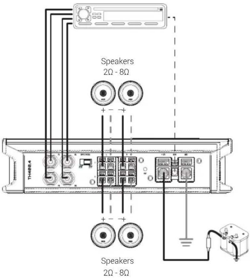
Bridged
Installation

WIRING
TH1400.5
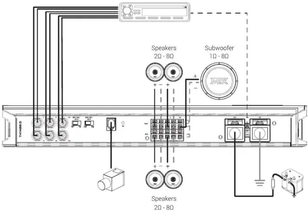

WIRING
TH900.6
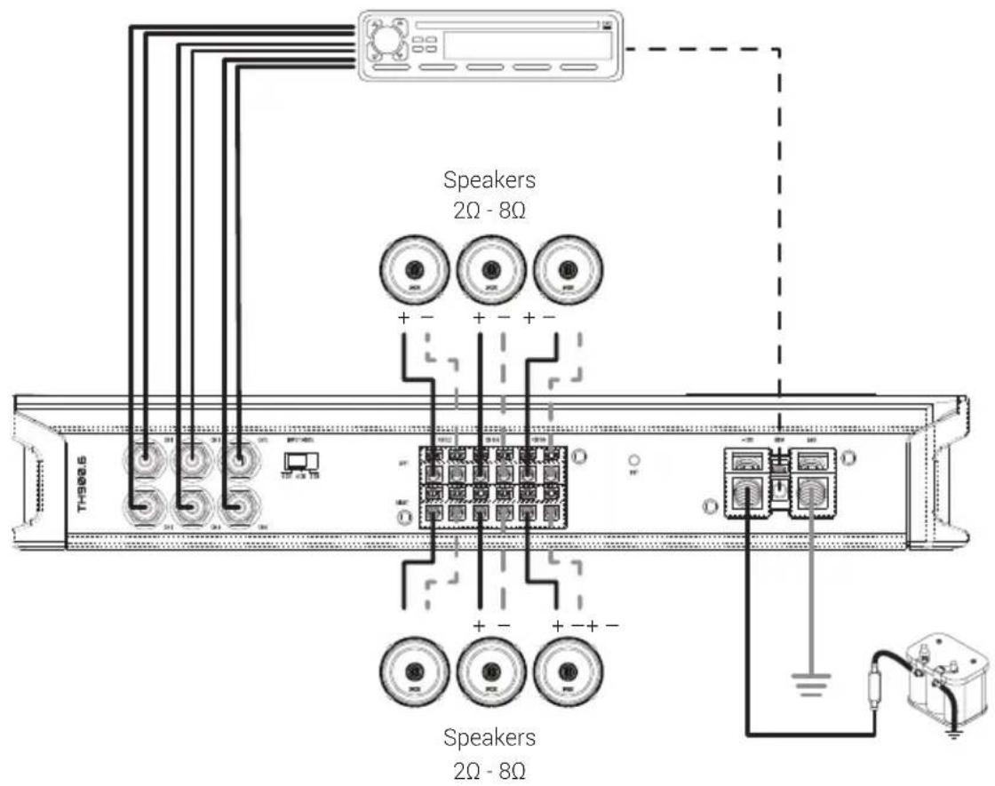

WIRING
TH750.1
TH1500.1
TH2500.1

Subwoofer
1Ω - 8Ω
DIMENSIONS
| Model | Height(A) | Width(B) | Depth(C) |
| TH750.1 | 2"(50mm) | 9^3/_4 "(247mm) | 7"(176mm) |
| TH1500.1 | 2"(50mm) | 11^3/_4 "(297mm) | 7"(176mm) |
| TH2500.1 | 2"(50mm) | 14^1/_2 "(367mm) | 7"(176mm) |
| TH400.4 | 2"(50mm) | 8^3/_16 "(207mm) | 7"(176mm) |
| TH800.4 | 2"(50mm) | 9^3/_4 "(247mm) | 7"(176mm) |
| TH1400.5 | 2"(50mm) | 14^1/_2 "(367mm) | 7"(176mm) |
| TH900.6 | 2"(50mm) | 12^1/_8 "(307mm) | 7"(176mm) |

Model TH750.1 TH1500.1 TH2500.1
| Circuit Topology | Mono Class-D Mono Class-D Mono Class-D | ||
| RMS Power Output at 1Ω | 750W 1500W 2500W | ||
| RMS Power Output at 2Ω | 500W 1000W 1750W | ||
| RMS Power Output at 4Ω | 250W 500W 1000W | ||
| RMS Power Output at 4Ω Bridged | N/A N/A N/A | ||
| Total Harmonic Distortion | <0.1% <0.2% <0.1% | ||
| Signal to Noise Ratio | 00dB >100dB >100dB | ||
| Input Sensitivity | -200mV 10V - 200mV 10V - 200mV | ||
| Crossover Range | 50Hz - 250Hz | 50Hz - 250Hz | 50Hz - 250Hz |
| Frequency Response | 20Hz - 250Hz | 20Hz - 250Hz | 20Hz - 250Hz |
| Bass Boost | 0dB - 12dB | 0dB - 12dB | 0dB - 12dB |
| Subsonic Filter | 10Hz - 55Hz | 10Hz - 55Hz | 10Hz - 55Hz |
| EBC Remote Knob | Yes | Yes | Yes |
| Recommended External Fuse Rating | 80A - 100A | 150A - 200A | 250A - 300A |
| Recommended Power / Ground Cable | 4 AWG | 4 AWG 1/0 AWG |
TH400.4 TH800.4 TH1400.5 TH900.6
| Full Range Class-D Full | Range Class-D Full Range | Class-D Full Range Class-D | |
| N/A N/A | 800W(sub only) | N/A | |
| 100W x 4CH 200W x 4CH 150W x 4CH + 500W | 150W x 6CH | ||
| 50W x 4CH 100W x 4CH 100W x 4CH + 300W | 75W x 6CH | ||
| 200W x 2CH 400W x 2CH | 300W x 2CH(CH1/2/3/4) | 300W x 3CH | |
| <0.1% <0.2% <0.4% <0.1% | |||
| >98dB >98dB >95dB | |||
| 10V - 200mV 10V - 200mV 10V - 200mV | |||
| 40Hz - 400Hz 40Hz - 400Hz | 40Hz - 400Hz (CH1-4)50Hz - 250Hz (Sub) | 40Hz - 400Hz | |
| 20Hz - 20KHz 20Hz - 20KHz | 20Hz - 20KHz (CH1-4)20Hz - 250Hz (Sub) | 20Hz - 20KHz | |
| N/A N/A 0dB - 12dB (Sub) N/A | |||
| N/A N/A 10Hz - 55Hz (Sub) N/A | |||
| No | No | Yes | No |
| 40A - 60A | 60A - 80A 150A - 200A | 100A - 150A | |
| 8 AWG or 4 AWG | 4 AWG | 1/0 AWG | 4 AWG |
NOTES
MITEK WARRANTY
MiTek Mobile products (including, but not limited to: MTX, Coustic, Streetwires, Xtant, BassSlammer, and Thunder Marine) purchased in the USA from an AUTHORIZED MITEK DEALER are guaranteed against defects in material and workmanship for two years. The warranty period begins the day the product is purchased by the end user, and this warranty is limited to the original retail purchaser of product. Products found to be defective during the warranty period will be repaired or replaced with equivalent product by MiTek at no charge. This warranty is void if it is determined that unauthorized parties have attempted repairs or alterations of any nature, and the warranty does not extend to cosmetics or finish. MiTek disclaims any liability for other incurred or consequential damages resulting from product defects. MiTek's total liability will not exceed the purchase price of the product.
We're here to help! If you experience an issue with any of our products, please contact our customer service technical line at 1-800-CALL-MTX to help troubleshoot your issue. If after speaking with our technical experts it is determined that your product is defective, the technician will provide you with a Return Authorization number and all relevant details you'll need to process your claim quickly.
Let's Get Social mtx.com

natural_image
Four black square icons representing social media platforms: Instagram, X, Facebook, and YouTube (no text or symbols beyond logos)Like, Follow, & Subscribe
Brand : MTX Audio
Model : Thunder TH2500.1
Category : Receiver