
HYCP5030 - Vibratory plate HYUNDAI - Free user manual and instructions
Find the device manual for free HYCP5030 HYUNDAI in PDF.


| Product Type | Vibratory Plate |
| Model | HYCP5030 |
| Brand | Hyundai |
| Engine Type | 4-Stroke Petrol |
| Engine Power | 3.5 kW (4.7 HP) |
| Centrifugal Force | 12 kN |
| Vibration Frequency | 90 Hz |
| Plate Size (Length x Width) | 500 x 400 mm |
| Compaction Depth | 20 cm |
| Travel Speed | 20 m/min |
| Fuel Tank Capacity | 3.2 L |
| Oil Capacity | 0.6 L |
| Weight | 30 kg |
| Dimensions (L x W x H) | 800 x 400 x 500 mm |
| Noise Level | 95 dB(A) |
| Vibration Isolation | Rubber mounts on handle |
| Transport Wheels | Included (2 wheels) |
| Maintenance Interval | Every 20 hours of operation |
| Safety Features | Engine cut-off switch, throttle lock |
Frequently Asked Questions - HYCP5030 HYUNDAI
User questions about HYCP5030 HYUNDAI
0 question about this device. Answer the ones you know or ask your own.
Ask a new question about this device
Download the instructions for your Vibratory plate in PDF format for free! Find your manual HYCP5030 - HYUNDAI and take your electronic device back in hand. On this page are published all the documents necessary for the use of your device. HYCP5030 by HYUNDAI.
USER MANUAL HYCP5030 HYUNDAI
COMPACTOR PLATE HYCP5030, HYCP6570, HYCP9070
Instruction Manual

GENUINE PRODUCT OF HYUNDAI CORPORATION

natural_image
Line drawing of a lawn mower with attached equipment (no text or symbols)
CE UK CA
WARNING: Read the instructions carefully before use.
Iss:Oct/24
| CONTENTS | PAGE NO.s | |
| 1 | SAFETY | 3 – 8 |
| 2 | PART LOCATIONS | 9 |
| 3 | ASSEMBLY | 10 – 13 |
| 4 | PRE-OPERATION CHECKS | 12 |
| 5 | STARTING PROCEDURE | 13 – 14 |
| 6 | STOPPING PROCEDURE | 14 |
| 7 | OPERATING INSTRUCTIONS | 15 – 16 |
| 8 | MAINTENANCE | 16 – 23 |
| 9 | TRANSPORTATION & STORAGE | 24 |
| 10 | TROUBLESHOOTING | 25 |
| 11 | SPECIFICATION | 26 |
| 12 | DECLARATION OF CONFORMITY | 27 |
| 13 | RECYCLING & PRODUCT DISPOSAL | 28 |
| 14 | CONTACT DETAILS | 29 |
| 15 | WARRANTY | 29 |
| 16 | MANUAL UPDATES | 29 |
1. SAFETY
1.1 General Safety Notes.
1.2 The operator of the machine is responsible for, and has a duty of care in making sure that the machine is operated safely and in accordance with the instructions in this user manual. Keep the manual safe and pass it on if the machine is loaned or sold to another user.
1.3 Please note the following safety points.
1.4 The machine should never be left it in a condition which would allow an untrained or unauthorised person/s to operate this machine.
1.5 All due care and diligence should be taken by the operator for the safety of and with regard to those around whilst using the machine.
1.6 Some or all of the following - warning signs, symbols and/or PPE pictograms may appear throughout this manual. You MUST adhere to their warnings. Failure to do so may result in personal injury to yourself or those around you.

DANGER
Indicates a hazard, which, if not avoided, could result in serious injury or death.

WARNING
Indicates a hazard, which, if not avoided, could result in serious injury.

CAUTION
Indicates a hazard which, if not avoided, might result in minor or moderate injury.

NOTE
Indicates a situation that could easily result in equipment damage.
READ and keep the manual safe and pass it on if the machine is loaned or sold to another user.
You MUST fully understand all instructions to ensure you use and operate the machine safely.
Appropriate Personal Protective Equipment (PPE), MUST be worn at all times when operating or repairing the machine.






1.10 Carbon Monoxide (where applicable).

1.11 Carbon monoxide is a colourless and odourless gas. Inhaling this gas can cause death as well as serious long term health problems such as brain damage.
1.12 The symptoms of carbon monoxide poisoning can include but are not limited to the following;
Headaches, dizziness, nausea, breathlessness, collapsing or loss of consciousness.
1.13 Carbon monoxide poisoning symptoms are similar to flue, food poisoning, viral infections and simply tiredness. It is quite common for people to mistake this very dangerous poisoning for something else.
1.14 To avoid carbon monoxide poisoning DO NOT use Petrol/Diesel powered equipment inside any of the following; Home, garage, tent, camper van, mobile home, caravan or boat. This is not exhaustive and if you are in any doubt contact your dealer.
1.15 If you think you have or someone around you has been affected by carbon monoxide poisoning;
1.16 Get them fresh air immediately, by leaving the affected area or by opening doors and windows. If safe and practical to do so make sure that the machine is turned off. DO NOT enter a room you suspect of having carbon monoxide present – instead call the emergency services.
1.17 Contact a Doctor immediately or go to Hospital – let them know that you suspect carbon monoxide poisoning.
1.18 DO NOT use in an enclosed area or moving vehicle.
1.20 General Fuel Safety (where applicable).

CAUTION
ALL FUELS ARE FLAMABLE
1.21 Fire Hazard – keep fuel away from all sources of ignition for example heaters.
Lamps, sparks from grinding or welding.
1.22 DO NOT carry out hot work on tanks that have contained fuel.
1.23 ALWAYS keep the work area tidy.
1.24 ALWAYS clean up spills promptly using absorbent granules and a lidded bin.
1.25 ALWAYS dispose of waste fuels correctly.
1.30 Fueling/De-fueling (where applicable).

CAUTION
ALL FUELS ARE FLAMABLE
1.31 ALWAYS fuel and defuel in a well ventilated area outside of buildings.
1.32 ALWAYS wear correct, suitable and fit for purpose Personal Protective Equipment (PPE), suggested items are but not limited to safety gloves, overalls.

1.33 When fueling/de-fueling ALWAYS avoid inhaling fumes.
1.34 When de-fueling ALWAYS use a proper fuel retriever.
1.35 ALWAYS carry fuel in the correct and clearly marked container.
1.40 Electrical Safety (where applicable).
1.41 Electricity can kill – NEVER work on LIVE/ENERGISED equipment.
1.42 Prior to carrying out any maintenance work you MUST identify electrical isolation methods and isolate all electrical supplies.
1.43 Prior to use and with all electrical supplies isolated, you MUST check all electrical cables, plugs and connectors for the following;
1.44 Are intact and have no signs of damage, to include but not limited to bare wires, chaffing, cuts and loose wiring.
1.45 If there are any signs of damage, the damaged item MUST be taken out of service until the damage has been repaired by an electrically competent person.

risk of electric shock
All trailing cables should be routed so as not to cause any kind of trip hazard.
NEVER work on or near electricity with wet hands, wet clothing and wet gloves.
Vibrations (where applicable).
Prolonged use of hand held (operated) machines will cause the user to feel the effects of/from vibrations. These vibrations can lead to white finger (Raynaud's phenomenon) or carpal tunnel syndrome. This condition reduces the ability of the hand to feel and regulate temperature, causing numbness and heat sensations and may cause never damage and circulatory tissue death.
Not all factors that lead to white finger disease are known, but cold weather, smoking and other diseases that affect blood vessels and blood circulation as well as large and long-lasting impact of shocks are considered factors in the formation of white finger. Note the following to reduce the risk of white finger and carpal tunnel syndrome;
Wear gloves and keep your hands warm.
Take regular breaks.
All of the above precautions may help reduce the risk of white finger disease but not rule out the carpal tunnel syndrome. Long-term and regular users are therefore
recommended to observe the condition of your hands and fingers. Seek medical attention immediately if any of the above symptoms should occur.
1.70 Noise (where applicable).
1.71 The operating noise of the machine can damage your hearing. Wear hearing protection such as earplugs or ear defenders to protect your hearing. Long-term and regular users are advised to have hearing checked regularly. Be especially vigilant and cautious when hearing ear protection because your ability to hear alarm warnings will be reduced.
1.72 Noise emissions for this equipment is unavoidable. Carry out noisy work at approved times and for certain periods. Limit the working time to a minimum. For your personal protection and protection of people working nearby it is also advisable for them to wear hearing protection.
1.73 See Certificate of Conformity section for Outdoor Noise declaration of conformity.

MACHINE SPECIFIC SAFETY
1.80 General Machine Safety.
1.81 Read the owner's manual carefully to understand how to operate this machine properly.
1.82 You should NEVER use the machine when;
1.83 Wearing loose clothing, barefoot or sandals.
1.84 Under the influence of drink or drugs or as a result of having taken medication for cold or flu, or any other times when a possibility exists that your judgement might be impaired or that you might not be able to operate the machine properly and in a safe manner.
1.85 Suffering from exhaustion or lack of sleep.
1.86 When the ground is slippery or when other conditions exist which might make it not possible to maintain a steady posture.
1.87 At night, at times of heavy fog, or at any other times when your field of vision might be limited and it would be difficult to gain a clear view of the area.
1.88 During rain storms, lighting storms, at times of strong or gale force winds, or at any other times when the weather conditions might make it unsafe to use this product.
1.89 NEVER run the engine indoors. The exhaust gasses contain harmful carbon monoxide.
1.90 When using this machine for the first time and before actual work, you MUST learn how to handle the machine from an experienced or skilled person.
1.91 Limit the amount of time using the machine continuously to somewhere around 10 minutes per session and take 10 to 20 minutes of rest between sessions. Also try to keep the total amount of work in a single day limited to 2 hours or less.
1.92 NEVER allow children or anyone unable to fully understand the directions given in this manual to operate this product.
1.93 Make sure you keep this manual handy so you may refer to it whenever questions arise and ensure you pass this manual on if the machine is loaned or sold.
1.94 Correct Personal Protective Equipment (PPE) MUST be worn at all times when operating or repairing this machine. This should include but is not limited to;



2. PART LOCATIONS
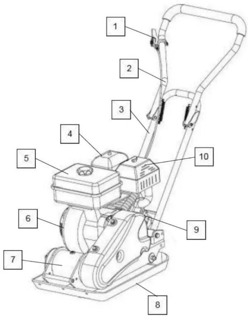
| 1 | Throttle Control | 6 | Engine |
| 2 | Upper Handle | 7 | Exciter |
| 3 | Lower Handle | 8 | Base Plate |
| 4 | Air Filter | 9 | Oil Drain Port |
| 5 | Fuel Tank | 10 | Exhaust |
3. ASSEMBLY

CAUTION
Due to the weight of this machine, it is advisable to seek assistance with assembly.
Check all parts are present before beginning assembly.
HANDLE
3.1 Unfold the upper handle.

3.2 Mount the lower handle to the mounting points on either side of the compactor plate deck.
3.3 Mount the throttle control lever to the mounting point on the upper handle.

WHEEL KIT
3.4 Align the holes in the wheel kit with the mounting points on either side of the compactor plate deck and secure in place.
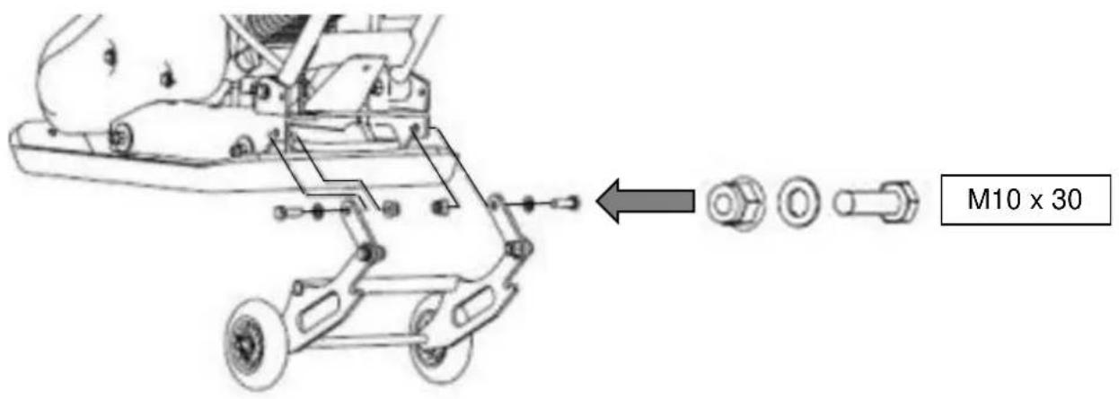
3.5 Before using the compactor plate, you MUST fold up the wheel kit.

natural_image
Line drawing of a lawn mower with visible blades and wheels, no text or symbols present3.6 Attach the paving pad (if required) by aligning the holes on the base plate with the holes in the paving pad and mounting plate.

4. PRE OPERATION CHECKS

NOTE
This machine is shipped without fuel and oil in the engine.
It is essential that fuel and oil levels are checked and maintained before each operation.
ALWAYS check the fuel and oil level with the machine on flat level ground.
| Fuel Type | Unleaded Petrol |
| Engine Oil Type | SAE30 or SAE15W40 Engine Oil |

CAUTION
FOR OUTDOOR USE ONLY
This machine produces carbon monoxide – a poisonous, colourless and odourless gas that can cause death or serious injury.

CAUTION
ALL FUELS ARE FLAMMABLE
ALWAYS handle with extreme care and in a well-ventilated area.
Allow the engine to cool and remove the spark plug HT lead cap before refuelling or defueling.
FUEL
4.0 Place the machine on flat level ground in a well-ventilated area away from any sources of ignition and at least 1.5m away from any buildings.
4.1 Clean the area around the fuel filler cap to prevent dirt and debris from entering the fuel system.
4.2 Unscrew the fuel filler cap and slowly fill with unleaded petrol.
You MUST allow a 25mm gap between the top of the fuel and the top of the fuel tank to allow for fuel expansion.
4.3 Refit the fuel filler cap securely and wipe up any spills.
Upper Limit Mark

natural_image
Pure diagram of two vertical structures with a central vertical line and horizontal base, no text or symbols present.ENGINE OIL
4.4 Place the machine on a flat level surface.
4.5 Clean the area around the oil filler cap/dipstick to prevent dirt and debris from entering the engine.
4.6 Unscrew and remove the oil filler cap/dipstick.
4.7 For machines without a dipstick, the oil level is determined by filing to the upper thread level.
For machines with a dipstick, the oil level is determined by the upper level limit make on the dipstick.
4.8 Slowly fill with oil to the correct level. Stop occasionally and check the level.
DO NOT overfill.
4.9 Once full, refit the oil filler cap/dipstick and tighten securely.

natural_image
Illustration of a cartoon fish jumping from a container into a tank (no text or symbols)5. STARTING PROCEDURE

NOTE
This machine is shipped WITHOUT fuel and oil and will require filling BEFORE use. Failure to do so will result in engine damage that will not be covered by the warranty.

CAUTION
Before starting, ensure the machine is clear of materials and all non-essential persons.
5.0 Move the fuel tap to the 'ON' position and turn the ignition switch to the 'ON' position.

5.1 COLD START: Move the choke lever to the 'START' position. WARM START: Leave the choke lever in the 'RUN' position.

flowchart
graph TD
    A["START"] --> B["CHOKE LEVER"]
    B --> C["RUN"]
5.2 Gently pull the recoil start handle until you feel resistance, the pull swiftly.
5.3 Repeat until the engine starts.
DO NOT let go of the recoil handle, instead return the handle to the start position slowly.
5.4 Once the engine has started, move the choke lever between the START/RUN positions and adjust until the engine runs smoothly.
5.5 Once the engine has warmed up, move the throttle lever on the handlebars to the desired working speed.
6. STOPPING PROCEDURE
6.0 Move the throttle lever to the SLOW position.
6.1 Allow the engine to sit at idle under no load for 20 seconds.
6.2 Turn the engine switch to the 'OFF' position.
6.3 Turn the fuel tap to the 'OFF' position.
EMERGENCY STOP
6.4 In an emergency, move the engine switch to the 'OFF' position.
NOTE: Only use in case of emergency as continual use of the emergency stop procedure could cause damage to the machine.
7. OPERATING INSTRUCTIONS

NOTE
This machine is shipped WITHOUT Oil and Fuel and will require filling BEFORE use.
Failure to do so will result in engine damage that will not be covered by the warranty.

WARNING
You MUST STOP the machine if any of the following occur;
The engine speed changes with no control.
In case of misfire or unusual noise.
In case of high vibration.
In rain or stormy weather.

CAUTION
FOR OUTDOOR USE ONLY
This machine produces carbon monoxide – a poisonous, colourless and odourless gas that can cause death or serious injury.
Petrol is highly flammable, always handle with extreme care and in a well-ventilated area.
ALWAYS remove the HT lead from the spark plug when checking the machine, refuelling or changing parts.

CAUTION
If you are not familiar with this type of machine, you should seek advice and guidance from your dealer.
DO NOT attempt to lift the machine with the engine running.
7.0 After the engine warms up, pull the throttle lever to accelerate the engine speed.
7.1 The plate will begin vibrating and begin to move forward.
7.2 The plate compactor is designed to run at an engine speed (engine take off shaft) of 3600rpm (normally considered full throttle).
7.3 Running the engines at lower rpm's will result in a decrease in compaction force and a lower travel speed.
It will create excessive ‘out-of-sync’ vibrations resulting in poor compaction, manoeuvrability, excessive wear to the machine and discomfort for the operator.
7.4 In operation, guide the machine but let the compactor do the work.
7.5 Bearing down on the handle is unnecessary and will cause shock absorber wear.
7.6 On level surfaces the compactor moves forwards rapidly.
7.7 On uneven surfaces or inclines, light forward pressure on the handle may be required to assist the compactor in moving forward.
7.8 The number of passes required to reach a desired compaction level will depend on the type and moisture content of the soil.
7.9 Maximum compaction has been reached when excessive kickback is noticed.
7.10 NOTE
When using a compactor on asphalt, a water sprinkler kit (not included) is required to help prevent the bottom plate from adhering to the hot asphalt surface.
7.11 NOTE
When using on paving stones or similar, attach a paving pad to the bottom of the plate to prevent the compactor from marking or chipping the surface of the stones.
7.12 While a certain amount of moisture in the soil is necessary, excessive moisture can cause soil particles to stick together and prevent good compaction. If the soil is extremely wet, allow to dry before compacting.
7.13 If the soil is as dry to cause dust clouds while operating the plate, some moisture should be added to the ground material to improve compacting. This will also reduce air filter servicing.
8. MAINTENANCE
!
WARNING
ALWAYS stop the engine, allow it cool and remove the spark plug HT lead cap before doing any maintenance or repairs.
Check and maintain the oil and fuel levels regularly.
At regular intervals check the tightness or all nuts, bolts and screws.
If the machine hits an obstacle, stop and check for damage.
Any damage must be repaired before continuing to use the machine.
!
CAUTION
ALWAYS fuel and defuel in a well-ventilated area with the engine off and allowed to cool.
Whilst carrying out any maintenance, you MUST wear the appropriate Personal Protective Equipment (PPE).
!
CAUTION
NEVER use a pressure washer or hosepipe to clean the machine.
Water can penetrate areas of the machine and cause damage to the spindles, pulleys, bearings and engine.
The use of a pressure washer or hosepipe will shorten the lifespan and reduce serviceability.
!
NOTE
Only use manufacturer recommended parts when servicing or repairing this machine. The use of non-recommended parts may shorten the machines lifespan and void the warranty.
| Each Use | 1^st Month or 20 Hours | Every 50 Hours | Every 6 Months or 100 Hours | Every Year or 300 Hours | ||
| Engine Oil | Check | ● | ||||
| Replace | ● | ● | ||||
| Air Filter | Check | ● | ||||
| Replace | ● | |||||
| Spark Plug | Check | ● | ||||
| Replace | ● | |||||
| Fuel Filter | Clean | |||||
| Replace | ● | |||||
| Spark Arrestor | Clean | ● | ||||
| Belt Tension | Check | ● | ● | |||
| Fuel Lines | Check | ● | ||||
| Fuel Tank | Check | ● | ||||
| Idle Speed | Check | #● | ||||
| Adjust | #● | |||||
| Valve Clearance | Check | #● | ||||
| Adjust | #● | |||||
We recommend these service items are carried out by an authorised service dealer.

CAUTION
Risk of Burn from hot oil.
Allow the oil to cool to WARM before changing.
Warm engine oil will drain effectively.
| Oil Type | SAE30 or SAE15W40 Engine Oil |
Drain the engine oil while the engine is warm. Warm oil will drain more effectively.
Clean the area around the oil filler/dipstick and do not allow any dirt or debris to enter the engine.
Remove the oil filler/dipstick and place a suitable container underneath the oil drain plug.
Unscrew the oil drain plug and allow the oil to drain. Your machine may have a flexi-pipe connected to the oil drain, unscrew the end shown below and drain.
Once the oil has drained, check the drain plug for damage.
If damaged, replace immediately.
Reinstall the drain plug by hand to avoid cross threading, once seated tighten securely.
With the machine on flat level ground, slowly fill with fresh engine oil.
Stop occasionally to check the level.
For machines fitted with a dipstick, fill to the upper level mark on the dipstick.
For machines without a dipstick, fill to the upper thread level on the oil fill hole.
Refit the oil filler cap/dipstick securely.
Wipe up any spilt oil.

AIR FILTER

NOTE
NEVER run the machine without an air filter being installed.
A dirty air filter element affects the engine performance, increases fuel consumption and will make it difficult to start.
If you notice a loss of power, check the air filter.
You must ensure that the air filter housing is free of dust and debris. DO NOT allow any dirt or debris to enter the carburettor.
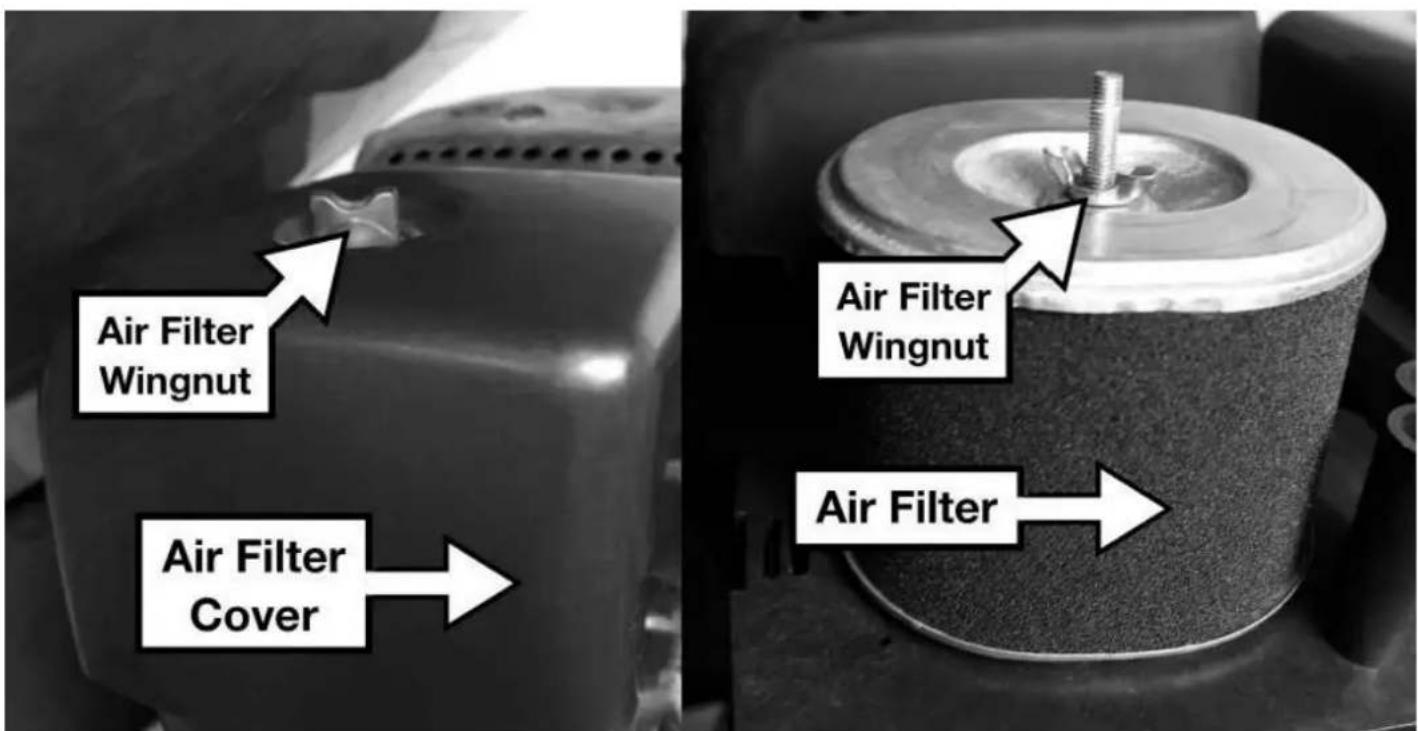
8.10 Remove the air filter cover by unscrewing the air filter cover wing nut and remove the cover.
8.11 Undo the air filter element wing nut and remove the air filter element.
8.12 Ensure that no dirt or debris can enter the carburettor.
8.13 Remove the foam filter element (if installed) from the paper element.
8.14 Inspect the air filter and if it shows any signs of damage or wear, replace immediately.
8.15 Tap the paper element to remove dirt and debris and use a low pressure air-line to blow from the inside of the element to remove the remaining dust.
8.16 If installed, was the foam element in a warm soap solution and allow to air dry.
DO NOT twist the element to dry.
8.17 Once dry, soak the foam element in fresh engine oil and remove any excess.
8.18 Reinstall the foam element over the paper element and reinstall back on to the machine.
SPARK PLUG

CAUTION
ALWAYS allow the engine to cool completely before removing the spark plug.

NOTE
ALWAYS replace the spark plug with the same model.
Incorrect spark plug installation can cause serious engine damage.
DO NOT allow dirt or debris to enter the cylinder bore.
8.19 Remove the spark plug HT lead cap.
8.20 Using a plug wrench, unscrew the spark plug in an anti-clockwise direction.
8.21 Inspect the spark plug and spark plug washer for any signs of wear or damage.
If the plug show any signs of wear or damage, the replace immediately.
8.22 Remove any carbon deposits from the spark plug electrode by using a soft wire brush.
8.23 The spark plug gap should be 0.70 - 0.80 mm (0.028" - 0.031").
Check the plug gap by using a feeler gauge. The gauge must drag a little when being slid between the electrodes.

8.24 Refit the spark plug by hand to avoid cross threading.
8.25 Once the spark plug seats, tighten the spark plug to a torque of 12 to 15Nm.
TENSIONING BELTS
Tensioning the Belt(s)
NOTE: The normal belt deflection on each side should be 9 to 13mm. This should be checked after the first 20 hours use then every 50 hours thereafter.
8.26 Proper belt tensioning is critical to good performance and will ensure long belt life.
Too much or too little belt tension will cause premature belt failure.
8.27 Undo and remove the belt guard.
8.28 Loosen the four engine mount bolts (do not remove) only enough to move the engine forward.
8.29 Loosen the jam nuts (B) leaving enough space between the nut and bracket.
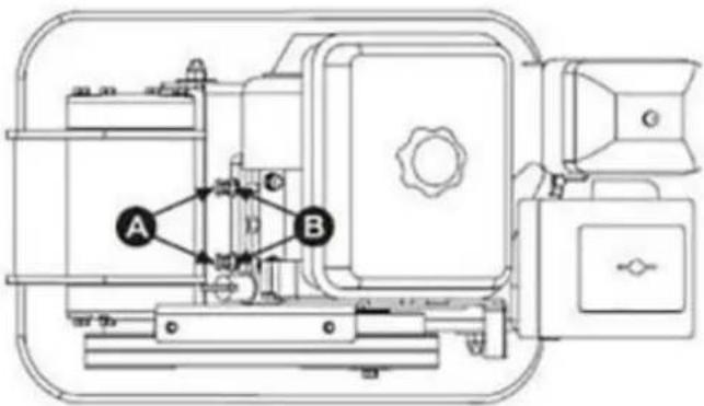
8.30 Push the engine toward the back of the plate by turning the adjustment bolts A to remove any slack in the V-belt(s).
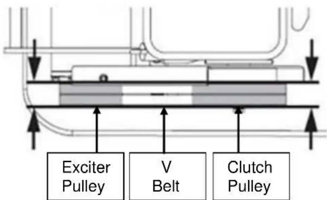
8.31 When adjusting the belt(s), make sure that the clutch pulley is in alignment with the exciter pulley.
8.32 When the V-belt tension is correct, tighten the jam nuts B against the bracket.
8.33 Tighten the engine mount bolts.
8.34 Replace the belt guard.
8.35 NOTE: If the adjustment bolts have no more adjustment left, the belt(s) may have to be replace.
Replacing the V Belt(s)

NOTE
For models HYCP6570 & HYCP9070 both V belts should be replaced at the same time because they will wear evenly through normal use. Work on one belt at a time.
8.36 Undo and remove the belt guard.
8.37 Loosen the 4 engine mount bolts (do not remove) only enough to move the engine forward.
8.38 Loosen the jam nuts B and bolts A.
8.39 Slide the engine toward the front plate and slip the V Belt(s) off the pulley.
8.40 Install the new belt.
8.41 Position the V belt(s) over the engine pulley.
8.42 Move the engine back.
8.43 NOTE: When adjusting the belt(s), make sure that the clutch pulley is in alignment with the exciter pulley.
8.44 When the V-Belt tension is correct, tighten the Jam nuts B and the engine mount bolts.
8.45 Replace the belt guard.
EXCITER LUBRICATION
Agitator is pre-filled with oil. Change oil every 200 hours use.
| HYCP5030 HYCP6570 HYCP9070 | |||
| Exciter Oil Capacity – ml | 80 80 100 | ||
| Exciter Oil Type | SAE30 or 15W40 | ||
8.46 Allow the exciter to cool before changing the oil.
8.47 Remove the belt guard and V-belt(s).
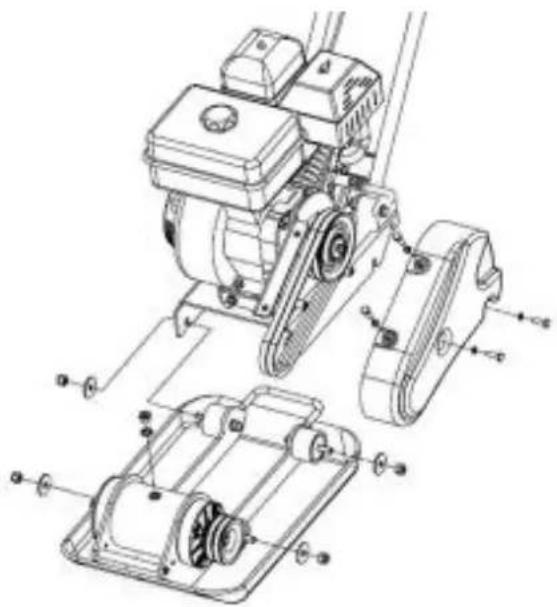
8.48 Remove the bolts that hold the deck to the housing and lift the entire deck, with engine, away from the housing.
natural_image
Technical line drawing of a mechanical assembly with exploded view and component labels (no readable text or symbols)8.49 Remove the pipe plug for the top of the exciter housing.
8.50 Place a suitable container underneath the machine.
8.51 With assistance, tilt the housing upside down to allow the oil to drain.

natural_image
Diagram of a mechanical device with a downward arrow indicating flow or movement, and a small bowl below (no text or symbols)8.52 Examine the oil to check for metal chips as a precaution.
8.53 Return the housing to an upright position.
8.54 Refill the exciter with the correct amount of oil.
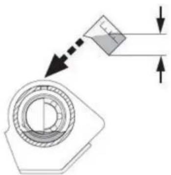
DO NOT overfill as overfilling can cause the excess oil to leak out of the breather. The breather is a hole drilled through the output shaft of the agitator.
natural_image
Technical diagram showing a mechanical component with directional arrows and dimension lines (no text or symbols)8.55 Once the oil is at the correct level, apply pipe sealant to the pipe plug and reinstall into the top of the exciter housing.
8.56 Reinstall the deck, V-belt(s) and belt guard.
CLEANING
8.57 DO NOT use a pressure washer or hose pipe to clean the machine.
Water could penetrate the engine and cause failure.
8.58 Use a brush to remove large pieces of debris then wipe over with a moist cloth.
8.59 Use a silicone based grease to lubricate moving parts.
8.60 DO NOT use any solvent based cleaning products to clean the machine. This could damage plastic components.
9. TRANSPORTATION & STORAGE

CAUTION
ALWAYS all the machine to cool completely before storage or transportation.
TRANSPORT
9.0 Drain the fuel tank using a siphon or similar fuel retrieval device.
9.1 Store the fuel in a suitable fuel container for transport.
9.2 Allow the engine to cool completely.
9.3 Ensure the fuel tap and engine switch are in the off position.
9.4 Secure the machine upright in the vehicle so it cannot move during transportation.
9.5 Fuel and its vapours are flammable so keep away from possible sources of ignition.
STORAGE

NOTE
If the machine is to be stored for periods of 30 days or more, then it is essential to prepare the machine for storage correctly.
Failure to do so could result in issues making the machine difficult to start or cause poor running.
9.6 Drain the fuel tank using a siphon or similar fuel retrieval device, into a suitable fuel container.
9.7 Run the engine under no load until the machine stops, to remove any remaining fuel from the carburetor and fuel lines.
9.8 Allow the engine to cool completely.
9.9 Drain the engine oil from the engine following the procedure laid out in the maintenance section of this manual and refill with fresh engine oil.
9.10 Clean the area around the spark plug and remove the spark plug following the procedure laid out in the maintenance section of this manual.
9.11 Pour a teaspoon of fresh engine oil down the spark plug hole into the cylinder bore.
9.12 Gently pull the recoil start handle 4 to 5 times to coat the cylinder wall with a coating of fresh engine oil.
9.13 Refit the spark plug but leave the spark plug HT lead cap removed.
9.14 Clean the machine following the cleaning procedure as laid out in the maintenance section of this manual.
9.15 Check the tightness of all nuts, bolts and screws.
9.16 Store upright, in a call dry place away from extremes of temperature change and away from any possible sources of ignition
10. TROUBLESHOOTING
| Problem | Possible Cause | Possible Solution |
| Engine fails to start | Spark plug HT lead cap disconnected | Re-attach spark plug HT lead cap |
| Out of fuel or stale fuel | Fill with clean fresh fuel | |
| Throttle control lever not in correct starting position | Move throttle control lever to start position | |
| Choke not in the ON position | Move choke to the ON position | |
| Blocked fuel line | Clean fuel line | |
| Fouled spark plug | Clean, adjust gap | |
| Engine flooding | Wait a few minutes before starting, do not re-prime | |
| Engine runs erratically | Spark plug wire loose | Connect and tighten spark plug wire |
| Machine running on choke | Move choke lever to off position | |
| Blocked fuel line or stale fuel | Clean fuel line and refill with fresh fuel | |
| Fuel filler cap vent plugged | Clear vent | |
| Water or dirt in fuel system | Drain and clean fuel tank, refill with fresh fuel | |
| Dirty air filter | Clean or replace air filter | |
| Engine overheats | Engine oil level low | Fill oil to correct level |
| Dirty air filter | Clean or replace air filter | |
| Airflow restricted | Remove blower housing and clean | |
| Engine will not stop when throttle is positioned at stop | Debris interfering with throttle linkage | Clean and remove debris |
| Compactor is difficult to control when in operation | Engine speed to high | Set the throttle lever at lower speed |
11. SPECIFICATION
| HYCP5030 | HYCP6570 | HYCP9070 | |
| Engine Size - cc | 78.5 196 | 196 | |
| Engine Type | Hyundai 4 Stroke Single Cylinder OHV | ||
| Fuel Type | Unleaded Petrol | ||
| Oil Type | SAE 30 or SAE15W40 Engine Oil | ||
| Plate Size (LxW) - mm | 490 x 320 | 510 x 370 | 540 x 420 |
| Centrifugal Force - N | 8200 | 11000 | 13000 |
| Exciter Speed (VPM) | 5900 | 5500 | 5500 |
| Compaction Depth - mm | 150 | 250 | 300 |
| Exciter Oil Type | SAE30 or 15W40 | ||
| Exciter Oil Capacity | 80ml 80ml 100ml | ||
| Weight - Kg | 46.5 58 78 | ||
12. DECLARATION OF CONFORMITY
12.0 Genpower confirms that this Hyundai product conforms to the following CE Directives;
2006/42/EC Machinery Directive
2004/108/EC EMC Directive
2000/14/EC Amended by 2005/88/EC Noise Emissions Directive
97/68/EC 2010/26/EC NRMM Emissions Directive
EC DECLARATION OF CONFORMITY
The undersigned. As authorised by: Genpower Ltd Declares that the following equipment manufactured under licence by Hyundai Holdings, Korea
Conforms to the Directive:
2000/14/EC (as amended)
Of the European Parliament and of the council on the approximation of the laws of the Member States relating to the noise emission in the environment by equipment for the use outdoors.
Equipment Category: Compaction Machinery
Product Name/Model: HYCP5030
HYCP6570
HYCP9070
Type/Serial No:
Petrol Driven Compactor Plate
Net installed power:
HYCP5030: 78.5
HYCP6570:196cc
HYCP9070: 196cc
The technical documentation is kept by:
Roland Llewellin, Genpower Ltd
Isaac Way, Pembroke Dock,
Pembrokeshire, SA72 4RW.
The conformity assessment procedure followed was in accordance with annex V of the Directive.
Notified Body: TÜV SUD Product Service GmbH
Measured Sound Power Level:
HYCP5030 : 91dB
HYCP6570 : 91dB
HYCP9070:91dB
Guaranteed Sound Power Level:
HYCP5030 : 104dB
HYCP6570 : 106dB
HYCP9070 : 108dB
A copy of this certificate has been submitted to the European Commission and the EU Member State United Kingdom.
Place of Declaration: Pembroke Dock, SA73 4RW
Date: 26/01/2016
Signed by: Roland Llewellin
RJLevelm
Position in Company: Managing Director
Name and address of manufacturer or Authorised representative:
Genpower Ltd
Isaac Way, Pembroke Dock,
Pembrokeshire, SA72 4RW
13. RECYCLING & PRODUCT DISPOSAL
13.0 We do not offer a take back scheme for the recovery of Waste Electrical Electronic Equipment (WEEE) & Batteries.
Instead the responsibility to dispose of WEEE and or batteries is passed on to you by us.
So when it becomes necessary to dispose of your machine you must take it to your Local Civic Amenity Site.
For further information, please contact your Local Authority for disposal advice.
13.1 You MUST make sure that all unused oil and fuel is disposed of correctly either beforehand or at your Local Amenity Site.
Under NO circumstances must any fuel or oil be put down any drains.
13.2 Certain products contain WEEE waste which should not be disposed of in your domestic waste.
13.3 You MUST recycle WEEE in accordance with your Local Authority or Recycling Centre.
13.4 Certain products contain batteries which should not be disposed of in your domestic waste.
13.5 You MUST recycle batteries in accordance with your Local Authority or Recycling Centre.
13.6 Unwanted packaging and materials should be stored and taken to a recycling centre so it can be disposed of in a manner which is compatible with the environment.
13.7 The following symbol means you should 'Reduce – Reuse - Recycle'.

natural_image
Simple line drawing of a trash bin with two crossed lines indicating no waste or prohibition (no text or symbols)
13.8 We are a member of VALPAK National Compliance Scheme and out registration number is RM08660.
13.9 For further information about disposal, please contact your Local Authority.
13.10 You can also get more advice and guidance about recycling at the following website http://www.recycle-more.co.uk
13.11 Should you pass this product on to another user either sold or loaned, you MUST pass on this user manual. This will make sure that all other users can use and maintain this machine safely.
14. CONTACT DETAILS
14.0 ADDRESS
Genpower Ltd, Isaac Way,
London Road, Pembroke Dock,
Pembrokeshire.
SA72 4RW. UK.
14.1 TELEPHONE
+44 (0) 1646 687880
14.2 SUPPORT
aftersales@hyundaipowerproducts.co.uk
14.3 WEBSITE
www.hyundaipowerproducts.co.uk
15. WARRANTY
15.0
Proof of purchase will be required before you make a warranty claim.
Full warranty terms and conditions can be found on the HYUNDAI POWER
PRODUCTS website:
www.hyundaipowerproducts.co.uk
16. MANUAL UPDATES
16.0 Our manuals are constantly being reviewed and updated.
However if you find an error, omission or something you find unclear, please contact your dealer for assistance.
16.1 Our latest manuals are also placed online.
HYUNDAI
POWER PRODUCTS

GENUINE PRODUCT OF HYUNDAI CORPORATION
For Inquiries, Please Contact:
GENPOWER LTD
Isaac Way, London Road,
Pembroke Dock, UK, SA72 4RW.
T: +44 (0) 1646 687 880
E: info@hyundaipowerproducts.co.uk
www.hyundaipowerproducts.co.uk

- COMPACTOR PLATE HYCP5030, HYCP6570, HYCP9070
- SAFETY
- General Safety Notes.
- DANGER
- WARNING
- CAUTION
- NOTE
- Vibrations (where applicable).
- Noise (where applicable).
- MACHINE SPECIFIC SAFETY
- General Machine Safety.
- PART LOCATIONS
- ASSEMBLY
- HANDLE
- Unfold the upper handle.
- WHEEL KIT
- PRE OPERATION CHECKS
- FOR OUTDOOR USE ONLY
- ALL FUELS ARE FLAMMABLE
- FUEL
- ENGINE OIL
- STARTING PROCEDURE
- STOPPING PROCEDURE
- EMERGENCY STOP
- OPERATING INSTRUCTIONS
- MAINTENANCE
- We recommend these service items are carried out by an authorised service dealer.
- AIR FILTER
- SPARK PLUG
- TENSIONING BELTS
- Tensioning the Belt(s)
- Replacing the V Belt(s)
- EXCITER LUBRICATION
- CLEANING
- TRANSPORTATION & STORAGE
- TRANSPORT
- STORAGE
- TROUBLESHOOTING
- SPECIFICATION
- DECLARATION OF CONFORMITY
- EC DECLARATION OF CONFORMITY
- RECYCLING & PRODUCT DISPOSAL
- CONTACT DETAILS
- WARRANTY
- MANUAL UPDATES
- HYUNDAI
- POWER PRODUCTS
Brand : HYUNDAI
Model : HYCP5030
Category : Vibratory plate