
Workhorse Powerhouse - Rack audio Radial Engineering - Free user manual and instructions
Find the device manual for free Workhorse Powerhouse Radial Engineering in PDF.


| Product Type | Power Supply Module for Workhorse Rack |
| Form Factor | 1U Rackmount (Single Slot Module) |
| Dimensions (H x W x D) | 1.75 x 1.5 x 6 inches (4.4 x 3.8 x 15.2 cm) |
| Weight | 1.1 lbs (0.5 kg) |
| Input Voltage | 100-240 VAC, 50/60 Hz |
| Power Consumption | 60W max |
| Phantom Power Output | +48V DC, 14 channels, 10 mA per channel |
| DC Output | +12V DC, 500 mA |
| Number of Slots Supported | 14 |
| Overcurrent Protection | Yes, per channel (PTC resettable fuse) |
| Short Circuit Protection | Yes, power supply shutdown with auto-recovery |
| LED Indicators | Power On, Phantom Active, Overload |
| Cooling | Passive, convection cooled (no fan) |
| Compatibility | Radial Workhorse chassis (all versions) |
| Mounting | Slides into Workhorse chassis slot |
| Power Cord | Detachable IEC C14 inlet, 6 ft (1.8 m) cable included |
| Safety Certifications | CE, FCC, RoHS |
| Operating Temperature | 0°C to 40°C (32°F to 104°F) |
| Storage Temperature | -20°C to 60°C (-4°F to 140°F) |
| Cleaning | Dry cloth; avoid solvents; unplug before cleaning |
| Repair Service | Contact Radial Engineering authorized service centers |
| Spare Parts | Available through Radial distributors; includes fuses, power cord |
| Warranty | 3 years limited (parts and labor) |
| Included Accessories | Power cable, user manual, quick start guide |
Frequently Asked Questions - Workhorse Powerhouse Radial Engineering
User questions about Workhorse Powerhouse Radial Engineering
0 question about this device. Answer the ones you know or ask your own.
Ask a new question about this device
Download the instructions for your Rack audio in PDF format for free! Find your manual Workhorse Powerhouse - Radial Engineering and take your electronic device back in hand. On this page are published all the documents necessary for the use of your device. Workhorse Powerhouse by Radial Engineering.
USER MANUAL Workhorse Powerhouse Radial Engineering
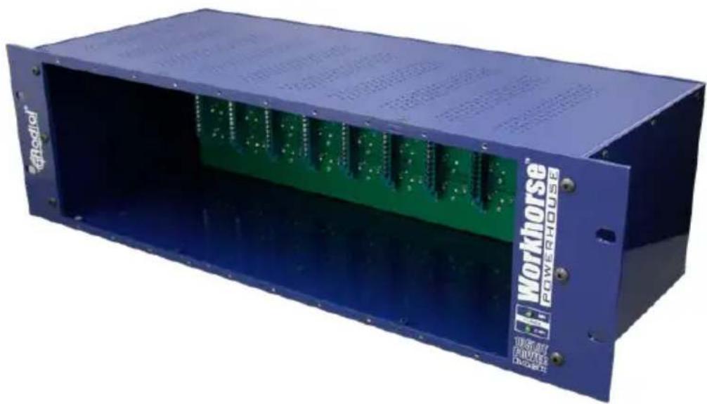
Workhorse™ Powerhouse™
500 Series Rack
natural_image
Blue industrial powertrain box with green circuit board and 'Workhorse POWERHOLD' branding (no readable text beyond label)User Guide

IMPORTANT SAFETY & USER NOTICE - FOR PROFESSIONAL USE
The Radial® Workhorse™ Powerhouse™ is specifically designed for use by qualified professional audio engineers. The open frame design is not intended for use by consumers or those unfamiliar with this format. Even though the current and voltage levels are relatively low, we recommend that all slots be filled with a module or covers be placed over unfilled slots. This will help protect you from electrical shock.
The Powerhouse rack frame is designed to be used with 500 series or what are commonly known as Lunchbox™ modules. The Workhorse Powerhouse has been designed following the framework as outlined by the VPR Alliance as described on the API™ website. Although some manufacturers build modules that are not VPR compliant, they may in fact work with the Powerhouse. Please consult those specific manufacturers for details regarding their compatibility. The Radial Workhorse Open Source Document outlines the required technical specifications for manufacturers that intend to have their modules used in a Workhorse or Powerhouse frame. Compatibility of any modules other than a module made by Radial Engineering Ltd. is the sole responsibility of the user. Please read the Limited Radial Warranty for details. There are no replacement or user serviceable parts inside.

SAFETY NOTICE - NO HOT SWAPPING OF MODULES
Hot Swapping, or exchanging modules while the power is on is not covered under the Radial Limited Warranty. The user is responsible for any damage to the Workhorse Powerhouse or module arising out of hot swapping and the user shall save Radial Engineering Ltd. harmless should any damage occur. Please consult the Radial Limited Warranty for further details.
Radial® Workhorse™ Powerhouse™
500 Series Power Rack
Table of Contents Page
Feature set overview ....1
Introduction & basic functions....3
Omniport....5
Power supply capacity....6
Sliding modules in and out 7
Signal flow and levels 8
Using the Powerhouse 9
Radial Limited Warranty ....Back Cover
Congratulations and thank you for purchasing the Radial Workhorse Powerhouse, an innovative ten module card frame designed for the 500 series modular format. This guide describes how to approach using the Powerhouse, and how to install modules safely. We recommend that you take a few minutes to read it in order to familiarize yourself with the many innovative features that are built in.
To make this guide as easy to understand as possible, we have divided it into several sections. It begins with an overview, then descriptions of each function, ending with some real world applications. Should you have any questions, comments or concerns not covered in these pages, we invite you to log onto the Radial web site at www.radialeng.com and visit the Powerhouse FAQ section. This is where we post the latest updates and answers from users. If you do not find what you need, feel free to send us an email at info@radialeng.com and we will do our best to answer your question as quickly as possible.
Now get ready to bring the fun & excitement of old school analog into your signal path.
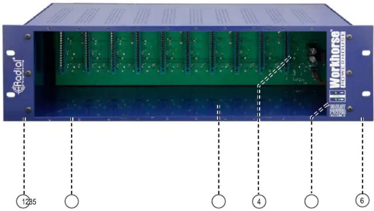
FRONT PANEL FEATURE SET
-
STANDARD 19" RACK: The Powerhouse fits ten 500 series modules into only three spaces. (3RU)
-
10 SLOT RACK: Compatible with new Radial and older 500 series modules to create elaborate signal chains.
-
MIL-SPEC PCB: Double sided, military grade with parts soldered on both sides for durability. Full ground plane to reduce noise.
-
SAFETY CIRCUITS: Protects the rack and adjacent modules from arcing and shorts in case of accidental disconnect.
-
POWER LEDs: Indicators provide visual status for +/-16 volt rail voltage and 48 volt phantom power.
-
SOLID STEEL: 'Road ready' 14 gauge steel construction with welded corners for greater durability and improved shielding.
REAR PANEL FEATURE SET

-
1600 MILLIAMP SUPPLY: Provides plenty of current to be shared between modules. Perfect for high current demand tube devices!
-
GROUND LUGS: Separate chassis and earth ground lugs for studios with sophisticated grounding schemes.
-
STEREO LINK: Linking stereo-ready modules together is done by sliding the LINK switch into the up position.
-
FEED FUNCTION: Sends the output from one module to the input of the next, eliminating the need for patch cables.
-
XLR CONNECTORS: Standard XLR connectors with large channel ID numbers on each slot make it quick & easy to patch with professional balanced line level gear.
-
TRS CONNECTORS: Balanced 14 " I/O are wired in parallel with XLRs. Used to cross-patch modules and for parallel processing.
-
OMNIPORT: 14 " TRS changes function depending on the module installed. Determined by the manufacturer.
INTRODUCTION
The Powerhouse is a card-slot power frame designed for 500 series modules. Up to ten modules may be used at any one time. The Powerhouse routes the modules to the XLR and 1/4 TRS connectors on the rear panel via a 15-pin card-edge receptacle. Radial modules and those that have been designed by other manufacturers to take advantage of the Workhorse's extra features will enjoy the added functionality of the Omniport™.

flowchart
graph TD
    subgraph_CARD_SLOT_1["CARD-SLOT 1"]
        A["INPUT"] --> B["EDAC 15-pin card edge"]
        C["OUTPUT"] --> B
        D["INPUT OUTPUT"] --> B
        E["OUTPUT"] --> B
        F["OUTPUT"] --> B
        G["OUTPUT"] --> B
        H["OUTPUT"] --> B
        I["OUTPUT"] --> B
    end

    subgraph_CARD_SLOT_2["CARD-SLOT 2"]
        J["INPUT"] --> K["EDAC 15-pin card edge"]
        L["OUTPUT"] --> K
        M["INPUT OUTPUT"] --> K
        N["OUTPUT"] --> K
        O["OUTPUT"] --> K
        P["OUTPUT"] --> K
        Q["OUTPUT"] --> K
        R["OUTPUT"] --> K
        S["OUTPUT"] --> K
        T["OUTPUT"] --> K
    end

    B -->|LINK| U["OMNIPORT OMNIPORT"]
    B -->|SWITCH| V["EMNIPORT OMNIPORT"]
    K --> W["EMNIPORT OMNIPORT"]
    style CARD_SLOT_1 fill:#f9f,stroke:#333
    style CARD_SLOT_2 fill:#bbf,stroke:#333
This flow chart shows the basic signal routing. The signal comes into the Powerhouse via the rear panel XLR female or 14 " TRS inputs. Once the signal goes into a module it is processed and sent to the male XLR and parallel 14 " TRS output. From here the signal can be routed to the next adjacent module via the FEED switch connection as described in the next section.
CARD SLOT I/O CONNECTIONS
Each of the Powerhouse card-slots is equipped with XLR and 14 " TRS inputs and outputs. The input sensitivity will be dependant on the type of module being used. For instance, if you are using a microphone preamplifier, the input will of course be suited for a low level microphone. If you are using a dynamic processor like a limiter or an EQ, then the input will usually be set to handle a professional +4dB balanced line-level signal.
Following 500 series convention, the XLR and TRS outputs usually produce a +4dB balanced line-level signal that is able to feed a professional recording system or line-level mixing console.
Put simply, the input level is determined by the type of module being used while the output level will typically be a balanced +4dB line level signal. If you use 14 " mono cables you will unbalance the signal. This will reduce the level by about -6dB but everything will still remain completely functional. Simply adjust the levels to compensate.

FEED SWITCH
As you delve further into the functionality of the 500 series, you will find that the modular format allows all kinds of connectivity options. With older 500 series racks, connections between modules were done using an XLR cable whereby the output from one module would plug into the input of another. The Powerhouse simplifies the process by introducing a FEED switch on the rear panel. This connects the balanced output of one module to the adjacent module to the immediate left when viewing the rear panel.

flowchart
graph TD
    INPUT3["INPUT-3"] --> A["Square Block"]
    INPUT2["INPUT-2"] --> B["Square Block"]
    INPUT1["INPUT-1"] --> C["Square Block"]
    OUTPUT3["OUTPUT-3"] --> A
    OUTPUT3 --> B
    OUTPUT3 --> C
    CARD_SLOT2["CARD-SLOT 2"] --> B
    CARD_SLOT2 --> C
    CARD_SLOT2 --> D["CARD-SLOT 1"]
    D --> E["Square Block"]
    C --> F["Square Block"]
    style INPUT3 fill:#f9f,stroke:#333
    style INPUT2 fill:#f9f,stroke:#333
    style INPUT1 fill:#f9f,stroke:#333
    style OUTPUT3 fill:#ccf,stroke:#333
    style CARD_SLOT2 fill:#ccf,stroke:#333
    style CARD_SLOT2 fill:#ccf,stroke:#333
    style OUTPUT3 fill:#ccf,stroke:#333
The FEED switch allows you to daisy chain a series of adjacent modules making it easy to create a customized channel strip whereby a mic preamp feeds an EQ which in turn could feed a compressor. Changing the order is simply a matter of relocating the modules or patching using an XLR cable. The UP position turns the FEED connection on.
The 1/4" TRS connectors are also great for cross-patching between modules. Think of it like a patchbay. Simply take the output from one, feed it into another and then jump back. This opens many creative options and loads more fun.
STEREO LINK SWITCH
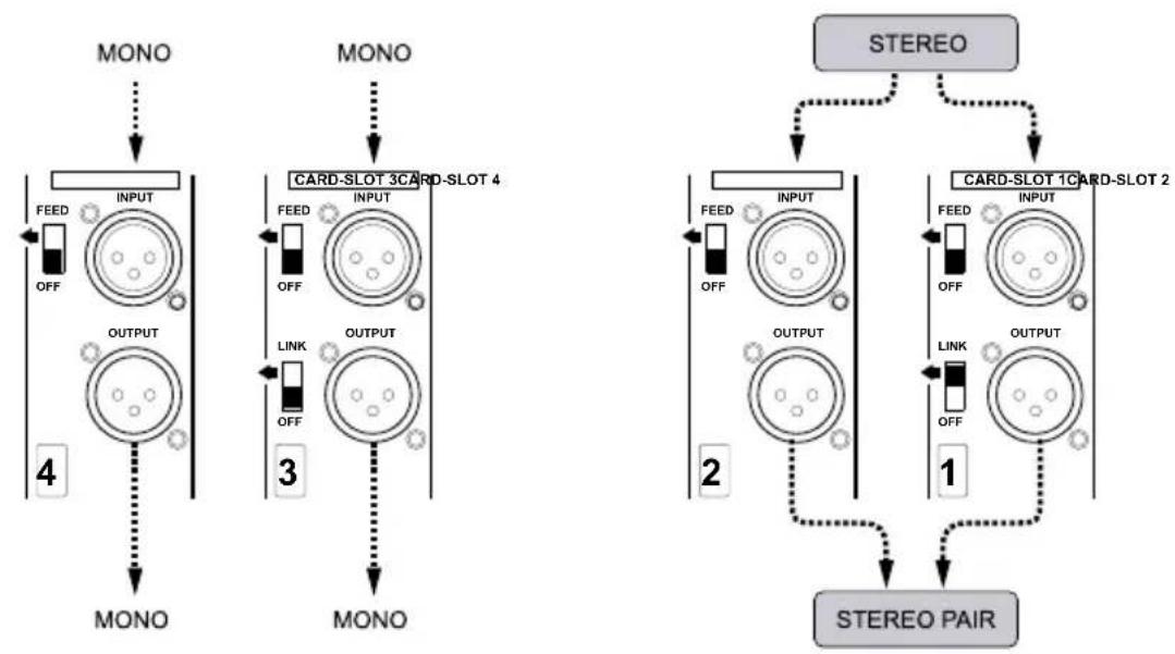
Odd numbered card-slots are equipped with a LINK switch. The LINK function allows modules that are ‘stereo ready’ to be linked together. A typical example would be using two limiters on a stereo track where you want the dynamics to be the same for both channels.
flowchart
graph TD
    subgraph STEREO
        direction TB
        A["MONO"] --> B["INPUT"]
        B --> C["FEED"]
        B --> D["OFF"]
        E["OUTPUT"] --> F["3"]
        G["LINK"] --> H["OUTPUT"]
        I["4"] --> J["MONO"]
    end

    subgraph CARD_SLOT_1
        direction TB
        K["STEREO"] --> L["INPUT"]
        L --> M["FEED"]
        L --> N["OFF"]
        O["OUTPUT"] --> P["3"]
        Q["LINK"] --> R["OUTPUT"]
        S["3"] --> T["MINI"]
        U["4"] --> V["MINI"]
    end

    subgraph CARD_SLOT_2
        direction TB
        W["STEREO"] --> X["INPUT"]
        X --> Y["FEED"]
        X --> Z["OFF"]
        AA["OUTPUT"] --> AB["3"]
        AC["LINK"] --> AD["OUTPUT"]
        AE["4"] --> AF["MINI"]
        AG["5"] --> AH["MINI"]
    end

    style STEREO fill:#f9f,stroke:#333
    style CARD_SLOT_1 fill:#ccf,stroke:#333
    style CARD_SLOT_2 fill:#ccf,stroke:#333
Link turned onLink turned off
OMNIPORT
Omniport™ is a special 14 " TRS jack located on the rear panel that has been left 'open' to allow the module to perform a unique task. In other words, depending on the type of module, the manufacturer can assign the Omniport to perform a function that may be most appropriate. This could be a key input on a gate, a TRS insert or maybe a buffered output. As the Omniport function is determined by the module, you will need to consult the module manufacturer's specification for details on how it was designed to be used.
Radial Modules Omniport Assignment:
Module Omniport function
PowerPre: Instrument input
JDV-Pre: Line level output (low-Z out for live touring)
X-Amp: Instrument input
PhazeQ: Balanced direct out (original dry signal out)
JDX: Direct box output (low-Z out for live touring)
EXTC: Send & receive insert for patch bay
Komit: Compressor key (side chain) input
Shuttle: Extra insert loop
Q3: TRS send & receive connection
Tank Driver: Second (alternate) spring reverb
PowerTube: Instrument input

POWER SUPPLY
The Powerhouse employs an external power supply that will automatically convert the various voltages used around the world and regulate them before sending the power to the Powerhouse. A standard male IEC/EIN power input connector makes it easy to travel as you will only need to change the cable to suit the local power connector type. The connection between the power supply is a 5-pin locking XLR.
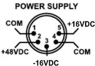
There is no power switch on the Powerhouse. As soon as you connect the power supply to the Powerhouse, a front panel LED will illuminate to let you know the power supply is active. This indicates the +16/-16V rails are ready. A second LED indicator will tell you that 48V phantom is also present. Phantom power is only sent to the modules when the supply connection to the 15-pin card slot is made. This will normally only be found on preamp modules that employ 48V phantom. Other modules will not be affected and will simply ignore the phantom power as if it were not there.
POWER SHARING
The power supply produces 1600 milliamps (mA) of current that is shared between the card-slots. So for instance, if you have power-hungry tube preamps in slots-1 thru 4 that require 250 milliamps of current each, you still have 600 milliamps of current left to power the other 6 card-slots. Considering most 500 series modules use between 40 and 130 milliamps of current, it is unlikely you will ever exceed the Powerhouse's available power.
Example:
| Slot-1 | Radial PowerTube tube preamp | Draw: 235mA |
| Slot-2 | Radial PowerTube tube preamp | Draw: 235mA |
| Slot-3 | Radial PowerTube tube preamp | Draw: 235mA |
| Slot-4 | Radial PowerTube tube preamp | Draw: 235mA |
| Slot-5 | Radial Komit compressor | Draw: 130mA |
| Slot-6 | Radial Komit compressor | Draw: 130mA |
| Slot-7 | Radial Q3 induction coil EQ | Draw: 25mA |
| Slot-8 | Radial Q3 induction coil EQ | Draw: 25mA |
| Slot-9 | Open | |
| Slot-10 | Open |
Total Current Draw: 1250mA (350mA to spare!)
Note: The original API™ spec calls for an average of 130mA for each slot. The Powerhouse exceeds this with an average 160mA of current divided equally between the ten card-slots.
INSTALLING MODULES IN THE POWERHOUSE
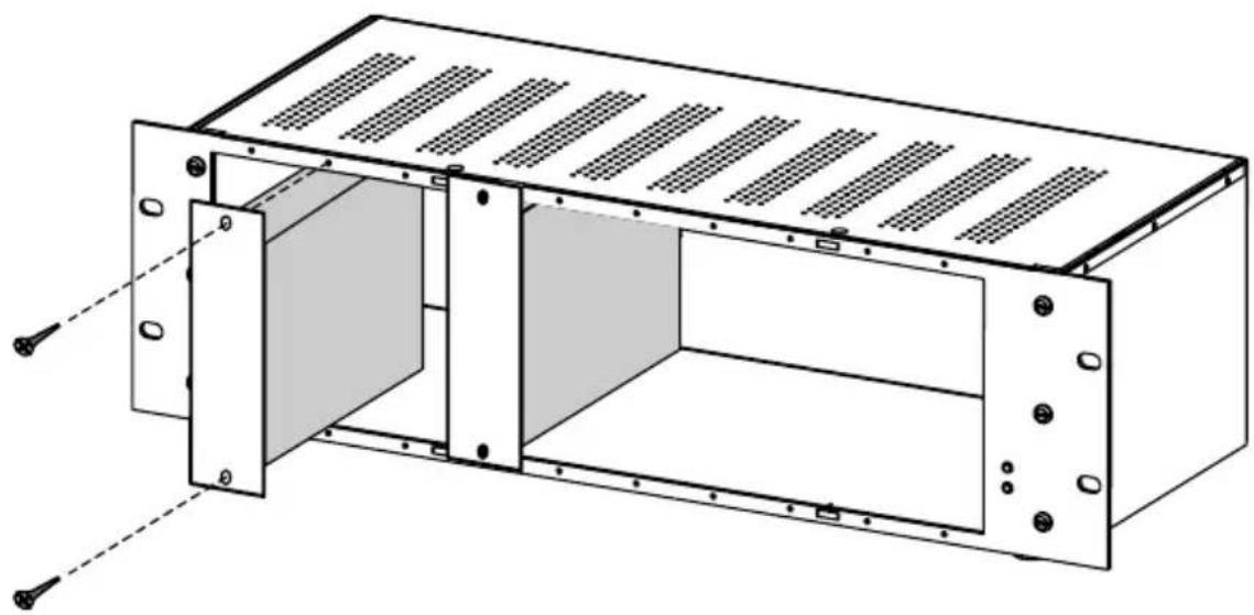
When making any electrical connection, it is always safer to do so with the power disconnected. The Powerhouse's internal power circuit is equipped with protective measures intended to provide a margin of safety should a module exchange be performed with the power on. However, the Powerhouse is not designed to allow repeated insertion and removal of modules while the power supply is active. Always power off the Powerhouse before exchanging modules. Modules slide into the Powerhouse card-slots and make contact with the 15-pin card edge receptacle on the inside rear plane. Once in place, modules are fastened using two 4/40 thread machine screws. Always secure the modules in place to ensure proper connection.
natural_image
Technical line drawing of a rectangular electronic enclosure with internal partition and mounting holes (no text or symbols)SIGNAL FLOW AND LEVELS
Because the Powerhouse is modular, it can accept a multitude of different devices into its card slots. This also means that you need to understand the signal flow so that you can be sure what you want to do will work. In the world of audio there are basically four low level signal groups to contend with before you get to high power output levels such as those produced by power amplifiers to drive loudspeakers.

-
MIC LEVEL RANGE: Microphones and direct boxes produce the weakest signals. These typically range from -60dB to -40dB depending on type. Some such as ribbon microphones can be as low as -70dB while condenser mics will generally be at the top end of this range. With a Powerhouse, one would connect a microphone to a preamp like the PowerPre™. This would elevate the mic-level signal to produce a +4dB line-level signal at the XLR output.
-
INSTRUMENT LEVEL RANGE: The output levels produced by instruments can range widely. A single coil electric guitar can produce as little as -40dB while an electronic keyboard, sampler or digital piano is capable of producing -10dB or more. For low level instruments, 500 series modules like the JDV™ amplify the signal to produce a +4dB signal level at the XLR output for direct recording.
-
UNBALANCED -10dB LINE LEVEL RANGE: Unbalanced outputs from CD players, keyboards, mixers and home hi-fi components are usually specified at -10dB and are often referred to as consumer line-level. These normally connect to a preamp input or a line level module. If too loud, one simply engages a pad.
-
BALANCED +4dB LINE LEVEL RANGE: This is the professional line level that comes from a recording system and is normally the level that connects in and out of EQs, compressors and so on. Most 500 series modules employ a +4dB signal level.
Matching the output level of one device to the input of the next will help you avoid distortion and maximize signal-to-noise. For instance, using a +4dB output to drive a -10dB input could overload the input and cause distortion. Conversely, a -10dB output may not have enough gain to drive the input of a +4dB device resulting in a higher noise floor.
Because each of the Powerhouse slots is equipped with a balanced line level input and a balanced line level direct output (depending on the module), you are pretty much free to interconnect modules or route signals to other devices using standard patch cables. Once you start working with the Powerhouse, you will quickly come to understand all of the capabilities and how easy it is to use.
USING THE POWERHOUSE
Because the Powerhouse is a modular frame, there are practically no limits as to what kind of signal chain you can create. For instance, it can be loaded with Radial modules set up for analog effects routing for your workstation, a customizable channel strip, an instrument preamp for live recording or as part of a play-back and overdub system.
As with all electronic equipment, turn off the power and turn down levels before making connections. This will avoid the loud on-off transient that can damage equipment or blow speakers. Plugging in a module is merely a matter of sliding it into the Powerhouse and carefully aligning the 15-pin card edge connector. Once plugged in, secure the module in place using the supplied Phillips screws. After the module is connected, it will automatically route the signal from the rear panel connectors to and from the module.
Simple XLR I/O
The first step in approaching the Powerhouse is going back to the original Lunchbox™. This device was basically a steel enclosure that fed power to a number of modules. Connecting to and from modules was done using the XLR connector that was associated with each card slot. The Powerhouse retains all of this connectivity while adding the convenience of 1/4" TRS connectors.

Setting Up A Channel Strip
The next stage is using several modules together to create a channel strip. For instance, when recording a vocal track, you may want to run a mic preamp into an EQ to add some presence and then into a compressor-limiter so that the track stays out of the 'red'.
Using the old system, you would connect the microphone to the mic preamp using a standard XLR cable. The mic preamp output would then connect to the EQ which in turn would connect to the limiter. The direct XLR output from the limiter would then be sent to the recording system.
flowchart
graph LR
    A["OUTPUT"] --> B["CARD SLOT 1"]
    B --> C["OUTPUT"]
    B --> D["OUTPUT"]
    B --> E["OUTPUT"]
    B --> F["OUTPUT"]
    B --> G["OUTPUT"]
    B --> H["OUTPUT"]
    B --> I["OUTPUT"]
    B --> J["OUTPUT"]
    B --> K["OUTPUT"]
    B --> L["OUTPUT"]
    B --> M["OUTPUT"]
    B --> N["OUTPUT"]
    B --> O["OUTPUT"]
    B --> P["OUTPUT"]
    B --> Q["OUTPUT"]
    B --> R["OUTPUT"]
    B --> S["OUTPUT"]
    B --> T["OUTPUT"]
    B --> U["OUTPUT"]
    B --> V["OUTPUT"]
    B --> W["OUTPUT"]
    B --> X["OUTPUT"]
    B --> Y["OUTPUT"]
    B --> Z["OUTPUT"]
    B --> AA["OUTPUT"]
    B --> AB["OUTPUT"]
    B --> AC["OUTPUT"]
    B --> AD["OUTPUT"]
    B --> AE["OUTPUT"]
    B --> AF["OUTPUT"]
    B --> AG["OUTPUT"]
    B --> AH["OUTPUT"]
    B --> AI["OUTPUT"]
    B --> AJ["OUTPUT"]
    B --> AK["OUTPUT"]
    B --> AL["OUTPUT"]
    B --> AM["OUTPUT"]
    B --> AN["OUTPUT"]
    B --> AO["OUTPUT"]
    B --> AP["OUTPUT"]
    B --> AQ["OUTPUT"]
    B --> AR["OUTPUT"]
    B --> AS["OUTPUT"]
    B --> AT["OUTPUT"]
    B --> AU["OUTPUT"]
    B --> AV["OUTPUT"]
    B --> AW["OUTPUT"]
    B --> AX["OUTPUT"]
    B --> AY["OUTPUT"]
    B --> AZ["OUTPUT"]
    B --> BA["OUTPUT"]
    B --> BB["OUTPUT"]
    B --> BC["OUTPUT"]
    B --> BD["OUTPUT"]
    B --> BE["OUTPUT"]
    B --> BF["OUTPUT"]
    B --> BG["OUTPUT"]
    B --> BH["OUTPUT"]
    B --> BI["OUTPUT"]
    B --> BJ["OUTPUT"]
    B --> BK["OUTPUT"]
    B --> BL["OUTPUT"]
    B --> BM["OUTPUT"]
    B --> BN["OUTPUT"]
    B --> BO["OUTPUT"]
    B --> BP["OUTPUT"]
    B --> BQ["OUTPUT"]
    B --> BR["OUTPUT"]
    B --> BS["OUTPUT"]
    B --> BT["OUTPUT"]
    B --> BU["OUTPUT"]
    B --> BV["OUTPUT"]
    B --> BW["OUTPUT"]
    B --> BX["OUTPUT"]
    B --> BY["OUTPUT"]
    B --> BZ["OUTPUT"]
    B --> CA["OUTPUT"]
    B --> CB["OUTPUT"]
    B --> CC["OUTPUT"]
    B --> CD["OUTPUT"]
    B --> CE["OUTPUT"]
    B --> CF["OUTPUT"]
    B --> CG["OUTPUT"]
    B --> CH["OUTPUT"]
    B --> CI["OUTPUT"]
    B --> CJ["OUTPUT"]
    B --> CK["OUTPUT"]
    B --> CL["OUTPUT"]
    B --> CM["OUTPUT"]
    B --> CN["OUTPUT"]
    B --> CO["OUTPUT"]
    B --> CP["OUTPUT"]
    B --> CQ["OUTPUT"]
    B --> CR["OUTPUT"]
    B --> CS["OUTPUT"]
    B --> CT["OUTPUT"]
    B --> CU["OUTPUT"]
    B --> CV["OUTPUT"]
    B --> CW["OUTPUT"]
MIC PREAMPEQUALIZERCOMPRESSOR
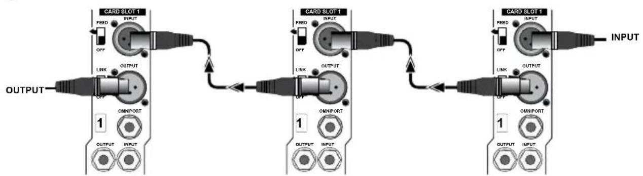
The Powerhouse simplifies the process with a FEED switch that replaces inter-module patch cables. Instead of using an XLR cable, you simply push the FEED switch into the UP position and it routes the signal to the adjoining module's input. When engaged, the FEED function sends the signal to the next module working from left to right (front view). Because the FEED function is tied to the XLR connector, it will work with new Radial modules and older 500 series modules.

flowchart
graph TD
    A["OUTPUT"] --> B["CARD SLOT 1"]
    B --> C["FEED INPUT"]
    B --> D["OFF"]
    B --> E["LINK OUTPUT"]
    B --> F["OFF OMPORT"]
    B --> G["OUTPUT INPUT"]
    H["FEED FEED"] --> I["CARD SLOT 1"]
    I --> J["FEED INPUT"]
    I --> K["OFF"]
    I --> L["LINK OUTPUT"]
    I --> M["OFF OMPORT"]
    I --> N["OUTPUT INPUT"]
    O["INPUT"] --> P["CARD SLOT 1"]
    P --> Q["FEED INPUT"]
    P --> R["OFF"]
    P --> S["LINK OUTPUT"]
    P --> T["OFF OMPORT"]
    P --> U["OUTPUT INPUT"]
Once you get started, you will soon find all kinds of new and exciting ways to patch modules. You could, for instance, use the feed switch to connect one module into the next while using a TRS cable to simultaneously patch the signal to third module card-slot. The image below shows how this is done. The mic signal has been split into two signal paths that can be processed separately.

flowchart
graph TD
    A["Microphone"] --> B["1"]
    B --> C["OUTPUT INPUT"]
    B --> D["1"]
    D --> E["OUTPUT INPUT"]
    D --> F["1"]
    F --> G["OUTPUT INPUT"]
    G --> H["1"]
    H --> I["OUTPUT INPUT"]
    I --> J["1"]
    J --> K["OUTPUT INPUT"]
    K --> L["1"]
    L --> M["OUTPUT INPUT"]
    M --> N["1"]
    N --> O["OUTPUT INPUT"]
    O --> P["1"]
    P --> Q["OUTPUT INPUT"]
    Q --> R["1"]
    R --> S["OUTPUT INPUT"]
    S --> T["1"]
    T --> U["OUTPUT INPUT"]
    U --> V["1"]
    V --> W["OUTPUT INPUT"]
    W --> X["1"]
    X --> Y["OUTPUT INPUT"]
    Y --> Z["1"]
    Z --> AA["OUTPUT INPUT"]
    AA --> AB["1"]
    AB --> AC["OUTPUT INPUT"]
    AC --> AD["1"]
    AD --> AE["OUTPUT INPUT"]
    AE --> AF["1"]
    AF --> AG["OUTPUT INPUT"]
    AG --> AH["1"]
    AH --> AI["OUTPUT INPUT"]
    AI --> AJ["1"]
    AJ --> AK["OUTPUT INPUT"]
    AK --> AL["1"]
    AL --> AM["OUTPUT INPUT"]
    AM --> AN["1"]
    AN --> AO["OUTPUT INPUT"]
    AO --> AP["1"]
    AP --> AQ["OUTPUT INPUT"]
    AQ --> AR["1"]
    AR --> AS["OUTPUT INPUT"]
    AS --> AT["1"]
    AT --> AU["OUTPUT INPUT"]
    AU --> AV["1"]
    AV --> AW["OUTPUT INPUT"]
    AW --> AX["1"]
    AX --> AY["OUTPUT INPUT"]
    AY --> AZ["1"]
SPECIFICATIONS\*
Circuit type: Connection buss from modules to connectors
Format: 19" rack mount, 3 rack space
Number of slots: 10
Input connectors: 10 balanced XLR male, 10 14 " TRS
Output connectors: 10 balanced XLR female, 10 14 " TRS
Compatibility: Adheres to the Whos-Doc and VPR Alliance
Functions
Omniport:......Yes, TRS I/O jack, module dependent
Feed switch: Yes, feeds input of adjacent module
Stereo link: Yes, links two stereo compatible modules
48V phantom power: Yes, on all channels
Electrical
Available current: 1600 milliamps
Average current....160 mA per slot (all slots used)
Card slot impedance: Module dependent
Ground connections: ....Chassis & audio ground
XLR pin wiring: ......AES standard: pin-1 ground, pin-2 (+), pin-3 (-)
Power supply: External 100V - 240V AC with 48V Phantom
PSU Connection: Locking 5 pin XLR female on cable
Product Size (W x H x L)....19" x 5.25" x 7.5" (482mm x 133mm x 190mm)
Product Weight 15.3lbs / 6.9kg (without modules)
Conditions:...... For use in dry locations only between 5°C and 40°C
*Specifications are subject to change without notice.
THIS PAGE LEFT BLANK
THREE YEAR TRANSFERABLE LIMITED WARRANTY
RADIAL ENGINEERING LTD. ("Radial") warrants this product to be free from defects in material and workmanship and will remedy any such defects free of charge according to the terms of this warranty. Radial will repair or replace (at its option) any defective component(s) of this product (excluding finish and wear and tear on components under normal use) for a period of three (3) years from the original date of purchase. In the event that a particular product is no longer available, Radial reserves the right to replace the product with a similar product of equal or greater value. In the unlikely event that a defect is uncovered, please call 604-942-1001 or email service@radialeng.com to obtain an RA number (Return Authorization number) before the 3 year warranty period expires. The product must be returned prepaid in the original shipping container (or equivalent) to Radial or to an authorized Radial repair center and you must assume the risk of loss or damage. A copy of the original invoice showing date of purchase and the dealer name must accompany any request for work to be performed under this limited and transferable warranty. This warranty shall not apply if the product has been damaged due to abuse, misuse, misapplication, accident or as a result of service or modification by any other than an authorized Radial repair center.
THERE ARE NO EXPRESSED WARRANTIES OTHER THAN THOSE ON THE FACE HEREOF AND DESCRIBED ABOVE. NO WARRANTIES WHETHER EXPRESSED OR IMPLIED, INCLUDING BUT NOT LIMITED TO, ANY IMPLIED WARRANTIES OF MERCHANTABILITY OR FITNESS FOR A PARTICULAR PURPOSE SHALL EXTEND BEYOND THE RESPECTIVE WARRANTY PERIOD DESCRIBED ABOVE OF THREE YEARS. RADIAL SHALL NOT BE RESPONSIBLE OR LIABLE FOR ANY SPECIAL, INCIDENTAL OR CONSEQUENTIAL DAMAGES OR LOSS ARISING FROM THE USE OF THIS PRODUCT. THIS WARRANTY GIVES YOU SPECIFIC LEGAL RIGHTS, AND YOU MAY ALSO HAVE OTHER RIGHTS, WHICH MAY VARY DEPENDING ON WHERE YOU LIVE AND WHERE THE PRODUCT WAS PURCHASED.

True to the Music
www.radialeng.com
Radial Engineering Ltd.
1588 Kebet Way, Port Coquitlam BC V3C 5M5
tel: 604-942-1001 • fax: 604-942-1010
info@radialeng.com • www.radialeng.com


- Workhorse™ Powerhouse™
- User Guide
- IMPORTANT SAFETY & USER NOTICE - FOR PROFESSIONAL USE
- SAFETY NOTICE - NO HOT SWAPPING OF MODULES
- Radial® Workhorse™ Powerhouse™
- Series Power Rack
- Table of Contents Page
- FRONT PANEL FEATURE SET
- REAR PANEL FEATURE SET
- INTRODUCTION
- CARD SLOT I/O CONNECTIONS
- FEED SWITCH
- STEREO LINK SWITCH
- OMNIPORT
- Radial Modules Omniport Assignment:
- Module Omniport function
- POWER SUPPLY
- POWER SHARING
- INSTALLING MODULES IN THE POWERHOUSE
- SIGNAL FLOW AND LEVELS
- USING THE POWERHOUSE
- Simple XLR I/O
- Setting Up A Channel Strip
- SPECIFICATIONS\*
- Functions
- Electrical
- THREE YEAR TRANSFERABLE LIMITED WARRANTY
Brand : Radial Engineering
Model : Workhorse Powerhouse
Category : Rack audio