WJ-PU201 - Network card / adapter i-PRO - Free user manual and instructions
Find the device manual for free WJ-PU201 i-PRO in PDF.


| Product Type | Network Card / Adapter |
| Brand | i-PRO |
| Model | WJ-PU201 |
| Interface | PCI Express |
| Data Transfer Rate | 1000 Mbps |
| Connector Type | RJ-45 |
| Power Consumption | 5 W (max) |
| Operating Temperature | 0°C to 50°C |
| Dimensions (W x H x D) | 120 x 20 x 90 mm |
| Weight | 100 g |
| Compatibility | Windows, Linux, i-PRO cameras |
| LED Indicators | Link, Activity, Power |
| Mounting | Low-profile bracket included |
| Certifications | CE, FCC |
| Features | Gigabit Ethernet, Jumbo Frame support, Wake-on-LAN |
| Maintenance | Clean with dry cloth; avoid liquids |
| Safety | Use only in dry environment; avoid static discharge |
| Spare Parts & Repairability | No user-serviceable parts; contact i-PRO support |
Frequently Asked Questions - WJ-PU201 i-PRO
User questions about WJ-PU201 i-PRO
0 question about this device. Answer the ones you know or ask your own.
Ask a new question about this device
Download the instructions for your Network card / adapter in PDF format for free! Find your manual WJ-PU201 - i-PRO and take your electronic device back in hand. On this page are published all the documents necessary for the use of your device. WJ-PU201 by i-PRO.
USER MANUAL WJ-PU201 i-PRO
Operating Instructions
Included Installation Instructions
PoE Camera Power Unit For professional use only
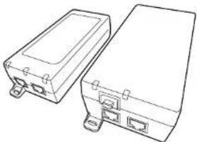
Model No. WJ-PU201 WJ-PU201/G WJ-PU201F/G
natural_image
Line drawing of two electronic device enclosures with ports and connectors (no text or symbols)WJ-PU201 WJ-PU201F/G
- Before attempting to connect or operate this product, please read these instructions carefully and save this manual for future use.
- The external appearance and other parts shown in this manual may differ from the actual product within the scope that will not interfere with normal use due to improvement of the product.
i-PRO Co., Ltd. assumes no responsibility for injuries or property damage resulting from failures arising out of improper installation or operation inconsistent with this documentation.
*

i-PRO Co., Ltd.
Tokyo, Japan https://www.i-pro.com/
Authorised Representative in EU: I-PRO EMEA B.V. Laarderhoogtweg 25, 1101 EB Amsterdam, Netherlands
i-PRO EMEA B.V. UK Branch 1010 Cambourne Business Park, Cambridgeshire CB23 6DP


© I-PRO Co., Ltd. 2022
avs0322-2062 Printed in China
Disposal of Old Equipment
Only for European Union and countries with recycling systems
This symbol on the products, packaging, and/or accompanying documents means that used electrical and electronic products must not be mixed with general household waste. For proper treatment, recovery and recycling of old products, please take them to applicable collection points in accordance with your national legislation. By disposing of them correctly, you will help to save valuable resources and prevent any potential negative effects on human health and the environment. For more information about collection and recycling, please contact your local municipality. Penalties may be applicable for incorrect disposal of this waste, in accordance with national legislation.
—For U.S.A.
Note: This equipment has been tested and found to comply with the limits for a Class B digital device, pursuant to part 15 of the FCC Rules. These limits are designed to provide reasonable protection against harmful interference in a residential installation. This equipment generates, uses and can radiate radio frequency energy and, if not installed and used in accordance with the instructions, may cause harmful interference to radio communications. However, there is no guarantee that interference will not occur in a particular installation. If this equipment does cause harmful interference to radio or television reception, which can be determined by turning the equipment off and on, the user is encouraged to try to correct the interference by one or more of the following measures: - Reorient or relocate the receiving antenna. - Increase the separation between the equipment and receiver. - Connect the equipment into an outlet on a circuit different from that to which the receiver is connected. - Consult the dealer or an experienced radio/TV technician for help.
FCC CAUTION Changes or modifications not expressly approved by the party responsible for compliance could void the user's authority to operate the equipment.
Supplier's Declaration of conformity
Trade name : i-PRO Model No. : WJ-PU201/ WJ-PU201F Responsible Party : i-PRO Americas Inc. 8550 Fallbrook Drive, Suite 200 Houston, Texas 77064 Support Contact : 1-800-513-5417

—For U.S.A.
The model number and serial number of this product may be found on the surface of the unit. You should note the model number and serial number of this unit in the space provided and retain this book as a permanent record of your purchase to aid identification in the event of theft. Model No____ Serial No____
—For U.S.A.
This device complies with part 15 of the FOC Rules. Operation is subject to the following two conditions: (1) This device may not cause harmful interference, and (2) this device must accept any interference received, including interference that may cause undesired operation.
— For Canada
CAN ICES-3(B)/NMB-3(B)
FOR YOUR SAFETY PLEASE READ THE FOLLOWING TEXT CAREFULLY.
This appliance is supplied with a mounted three pin mains plug for your safety and convenience. A 5 amp fuse is fitted in this plug. Should the fuse need to be replaced please ensure that the replacement fuse has a rating of 5 amp and that it is approved by ASTA or BSI to BS1362. Check for the ASTA mark up or the BSI mark on the body of the fuse. If the plug contains a removable fuse cover you must ensure that it is refitted when the fuse is replaced. If you lose the fuse cover the plug must not be used until a replacement cover is obtained. A replacement fuse cover can be purchased from our dealer.
IF THE FITTED MOULDED PLUG IS UNSUITABLE FOR THE SOCKET OUTLET IN YOUR HOME THEN THE FUSE SHOULD BE REMOVED AND THE PLUG CUT OFF AND DISPOSED OF SAFELY. THERE IS A DANGER OF SEVERE ELECTRICAL SHOCK IF THE CUT OFF PLUG IS INSERTED INTO ANY 13 AMP SOCKET.
How to replace the fuse
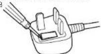
The location of the differs according to the type of AC mains plug (figures A and B). Confirm the AC mains plug fitted and follow the instructions below. Illustrations may differ from actual AC mains plug. Open the fuse cover with a screwdriver and replace the fuse and close or attach the fuse cover.
Figure A
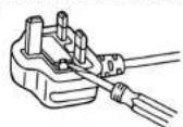
Figure B
Product outline
This unit is a PoE camera power unit that enables i-PRO network cameras to operate by supplying power from a network cable. For the latest information on supported cameras, refer to our technical information website
WARNING:
- All work related to the installation and earthing of this product should be made by qualified service personnel or system installers.
Caution:
- The network camera is only intended for a connection to an ethernet or PoE network without routing to the outside plant.
• The socket-outlet shall be easily accessible. - Only use the included AC cord.
- Do not use the included AC cord with other devices.
- Shielded (STP) LAN cables must be used with this unit to ensure compliance with EMC standards.
- Before attempting to connect or operate this product, please read these instructions carefully.
Notice:
• This product is not suitable for use in locations where children are likely to be present.
• This product is a professional equipment.
- This product must be connected to a grounded outlet. - Apparalels slikprop skal tilskuttes en stikkontakt med
jord, som giver forbindelse II stikproppens jord.
Direct current symbol

Alternation current symbol

For indoor use only
Precautions
■ Do not insert any foreign objects.
Fire or electrical shock may be caused if water or any foreign objects, such as metal objects, enter inside the unit.
Turn the power off immediately and contact qualified service personnel for service.
■ Do not use this product in an inflammable atmosphere.
Failure to observe this may cause an explosion resulting in injury.
■ Do not strike or give a strong shock to this product.
Failure to observe this may cause injury or fire.
■ Do not damage the power cord.
Do not damage, fabricate, twist, stretch, bundle, or forcibly bend the power cord. Do not place heavy objects on it, and keep it away from heat sources.
Use of a damaged power cord may cause electric shock, short circuit, or fire.
Consult the dealer for repair.
■ Do not forcibly pull on the cable.
Doing so may result in a fire or electric shock.
■ Do not place containers with liquids such as water on the product.
Liquids such as water getting inside may cause fire or electric shock.
Disconnect the power plug immediately and contact your dealer
■ Never touch the power plug with wet hands.
This may result in electric shock.
■ Do not attempt to disassemble or modify this product.
Failure to observe this may cause fire or electric shock. Consult the dealer for the repair or inspections.
■ Do not install or clean the camera, or touch this product, the power cord or the connected cables during thunder storms.
Failure to observe this may cause electric shock.
■ Refer installation work to the dealer.
Installation work requires technique and experience. Failure to observe this may cause fire, electric shock, injury, or damage to the product. Be sure to consult the dealer.
■ Stop the operation immediately when something is wrong with this product.
Using it as is while there is smoke or a smell may cause damage.
Disconnect the power plug immediately and contact your dealer.
■ Turn the power off when do wirning of this product.
Failure to observe this may cause electric shock. In addition, short circuit or wrong wiring may cause fire.
■ Correctly perform all wiring.
Short circuits in the wiring or incorrect wiring may cause fire or electric shock.
■ Turn the power off when cleaning this product.
Failure to observe this may cause electrical shock.
■ Completely insert the power plug into the power outlet.
Failure to do so may cause electric shock and/or excessive heat resulting in a fire.
Do not use damaged power plugs or power outlets.
■ Always hold the plug when unplugging the power cord.
Otherwise, the cord may be damaged and result in a fire or electric shock.
■ Regularly remove any dust, etc. from the power plug.
Accumulated dust may cause an insulation defect from moisture, etc., resulting in a fire.
Disconnect the power plug, then wiping with a dry cloth.
■ If you do not use the unit for a long period of time, unplug the power cord from the receptacle.
Otherwise, it may result in a fire or electric shock.
About notations
The following notations are used when describing the functions limited for specified models.
The functions without the notations are supported by all models.

The functions with this notation are available when using the model WJ-PU201, WJ-PU201/G.

The functions with this notation are available when using the model WJ-PU201F/G.
Specifications
| Power source: 100 to 240 V AC (50 Hz/60 Hz) | |
| Input power consumption: | PUJ201-P 2.0 A (RMS) max for 90 V AC, 1.2 A (RMS) max for 240 V AC PUJ201-F 2.0 A (RMS) max for 90 V AC, 1.0 A (RMS) max for 240 V AC |
| Output power consumption: 56 V | DC: Approx. 1.07 A / 60 W(Combined output on data pairs and spare pairs.) |
| Operating environmentAmbient operating temperature: | 60 W output: -10 °C to +10 °C {14 °F to 104 °F}30 W output: -10 °C to +50 °C {14 °F to 122 °F} |
| Ambient operating humidity: 10 % to 90 % (no condensation) | |
| Strage environmentStorage temperature: -20 °C to | +65 °C {-4 °F to +149 °F} |
| Storage humidity: 10 % to 90 % (no condensation) | |
| Network: 10BASE-T/100BASE-TX/1000BASE-T, RJ45 connector (×2)Compliant with IEEE802.3ot/at/af Standard PUJ201-F Standard SFP module port (LC type) (×1) | |
| AC Input: IEC320 (C14) | |
| Dimension:(excluding power cord/cables) | PUJ201-P 85 mm (W) × 36 mm (-H) × 163 mm (D){2-9/16 inches (W) × 1-13/32 inches (-H) × 6-13/32 inches (D)} PUJ201-F 80 mm (W) × 50 mm (-H) × 184 mm (D){3-5/32 inches (W) × 1-31/32 inches (-H) × 7-1/4 inches (D)}(excluding cord and plag) |
| Mass: | PUJ201-P Approx. 300 g {0.66 lbs} PUJ201-F Approx. 465 g {1.03 lbs} |
| Finish: PC/ABS resin, Matte black | |
Standard accessories
| Operating Instructions (this document) | 1 pc. |
| Power cord (A type) | 1 pc. |
| Power cord (C type) (BF type) | each 1 pc. |
Precautions for installation
■ This product is designed to be used indoors
This product is not operable outdoors. Do not expose this product to direct sunlight for hours and do not install the product near a heater or an air conditioner. Otherwise, it may cause deformation, discoloration and malfunction. Keep this product away from water and moisture.
■ Equipment classification and power source indication label
Refer to the indication label of this unit for the equipment classification, power source, and other information.
Parts and functions
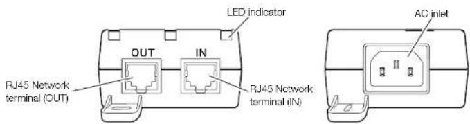
■ LED Indicators
• Power failure
• POE power ready but no connection
• POE output power good
• POE detection failure
• POE output over power or short
- Invalid load condition
Lights amber short/slow Blinking
Lights green
Lights Amber/Green alternate blinking
Lights amber long/fast blinking
Blinks green
Lights off
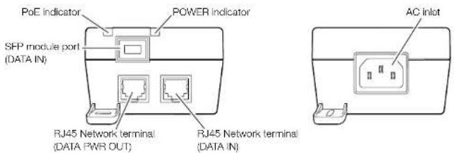
■ LED Indicators
POWER indicator:
• Power failure
• AC Power Good Lights green
• POE power ready but no connection
• POE output power good
- Unit is in Over Load Condition
or Unit has detected an Invalid Load
Lights green
Lights amber short/slow Blinking
Lights green
Lights red
Lights off
Making connections
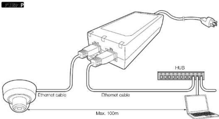
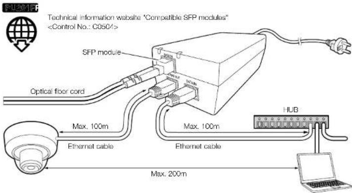
IMPORTANT:
- For the Ethernet cable, use a shielded network cable (STP) CAT5e or higher.
- Make sure that the cable length from the RJ45 network terminal (OUT/DATA PWR OUT) to the camera is 100 m or loss.
- When using a splitter, connect it at a point close to the camera, not the PoE Camera Power Unit side.
- Use this unit on a flat table without securing it in place with screws. Do not secure it in place on a ceiling or wall with screws.
Troubleshooting
Before asking for repairs, check the symptoms with the following table.
Contact your dealer if a problem cannot be solved even after checking and trying the solution in the table or a problem is not described below.
| Symptom | Cause/solution | Reference pages |
| The PoE Camera Power Unit does not turn on. | LED indicator PU230P and POWER indicator PU231F do not light or blink.Make sure that the power cord is properly connected to this unit.Make sure that the voltage of the outlet is 100 to 240 V AC. | Parts and functions |
| The camera connected to the PoE Camera Power Unit does not turn on. | LED indicator PU230P and POWER indicator PU231F do not light green.Make sure that the input Ethernet cable is connected to the RJ45 network terminal (IN/DATA IN), and the camera side is connected to the RJ45 network terminal (OUT/DATA PWR OUT).Make sure that the unit and the camera are connected with a straight network cable of STP CAT5 or higher.Make sure that the twisted pair cable or RJ45 connector is not short-circuited.If you are using a power splitter, make sure it is working properly. | Making connections |
| The camera connected to the PoE Camera Power Unit turns on, but a data link is not established. | LED indicator PU230P and POWER indicator PU231F blink Ambor/Groon.Make sure that the unit and the camera are connected with a straight network cable of STP CAT5 or higher.If you are using an RJ45 Ethernet cable, make sure the length of the cable from the HUB to the camera is less than 100 m.If you are using a power splitter, make sure it is working properly. | - |
| Image data cannot be transmitted by the optical fiber cord PU230FP | Make sure that the SFP module is installed correctly in this unit.Make sure that the connector of the optical fiber cord is appropriately connected to the SFP module.Check if the optical fiber cord appropriately operates by replacing the optical fiber cord with new one. | - |
- Operating Instructions
- PoE Camera Power Unit For professional use only
- i-PRO Co., Ltd.
- Disposal of Old Equipment
- FOR YOUR SAFETY PLEASE READ THE FOLLOWING TEXT CAREFULLY.
- IF THE FITTED MOULDED PLUG IS UNSUITABLE FOR THE SOCKET OUTLET IN YOUR HOME THEN THE FUSE SHOULD BE REMOVED AND THE PLUG CUT OFF AND DISPOSED OF SAFELY. THERE IS A DANGER OF SEVERE ELECTRICAL SHOCK IF THE CUT OFF PLUG IS INSERTED INTO ANY 13 AMP SOCKET.
- Product outline
- WARNING:
- Notice:
- Precautions
- About notations
- Standard accessories
- Precautions for installation
- ■ This product is designed to be used indoors
- ■ Equipment classification and power source indication label
- Parts and functions
- ■ LED Indicators
- Lights off
- POWER indicator:
- Making connections
- IMPORTANT:
- Troubleshooting
- Before asking for repairs, check the symptoms with the following table.
Brand : i-PRO
Model : WJ-PU201
Category : Network card / adapter