VP-81KSi - Audio/video switch Kramer - Free user manual and instructions
Find the device manual for free VP-81KSi Kramer in PDF.


| Product Type | 8x1 UXGA/Audio STEP-IN Switcher |
| Brand / Model | Kramer VP-81KSi |
| Inputs | 8 VGA on 15-pin HD (F) connectors; 8 unbalanced stereo audio on 3.5mm mini jacks |
| Outputs | 1 VGA on 15-pin HD (F); 1 TP on RJ-45; 1 unbalanced stereo audio on 3.5mm mini jack; 1 balanced stereo audio on 5-pin detachable terminal block |
| Bandwidth | Video: 440 MHz (VGA out), 150 MHz (CAT5 out); Audio: 20 kHz |
| Max. Resolution | VGA up to WUXGA (1920x1200) |
| Audio Volume Control | -65.4 to +25.8 dB (unbalanced), -59.4 to +31.8 dB (balanced) |
| Control Interfaces | Front panel buttons, IR remote, RS-232, RS-485, Ethernet (web browser), contact closure, SI-1VGA step-in module |
| Power Source | 100-240 V AC, 50/60 Hz, 29 VA |
| Dimensions (W x D x H) | 43.6 cm x 19.1 cm x 4.4 cm (19" x 7.5" x 1U) |
| Weight | Approx. 1.7 kg (3.8 lbs) |
| Operating Temperature | 0° to +40°C (32° to 104°F) |
| Storage Temperature | -40° to +70°C (-40° to 158°F) |
| Humidity | 10% to 90%, RHL non-condensing |
| Main Functions | 8x1 switching of video (UXGA) and stereo audio; audio-follow-video or breakaway mode; volume control; cascading up to 8 units for 57 inputs; RS-232/485/Ethernet control; IR remote; EDID management |
| Maintenance | No user-serviceable parts inside; disconnect power before cleaning; use dry cloth for exterior |
| Safety | Use only provided power cord; avoid moisture and excessive heat; do not open unit; disconnect power when servicing |
| Spare Parts / Repairability | No user-replaceable parts; contact Kramer authorized service for repairs; fuse replacement as per product label |
| Included Accessories | Power cord, RC-IR3 IR remote, one SI-1VGA step-in module, user manual |
| Warranty | 7 years limited warranty (check website for latest) |
Frequently Asked Questions - VP-81KSi Kramer
User questions about VP-81KSi Kramer
0 question about this device. Answer the ones you know or ask your own.
Ask a new question about this device
Download the instructions for your Audio/video switch in PDF format for free! Find your manual VP-81KSi - Kramer and take your electronic device back in hand. On this page are published all the documents necessary for the use of your device. VP-81KSi by Kramer.
USER MANUAL VP-81KSi Kramer
Kramer Electronics, Ltd.

USER MANUAL
Model:
VP-81KSi
8x1 UXGA/Audio STEP-IN Switcher
Contents
1 Introduction 1
2 Getting Started 1
2.1 Quick Start 1
3 Overview 3
3.1 Defining EDID 4
4 Defining the VP-81KSi 8x1 UXGA/Audio STEP-IN Switcher 5
4.1 Using the IR Transmitter for the VP-81KSi 7
5 Installing in a Rack 8
6 Connecting the VP-81KSi 8x1 UXGA/Audio STEP-IN Switcher 9
6.1 Connecting the Balanced/Unbalanced Stereo Audio Output 10
6.2 Connecting Remote Contact Closure Input Selection Switches 11
6.3 Connecting the SI-1VGA Remote Step-in Module 11
6.4 Connecting the AV ON CAT 5 Twisted Pair Output 12
6.5 Connecting to the VP-81KSi via the RS-232 Port 12
6.6 Connecting to the VP-81KSi via the RS-485 Port 13
6.6.1 Setting the RS-485 Machine Number and Bus Termination DIP-switches 13
6.6.2 Connecting and Controlling Multiple VP-81KSi Devices 14
6.7 Cascading Multiple VP-81KSi Devices 14
6.8 Controlling a Remote RS-232 Device 15
6.9 Connecting to the VP-81KSi via the Ethernet Port 16
6.9.1 Connecting Directly to the Ethernet Port 16
6.9.2 Connecting via a Network Hub, Switch, or Router 18
6.9.3 Configuring the Ethernet Port on the VP-81KSi 18
7 Operating the VP-81KSi Locally via the Front Panel Buttons 19
7.1 Using the Front Panel INPUT SELECTOR Buttons 19
7.2 Using the Audio-Follow-Video/Breakaway Modes 20
7.2.1 Operating in Breakaway Mode 20
7.2.2 Switching to Audio Follow Video Mode 20
7.3 Setting the Audio Output Gain 20
7.4 Operating Cascaded VP-81KSi Devices 20
8 Operating the VP-81KSi Remotely 21
9 Operating the VP-81KSi Remotely using a Web Browser 21
9.1 To Log On to the VP-81KSi Web Pages 22
9.2 The Switching Matrix Page 23
9.2.1 Switching an Input to an Output 24
9.2.2 Operating in the Confirm Mode 25
9.3 The Audio Gain Page 26
9.4 The Configurations Page 27
10 Upgrading the Firmware 28
11 EDID 28
12 Technical Specifications 29
13 Communication Parameters 30
14 Default EDID 30
15 Table of ASCII Codes for Serial Communication (Protocol 3000) 31
16 Table of Hex Codes for Serial Communication (Protocol 2000) 32
17 Kramer Protocol 33
17.1 Switching Protocols 34
17.1.1 Switching Protocols via the Front Panel Buttons 34
17.1.2 Switching Protocols via Protocol Commands 34
17.2 Kramer Protocol 3000 34
17.2.1 Protocol 3000 Syntax 34
17.2.2 Command Part Details 35
17.3 Kramer Protocol 2000 41
Figures
Figure 1: VP-81KSi 8x1 UXGA/Audio STEP-IN Switcher Front Panel 5
Figure 2: VP-81KSi 8x1 UXGA/Audio STEP-IN Switcher Rear Panel 6
Figure 3: Connecting the VP-81KSi 9
Figure 4: Balanced Stereo Audio Connection 10
Figure 5: Unbalanced Stereo Audio Connection 10
Figure 6: Remote Input Selection Switch Wiring 11
Figure 7: Connecting the SI-1VGA 12
Figure 8: RS-485 DIP-switches 13
Figure 9: Cascading up to Eight VP-81KSi Devices 15
Figure 10: Local Area Connection Properties Window 17
Figure 11: Internet Protocol (TCP/IP) Properties Window 17
Figure 12: Connect Window 18
Figure 13: Device Properties Window 19
Figure 14: Java Test Page Success Message 21
Figure 15: The Loading Page 22
Figure 16: First Time Security Warning 23
Figure 17: VP-81KSi Switching Matrix Page 24
Figure 18: Switching an Input to an Output 25
Figure 19: Switching an Input to an Output 25
Figure 20: Exiting Offline Warning 26
Figure 21: Audio Gain Page 26
Figure 22: Configurations Page 27
Tables
Table 1: VP-81KSi 8x1 UXGA/Audio STEP-IN Switcher Front Panel Features 5
Table 2: VP-81KSi 8x1 UXGA/Audio STEP-IN Switcher Rear Panel Features 6
Table 3: RS-485 DIP-switch Settings 13
Table 4: Machine Number DIP-switch Settings 14
Table 5: Button Illumination Descriptions 20
Table 6: Technical Specifications of the VP-81KSi 29
Table 7: Communication Parameters 30
Table 8: VP-81KSi Video and Audio Signal Codes 31
Table 9: VP-81KSi Audio Input Gain Codes 32
Table 10: VP-81KSi Audio and Audio Output Gain Codes 32
Table 11: VP-81KSi Hex Codes for Protocol 2000 32
Table 12: VP-81KSi Hex Codes that Increase/Decrease Audio Input Gain 32
Table 13: Hex Codes that Set the Audio Input Gain 33
Table 14: VP-8x8AK Hex Codes for Increasing/Decreasing the Output Gain 33
Table 15: Hex Codes for Setting the Audio Output Gain 33
Table 16: Instruction Codes for Protocol 3000 36
Table 17: Protocol Definitions 41
Table 18: Instruction Codes for Protocol 2000 42
1 Introduction
Welcome to Kramer Electronics! Since 1981, Kramer Electronics has been providing a world of unique, creative, and affordable solutions to the vast range of problems that confront the video, audio, presentation, and broadcasting professional on a daily basis. In recent years, we have redesigned and upgraded most of our line, making the best even better! Our 1,000-plus different models now appear in 14 groups ^1 that are clearly defined by function.
Congratulations on purchasing your Kramer VP-81KSi 8x1 UXGA/Audio STEP-IN Switcher.
The VP-81KSi is ideal for:
- Display systems requiring simple input selection
- Remote monitoring of computer activity in schools and businesses
- Rental/staging applications
• Multimedia and presentation source selection
The package includes the following items:
• VP-81KSi 8x1 UXGA/Audio STEP-IN Switcher
- Infrared RC-IR3 remote control transmitter (including the required battery and a separate user manual ^2 )
• One SI-1VGA Remote Step-in Module and user manual ^2
- Power cord
- This user manual ^2
2 Getting Started
We recommend that you:
- Unpack the equipment carefully and save the original box and packaging materials for possible future shipment
- Review the contents of this user manual
- Use Kramer high performance high resolution cables ^3
2.1 Quick Start
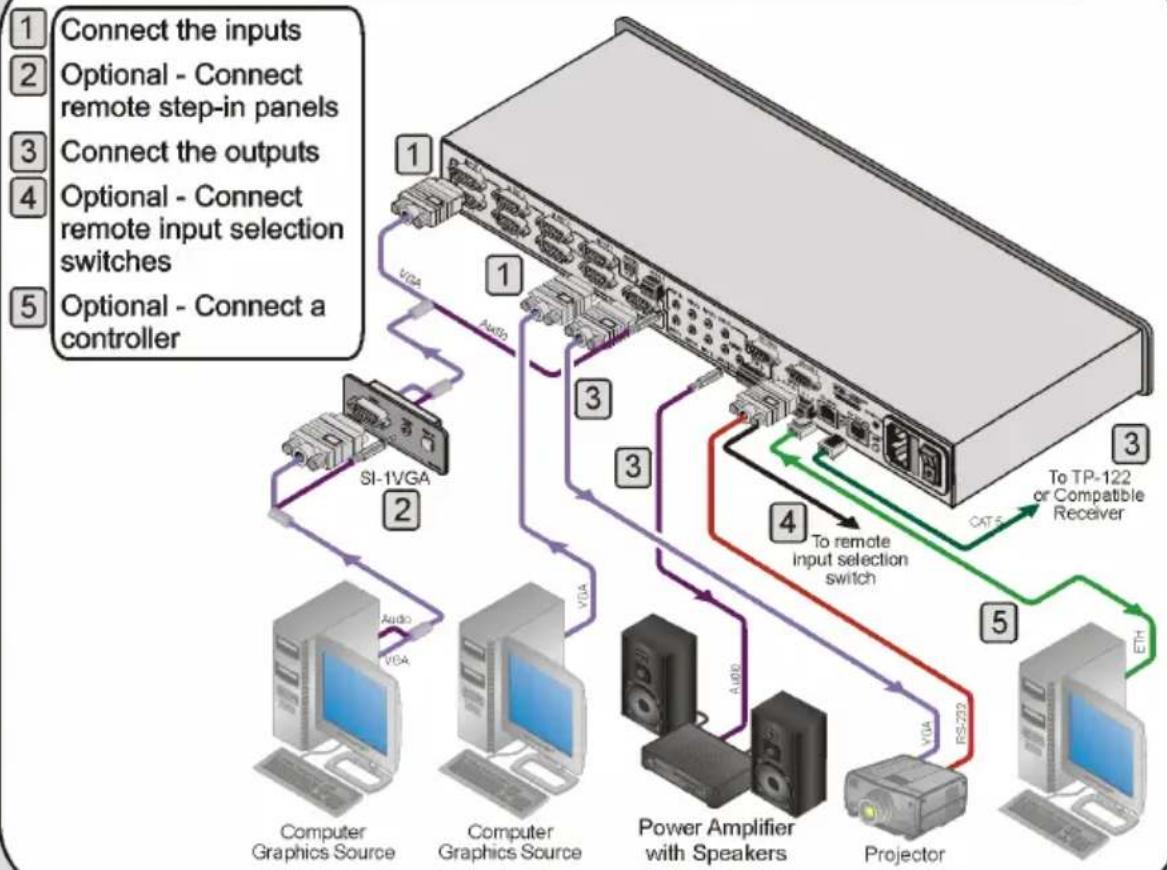
This quick start chart summarizes the basic setup and operation steps.
Step 1: Mount the machine - see Section 5
Mount the machine in a rack or stick the 4 rubber feet to the underside

Step 2: Connect the inputs and outputs - see Section 6
flowchart
graph TD
    A["Computer Graphics Source"] -->|Connect the inputs| B["SI-1VGA"]
    C["Computer Graphics Source"] -->|Connect the outputs| B
    D["Power Amplifier with Speakers"] -->|To remote input selection switch| E["Projector"]
    F["Optional - Connect a controller"] -->|Selects to TP-122 or Compatible Receiver| G["Projector"]
    B -->|Auto| H["Output"]
    B -->|Auto| I["Switch"]
    B -->|Auto| J["Switch"]
    B -->|Auto| K["Switch"]
    B -->|Auto| L["Switch"]
    B -->|Auto| M["Switch"]
    B -->|Auto| N["Switch"]
    B -->|Auto| O["Switch"]
    B -->|Auto| P["Switch"]
    B -->|Auto| Q["Switch"]
    B -->|Auto| R["Switch"]
    B -->|Auto| S["Switch"]
Step 3: Switch the power on
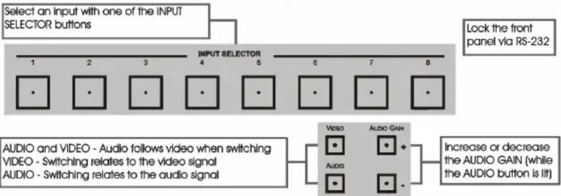
Step 4: Operate the machine - see Sections 7, 8 and 9
flowchart
graph TD
    A["Select an input with one of the INPUT SELECTOR buttons"] --> B["INPUT SELECTOR"]
    B --> C["1 2 3 4 5 6 7 8"]
    C --> D["•"]
    C --> E["•"]
    C --> F["•"]
    C --> G["•"]
    C --> H["•"]
    C --> I["•"]
    J["Lock the front panel via RS-232"] --> K["Video"]
    J --> L["Audio Gain"]
    M["AUDIO and VIDEO - Audio follows video when switching"] --> N["VIDEO - Switching relates to the video signal"]
    M --> O["AUDIO - Switching relates to the audio signal"]
    P["Increase or decrease the AUDIO GAIN (while the AUDIO button is lit)"] --> Q["+"]
    R["Video"] --> S["•"]
    T["Audio"] --> U["•"]
    V["•"] --> W["•"]
    X["•"] --> Y["•"]
Operate via the front panel buttons, IR remote controller, RS-232, RS-485 and Ethernet
3 Overview
The VP-81KSi routes any input to both outputs, using 15-pin HD female connectors for the computer graphics video signals, a 3.5mm mini jack for the unbalanced stereo audio Output 1 signal, and a detachable terminal block connector for the balanced stereo audio Output 2 signal.
In particular, the VP-81KSi:
- Has a very high video bandwidth ensuring transparent WUXGA performance
- Features audio-follow-video (AFV) in which all operations relate to both the video and the audio channels, or audio breakaway option, in which video and audio channels are switched independently
- Features volume control
- Includes the Kramer innovative integrated sync processing Kr-isp™ technology, which lets you achieve a sharp, stable image even when the sync level is too low, by restoring the sync signal waveform
- Up to eight units can be cascaded to provide a single “virtual” switcher with up to 57 inputs
- Supports the SI-1VGA Remote Step-in Panel for remote inputs and remote step-in control
You can control the VP-81KSi using the front panel buttons, or remotely via:
- RS-485 or RS-232 serial commands transmitted by a touch screen system, PC or other serial controller
- Ethernet over a LAN using a Web browser
• The SI-1VGA Remote Step-in Panel - The Kramer RC-IR3 Infrared Remote Control Transmitter or infrared remote extension cable transmitter (optional)
- Remote, contact closure switches
To achieve the best performance:
- Connect only good quality connection cables, thus avoiding interference, deterioration in signal quality due to poor matching, and elevated noise levels (often associated with low quality cables)
- Avoid interference from neighboring electrical appliances that may adversely influence signal quality and position your VP-81KSi away from moisture, excessive sunlight and dust

Caution:
Warning:
Warning:
No operator serviceable parts inside unit
Use only the Kramer Electronics input power wall adapter that is provided with the unit
Disconnect power and unplug unit from wall before installing or removing the device or servicing unit
3.1 Defining EDID
The Extended Display Identification Data (EDID ^1 ) is a data-structure, provided by a display that describes its capabilities to a graphics card (that is connected to the display's source). The EDID enables the PC or laptop to “know” what kind of monitor is connected to the output. The EDID includes the manufacturer's name, product type, timing data supported by the display, display size, luminance data and (for digital displays only) pixel mapping data.
4 Defining the VP-81KSi 8x1 UXGA/Audio STEP-IN Switcher
Figure 1 and Table 1 define the front panel of the VP-81KSi 8x1 UXGA/Audio STEP-IN Switcher.

flowchart
graph LR
    A["Input"] --> B["2"]
    B --> C["3"]
    C --> D["4"]
    D --> E["5"]
    E --> F["6"]
    F --> G["7"]
    G --> H["Video"]
    G --> I["Audio Gain"]
    H --> J["Box"]
    I --> K["Box +"]
    J --> L["Box"]
    K --> M["Box"]
    L --> N["Box"]
    M --> O["Box"]
    N --> P["Box"]
    O --> Q["Box"]
    P --> R["Box"]
    Q --> S["Box"]
    R --> T["Box"]
    S --> U["Box"]
    T --> V["Box"]
    U --> W["Box"]
    V --> X["Box"]
    W --> Y["Box"]
    X --> Z["Box"]
    Y --> AA["Box"]
    Z --> AB["Box"]
Figure 1: VP-81KSi 8x1 UXGA/Audio STEP-IN Switcher Front Panel
Table 1: VP-81KSi 8x1 UXGA/Audio STEP-IN Switcher Front Panel Features
| # | Feature | Function | |
| 1 | IR Sensor | Receiver for the IR Remote Control signal | |
| 2 | IR LED | Lights yellow when the unit receives an IR signal | |
| 3 | INPUT SELECTOR Buttons | Press to select the input (from 1 to 8) to switch to the outputs.The button lights red if it is selected and there is no input signal.The button lights green if it is not selected but there is an input signal at that input.The button lights violet if it is selected and there is an input signal connected | |
| 4 | AUDIO Button | Press to execute audio related actions.The button lights when the audio mode is operational | |
| 5 | VIDEO Button | Press to execute video related actions.The button lights when the video mode is operational | |
| 6 | AUDIO GAIN Buttons | + | Press to increase the audio output level of the selected input |
| 7 | - | Press to decrease the audio output level of the selected input | |
1 While the AUDIO button is lit

Defining the VP-81KSi 8x1 UXGA/Audio STEP-IN Switcher
Figure 2 and Table 2 define the rear panel of the VP-81KSi 8x1 UXGA/Audio STEP-IN Switcher.

Figure 2: VP-81KSi 8x1 UXGA/Audio STEP-IN Switcher Rear Panel
Table 2: VP-81KSi 8x1 UXGA/Audio STEP-IN Switcher Rear Panel Features
| # | Feature | Function |
| 8 | VIDEO INPUT 15-pin HD (F) Connectors | Connect to the VGA (up to WUXGA) sources (from 1 to 8) |
| 9 | Mach # DIP-switches | DIP-switches 1, 2 and 3 assign the RS-485 machine number (see Section 6.6.1) |
| 10 | TERM DIP-switch | DIP-switch 4 sets the RS-485 termination on or off (see Section 6.6.1) |
| 11 | RS-485 Terminal Block | Connect to RS-485 port on a remote controller or another VP-81KSi (see Section 6.6) |
| 12 | AUDIO INPUT 3.5mm Mini Jacks | Connect to the unbalanced stereo audio sources (from 1 to 8) |
| 13 | RS-232-1 9-pin D-sub Port (F) | Connect to the RS-232 port on a remote controller (see Section 6.3) |
| 14 | RS-232-2 9-pin D-sub Port (M) | Connect to an RS-232 controllable device (for example, a projector, see Figure 3) |
| 15 | ETHERNET RJ-45 Connector | Connect to a remote controller via a LAN (see Section 6.9) |
| 16 | AV ON CAT 5 RJ-45 Connector | Connect to a compatible TP receiver (for example, TP-122) |
| 17 | REMOTE IR 3.5mm Mini Jack | Connect to an external IR receiver unit for controlling the machine via an IR remote controller (see Section 4.1) |
| 18 | Mains Power Connector | Connect to the AC mains supply |
| 19 | Main Power Fuse | Fuse for protecting the unit |
| 20 | Mains Power Switch | AC mains switch |
| 21 | OUTPUT 15-pin HD Connector | Connect to the VGA (up to WUXGA) acceptor |
| 22 | AUDIO OUT 1 3.5mm Mini Jack | Connect to the unbalanced stereo audio acceptor |
| 23 | AUDIO OUT 2 Terminal Block Connecto | Connect to the balanced stereo audio acceptor |
| 24 | REMOTE Switch Terminal Block | Connect to contact closure switches for duplicating the function of the front panel Input Selector buttons (see Section 6.2) |
| 25 | PROG. Button | For the use of Kramer technical support only |
| 26 | FACTORY RESET Button | Press and hold while turning the unit on to reset all parameters to factory default values (see Table 7) |
4.1 Using the IR Transmitter for the VP-81KSi
You can use the RC-IR3 IR transmitter to operate the machine via the built-in IR receiver on the front panel or, instead, via an optional external IR receiver ^1 . The external IR receiver can be located 15m (49ft) away from the machine. This distance can be extended to up to 60m (197ft) when used with three extension cables ^2 .
Before using the external IR receiver, be sure to arrange for your Kramer dealer to insert the internal IR connection cable ^3 with the 3.5mm jack that fits into the REMOTE IR opening on the rear panel. Connect the external IR receiver to the REMOTE IR 3.5mm jack.
5 Installing in a Rack
This section describes the preparation and installation of the unit in a rack.
Before installing in a rack, be sure that the environment is within the recommended range:
| OPERATING TEMPERATURE: | 0° to +40°C (32° to 104°F) |
| STORAGE TEMPERATURE: | -40° to +70°C (-40° to 158°F) |
| HUMIDITY: | 10% to 90%, RHL non-condensing |

CAUTION!
When installing on a 19" rack, avoid hazards by taking care that:
-
It is located within the recommended environmental conditions, as the operating ambient temperature of a closed or multi unit rack assembly may exceed the room ambient temperature.
-
Once rack mounted, enough air will still flow around the machine.
-
The machine is placed straight in the correct horizontal position.
-
You do not overload the circuit(s). When connecting the machine to the supply circuit, overloading the circuits might have a detrimental effect on overcurrent protection and supply wiring. Refer to the appropriate nameplate ratings for information. For example, for fuse replacement, see the value printed on the product label.
-
The machine is earthed (grounded) in a reliable way and is connected only to an electricity socket with grounding. Pay particular attention to situations where electricity is supplied indirectly (when the power cord is not plugged directly into the socket in the wall), for example, when using an extension cable or a power strip, and that you use only the power cord that is supplied with the machine.
To rack-mount a machine:
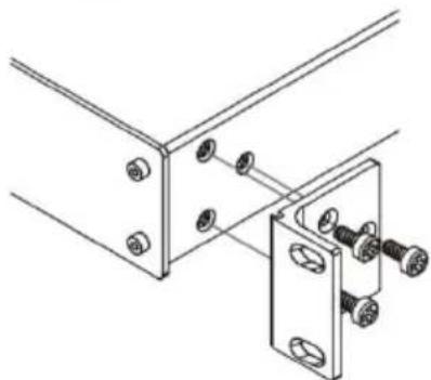
- Attach both ear brackets to the machine. To do so, remove the screws from each side of the machine (3 on each side), and replace those screws through the ear brackets.
natural_image
Technical line drawing of a mechanical bracket assembly with bolts and mounting holes (no text or symbols)- Place the ears of the machine against the rack rails, and insert the proper screws (not provided) through each of the four holes in the rack ears.
Note:
• In some models, the front panel may feature built-in rack ears
- Detachable rack ears can be removed for desktop use
• Always mount the machine in the rack before you attach any cables or connect the machine to the power
- If you are using a Kramer rack adapter kit (for a machine that is not 19"), see the Rack Adapters user manual for installation instructions available from our Web site
6 Connecting the VP-81KSi 8x1 UXGA/Audio STEP-IN Switcher
flowchart
graph TD
    A["Server"] -->|VGA Audio| B["SI-1 VGA"]
    A -->|VGA Audio| C["Computer Graphics Source"]
    A -->|VGA Audio| D["Computer Graphics Source"]
    A -->|VGA Audio| E["Power Amplifier with Speakers"]
    A -->|VGA Audio| F["Projector"]
    A -->|VGA Audio| G["To TP-122 or compatible receiver"]
    A -->|VGA Audio| H["To remote input selection switch"]
    A -->|VGA Audio| I["CAT 5"]
    A -->|VGA Audio| J["ETH"]
    A -->|VGA Audio| K["RS-232"]
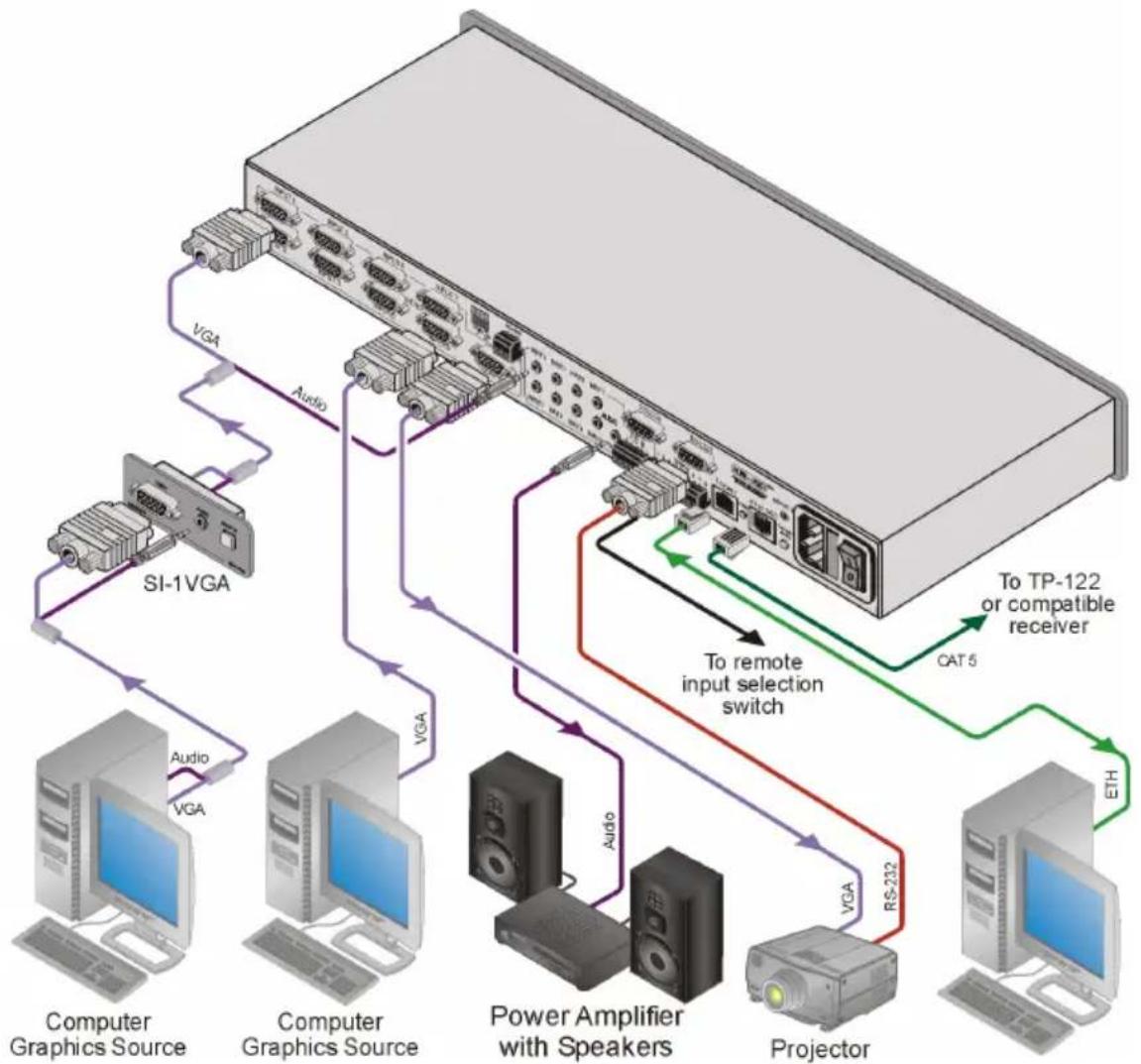
Figure 3: Connecting the VP-81KSi
To connect ^1 the VP-81KSi, as illustrated in the example in Figure 3:
-
Connect up to eight ^2 SI-1VGA Remote Step-in Panels to the VP-81KSi 15-pin HD VIDEO INPUT connectors ^3 and to the 3.5mm mini jacks (from 1 to 8).
-
Connect up to eight WUXGA computer graphics sources to the SI-1VGA 15-pin HD video connectors.
-
Connect up to eight unbalanced audio sources to the 3.5mm mini jack audio connectors on the SI-1VGA panels.
-
Connect the 15-pin HD VIDEO OUTPUT connector to a WUXGA acceptor (for example, a projector).
-
Connect the RJ-45 AV ON CAT 5 output connector to a compatible TP receiver (for example, TP-120).
- Connect the unbalanced audio 3.5mm AUDIO OUTPUT jack to an unbalanced audio acceptor (for example, power amplifier).
- Connect the balanced audio 5-pin terminal block (see Section 6.1) to an audio acceptor ^1 .
- Connect up to eight remote, contact closure input selection switches to the REMOTE terminal block (see Section 6.2).
- Connect a PC over a LAN to the Ethernet for remote operation.
-
Set the DIP-switches (see Section 6.6.1) for remote operation. You can connect a PC and/or controller to the:
■ RS-232 port (see Section 6.3)
■ RS-485 port (see Section 6.6.1) -
Connect ^1 the power cord ^2 .
6.1 Connecting the Balanced/Unbalanced Stereo Audio Output
This section illustrates how to wire the devices to the balanced audio output:
• A balanced stereo output connection, see Figure 4
• An unbalanced stereo output connection, see Figure 5
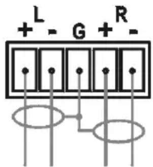
Figure 4: Balanced Stereo Audio Connection
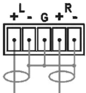
Figure 5: Unbalanced Stereo Audio Connection
6.2 Connecting Remote Contact Closure Input Selection Switches
You can connect remote input selection switches to the Remote terminal block on the rear panel of the VP-81KSi which enables you to remotely activate the relevant input.
The following example (see Figure 6) illustrates three switches (A, B and C) connected to remotely controlled inputs 1, 2 and 3 respectively (up to eight switches can be connected). Pressing switch A causes input 1 on the VP-81KSi to be the active input, pressing switch B causes input 2 to be the active input, and pressing switch C causes input 3 to be the active input.
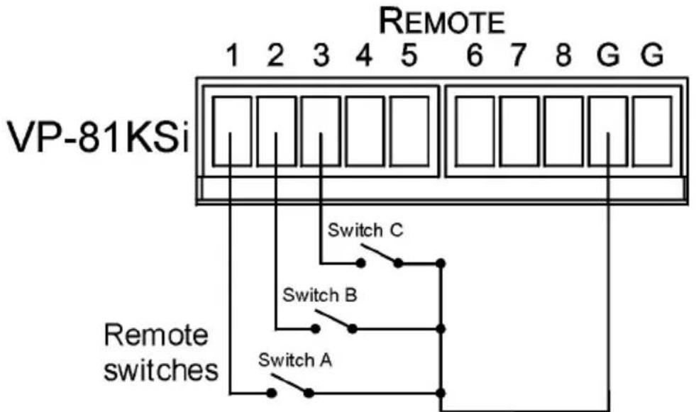
Figure 6: Remote Input Selection Switch Wiring
To connect remote input selection switches as illustrated in the example in Figure 6:
- Connect Switch A to pins 1 and G ^1 on the terminal block.
- Connect Switch B to pins 2 and G ^1 on the terminal block.
- Connect Switch C to pins 3 and G ^1 on the terminal block.
- If required, repeat for a total of up to eight switches.
6.3 Connecting the SI-1VGA Remote Step-in Module
For detailed instructions refer to the SI-1VGA Step-in Module Installation Instructions ^2 .
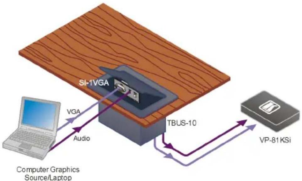
To connect an SI-1VGA remote step-in module to the VP-81KSi as illustrated in the example in Figure 7:
-
Mount the SI-1VGA in either the TBUS-10 or the K-POD301.
-
Using a 15-pin HD (male to male) cable ^1 , connect the 15-pin HD connector on the rear of the SI-1VGA to the corresponding input on the rear of the VP-81KSi.
- Using an audio cable with 3.5mm mini jacks at both ends ^2 , connect the 3.5mm mini connector on the rear of the SI-1VGA to the corresponding audio input on the rear of the VP-81KSi.
- Repeat steps 2 and 3 for each SI-1VGA remote step-in module.
flowchart
graph TD
    A["Computer Graphics Source/Laptop"] -->|VGA| B["SI-1VGA"]
    B -->|Audio| C["TBUS-10"]
    C -->|VGA| D["VP-81 KSi"]
    D -->|Audio| C
Figure 7: Connecting the SI-1VGA
6.4 Connecting the AV ON CAT 5 Twisted Pair Output
You can connect the VP-81KSi to any compatible Kramer TP (Twisted Pair) receiver, for example, TP-120 (no audio) or TP-122 (with audio).
For further details, refer to the relevant TP receiver user manual ^4 .
6.5 Connecting to the VP-81KSi via the RS-232 Port
You can connect to the VP-81KSi via an RS-232 connection using, for example, a PC.
To connect to the VP-81KSi via RS-232:
- Connect the RS-232 9-pin D-sub rear panel port on the VP-81KSi unit via a 9-wire straight cable (pin 2 to pin 2, pin 3 to pin 3, pin 5 to pin 5) to the RS-232 9-pin D-sub port on your PC
6.6 Connecting to the VP-81KSi via the RS-485 Port
You can operate the VP-81KSi via the RS-485 port from a distance of up to 1200m (3900ft) using any device equipped with an RS-485 port (for example, a PC). For successful communication, you must set the RS-485 machine number and bus termination.
To connect a device with a RS-485 port to the VP-81KSi:
- Connect the A (+) pin on the RS-485 port of the PC to the A (+) pin on the RS-485 port on the rear panel of the VP-81KSi
- Connect the B (−) pin on the RS-485 port of the PC to the B (−) pin on the RS-485 port on the rear panel of the VP-81KSi
- Connect the G pin on the RS-485 port of the PC to the G pin on the RS-485 port on the rear panel of the VP-81KSi
6.6.1 Setting the RS-485 Machine Number and Bus Termination DIP-switches
This section describes the VP-81KSi DIP-switch settings that determine the RS-485 machine number and bus termination.
Figure 8 illustrates the factory default DIP-switch positions.
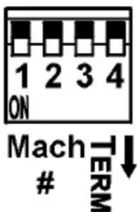
Figure 8: RS-485 DIP-switches
Table 3: RS-485 DIP-switch Settings
| DIP-switch Number | Function |
| 1, 2, 3 | Machine number (see Table 4)Default—All off (up), machine number 1 |
| 4 | RS-485 Bus TerminationDefault—Off (up) |
DIP-switches 1, 2 and 3 determine the RS-485 machine number of the
VP-81KSi. When several VP-81KSi units are connected, the machine number determines the unique identity of the VP-81KSi on the bus (see Table 4).
Note:
- When using a stand-alone VP-81KSi unit, set the machine number to 1 (factory default)
- When connecting more than one VP-81KSi, set the first machine (connected via RS-232) to be machine number 1. The other VP-81KSi units must each be set to a unique machine number between 2 and 16
Table 4: Machine Number DIP-switch Settings
| Machine Number | 1 | 2 | 3 |
| 1 (Default) | OFF | OFF | OFF |
| 2 | ON | OFF | OFF |
| 3 | OFF | ON | OFF |
| 4 | ON | ON | OFF |
| 5 | OFF | OFF | ON |
| 6 | ON | OFF | ON |
| 7 | OFF | ON | ON |
| 8 | ON | ON | ON |
DIP-switch 4 sets the RS-485 bus termination of the VP-81KSi. Only the first and last physical units on the RS-485 bus must be terminated, all others must be unterminated. Moving the DIP-switch up turns the termination off (default), moving the switch down turns the termination on.
6.6.2 Connecting and Controlling Multiple VP-81KSi Devices
You can daisy-chain up to eight VP-81KSi devices with operation via RS-232 from a PC or serial controller.
To daisy-chain up to eight VP-81KSi devices:
- Connect the RS-232 port ^1 on the first VP-81KSi device to the PC (see Section 6.3).
- Connect the RS-485 terminal block port on the first device to the RS-485 port on the second device, and so on for all devices.
- Set the DIP-switches (see Section 6.6.1) as follows:
■ The first device is machine number 1 and the following seven devices are machine numbers 2 to 8
- Terminate the first and last physical devices, that is, in this example terminate machine numbers 1 and 8. Ensure that all other devices are unterminated
6.7 Cascading Multiple VP-81KSi Devices
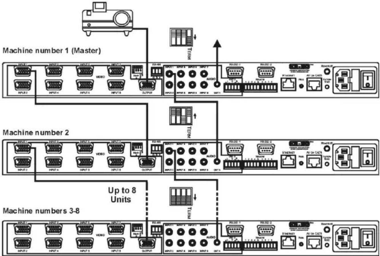
You can cascade up to eight VP-81KSi devices to build a single “virtual” switcher with up to 57 inputs and one output as illustrated in Figure 9.
To cascade up to eight VP-81KSi devices:
- Connect the output on the Master VP-81KSi to the video acceptor (for example, a projector).
- Connect Input 1 on the Master VP-81KSi to the output of the second device.
- Connect Input 1 on the second VP-81KSi to the output of the third device, and so on for all devices.
Note: Audio connections must follow the same connection scheme as the video connections.
- Set the DIP-switches (see Section 6.6.1) as follows:
■ The first device is machine number 1 (Master) and the following seven devices are machine numbers 2 to 8
■ Terminate the first and last physical devices, that is, terminate machine numbers 1 and 8. Ensure that all other devices are unterminated
flowchart
graph TD
    A["Machine number 1 (Master)"] --> B["RS-488"]
    B --> C["INPUT1 INPUT2 INPUT3 INPUT4 INPUT5 INPUT6 INPUT7 INPUT8 INPUT9 INPUT10 INPUT11 INPUT12 INPUT13 INPUT14 INPUT15 INPUT16 INPUT17 INPUT18 INPUT19 INPUT20 INPUT21 INPUT22 INPUT23 INPUT24 INPUT25 INPUT26 INPUT27 INPUT28 INPUT29 INPUT30 INPUT31 INPUT32 INPUT33 INPUT34 INPUT35 INPUT36 INPUT37 INPUT38 INPUT39 INPUT40"]
    C --> D["OUTPUT"]
    D --> E["RS-292-1"]
    E --> F["INPUT 1.0"]
    E --> G["INPUT 2.0"]
    E --> H["INPUT 3.0"]
    E --> I["INPUT 4.0"]
    E --> J["INPUT 5.0"]
    E --> K["INPUT 6.0"]
    E --> L["INPUT 7.0"]
    E --> M["INPUT 8.0"]
    E --> N["INPUT 9.0"]
    E --> O["INPUT 10.0"]
    E --> P["INPUT 11.0"]
    E --> Q["INPUT 12.0"]
    E --> R["INPUT 13.0"]
    E --> S["INPUT 14.0"]
    E --> T["INPUT 15.0"]
    E --> U["INPUT 16.0"]
    E --> V["INPUT 17.0"]
    E --> W["INPUT 18.0"]
    E --> X["INPUT 19.0"]
    E --> Y["INPUT 20.0"]
    E --> Z["INPUT 21.0"]
    E --> AA["INPUT 22.0"]
    E --> AB["INPUT 23.0"]
    E --> AC["INPUT 24.0"]
    E --> AD["INPUT 25.0"]
    E --> AE["INPUT 26.0"]
    E --> AF["INPUT 27.0"]
    E --> AG["INPUT 28.0"]
    E --> AH["INPUT 29.0"]
    E --> AI["INPUT 30.0"]
    E --> AJ["INPUT 31.0"]
    E --> AK["INPUT 32.0"]
    E --> AL["INPUT 33.0"]
    E --> AM["INPUT 34.0"]
    E --> AN["INPUT 35.0"]
    E --> AO["INPUT 36.0"]
    E --> AP["INPUT 37.0"]
    E --> AQ["INPUT 38.0"]
    E --> AR["INPUT 39.0"]
    E --> AS["INPUT 40.0"]
    E --> AT["INPUT 41.0"]
    E --> AU["INPUT 42.0"]
    E --> AV["INPUT 43.0"]
    E --> AW["INPUT 44.0"]
    E --> AX["INPUT 45.0"]
    E --> AY["INPUT 46.0"]
    E --> AZ["INPUT 47.0"]
    E --> BA["INPUT 48.0"]
    E --> BB["INPUT 49.0"]
    E --> BC["INPUT 50.0"]
    E --> BD["INPUT 51.0"]
    E --> BE["INPUT 52.0"]
    E --> BF["INPUT 53.0"]
    E --> BG["INPUT 54.0"]
    E --> BH["INPUT 55.0"]
    E --> BI["INPUT 56.0"]
    E --> BJ["INPUT 57.0"]
    E --> BK["INPUT 58.0"]
    E --> BL["INPUT 59.0"]
    E --> BM["INPUT 60.0"]
    E --> BN["INPUT 61.0"]
    E --> BO["INPUT 62.0"]
    E --> BP["INPUT 63.0"]
    E --> BQ["INPUT 64.0"]
    E --> BR["INPUT 65.0"]
    E --> BS["INPUT 66.0"]
    E --> BT["INPUT 67.0"]
    E --> BU["INPUT 68.0"]
    E --> BV["INPUT 69.0"]
    E --> BW["INPUT 70.0"]
    E --> BX["INPUT 71.0"]
    E --> BY["INPUT 72.0"]
    E --> BZ["INPUT 73.0"]
    E --> CA["INPUT 74.0"]
    E --> CB["INPUT 75.0"]
    E --> CC["INPUT 76.0"]
    E --> CD["INPUT 77.0"]
    E --> CE["INPUT 78.0"]
    E --> CF["INPUT 79.0"]
    E --> CG["INPUT 80.0"]
    E --> CH["INPUT 81.0"]
    E --> CI["INPUT 82.0"]
    E --> CJ["INPUT 83.0"]
    E --> CK["INPUT 84.0"]
    E --> CL["INPUT 85.0"]
    E --> CM["INPUT 86.0"]
    E --> CN["INPUT 87.0"]
    E --> CO["INPUT 88.0"]
    E --> CP["INPUT 89.0"]
    E --> CQ["INPUT 90.0"]
    E --> CR["INPUT 91.0"]
    E --> CS["INPUT 92.0"]
    E --> CT["INPUT 93.0"]
    E --> CU["INPUT 94.0"]
    E --> CV["INPUT 95.0"]
    E --> CW["INPUT 96.0"]
    E --> CX["INPUT 97.0"]
    E --> CY["INPUT 98.0"]
    E --> CZ["INPUT 99.0"]
Figure 9: Cascading up to Eight VP-81KSi Devices
Note: The video acceptor must be connected to the Master output. The outputs of all other devices may be connected to any input on the subsequent device.
For operation of cascaded VP-81KSi devices, see Section 7.4.
6.8 Controlling a Remote RS-232 Device
Use the Kramer K-Config software ^1 to define macros sent from the RS-232-2 port to remote RS-232 serial devices (for example, a projector). For instructions on using the K-Config software, see the K-Config software guide.
A computer running the K-Config software can be connected to the VP-81KSi via either the RS-232-1 serial or the Ethernet ports.
You can configure RS-232-2 port command macros to send any data on one of the two possible triggers:
- The “Device startup” trigger. This trigger is generated when one or more signals are detected on any of the inputs and can be used for example, to activate a projector connected to the output of the VP-81KSi
- The “Device inactivity” trigger. This trigger is generated when there is no signal detected on any input during the inactivity timeout period (which is set using the K-Config software to be between 0 and 180 minutes). This trigger can be used for example, to deactivate a projector connected to the output of the VP-81KSi
6.9 Connecting to the VP-81KSi via the Ethernet Port
You can connect the VP-81KSi via the Ethernet in the following ways:
- For direct connection to the PC, use a crossover cable (see Section 6.9.1)
- For connection via a network hub or network router, use a straight through cable (see Section 6.9.2)
Note: The following instructions are valid only if your PC uses a fixed IP address. If your PC receives an IP address from a DHCP server, consult your IT department regarding a suitable IP address.
6.9.1 Connecting Directly to the Ethernet Port
You can connect the Ethernet port of the VP-81KSi to the Ethernet port on your PC via a crossover cable with RJ-45 connectors.
This type of connection is recommended for identification of the factory default IP address of the VP-81KSi during the initial configuration
To connect the VP-81KSi directly to a PC:
- Using a crossover cable, connect the VP-81KSi to the PC via the Ethernet port on both units.
- On the PC, click Start > Control Panel.
- Double-click Network Connections.
- Right-click, and from the menu select Properties. The Local Area Connection Properties window appears.
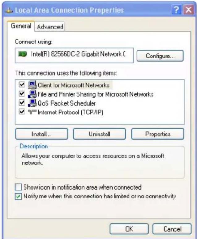
Figure 10: Local Area Connection Properties Window
- Select Internet Protocol (TCP/IP) (see Figure 10).
- Click the Properties button.
- Select Use the following IP address, and fill in the details as shown in Figure 11.
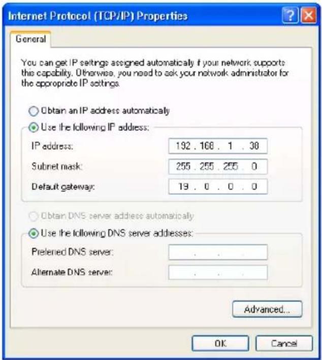
Figure 11: Internet Protocol (TCP/IP) Properties Window
- Click OK.
6.9.2 Connecting via a Network Hub, Switch, or Router
You can connect the Ethernet port of the VP-81KSi to the Ethernet port on a network hub, switch, or router, via a straight through cable with RJ-45 connectors. The VP-81KSi Ethernet port has to be configured to be compatible with your network (see Section 6.9.3).
6.9.3 Configuring the Ethernet Port on the VP-81KSi
To configure the Ethernet port on the VP-81KSi, download the P3K Ethernet Configuration software ^1 to your PC, extract the files to a folder, and install the software.
To configure the VP-81KSi Ethernet port:
-
Click Start > All Programs > Kramer > P3K Wizard The P3K Wizard window appears.
-
Click Connect. The Connect window appears.
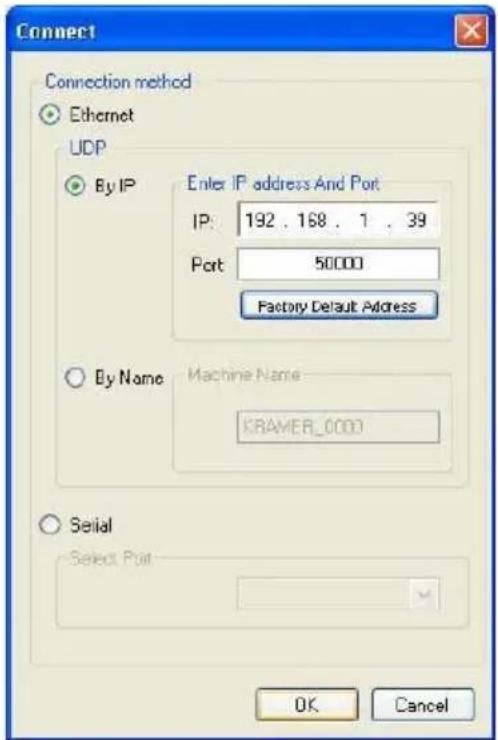
Figure 12: Connect Window
-
Select one of the following methods to connect to the Ethernet port of the VP-81KSi:
-
Ethernet, if you are connected via an Ethernet cable. Enter the IP address ^1 or the machine name
The default IP address is 192.168.1.39 and the default name for the unit is KRAMER XXXX^2 - Serial, if you are connected via a serial port. Select the COM port from the Select Port drop-down list.
4. Click OK.
The Device Properties window appears.
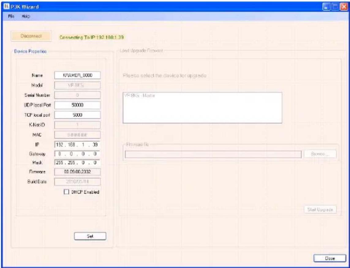
Figure 13: Device Properties Window
- Make the required changes.
- Click Set to save changes, or click Close to exit and not save the changes.
7 Operating the VP-81KSi Locally via the Front Panel Buttons
Powering up the VP-81KSi recalls the previous settings (that is, the state of the unit when it was powered down) from the non-volatile memory.
7.1 Using the Front Panel INPUT SELECTOR Buttons
Table 5 describes the input selector button illumination descriptions.
Table 5: Button Illumination Descriptions
| Button Color | Selected | Input Signal |
| Red | Yes | No |
| Green | No | Yes |
| Violet | Yes | Yes |
| Button does not light | No | Yes or no |
To switch an input to the outputs, press one of the eight front panel INPUT SELECTOR buttons. The INPUT SELECTOR button lights (see Table 5) and switches the input simultaneously to both the VGA and AV ON CAT 5 TP outputs.
7.2 Using the Audio-Follow-Video/Breakaway Modes
By default, the VP-81KSi switches in AFV (Audio-Follow-Video) mode in which all operations relate to both the video and audio. When in this mode, both the VIDEO and the AUDIO buttons are lit.
7.2.1 Operating in Breakaway Mode
To operate in breakaway mode in which video and audio channels switch independently:
- Press either the VIDEO button or the AUDIO button.
If the VIDEO button lights, the switching relates just to video (and the audio remains unchanged)
If the AUDIO button lights, the switching relates only to audio (and the video remains unchanged)
7.2.2 Switching to Audio Follow Video Mode
To switch to AFV (Audio Follow Video) mode:
- Press the VIDEO and the AUDIO buttons simultaneously
7.3 Setting the Audio Output Gain
You can set the audio output gain using the AUDIO GAIN + and - buttons.
To set the audio output gain:
- Press an input button.
The input button lights.
- Press either the AUDIO GAIN + (to increase) or AUDIO GAIN - (to decrease) button to vary the gain.
7.4 Operating Cascaded VP-81KSi Devices
Selecting an input on a device selects the required input and automatically selects the interconnected input on the subsequent device.
Given the example illustrated in Figure 9, pressing Input 4 on device 2, selects Input 4 on device 2 and automatically selects Input 1 on the Master device.
Pressing Input 5 button on device 8 selects Input 5 on device 8 and automatically selects Input 1 on all subsequent devices.
8 Operating the VP-81KSi Remotely
You can operate the VP-81KSi remotely using the Kramer K-Single Control Software on a PC. For full details, see the Kramer Control Software Online Guide.
The VP-81KSi can be operated remotely via any of the following methods:
• The Kramer RC-IR3 Infra-Red Remote Control transmitter
- Contact closure switches (for connecting, see Section 6.2)
• SI-1VGA Remote Step-in Panel (for connecting, see Section 6.3)
• RS-232 (for connecting, see Section 6.4)
• RS-485 (for connecting, see Section 6.6)
- Ethernet over a LAN using a Web browser (see Section 9)
9 Operating the VP-81KSi Remotely using a Web Browser
The embedded Web pages can be used to remotely operate the VP-81KSi using a Web browser and an Ethernet connection.
Before attempting to connect:
• Perform the procedures in Section 6.9.
- Ensure that the Java™ software is installed and functioning correctly on your computer. If not, download it from www.java.com
- Ensure that your browser is supported—Microsoft IE (V6.0 and higher), Google Chrome, Firefox (V3.0 and higher).
To check that Java is installed and running correctly, browse to http://www.java.com/en/download/help/testvm.xml
This page runs a test and displays a Java success (see Figure 14) or failure message.
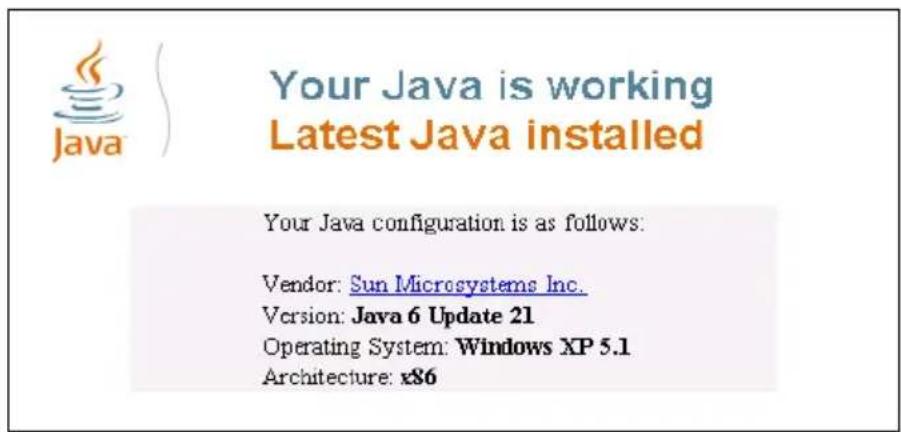
Figure 14: Java Test Page Success Message
If you do not see the success message, follow the instructions on the page to:
- Load and enable Java
- Enable Javascript in your browser
9.1 To Log On to the VP-81KSi Web Pages
To log on to VP-81KSi Web pages:
- Open your Internet browser.
- Type the unit's IP number (see Table 7) in the Address bar of your browser.
http://192.168.1.39
The Loading page appears.
Kramer Electronics Web K-Router
?
Loading...
To view this page you must:
• Install JAVA.
- Enable JAVA in your browser
- Enable JavaScript in your browser.
© 2009 www.kramerelectronics.com
Figure 15: The Loading Page
The first time that you run the program, the Warning-Security screen appears.
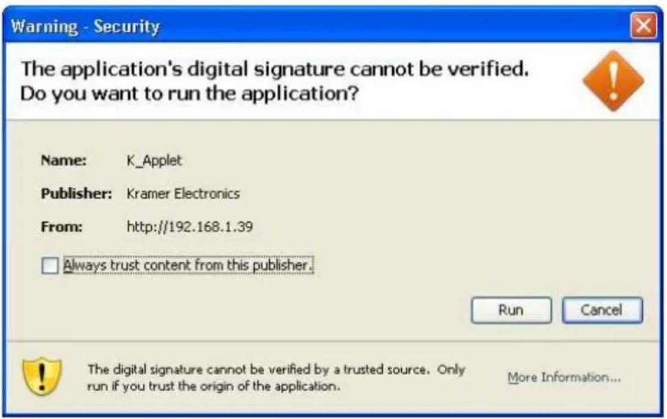
Figure 16: First Time Security Warning
3. Click Run.
The main switching control Home page is displayed which shows a graphical interpretation of the front panel (see Figure 17).
The Web pages let you control the VP-8x8AK via the Ethernet. The menu appears on the left side of the screen. There are three remote operation Web pages:
• The switching matrix (see Section 9.2)
• Audio gain control (See Section 9.3)
- Configuration (See Section 9.4)
A description of each Web page is displayed if you hover your mouse over the question mark that appears on the left side of the screen.
9.2 The Switching Matrix Page
The VP-81KSi switching matrix page lets you route any or all of the eight inputs to the output by clicking the audio and/or video signal indicators (purple and blue, respectively).
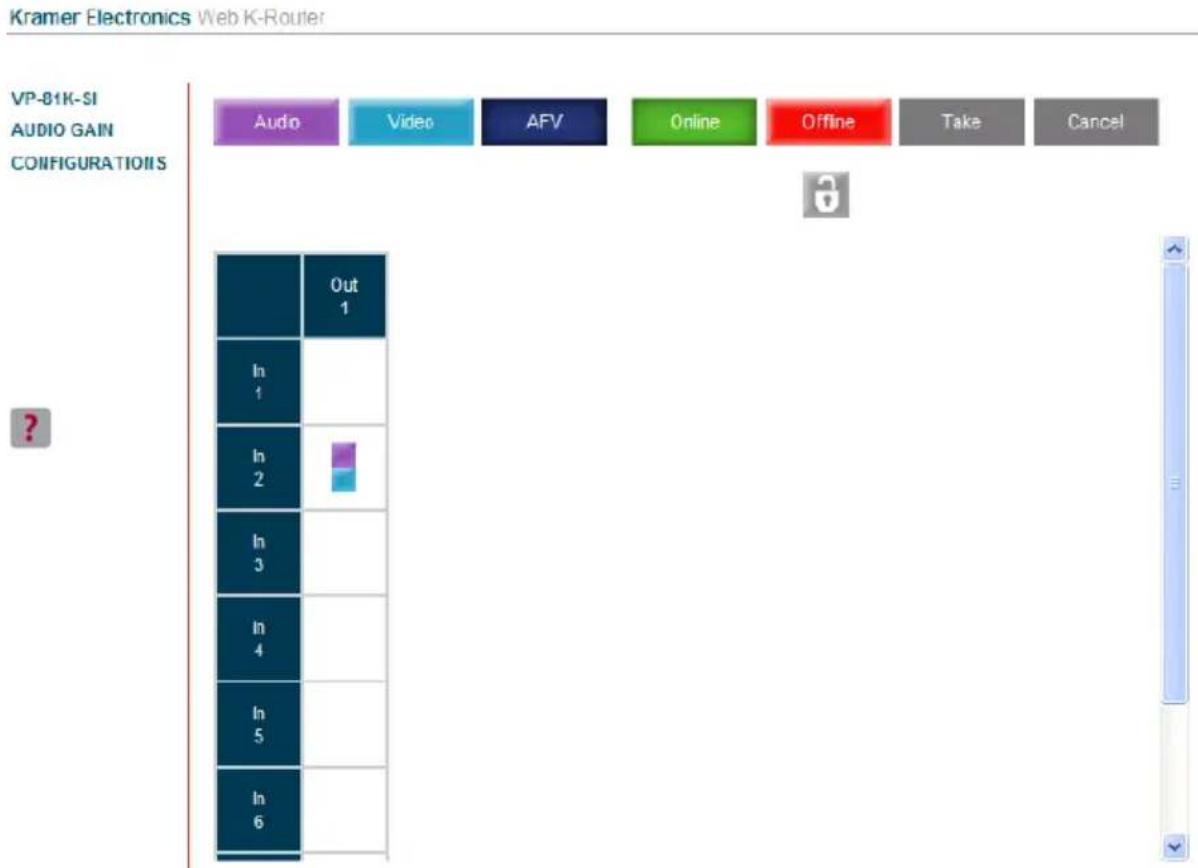
Figure 17: VP-81KSi Switching Matrix Page
You can perform the following operations via this Web page:
- Operate in the AFV mode or switch the audio and video separately, by clicking the Audio, Video or AFV buttons (see Section 9.2.1)
- Select an audio and/or video signal ^1 by clicking that signal indicator
• Operate in the At Once or Confirm mode (see Section 9.2.2) - Click the lock icon to lock or unlock the front panel
9.2.1 Switching an Input to an Output
To switch an input to an output (for example, input 4 to output 1):
- Click on the dark blue AFV mode button. (To switch only the video or audio channel, click on purple Audio or blue Video button respectively.) The border of the button turns dark.
- Click on the switching point within the matrix (In 4 to Out 1). The audio/video signal indicators move to the In 4 to Out 1 switching matrix box, indicating that In 4 is now switched to Out 1.
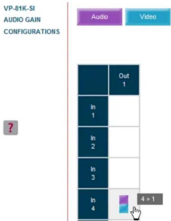
Figure 18: Switching an Input to an Output
9.2.2 Operating in the Confirm Mode
By default, the device is set to the At-Once mode.
To operate in the Confirm mode:
- Click the red Offline button.
The border of the button turns dark.
- Click the desired switching-point in the switching matrix.
Audio/video indicator outlines appear on the matrix and the Take and Cancel buttons turn blue.
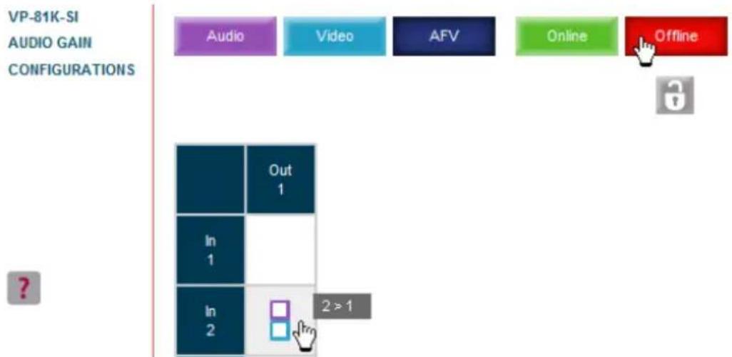
Figure 19: Switching an Input to an Output
-
Click either Take to accept the changes or Cancel to abandon them.
-
Click the Online button to exit the Confirm mode.
If you click the Online button before you click the TAKE button, the following warning shown in Figure 20 appears.
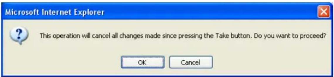
Figure 20: Exiting Offline Warning
Clicking OK cancels all changes made. Clicking Cancel returns you to the switching matrix screen with the changes made but not saved.
9.3 The Audio Gain Page
The Audio Gain screen lets you set the gain for each of the input and the output channels.
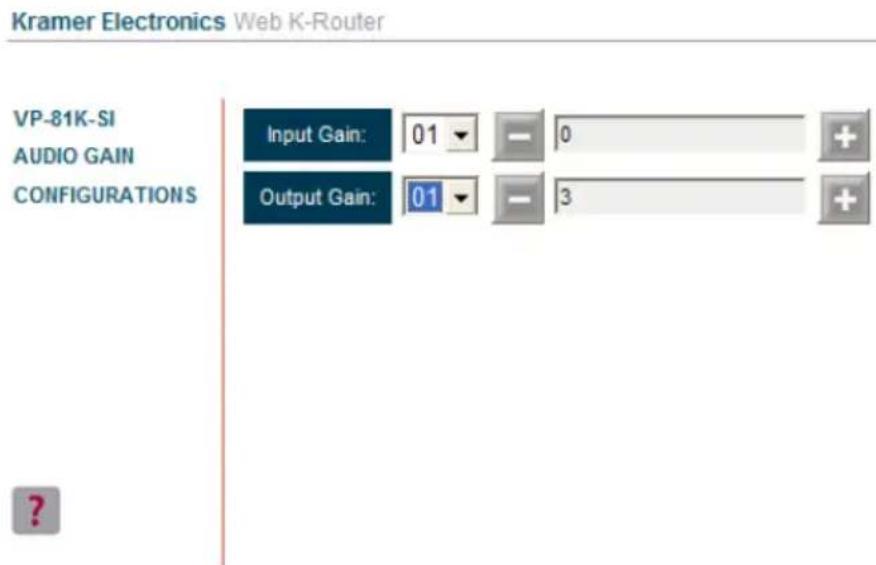
Figure 21: Audio Gain Page
To change an input or output gain:
- Using the Input Gain or Output Gain drop-down list, select the channel number.
- Click and hold the + or - button to increase or decrease the gain respectively. Each click on the + or - button increases/decreases the audio gain by 0.5 units.
9.4 The Configurations Page
The Configurations page lets you view some Ethernet settings and change others (see Figure 22). Fields with a white background are editable; fields with a blue background are read-only.
To change the configuration definitions:
- Click CONFIGURATIONS.
The Configurations Web page appears.
- Modify the values as required.
- Click the blue Submit button to apply changes or Cancel to abandon them. A confirmation window appears asking if you are sure you want to change the network settings.
- Click Yes.
A window appears informing you that the configuration has been successfully changed.
- Click OK
- If the IP address has been changed, close your browser and reload the Web page using the new IP address.
Kramer Electronics Web K-Router
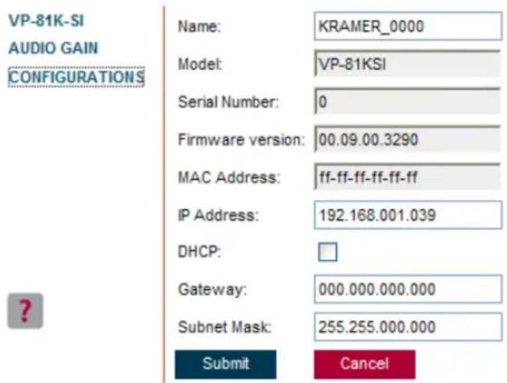
Figure 22: Configurations Page
10 Upgrading the Firmware
For instructions on upgrading the firmware, see the document Updating the VP-81KSi Firmware Using P3K Software.
The latest version of firmware and installation instructions can be downloaded from the Kramer Web site at www.kramerelectronics.com.
11 EDID
Each input on the VP-81KSi has a factory default EDID loaded (see Section 14). The EDID for each input can be changed independently by uploading an EDID binary file to each input via the RS-232 port using Kramer EDID Designer ^1 .
12 Technical Specifications
Table 6 lists the technical specifications ^1 of the VP-81KSi.
Table 6: Technical Specifications of the VP-81KSi
| INPUTS: | 8 XGA on 15-pin HD (F) connectors8 Unbalanced stereo audio on 3.5mm mini jacks | |
| OUTPUTS: | 1 XGA on 15-pin HD connector1 TP on RJ-45 connector1 unbalanced stereo audio on a 3.5mm mini jack1 balanced audio stereo on a 5-pin detachable terminal block | |
| MAX. OUTPUT LEVEL: | VIDEO: 2Vpp | AUDIO: Stereo Unbalanced 7.8VppStereo Balanced 15.6Vpp differential (17dBu) |
| BANDWIDTH (-3dB): | VIDEO: Out 440MHzCAT 5 (Rec Out) 150MHz | AUDIO: Stereo Unbalanced 20kHzStereo Balanced 20kHz |
| RESOLUTION: | VIDEO: VGA up to WUXGA | |
| DIFF. GAIN: | VIDEO: XGA 0.04% | |
| DIFF. PHASE: | VIDEO: UXGA: 0.07Deg | |
| K FACTOR: | VIDEO: UXGA 0.2% | |
| S/N RATIO: | VIDEO: UXGA 68.3dB to 5MHz | AUDIO: Stereo Unbalanced 74dB @1kHzStereo Balanced 74.4dB @1kHzCAT5 (Rec Out) 69.8dB |
| CROSSTALK (all hostile): | VIDEO: UXGA -52dB to 5MHz | AUDIO: Local Stereo Unbalanced -73dB @1kHzLocal Stereo Balanced <72dB @1kHz |
| VOLUME CONTROL: | AUDIO: Stereo Unbalanced -65.4 to 25.8dBStereo Balanced -59.4 to 31.8dB | |
| COUPLING: | VIDEO: UXGA—DCTP Out—DC | AUDIO: Stereo Unbalanced—In AC, Out DCStereo Balanced—In AC, Out DC |
| AUDIO THD + NOISE: | Stereo Unbalanced 0.08%Stereo Balanced 0.08% | |
| AUDIO 2nd HARMONIC: | Stereo Unbalanced 0.001%Stereo Balanced 0.001% | |
| POWER SOURCE: | 100-240V AC 50/60Hz 29VA | |
| DIMENSIONS: | 43.6cm x 19.1cm x 4.4cm (19" x 7.5" x 1U) W, D, H rack-mountable | |
| WEIGHT: | 1.7kg (3.8lbs) approx. | |
| ACCESSORIES: | Power cord, Windows®-based Kramer control software, RC-IR3 Infrared Remote Control transmitter, one SI-1VGA Remote Step-in module | |
| OPTIONS: | External remote IR receiver cable ^2 15m extension cable ^3 SI-1VGA Remote Step-in Module | |
13 Communication Parameters
Table 7 lists the communication parameters as used in Kramer Electronics products.
Table 7: Communication Parameters
| RS-232 | ||||
| Protocol 2000 | Protocol 3000 (Default) | |||
| Baud Rate: | 9600 | Baud Rate: | 115,200 | |
| Data Bits: | 8 | Data Bits: | 8 | |
| Stop Bits: | 1 | Stop Bits: | 1 | |
| Parity: | None | Parity: | None | |
| Command Format: | HEX | Command Format: | ASCII | |
| Example (Output 1 to Input 1): | 0x01, 0x81, 0x81, 0x81 | Example (Output 1 to Input 1): | #AV 1>1 | |
| Switching Protocol | ||||
| P2000 -> P3000 | P3000 -> P2000 | |||
| Command: | 0x38, 0x80, 0x83, 0x81 | Command: | #P2000 | |
| Front Panel: | Press and hold Output 1 and Output simultaneously | Front Panel: | Press and hold Output 1 and Output 2 simultaneously | |
| Ethernet Factory Default Values | ||||
| IP Address: 192.168.1.39Mask: 255.255.255.0Gateway: 192.168.1.1 | Power cycle the unit while pressing the Factory Reset button, located on the rear panel of the unit. | |||
| TCP Port #: 5000 | ||||
| UDP Port #: 50000 | ||||
14 Default EDID
The default EDID is stored in all inputs.
Monitor
Model name..... VP-81K-SI
Manufacturer..... KRM
Plug and Play ID...... KRM0808
Serial number...... 2
Manufacture date...... 2009, ISO week 10
EDID revision...... 1.3
Input signal type..... Analog 0.700,0.000 (0.7V p-p)
Sync input support..... Separate, Composite, Sync-on-green
Display type...... RGB color
Screen size...... 360 x 290 mm (18.2 in)
Power management...... Standby, Suspend, Active off/sleep
Extension blocs...... None
DDC/CI...... Not supported
Color characteristics
Default color space..... sRGB
Display gamma...... 2.00
Red chromaticity...... Rx 0.611 - Ry 0.329
Green chromaticity...... Gx 0.312 - Gy 0.559
Blue chromaticity...... Bx 0.148 - By 0.131
White point (default).... Wx 0.320 - Wy 0.336
Additional descriptors... None
Timing characteristics
Range limits...... Not available
GTF standard...... Not supported
Additional descriptors... None
Preferred timing..... Yes
Native/preferred timing.. 1024x768p at 60Hz (4:3)
Modeline...... "1024x768" 65.000 1024 1048 1184 1344 768 771 777 806 -hsync -vsync
Detailed timing #1..... 1280x800p at 60Hz (1:1)
Modeline..... "1280x800" 71.000 1280 1328 1360 1440 800 803 809 823 +hsync -vsync
Standard timings supported
640 x 480p at 60Hz - IBM VGA
640 x 480p at 67Hz - Apple Mac II
640 x 480p at 72Hz - VESA
640 x 480p at 75Hz - VESA
800 x 600p at 56Hz - VESA
800 x 600p at 60Hz - VESA
800 x 600p at 72Hz - VESA
800 x 600p at 75Hz - VESA
1024 x 768p at 60Hz - VESA
1024 x 768p at 70Hz - VESA
1024 x 768p at 75Hz - VESA
1280 x 1024p at 75Hz - VESA
1280 x 1024p at 60Hz - VESA STD
1280 x 960p at 60Hz - VESA STD
1400 x 1050p at 60Hz - VESA STD
1440 x 900p at 60Hz - VESA STD
1600 x 1200p at 60Hz - VESA STD
1920 x 1200p at 60Hz - VESA STD
1920 x 1080p at 60Hz - VESA STD
Report information
Date generated...... 12/7/2010
Software revision...... 2.43.0.822
Operating system...... 5.1.2600.2.Service Pack 3
Raw data
00,FF,FF,FF,FF,FF,FF,00,2E,4D,08,08,02,00,00,00,0A,13,01,03,6E,24,1D,64,EE,9C,20,9C,54,4F,8F,26,21,52,56,3F,CF,00,81,80,81,40,90,40,95,00,A9,40,D1,00,D1,C0,01,01,64,19,00,40,41,00,26,30,18,88,36,00,30,E4,10,00,00,18,BC,1B,00,A0,50,20,17,30,30,20,36,00,20,20,00,00,00,1A,00,00,00,FC,00,56,50,2D,38,31,4B,2D,53,49,0A,20,20,20,00,00,00,10,00,56,50,2D,38,31,4B,2D,53,49,20,0A,20,20,00,68
15 Table of ASCII Codes for Serial Communication (Protocol 3000)
Table 8 lists the ASCII values to switch an input to an output for a single VP-81KSi device. For more detailed information, see Protocol 3000 Section 17.2.
Table 8: VP-81KSi Video and Audio Signal Codes
| Video | Audio | |
| IN 1 | #V 1>1 | #A 1>1 |
| IN 2 | #V 2>1 | #A 2>1 |
| IN 3 | #V 3>1 | #A 3>1 |
| IN 4 | #V 4>1 | #A 4>1 |
| IN 5 | #V 5>1 | #A 5>1 |
| IN 6 | #V 6>1 | #A 6>1 |
| IN 7 | #V 7>1 | #A 7>1 |
| IN 8 | #V 8>1 | #A 8>1 |
Table 9 lists the codes that set the audio input gain. For more detailed information, see Section 17.2.
Table 9: VP-81KSi Audio Input Gain Codes
| INPUT 1 | INPUT 5 | INPUT X* | Level [Rel] | ||
| #AUD-LVL 1,1, -63CR | ... | #AUD-LVL 1,5, -63CR | ... | #AUD-LVL 1,X, -63CR | -63dB Mute |
| ⋮ | ⋮ | ⋮ | |||
| #AUD-LVL 1,1, -50CR | ... | #AUD-LVL 1,5, -50CR | ... | #AUD-LVL 1,X, -50CR | -50dB |
| ⋮ | ⋮ | ⋮ | |||
| #AUD-LVL 1,1, 0CR | ... | #AUD-LVL 1,5, 0CR | ... | #AUD-LVL 1,X, 0CR | 0dB |
| ⋮ | ⋮ | ⋮ | |||
| #AUD-LVL 1,1, 7CR | ... | #AUD-LVL 1,5, 7CR | ... | #AUD-LVL 1,X, 7CR | +7dB (Max) |
* Where X is the input number from 1 - 8. For example, for channel 7 and relative level -50dB, #AUD-LVL 1,7, -50CR
Table 10 lists the codes that set the video and audio output gain. For more detailed information, see Section 17.1.2.
Table 10: VP-81KSi Audio and Audio Output Gain Codes
| OUTPUT 1 | Level [Rel] |
| #AUD-LVL 2,1, -30CR | -30dB |
| ⋮ | |
| #AUD-LVL 2,1, 0CR | 0dB |
| ⋮ | |
| #AUD-LVL 2,1, 20CR | +20dB |
16 Table of Hex Codes for Serial Communication (Protocol 2000)
Table 11 lists the Hex values to switch an input to an output for a single VP-81KSi machine. For more detailed information, see Protocol 2000 ^1 (see Section 17.3).
Table 11: VP-81KSi Hex Codes for Protocol 2000
| Video | Audio | |
| IN 1 | 01, 81, 81, 81 | 02, 81, 81, 81 |
| IN 2 | 01, 82, 81, 81 | 02, 82, 81, 81 |
| IN 3 | 01, 83, 81, 81 | 02, 83, 81, 81 |
| IN 4 | 01, 84, 81, 81 | 02, 84, 81, 81 |
| IN 5 | 01, 85, 81, 81 | 02, 85, 81, 81 |
| IN 6 | 01, 86, 81, 81 | 02, 86, 81, 81 |
| IN 7 | 01, 87, 81, 81 | 02, 87, 81, 81 |
| IN 8 | 01, 88, 81, 81 | 02, 88, 81, 81 |
Table 12 lists the Hex codes that increase or decrease audio input gain.
Table 12: VP-81KSi Hex Codes that Increase/Decrease Audio Input Gain
| IN 1 | IN 2 | IN 3 | IN 4 | IN 5 | IN 6 | IN 7 | IN 8 | |
| Increase | 18 81 86 81 | 18 82 86 81 | 18 83 86 81 | 18 84 86 81 | 18 85 86 81 | 18 86 86 81 | 18 87 86 81 | 18 88 86 81 |
| Decrease | 18 81 87 81 | 18 82 87 81 | 18 83 87 81 | 18 84 87 81 | 18 85 87 81 | 18 86 87 81 | 18 87 87 81 | 18 88 87 81 |
Table 13 lists the Hex codes that set the audio input gain.
Note: Before sending any of the codes in Table 13, the command 2A 86 80 81 must be sent.
Table 13: Hex Codes that Set the Audio Input Gain
| IN 1 | IN 2 | IN 3 | IN 4 | IN 5 | IN 6 | IN 7 | IN 8 | Level [Rel] |
| 16 81 80* 81 | 16 82 80* 81 | 16 83 80* 81 | 16 84 80* 81 | 16 85 80* 81 | 16 86 80* 81 | 16 87 80* 81 | 16 88 80* 81 | -63dB Mute |
| ⋮ | ⋮ | ⋮ | ⋮ | ⋮ | ⋮ | ⋮ | ⋮ | |
| 16 81 8D* 81 | 16 82 8D* 81 | 16 83 8D* 81 | 16 84 8D* 81 | 16 85 8D* 81 | 16 86 8D* 81 | 16 87 8D* 81 | 16 88 8D* 81 | -50dB |
| ⋮ | ⋮ | ⋮ | ⋮ | ⋮ | ⋮ | ⋮ | ⋮ | |
| 16 81 BF* 81 | 16 82 BF* 81 | 16 83 BF* 81 | 16 84 BF* 81 | 16 85 BF* 81 | 16 86 BF* 81 | 16 87 BF* 81 | 16 88 BF* 81 | 0dB |
| ⋮ | ⋮ | ⋮ | ⋮ | ⋮ | ⋮ | ⋮ | ⋮ | |
| 16 81 C6* 81 | 16 82 C6* 81 | 16 83 C6* 81 | 16 84 C6* 81 | 16 85 C6* 81 | 16 86 C6* 81 | 16 87 C6* 81 | 16 88 C6* 81 | +7dB (Max) |
* BYTE 3 = 0x80 + Gain Value (0x00-0x46)
Table 14 lists the Hex codes that increase or decrease the audio output gain.
Table 14: VP-8x8AK Hex Codes for Increasing/Decreasing the Output Gain
| OUT 1 | OUT 2 | OUT 3 | OUT 4 | OUT 5 | OUT 6 | OUT 7 | OUT 8 | |
| Increase | 18 81 80 81 | 18 82 80 81 | 18 83 80 81 | 18 84 80 81 | 18 85 80 81 | 18 86 80 81 | 18 87 80 81 | 18 88 80 81 |
| Decrease | 18 81 81 81 | 18 82 81 81 | 18 83 81 81 | 18 84 81 81 | 18 85 81 81 | 18 86 81 81 | 18 87 81 81 | 18 88 81 81 |
Table 15 lists the Hex codes that set the audio output gain.
Before sending the any of the codes in Table 15, the command 2A 87 80 81 must be sent.
Table 15: Hex Codes for Setting the Audio Output Gain
| OUT 1 | Level [Rel] |
| 16 81 80* 81 | -30dB |
| ⋮ | |
| 16 81 9E* 81 | 0dB |
| ⋮ | |
| 16 81 B2* 81 | +20dB |
*BYTE 3 = 0x80 + Gain Value (0x00-0x32)
17 Kramer Protocol
Section 17.1 describes how to switch between Protocol 3000 and Protocol ^1 2000. By default, the VP-81KSi is set to protocol 3000 (see Section 17.2) but is also compatible with Kramer's Protocol 2000 (see Section 17.3).
17.1 Switching Protocols
You can switch protocols either via the front panel buttons (see Section 17.1.1) or the protocol commands (see Section 17.1.2).
17.1.1 Switching Protocols via the Front Panel Buttons
To switch from protocol 3000 to protocol 2000 via the:
- Front panel buttons, press the IN 1 and IN 2 button simultaneously
- Infrared remote control transmitter, press the TAKE button and then 13
To switch from protocol 2000 to protocol 3000 via the: - Front panel buttons, press the IN 1 and IN 3 button simultaneously
- Infrared remote control transmitter, press the TAKE button and then 16
17.1.2 Switching Protocols via Protocol Commands
To switch from protocol 3000 to protocol 2000, send the following command:
P2000
To switch from protocol 2000 to protocol 3000, send the following command:
0x38, 0x80, 0x83, 0x81
The Windows ^® -based Kramer control software ^1 operates with Protocol 2000. If the VP-81KSi is set to Protocol 3000, it is automatically switched to Protocol 2000.
17.2 Kramer Protocol 3000
This RS-232/RS-485 communication protocol lets you control the machine from any standard terminal software (for example, Windows ^® HyperTerminal Application).
17.2.1 Protocol 3000 Syntax
Host message format:
| Start | Address (optional) | Body | Delimiter |
| # | Destination_id@ | message | CR |
Simple command (commands string with only one command without addressing):
| start | body | delimiter |
| # | Command SP Parameter_1,Parameter_2,... | CR |
Commands string (formal syntax with commands concatenation and addressing):
# Address@ Command_1 Parameter1_1,Parameter1_2,... |Command_2 Parameter2_1,Parameter2_2,... |Command_3 Parameter3_1,Parameter3_2,... |...CR
Device message format:
| Start | Address (optional) | Body | Delimiter |
| ~ | Sender_id@ | message | CR LF |
Device long response (Echoing command):
| Start | Address (optional) | Body | Delimiter |
| ~ | Sender_id@ | command SP [param1 ,param2 ...]result | CRLIF |
$$ \begin{array}{l} \boxed {\mathbf {C R}} = \text { Carriage return (ASCII 13 = 0x0D) } \ \boxed {\mathbf {L F}} = \text { Line feed (ASCII 10 } = 0 \mathrm{x} 0 \mathrm{A}) \ \boxed {\mathbf {S P}} = \text { Space (ASCII 32 = 0x20) } \ \end{array} $$
17.2.2 Command Part Details
Command:
Sequence of ASCII letters ('A'-'Z', 'a'-'z' and '-'').
Command will separate from parameters with at least single space.
Parameters:
Sequence of Alfa-Numeric ASCII chars ('0'-9', 'A'-Z', 'a'-z' and some special chars for specific commands), parameters will be separated by commas.
Message string:
Every command must to be entered as part of message string that begin with message starting char and end with message closing char, note that string can contain more then one command separated by pipe (") char.
Message starting char:
'#' for host command\query.
'\~' for machine response.
Device address (Optional, for Knet):
Knet Device ID follow by '@' char.
Query sign = '?' , will follow after some commands to define query request.
Message closing char =
Host messages - Carriage Return (ASCII 13), will be referred to by CR in this document.
Machine messages - Carriage Return (ASCII 13) + Line-Feed (ASCII 10), will be referred to by CRLF.
Spaces between parameters or command parts will be ignored.
Commands chain separator char:
When message string contains more than one command, commands will be separated by pipe ( "|").
Commands entering:
If terminal software used to connect over serial \ ethernet \ USB port, that possible to directly enter all commands characters (CR will be entered by Enter key, that key send also LF, but this char will be ignored by commands parser).
Sending commands from some controllers (like Crestron) require coding some characters in special form (like \X##). Anyway, there is a way to enter all ASCII characters, so it is possible to send all commands also from controller.
(Similar way can use for URL \ Telnet support that maybe will be added in future).
Commands forms:
Some commands have short name syntax beside the full name to allow faster typing, response is always in long syntax.
Commands chaining:
It is possible to enter multiple commands in same string by '|' char (pipe).
In this case the message starting char and the message closing char will be entered just one time, in the string beginning and at the end.
All the commands in string will not execute until the closing char will be entered.
Separate response will be sent for every command in the chain.
Input string max length:
64 characters.
Backward support:
Design note: transparent supporting for protocol 2000 will be implemented by switch protocol command from protocol 3000 to protocol 2000, in protocol 2000 there is already such a command to switch protocol to ASCII protocol (#56 : H38 H80 H83 H81).
Table 16: Instruction Codes for Protocol 3000
| Help commands | ||
| Command | Syntax | Response |
| Protocol Handshaking | #CR | ~OKCRLF |
| Device initiated messages | |
| Command | Syntax |
| Start message | Kramer Electronics LTD., Device Model Version Software Version |
| Switcher actions | |
| Audio-video channel has switched (AFV mode) | AVIN>OUT |
| Video channel has switched (Breakaway mode) | VIDIN>OUT |
| Audio channel has switched (Breakaway mode) | AUDIN>OUT |
| Result codes (errors) | |
| Syntax | |
| No error. Command running succeeded | COMMAND PARAMETER$ OK |
| Protocol Errors | |
| Syntax Error | ERR001 |
| Command not available for this device | ERR002 |
| Parameter is out of range | ERR003 |
| Unauthorized access (running command without the match login). | ERR004 |
| Basic routing commands | |||
| Command | Syntax | Response | |
| Switch audio & video | AVIN>OUT, IN>OUT, ... | AVIN>OUT, IN>OUT, ...RESULT | |
| Switch video only | VIDIN>OUT, IN>OUT, ...Short form: VIN>OUT, IN>OUT, ... | VIDIN>OUT, IN>OUT, ...RESULT | |
| Note:When AFV mode is active, this command will switch also audio. If audio is breakaway - device display mode will change to show audio connections status. | |||
| Switch audio only | AUDIN>OUT, IN>OUT, ...Short form: AIN>OUT, IN>OUT, ... | AUDIN>OUT, IN>OUT, ...RESULT | |
| Note: When AFV mode is active, this command will switch also video. | |||
| Read video connection | VID?OUTShort form: V?OUTVID? * | VIDIN>OUTVIDIN>1, IN>2, ... | |
| Read audio connection | AUD?OUTShort form: A?OUTAUD? * | AUDIN>OUTAUDIN>1, IN>2, ... | |
| Parameters Description:N= Input number or '0' to disconnect output.'-> = Connection character between in and out parameters.OUT= Output number or '*' for all outputs. | |||
| Examples: | |||
| Switch Video and Audio input 3 to output 7 | #AV 3>7CR | ~AV 3>7 OKCRLF | |
| Switch Video input 2 to output 4 | #V 2>4CR | ~VID 2>4 OKCRLF | |
| Switch Video input 4 to output 2 in machine number 6 | #6@VID 4>2CR | ~6@VID 4>2 OKCRLF | |
| Disconnect Video and Audio Output 4 | #AV 0>4CR | ~AV 0>4 OKCRLF | |
| Switch Video Input 3 to All Outputs | #V 3>CR | ~VID 3>* OKCRLF | |
| Chaining Multiple commands* | #AV 1>* | V 3>4, 2>2, 82>1, 0>2 | V 82>3| A 0>1 | V? * CRFirst switch all Audio and video outputs from input 1,Then switch video input 3 to output 4, video input 2 to output 2video input and disconnect video output 2.Then switch audio input 3 to output 2,Then disconnect audio output 1.Then get status of all links (assume this is 4x4 matrix).Commands processing start after entering CR, response will sent foreach command after processing it. | ~AV 1>* OKCRLF~VID 1>2, 3>4OKCRLF~VID 82>3 ERR###CRLF~AUD 0>1 OKCRLF~V 1>1, 0>2, 1>3, 3>4CRLF | |
Kramer Protocol
| Signal Status commands | ||
| Command | Syntax | Response |
| Change signal status | ____ | SIGNAL INPUT, STATUS |
| Get signal status | SIGNAL? INPUT | SIGNAL INPUT, STATUS |
Parameters Description:
| INPUT= Input number, '*' for all. |
| STATUS= Signal state: |
| "0" or "off" for not existent signal. |
| "1" or "on" for existent signal. |
| Preset commands | ||
| Command | Syntax | Response |
| Store current connections to preset | PRST-STO PRESETShort form: PSTO PRESET | PRST-STO PRESET RESULT |
| Recall saved preset | PRST-RCLPRESETShort form: PRCLPRESET | PRST-RCLPRESETRESULT |
| Delete saved preset | PRST-DEL PRESETShort form: PDEL PRESET | PRST-DEL PRESET RESULT |
| Read video connections from saved preset | PRST-VID?PRESET,OUTShort form: PVID?PRESET,OUTPRST-VID?PRESET,* | PRST-VIDPRESET,IN>OUTPRST-VIDPRESET,IN>1,IN>2,... |
| Read audio connections from saved preset | PRST-AUD?PRESET,OUTShort form: PAUD?PRESET,OUTPRST-AUD?PRESET,* | PRST-AUDPRESET:IN>OUTPRST-AUDPRESET:IN>1,IN>2,... |
| Read saved presets list | PRST-LST?Short form: PLST? | PRST-LSTPRESET, PRESET, ... |
| Parameters Description: |
| PRESET = Preset number. |
| OUT = Output in preset to show for, '*' for all. |
| Examples: | ||
| Store current Audio & Video connections to preset 5 | #PRST-STR 5CR | ~PRST-STR 5 OKCRLF |
| Recall Audio & Video connections from preset 3 | #PRCL 3CR | ~PRST-RCL 3 OKCRLF |
| Show source of video output 2 from preset 3 | #PRST-VID? 3,2CR | ~PRST-VID 3: 4>2 CRLF |
Kramer Protocol
| Operation commands | ||
| Command | Syntax | Response |
| Lock front panel | LOCK-FP LOCK-MODEShort form: LCK LOCK-MODE | LOCK-FP LOCK-MODE RESULT |
| Get front panel locking state | LOCK-FP? | LOCK-FP\LOCK-MODE |
| Parameters Description:LOCK-MODE= Front panel locking state:"0" or "off" to unlock front panel buttons."1" or "on" to lock front panel buttons. | ||
| Restart device | RESET | RESET OK |
| Switch to protocol 2000* | P2000 | P2000 OK |
| * Protocol 2000 has command to switch back to ASCII protocol (like protocol 3000) | ||
| Audio parameters commands | ||
| Command | Syntax | Response |
| Set audio level in specific amplifier stage. | AUD-LVL STAGE, CHANNEL, VOLUMEShort form: ADL STAGE, CHANNEL, VOLUME | AUD-LVL STAGE, CHANNEL,VOLUME RESULT |
| Read audio volume level | AUD-LVL? STAGE, CHANNELShort form: ADL? STAGE | AUD-LVL STAGE, CHANNEL,VOLUME |
| Mute audio | MUTE MUTE-MODE | MUTE MUTE-MODE RESULT |
Parameters Description:
STAGE =
"In", "Out"
or
Numeric value (present audio processing stage). For example: "0" for Input level, "1" for Pre-Amplifier, "2" for Amplifier (Out) etc.
CHANNEL = Input or Output #
VOLUME = Audio parameter in Kramer units, precede minus sign for negative values.
++ increase current value
-- decrease current value
MUTE MODE = 1 - Mute
0 – Unmute
| Machine info commands | ||
| Command | Syntax | Response |
| * Time settings commands require admin authorization | ||
| Read in/outs count | INFO-IO? | INFO-IO: IN INPUTS COUNT, OUT OUTPUTS COUNT |
| Read max presets count | INFO-PRST? | INFO-PRST: VIDPRESET_VIDEO_COUNT, AUDPRESET_AUDIO_COUNT |
Kramer Protocol
| Machine info commands | ||
| Reset configuration to factory default | FACTORY | FACTORY RESULT |
| Identification commands | ||
| Command | Syntax | Response |
| Protocol Handshaking | #CR | ~OK CRLF |
| Read device model | MODEL? | MODEL MACHINE_MODEL |
| Read device serial number | SN? | SN SERIAL_NUMBER |
| Read device firmware version | VERSION? | VERSION MAJOR MINOR BUILD REVISION |
| Set machine name | NAME MACHINE NAME | NAME MACHINE NAME RESULT |
| Read machine name | NAME? | NAME MACHINE NAME |
| Reset machine name to factory default* | NAME-RST | NAME-RST MACHINE FACTORY NAME RESULT |
*Note: machine name not equal to model name. This name relevance for site viewer identification of specific machine or for network using (with DNS feature on).
MACHINE_NAME = Up to 14 Alfa-Numeric chars.
* Machine factory name = Model name + last 4 digits from serial number.
| Set machine id number | MACH-NUMMACHINE_NUMBER | MACH-NUMOLD_MACHINE_NUMBER,NEW_MACHINE_NUMBERRESULT |
* Response will send after machine number has been changed. So the replay with header will be: NEW_MACHINE_NUMBER @MACH-NUM OLD_MACHINE_NUMBER, NEW_MACHINE_NUMBER OK
| Network settings commands | ||
| Set IP Address | NET-IPIP_ADDRESSNTIP | NET-IPIP_ADDRESSRESULT |
| Read IP Address | NET-IP?NTIP? | NET-IPIP_ADDRESS |
| Read MAC Address | NET-MAC?NTMC | NET-MAC MAC_ADDRESS |
| Set subnet mask | NET-MASK SUBNET_MASKNTMSK | NET-MASK SUBNET_MASK RESULT |
| Read subnet mask | NET-MASK?NTMSK? | NET-MASK SUBNET_MASK |
| Set gateway address | NET-GATE GATEWAY_ADDRESSNTGT | NET-GATE GATEWAY_ADDRESS RESULT |
| Read subnet mask | NET-GATE?NTGT? | NET-GATE GATEWAY_ADDRESS |
| Set DHCP mode | NET-DHCPDHCP_MODE | NET-DHCPDHCP_MODE RESULT |
| Network settings commands | ||
| NTDH | ||
| Read subnet mask | NET-DHCP?NTDH? | NET-DHCP DHCP MODE |
| DHCP_MODE =0 – Don't use DHCP (Use IP set by factory or IP set command).1 – Try to use DHCP, if unavailable use IP as above. | ||
| Change protocol Ethernet port | ETH-PORT PROTOCOL , PORT ETHP | ETH-PORT PROTOCOL , PORT RESULT |
| Read protocol Ethernet port | ETH-PORT? PROTOCOL ETHP? | ETH-PORT PROTOCOL , PORT |
| = TCP / UDP (transport layer protocol) = Ethernet port to enter protocol 3000 commands 1-65535 = User defined port0 - reset port to factory default (50000 for UDP, 5000 for TCP) | ||
| Advanced switching commands | ||
| Command | Syntax | Response |
| Set audio follow video mode | AFV -MODE | AFV -MODE |
| Note:This command effect device front-panel mode and AUD\VID command | ||
| Read audio follow video mode | AFV? | AFV -MODE |
| AFV-MODE = Front panel AFV mode |
| "0" or "afv" to set front panel switching buttons in audio-follow-video state |
| "1" or "brk" to set front panel switching buttons in their previous state when audio |
17.3 Kramer Protocol 2000
This RS-232/RS-485 communication protocol (Version 0.5) uses four bytes of information as defined below. For RS-232, a null-modem connection between the machine and controller is used. The default data rate is 9600 baud, with no parity, 8 data bits and 1 stop bit.
Table 17: Protocol Definitions
| MSB LSB | |||||||
| DESTINATION | INSTRUCTION | ||||||
| 0 | D | N5 | N4 | N3 | N2 | N1 | N0 |
| 7 | 6 | 5 | 4 | 3 | 2 | 1 | 0 |
1st byte
| INPUT | |||||||
| 1 | I6 | I5 | I4 | I3 | I2 | I1 | I0 |
| 7 | 6 | 5 | 4 | 3 | 2 | 1 | 0 |
2nd byte
| OUTPUT | |||||||
| 1 | O6 | O5 | O4 | O3 | O2 | O1 | O0 |
| 7 | 6 | 5 | 4 | 3 | 2 | 1 | 0 |
3rd byte
| MACHINE NUMBER | |||||||
| 1 | OVR | X | M4 | M3 | M2 | M1 | M0 |
| 7 | 6 | 5 | 4 | 3 | 2 | 1 | 0 |
4th byte
1^st BYTE: Bit 7 - Defined as 0.
D - "DESTINATION": 0 - for sending information to the switchers (from the PC);
1 - for sending to the PC (from the switcher).
N5...N0 - "INSTRUCTION"
The function that is to be performed by the switcher(s) is defined by the INSTRUCTION (6 bits). Similarly, if a function is performed via the machine's keyboard, then these bits are set with the INSTRUCTION NO., which was performed. The instruction codes are defined according to the table below (INSTRUCTION NO. is the value to be set for N5...N0).
2^nd BYTE: Bit 7 - Defined as 1.
I6...I0 - "INPUT".
When switching (ie. instruction codes 1 and 2), the INPUT (7 bits) is set as the input number which is to be switched. Similarly, if switching is done via the machine's front-panel, then these bits are set with the INPUT NUMBER which was switched. For other operations, these bits are defined according to the table.
3^rd BYTE: Bit 7 - Defined as 1.
O6...O0 - "OUTPUT".
When switching (ie. instruction codes 1 and 2), the OUTPUT (7 bits) is set as the output number which is to be switched. Similarly, if switching is done via the machine's front-panel, then these bits are set with the OUTPUT NUMBER which was switched. For other operations, these bits are defined according to the table.
4^th BYTE: Bit 7 - Defined as 1.
Bit 5 – Don't care.
OVR - Machine number override.
M4...M0-MACHINE NUMBER.
Used to address machines in a system via their machine numbers. When several machines are controlled from a single serial port, they are usually configured together with each machine having an individual machine number. If the OVR bit is set, then all machine numbers will accept (implement) the command, and the addressed machine will reply.
For a single machine controlled via the serial port, always set M4...M0 = 1, and make sure that the machine itself is configured as MACHINE NUMBER = 1.
Table 18: Instruction Codes for Protocol 2000
Note: All values in the table are decimal, unless otherwise stated.
| INSTRUCTION | DEFINITION FOR SPECIFIC INSTRUCTION | NOTE | ||
| # | DESCRIPTION | INPUT | OUTPUT | |
| 0 | RESET VIDEO | 0 | 0 | 1 |
| 1 | SWITCH VIDEO | Set equal to video input which is to be switched(0 = disconnect) | Set equal to video output which is to be switched(0 = to all the outputs) | 2 |
| 2 | SWITCH AUDIO | Set equal to audio input which is to be switched(0 = disconnect) | Set equal to audio output which is to be switched(0 = to all the outputs) | 2 |
| 3 | STORE VIDEO STATUS | Set as SETUP # | 0 - to store1 - to delete | 2, 3 |
| 4 | RECALL VIDEO STATUS | Set as SETUP # | 0 | 2, 3 |
| 5 | REQUEST STATUS OF AVIDEO OUTPUT | Set as SETUP # | Equal to output number whosestatus is required | 4, 3 |
| 6 | REQUEST STATUS OF ANAUDIO OUTPUT | Set as SETUP # | Equal to output number whosestatus is required | 4, 3 |
| 8 | BREAKAWAY SETTING | 0 | 0 - audio-follow-video1 - audio breakaway | 2 |
| 11 | REQUEST BREAKAWAY SETTING | Set as SETUP # | 0 - Request audio breakawaysetting | 3, 4, 6 |
| 15 | REQUEST WHETHER SETUPIS DEFINED / VALID INPUT ISDETECTED | SETUP #orInput # | 0 - for checking if setup isdefined1 - for checking if input is valid | 8 |
| 16 | ERROR / BUSY | For invalid / valid input(i.e. OUTPUT byte = 4or OUTPUT byte = 5),this byte is set as theinput # | 0 - error1 - invalid instruction2 - out of range3 - machine busy4 - invalid input5 - valid input6 - RX buffer overflow | 9, 25 |
| 22 | SET AUDIO PARAMETER | Equal to input / outputnumber whoseparameter is to be set(0 = all) | Set as parameter value | 2, 24 |
| 24 | INCREASE / DECREASEAUDIO PARAMETER | Equal to input / outputnumber whoseparameter is to beincreased / decreased(0 = all) | 0 - increase output1 - decrease output | 2 |
| 25 | REQUEST AUDIOPARAMETER | Equal to input / outputnumber whoseparameter is requested | 0 | 6, 24 |
| 30 | LOCK FRONT PANEL | 0 - Panel unlocked1 - Panel locked | 0 | 2 |
| 31 | REQUEST WHETHER PANELIS LOCKED | 0 | 0 | 16 |
| 42 | AUDIO PARAMETER SETTINGS FORINSTRUCTIONS 22, 24, 25 | INPUT Bit:I0 - 0=input; 1=outputI1 - LeftI2 - Right | 0 - Gain1 - Bass2 - Treble3 - Midrange4 - Mix On | 24 |
| 56 | CHANGE TO ASCII | 0 | Kramer protocol 3000 | 19 |
| 61 | IDENTIFY MACHINE | 1 - video machine name2 - audio machine name3 - video softwareversion4 - audio softwareversion | 0 - Request first 4 digits1 - Request first suffix2 - Request second suffix3 - Request third suffix10 - Request first prefix11 - Request second prefix12 - Request third prefix | 13 |
| 62 | DEFINE MACHINE | 1 - number of inputs2 - number of outputs3 - number of setups | 1 - for video2 - for audio | 14 |
NOTES on the above table:
NOTE 1 - When the master switcher is reset, (e.g. when it is turned on), the reset code is sent to the PC. If this code is sent to the switchers, it will reset according to the present power-down settings.
NOTE 2 - These are bi-directional definitions. That is, if the switcher receives the code, it will perform the instruction; and if the instruction is performed (due to a keystroke operation on the front panel), then these codes are sent. For example, if the HEX code
01 85 88 83
was sent from the PC, then the switcher (machine 3) will switch input 5 to output 8. If the user switched input 1 to output 7 via the front panel keypad, then the switcher will send HEX codes:
41 81 87 83
to the PC.
When the PC sends one of the commands in this group to the switcher, then, if the instruction is valid, the switcher replies by sending to the PC the same four bytes that it was sent (except for the first byte, where the DESTINATION bit is set high).
NOTE 3 - SETUP # 0 is the present setting. SETUP # 1 and higher are the settings saved in the switcher's memory, (i.e. those used for Store and Recall).
NOTE 4 - The reply to a "REQUEST" instruction is as follows: the same instruction and INPUT codes as were sent are returned, and the OUTPUT is assigned the value of the requested parameter. The replies to instructions 10 and 11 are as per the definitions in instructions 7 and 8 respectively. For example, if the present status of machine number 5 is breakaway setting, then the reply to the HEX code
0B 80 80 85
would be HEX codes
4B 80 81 85
NOTE 6 – If INPUT is set to 127 for these instructions, then, if the function is defined on this machine, it replies with OUTPUT=1. If the function is not defined, then the machine replies with OUTPUT=0, or with an error (invalid instruction code).
If the INPUT is set to 126 for these instructions, then, if possible, the machine will return the current setting of this function, even for the case that the function is not defined. For example, for a video switcher which always switches during the VIS of input #1, (and its VIS setting cannot be programmed otherwise), the reply to the HEX code
0A FE 80 81 (ie. request VIS setting, with INPUT set as 126dec)
would be HEX codes
4A FE 81 81 (ie. VIS setting = 1, which is defined as VIS from input #1).
NOTE 8 - The reply is as in TYPE 3 above, except that here the OUTPUT is assigned with the value 0 if the setup is not defined / no valid input is detected; or 1 if it is defined / valid input is detected.
NOTE 9 - An error code is returned to the PC if an invalid instruction code was sent to the switcher, or if a parameter associated with the instruction is out of range (e.g. trying to save to a setup greater than the highest one, or trying to switch an input or output greater than the highest one defined). This code is also returned to the PC if an RS-232 instruction is sent while the machine is being programmed via the front panel. Reception of this code by the switcher is not valid.
NOTE 10 - This code is reserved for internal use.
NOTE 13 - This is a request to identify the switcher/s in the system. If the OUTPUT is set as 0, and the INPUT is set as 1, 2, 5 or 7, the machine will send its name. The reply is the decimal value of the INPUT and OUTPUT. For example, for a 2216, the reply to the request to send the audio machine name would be (HEX codes):
7D 96 90 81 (i.e. 128dec+22dec for 2nd byte, and 128dec+16dec for 3rd byte).
If the request for identification is sent with the INPUT set as 3 or 4, the appropriate machine will send its software version number. Again, the reply would be the decimal value of the INPUT and OUTPUT - the INPUT representing the number in front of the decimal point, and the OUTPUT representing the number after it. For example, for version 3.5, the reply to the request to send the version number would be (HEX codes):
7D 83 85 81 (i.e. 128dec+3dec for 2nd byte, 128dec+5dec for 3rd byte).
If the OUTPUT is set as 1, then the ASCII coding of the lettering following the machine's name is sent. For example, for the VS-7588YC, the reply to the request to send the first suffix would be (HEX codes):
7D D9 C3 81 (i.e. 128dec+ ASCII for "Y"; 128dec+ ASCII for "C").
NOTE 14 - The number of inputs and outputs refers to the specific machine which is being addressed, not to the system. For example, if six 16X16 matrices are configured to make a 48X32 system (48 inputs, 32 outputs), the reply to the HEX code
3E 82 81 82 (ie. request the number of outputs)
would be HEX codes
7E 82 90 82
ie. 16 outputs
NOTE 16 - The reply to the "REQUEST WHETHER PANEL IS LOCKED" is as in NOTE 4 above, except that here the OUTPUT is assigned with the value 0 if the panel is unlocked, or 1 if it is locked.
NOTE 19 – After this instruction is sent, the unit will respond to the ASCII command set defined by the OUTPUT byte. The ASCII command to operate with the HEX command set must be sent in order to return to working with HEX codes.
NOTE 24 - Further information needed in instructions 21, 22, 25 and 26 is sent using instruction 42 - which is sent prior to the instruction. For example, to request the audio gain value of right input #9, send hex codes
2A 84 80 81
and then send HEX codes
19 89 81 81.
To set MIX mode, send hex codes
2A 81 84 81
and then send HEX codes
16
NOTE 25 – For units which detect the validity of the video inputs, Instruction 16 will be sent whenever the unit detects a change in the state of an input (in real-time).
For example, if input 3 is detected as invalid, the unit will send the HEX codes
10 83 84 81
If input 7 is detected as valid, then the unit will send HEX codes
10 87 85 81.
LIMITED WARRANTY
The warranty obligations of Kramer Electronics for this product are limited to the terms set forth below:
What is Covered
This limited warranty covers defects in materials and workmanship in this product.
What is Not Covered
This limited warranty does not cover any damage, deterioration or malfunction resulting from any alteration, modification, improper or unreasonable use or maintenance, misuse, abuse, accident, neglect, exposure to excess moisture, fire, improper packing and shipping (such claims must be presented to the carrier), lightning, power surges, or other acts of nature. This limited warranty does not cover any damage, deterioration or malfunction resulting from the installation or removal of this product from any installation, any unauthorized tampering with this product, any repairs attempted by anyone unauthorized by Kramer Electronics to make such repairs, or any other cause which does not relate directly to a defect in materials and/or workmanship of this product. This limited warranty does not cover cartons, equipment enclosures, cables or accessories used in conjunction with this product.
Without limiting any other exclusion herein, Kramer Electronics does not warrant that the product covered hereby, including, without limitation, the technology and/or integrated circuit(s) included in the product, will not become obsolete or that such items are or will remain compatible with any other product or technology with which the product may be used.
How Long Does this Coverage Last
Seven years as of this printing; please check our Web site for the most current and accurate warranty information.
Who is Covered
Only the original purchaser of this product is covered under this limited warranty. This limited warranty is not transferable to subsequent purchasers or owners of this product.
What Kramer Electronics will do
Kramer Electronics will, at its sole option, provide one of the following three remedies to whatever extent it shall deem necessary to satisfy a proper claim under this limited warranty:
- Elect to repair or facilitate the repair of any defective parts within a reasonable period of time, free of any charge for the necessary parts and labor to complete the repair and restore this product to its proper operating condition. Kramer Electronics will also pay the shipping costs necessary to return this product once the repair is complete.
- Replace this product with a direct replacement or with a similar product deemed by Kramer Electronics to perform substantially the same function as the original product.
- Issue a refund of the original purchase price less depreciation to be determined based on the age of the product at the time remedy is sought under this limited warranty.
What Kramer Electronics will not do Under This Limited Warranty
If this product is returned to Kramer Electronics or the authorized dealer from which it was purchased or any other party authorized to repair Kramer Electronics products, this product must be insured during shipment, with the insurance and shipping charges prepaid by you. If this product is returned uninsured, you assume all risks of loss or damage during shipment. Kramer Electronics will not be responsible for any costs related to the removal or re-installation of this product from or into any installation. Kramer Electronics will not be responsible for any costs related to any setting up this product, any adjustment of user controls or any programming required for a specific installation of this product.
How to Obtain a Remedy under this Limited Warranty
To obtain a remedy under this limited warranty, you must contact either the authorized Kramer Electronics reseller from whom you purchased this product or the Kramer Electronics office nearest you. For a list of authorized Kramer Electronics resellers and/or Kramer Electronics authorized service providers, please visit our web site at www.kramerelectronics.com or contact the Kramer Electronics office nearest you.
In order to pursue any remedy under this limited warranty, you must possess an original, dated receipt as proof of purchase from an authorized Kramer Electronics reseller. If this product is returned under this limited warranty, a return authorization number, obtained from Kramer Electronics, will be required. You may also be directed to an authorized reseller or a person authorized by Kramer Electronics to repair the product.
If it is decided that this product should be returned directly to Kramer Electronics, this product should be properly packed, preferably in the original carton, for shipping. Cartons not bearing a return authorization number will be refused.
Limitation on Liability
THE MAXIMUM LIABILITY OF KRAMER ELECTRONICS UNDER THIS LIMITED WARRANTY SHALL NOT EXCEED THE ACTUAL PURCHASE PRICE PAID FOR THE PRODUCT. TO THE MAXIMUM EXTENT PERMITTED BY LAW, KRAMER ELECTRONICS IS NOT RESPONSIBLE FOR DIRECT, SPECIAL, INCIDENTAL OR CONSEQUENTIAL DAMAGES RESULTING FROM ANY BREACH OF WARRANTY OR CONDITION, OR UNDER ANY OTHER LEGAL THEORY. Some countries, districts or states do not allow the exclusion or limitation of relief, special, incidental, consequential or indirect damages, or the limitation of liability to specified amounts, so the above limitations or exclusions may not apply to you.
Exclusive Remedy
TO THE MAXIMUM EXTENT PERMITTED BY LAW, THIS LIMITED WARRANTY AND THE REMEDIES SET FORTH ABOVE ARE EXCLUSIVE AND IN LIEU OF ALL OTHER WARRANTIES, REMEDIES AND CONDITIONS, WHETHER ORAL OR WRITTEN, EXPRESS OR IMPLIED. TO THE MAXIMUM EXTENT PERMITTED BY LAW, KRAMER ELECTRONICS SPECIFICALLY DISCLAIMS ANY AND ALL IMPLIED WARRANTIES, INCLUDING, WITHOUT LIMITATION, WARRANTIES OF MERCHANTABILITY AND FITNESS FOR A PARTICULAR PURPOSE. IF KRAMER ELECTRONICS CANNOT LAWFULLY DISCLAIM OR EXCLUDE IMPLIED WARRANTIES UNDER APPLICABLE LAW, THEN ALL IMPLIED WARRANTIES COVERING THIS PRODUCT, INCLUDING WARRANTIES OF MERCHANTABILITY AND FITNESS FOR A PARTICULAR PURPOSE, SHALL APPLY TO THIS PRODUCT AS PROVIDED UNDER APPLICABLE LAW.
IF ANY PRODUCT TO WHICH THIS LIMITED WARRANTY APPLIES IS A 'CONSUMER PRODUCT' UNDER THE MAGNUSON-MOSS WARRANTY ACT (15 U.S.C.A. §2301, ET SEQ.) OR OTHER APPLICABLE LAW, THE FOREGOING DISCLAIMER OF IMPLIED WARRANTIES SHALL NOT APPLY TO YOU, AND ALL IMPLIED WARRANTIES ON THIS PRODUCT, INCLUDING WARRANTIES OF MERCHANTABILITY AND FITNESS FOR THE PARTICULAR PURPOSE, SHALL APPLY AS PROVIDED UNDER APPLICABLE LAW.
Other Conditions
This limited warranty gives you specific legal rights, and you may have other rights which vary from country to country or state to state.
This limited warranty is void if (i) the label bearing the serial number of this product has been removed or defaced, (ii) the product is not distributed by Kramer Electronics or (iii) this product is not purchased from an authorized Kramer Electronics reseller. If you are unsure whether a reseller is an authorized Kramer Electronics reseller, please visit our Web site at www.kramerelectronics.com or contact a Kramer Electronics office from the list at the end of this document.
Your rights under this limited warranty are not diminished if you do not complete and return the product registration form or complete and submit the online product registration form. Kramer Electronics thanks you for purchasing a Kramer Electronics product. We hope it will give you years of satisfaction.
For the latest information on our products and a list of Kramer distributors, visit www.kramerelectronics.com where updates to this user manual may be found. We welcome your questions, comments and feedback.

Caution
Safety Warning:
Disconnect the unit from the power supply before opening/servicing.

CE
- Kramer Electronics, Ltd.
- USER MANUAL
- Contents
- EDID 28
- Kramer Protocol 33
- Figures
- Tables
- Introduction
- Getting Started
- Quick Start
- Overview
- Defining EDID
- Defining the VP-81KSi 8x1 UXGA/Audio STEP-IN Switcher
- Using the IR Transmitter for the VP-81KSi
- Installing in a Rack
- CAUTION!
- To rack-mount a machine:
- Note:
- Connecting the VP-81KSi 8x1 UXGA/Audio STEP-IN Switcher
- To connect 1 the VP-81KSi, as illustrated in the example in Figure 3:
- Connecting the Balanced/Unbalanced Stereo Audio Output
- Connecting Remote Contact Closure Input Selection Switches
- To connect remote input selection switches as illustrated in the example in Figure 6:
- Connecting the SI-1VGA Remote Step-in Module
- To connect an SI-1VGA remote step-in module to the VP-81KSi as illustrated in the example in Figure 7:
- Connecting the AV ON CAT 5 Twisted Pair Output
- Connecting to the VP-81KSi via the RS-232 Port
- To connect to the VP-81KSi via RS-232:
- Connecting to the VP-81KSi via the RS-485 Port
- To connect a device with a RS-485 port to the VP-81KSi:
- Setting the RS-485 Machine Number and Bus Termination DIP-switches
- TERM
- Connecting and Controlling Multiple VP-81KSi Devices
- To daisy-chain up to eight VP-81KSi devices:
- Cascading Multiple VP-81KSi Devices
- To cascade up to eight VP-81KSi devices:
- Controlling a Remote RS-232 Device
- Connecting to the VP-81KSi via the Ethernet Port
- Connecting Directly to the Ethernet Port
- To connect the VP-81KSi directly to a PC:
- Connecting via a Network Hub, Switch, or Router
- Configuring the Ethernet Port on the VP-81KSi
- To configure the VP-81KSi Ethernet port:
- Click OK.
- Operating the VP-81KSi Locally via the Front Panel Buttons
- Using the Front Panel INPUT SELECTOR Buttons
- Using the Audio-Follow-Video/Breakaway Modes
- Operating in Breakaway Mode
- Switching to Audio Follow Video Mode
- Setting the Audio Output Gain
- To set the audio output gain:
- Operating Cascaded VP-81KSi Devices
- Operating the VP-81KSi Remotely
- Operating the VP-81KSi Remotely using a Web Browser
- To Log On to the VP-81KSi Web Pages
- To log on to VP-81KSi Web pages:
- Loading...
- Click Run.
- The Switching Matrix Page
- Switching an Input to an Output
- Operating in the Confirm Mode
- To operate in the Confirm mode:
- The Audio Gain Page
- To change an input or output gain:
- The Configurations Page
- Upgrading the Firmware
- EDID
- Technical Specifications
- Communication Parameters
- Default EDID
- Table of ASCII Codes for Serial Communication (Protocol 3000)
- Table of Hex Codes for Serial Communication (Protocol 2000)
- Kramer Protocol
- Switching Protocols
- Switching Protocols via the Front Panel Buttons
- Switching Protocols via Protocol Commands
- P2000
- Kramer Protocol 3000
- Protocol 3000 Syntax
- Command Part Details
- Command:
- Parameters:
- Message string:
- Message starting char:
- Commands chain separator char:
- Commands entering:
- Commands forms:
- Commands chaining:
- Input string max length:
- Backward support:
- Parameters Description:
- Kramer Protocol 2000
- LIMITED WARRANTY
- What is Covered
- What is Not Covered
- How Long Does this Coverage Last
- Who is Covered
- What Kramer Electronics will do
- What Kramer Electronics will not do Under This Limited Warranty
- How to Obtain a Remedy under this Limited Warranty
- Limitation on Liability
- Exclusive Remedy
- Other Conditions
- Safety Warning:
Brand : Kramer
Model : VP-81KSi
Category : Audio/video switch