
CPS5000PRO - Air Conditioning CyberPower - Free user manual and instructions
Find the device manual for free CPS5000PRO CyberPower in PDF.


| Product Type | Portable Air Conditioner |
| Brand | CyberPower |
| Model | CPS5000PRO |
| Cooling Capacity | 5000 BTU/h |
| Power Supply | 115V, 60Hz, 5.0A |
| Power Consumption (Cooling) | 580W |
| Dimensions (W x D x H) | 13.5 x 13.5 x 28.5 in |
| Net Weight | 45.5 lbs |
| Airflow (High/Low) | 150/120 CFM |
| Dehumidification Capacity | 1.0 pints/h |
| Coverage Area | Up to 150 sq ft |
| Energy Efficiency Ratio (EER) | 8.6 |
| Refrigerant | R-410A |
| Noise Level (High/Low) | 55/50 dB(A) |
| Control Type | Digital touch with remote control |
| Timer | 24-hour on/off timer |
| Filter | Washable mesh filter |
| Drainage Method | Self-evaporating (no bucket required in dry conditions) |
| Auto Restart | Yes, after power failure |
| Window Kit Included | Yes (adjustable |
Frequently Asked Questions - CPS5000PRO CyberPower
User questions about CPS5000PRO CyberPower
0 question about this device. Answer the ones you know or ask your own.
Ask a new question about this device
Download the instructions for your Air Conditioning in PDF format for free! Find your manual CPS5000PRO - CyberPower and take your electronic device back in hand. On this page are published all the documents necessary for the use of your device. CPS5000PRO by CyberPower.
USER MANUAL CPS5000PRO CyberPower
Reliability. Quality. Value.
User's Manual
CPS3500PIE/CPS3500PRO
CPS5000PIE/CPS5000PRO
SAFETY AND EMC INSTRUCTIONS
This manual contains important safety instructions. Please read and follow all instructions carefully during installation and operation of the unit. Read this manual thoroughly before attempting to unpack, install, or operate your Emergency Power System (EPS).
CAUTION! To prevent the risk of fire or electric shock, install in a temperature and humidity controlled indoor area free of conductive contaminants. (Please see specifications for acceptable temperature and humidity range).
CAUTION! To reduce the risk of electric shock, do not remove the cover.
CAUTION! EPS must be connected to an AC power outlet with circuit breaker protection. Do not plug into an outlet that is not grounded. If you need to de-energize this equipment, turn off and unplug the unit.
CAUTION! To avoid electrical shock, turn off the unit and unplug it from the AC power source before servicing EPS, replacing the external battery or installing equipment.
CAUTION! To reduce the risk of fire, only connect the EPS to a circuit with 40 amperes (CPS3500PIE/CPS3500PRO & CPS5000PIE/CPS5000PRO Series) maximum branch circuit over-current protection in accordance with the CE requirement.
CPS3500PIE Series include CPS3500PIE、CPS3500PIE-FR、CPS3500PIE-UK and other versions. CPS3500PRO Series include CPS3500PRO、CPS3500PRO-FR、CPS3500PRO-UK and other versions. CPS5000PIE Series include CPS5000PIE、CPS5000PIE-FR、CPS5000PIE-UK and other versions. CPS5000PRO Series include CPS5000PRO、CPS5000PRO-FR、CPS5000PRO-UK and other versions.
CAUTION! The building wiring socket outlet (shockproof socket outlet) must be easily accessible and close to the EPS.
CAUTION! Please use only VDE-tested, CE-marked mains cable (e.g. the mains cable of your equipment) to connect the EPS to the building wiring socket outlet (shockproof socket outlet).
CAUTION! Please use only VDE-tested, CE-marked power cables to connect the loads to the EPS.
CAUTION! When installing the equipment, ensure that the sum of the leakage current of the EPS and the connected equipment does not exceed 3.5mA.
CAUTION! This is permanently connected equipment and only qualified maintenance personnel may carry out installations.
CAUTION! Do not disconnect the mains cable on the EPS or the building wiring socket outlet (shockproof socket outlet) during operations since this would remove the protective ground of the EPS and of all connected loads.
CAUTION! THE EPS shall be connected to the emergency switching device.
DO NOT USE FOR MEDICAL OR LIFE SUPPORT EQUIPMENT!
DO NOT use in any circumstance that would affect operation or safety of any life support equipment or with any medical applications or patient care.
DO NOT USE WITH OR NEAR AQUARIUMS! To reduce the risk of fire or electric shock, do not use with or near an aquarium. Condensation from the aquarium can cause the unit to short out.
DO NOT USE WITH LASER PRINTERS! The power demands of these devices will overload and possibly damage the unit.
DO NOT INSTALL THE EPS WHERE IT WOULD BE EXPOSED TO DIRECT SUNLIGHT OR NEAR HEAT!
DO NOT BLOCK OFF VENTILATION OPENINGS IN THE EPS'S HOUSING!
DO NOT CONNECT DOMESTIC APPLIANCES SUCH AS HAIR DRYERS TO EPS OUTPUT SOCKETS.
SAFETY:
EN62040-1-1
EMI:
Conducted Emission: IEC/EN 62040-2...Category C2
Radiated Emission: IEC/EN 62040-2.....Category C2
Harmonic Current: IEC/EN61000-3-2
Voltage Fluctuations and Flicker: IEC/EN61000-3-3
EMS:
IEC/EN61000-4-2(ESD)
IEC/EN61000-4-3(RS)
IEC/EN61000-4-4(EFT)
IEC/EN61000-4-5(lightning surge)
IEC/EN61000-4-6(CS)
IEC/EN61000-4-8(Magnetic)
IEC/EN61000-2-2 (Immunity to low frequency signals)
Copyright © 2014 CyberPower Systems, Inc.
INSTALLING YOUR EPS
UNPACKING
Inspect the EPS upon receipt. The box should contain the following: EPS unit x1; Installation Guide x1; User manual x1
AUTOMATIC VOLTAGE REGULATOR
When utility power is inconsistent, the EPS would increase low voltage or decrease high voltage to safe 220 volts. The EPS automatically provides battery backup (External battery connection required) if the voltage drops below 140 volts or exceeds 300 volts.
HARDWARE INSTALLATION GUIDE
- Your new EPS may be used immediately upon receipt. However, recharging the external battery for at least 12 hours is recommended to ensure that the battery's maximum charge capacity is achieved (Charging time varies with capacity and a 100AH or greater battery is recommended). To recharge the external battery, simply leave the unit plugged into an AC outlet. Your EPS is equipped with an auto-charge feature. When the EPS is plugged into an AC outlet, the external battery will automatically recharge. The unit will charge in both the ON and OFF positions.
- DO NOT plug a laser printer, paper shredder, copier, space heater, vacuum or other large electrical device into the EPS. The power demand of these devices may overload and damage the unit. DO NOT use with medical or life support equipment. DO NOT use with or near aquariums as condensation may cause the unit to short.
- After connecting the hard wires, plug the EPS into a 2 pole, 3 wires grounded receptacle (wall outlet). Make sure the wall branch outlet is protected by a fuse or circuit breaker and does not service equipment with large electrical demands (e.g. refrigerator, copier, etc...). The warranty prohibits the use of extension cords, outlet strips, and surge strips.
- Press the power switch to turn the unit on. The power on indicator light will illuminate and the unit will beep once.
- If an overload is detected, an audible alarm will sound and the unit will emit one long beep. To correct this, turn the EPS off and unplug at least one piece of equipment from the battery power supplied outlets. Wait 10 seconds. Make sure the circuit breaker is depressed and then turn the EPS on.
- To maintain optimum battery charge performance, make the EPS plugged into an AC outlet at all times. Enabling the switch provides the bypass for charge only.
BASIC OPERATION
CPS3500PRO/CPS5000PRO
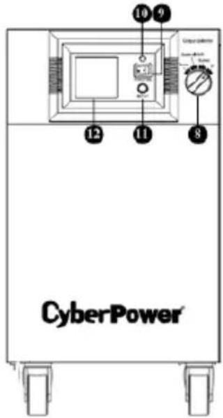
CPS3500PIE/CPS5000PIE
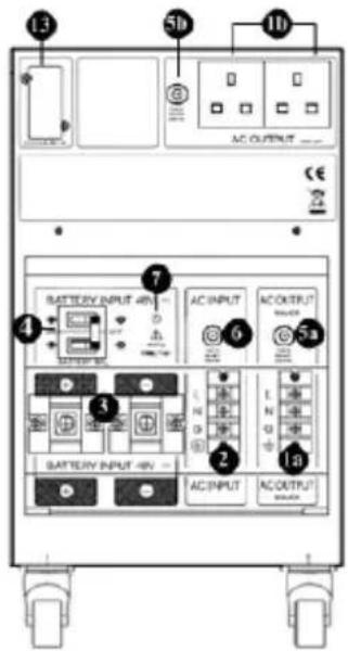
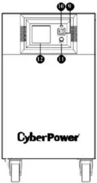
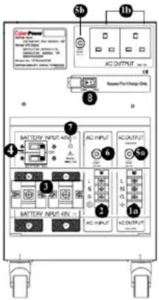
DESCRIPTION
1. AC Outlets
EPS PRO/PIE Series have two general plug-in outlets (UK/Schuko/ France) and one terminal outlet for connected equipment which ensures temporary uninterrupted operation of the equipment during a power failure.
Max. Output of 1a is 40A; Max. Output of 1b is 12A for UK socket, 16A for Schuko/France socket.
Max. Output wattage of (1a+1b) is 2450W (CPS3500PIE/CPS3500PRO Series)/ 3500W (CPS5000PIE /CPS5000PRO Series).
*Note: Maximum cord length is 10 meters and the cable O.D. must be 10AWG (CPS3500PIE/CPS3500PRO & CPS5000PIE/CPS5000PRO Series) or greater.
2. AC Inlet
AC input terminals
*Note: The O.D. of the distribution cables must be 10AWG (CPS3500PIE/CPS3500PRO & CPS5000PIE/CPS5000PRO) or greater.
3. DC Inlet
Battery input terminals
*Note: Maximum battery wiring cable length is 2 meters and the cable O.D. must be 4AWG or greater.
4. DC Circuit Breaker
Located on the side of the EPS, the circuit breaker serves to provide overload and fault protection.
*Note: It is used as INPUT BATTERY SW as well.
5. AC Output Circuit Breaker
Located on the side of the EPS, the circuit breaker serves to provide overload and fault protection.
*Note: Circuit breaker 5a provides max 40A protection for 1a socket.
*Note: Circuit breaker 5b provides max 12A protection for UK socket or 16A for Schuko/France socket.
6. AC Input Circuit Breaker
Located on the side of the EPS, the circuit breaker serves to provide overload and fault protection.
7. Battery Input Wiring Fault LED
Battery input wiring fault LED will illuminate and make an audible alarm to indicate the wiring polarity is reversed only when the DC circuit breaker is off.
*Note: Please make sure the DC circuit breaker is off before connecting the battery to the machine.
8. Output Selector
For PRO series, Output Selector provides four most common operation situations for switch include Normal, Bypass with AVR, Bypass and Off. No matter under what situations, the charger would keep charging external batteries if utility power is still alive.
Normal: The unit will provide all functions of uninterruptible power supply include charger.
Bypass with AVR: The unit will bypass the utility power with voltage regulator and shutdown the unit when the utility power exceeds 300Vac or below 140Vac.
Bypass: The unit will bypass the utility power to output directly.
*Note: Bypass model would not provide any overvoltage protection .Utility power may damage equipment plugged to EPS. Make sure equipment safe before switch to this model.
Off: The unit will interrupt all outlets power output.
*Note: The charger would still work under these four switch modes.
*For PIE Series, the unit provides specific Bypass function.
Bypass: The switch provides the bypass for charge only and shutdown the unit when the utility power exceeds 300Vac or below 140Vac. In charger only mode, AVR and battery backup will not work.
9. Power Switch
Used as the master on/off switch for equipment connected to the battery power supplied outlets.
10. Power ON Indicator
This LED is above the power switch. It illuminates when the utility condition is normal and the EPS outlets are providing power, free of surges and spikes.
11. LCD Display Toggle / Selected Switch
Users can monitor EPS status and set up functions by using the toggle.
12. Multifunction LCD Readout
High resolution and intelligent LCD display shows all the EPS information with icons and messages. For more information please check the DEFINITIONS FOR ILLUMINATED LCD INDICATORS section.
13. SNMP/DB9/USB Network slot (only for PRO series)
Remove the cover panel to install optional SNMP/DB9/USB CARD that allows remote monitoring and control of your EPS through network or cable.
INSTALLATION GUIDE
Note: The installation must be done by professionals.
- Remove the cover from the back of the machine.
- Make sure the POWER SW, Output Selector, and the BATTERY SW. are turned off. (Step1)
Step 1
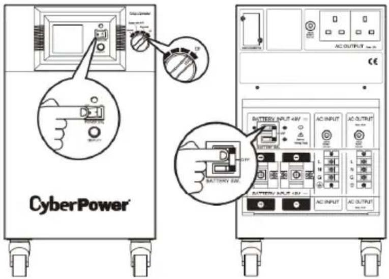

For PRO series, the EPS will not function if the Output Selector is off. Make sure the Selector on Normal position after all installation procedures.
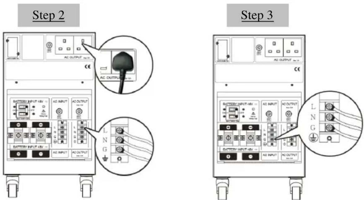
- Connect the AC OUTPUT connections (AC plugs or terminal connections). (Step2)
- Connect the AC power source to AC INPUT (Make sure AC power is off first). (Step3)
Step 4
Step 5
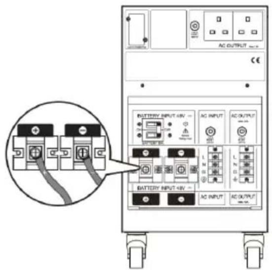
- Connect the batteries to the BATTERY INPUT. (Step4)

WIRING FAULT LED will illuminate and make an audible alarm to indicate the wiring polarity is reversed only when the DC circuit breaker is off.
*Note: Please make sure the DC circuit breaker is off before connecting the battery to the machine.
-
If the battery box or the battery connection has a switch, please turn it on first.
-
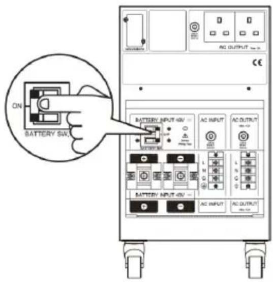
Turn on the BATTERY SW. on the back of the machine (Step 5)
-
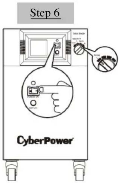
Turn on the Power Switch and switch the Output Selector to Normal on the front panel. The Power On Indicator and the LCD Module Display will blink 4 times. Press the Display Toggle (Selected Switch) once. The output voltage showing on the LCD Module Display should be 220V. This completes the start-up process. (Step 6)
-
Press and hold the Display Toggle switch for 4 seconds then release. The machine will begin a self test and enter Battery Mode for 6 seconds before returning to Line Mode. Make sure the self test is ready, or see the Definitions for illuminated LCD on page 13 for a list of alarm code definitions.
-
After ensuring the machine works normally, reassemble the back cover. The installation is now complete.
-
When the external battery needs to be maintained or replaced, remember to turn the machine off. Once off, remove the AC power source and switch off the BATTERY SW. before maintenance or replacing the batteries. When the work is complete, please start from Step 1 to re-install the machine.
DEFINITIONS FOR ILLUMINATED LCD
The LCD Display indicates a variety of EPS operational conditions. All descriptions apply when the EPS is plugged into an AC outlet and turned on or when the EPS is on battery.
-
INPUT VOLTAGE Meter: This meter measures the AC voltage that the EPS is receiving from the utility wall outlet. The EPS is designed, through the use of automatic voltage regulation, to continuously supply connected equipment with stable 220 output voltage. In the event of a complete power loss, severe brownout or over-voltage, the EPS will rely on its external battery to supply consistent 220 output voltage. The Input Voltage Meter can be used as a diagnostic tool to identify poor quality input power.
-
OUTPUT VOLTAGE Meter: This meter measures the AC voltage that the EPS is providing to the connected equipment. It displays normal line mode, AVR mode, and battery backup mode.
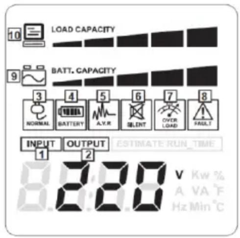
- NORMAL MODE Icon: This icon will illuminate when the EPS is working under normal conditions.
- ON BAT (On Battery) Icon: When a severe brownout or blackout occurs, this icon illuminates and an alarm sounds (2 short beeps followed by a pause) to indicate the EPS is operating from its external batteries. During a prolonged brownout or blackout, the alarm will sound continuously. When the BATTERY CAPACITY Meter shows one 20% capacity segment remaining it indicates the EPS's external batteries are nearly out of power. You should save files and shut down your equipment immediately.
- AVR (Automatic Voltage Regulator) Icon: This icon will illuminate whenever your EPS is automatically correcting high or low AC line voltage. This is a normal, automatic operation of your EPS, and no action is required on your part.
- SILENT MODE Icon: This icon illuminates whenever the EPS is in silent mode. The buzzer will not beep during the battery mode until the battery reaches low capacity.
- OVER LOAD Icon: This icon will illuminate and an alarm will sound to indicate the battery supplied outlets are overloaded. To clear the overload, unplug some of your equipment from the battery supplied outlets until the icon is no longer illuminated and the alarm stops.
-
FAULT MODE Icon: This icon illuminates if there is a problem with the EPS. Please contact CyberPower Systems or local agent for further help and support.
-
BATTERY CAPACITY Meter: This meter displays the approximate charge level (in 20% increments) of the EPS's external battery. During a blackout or severe brownout, the EPS will switch to battery power, the ON BAT icon will be illuminated, and the charge level will decrease.
- LOAD CAPACITY Meter: This meter displays the approximate output load level (in 20% increments) of the EPS's battery outlets.
EPS Status Inquiry and Functions Setup
1. General Mode
a. Press the LCD Display Toggle (Selected Switch) to check the status of the EPS.
| Item | Unit |
| Input Voltage | V |
| Output Voltage | V |
| Output Frequency | Hz |
| Load | Kw |
| Load Capacity | % |
| Battery Capacity | % |
| Centigrade | °C |
| Fahrenheit | °F |
b. Press and hold the Display Toggle for 4 seconds.
- If the machine is in the Battery Mode, it enters/leaves Silent Mode.
- If the machine is in the Line Mode, it proceeds to Self Test.
c. If the Display Toggle remains untouched for over 30 seconds, the LCD backlight will turn off automatically.
2. Set-up Mode
Step 1: The machine enters Set-up Mode after the Display Toggle is pressed and held for 10 seconds. When icons 4, 5, 6, 7, 8, 9 (see page 8) all illuminate, the EPS is in the Set-up Mode.
Step 2: By pressing the Display Toggle, users can switch setup functions:
| Items | Unit |
| Delay Time | Min |
| Battery Capacity | H |
| Charging Current | A |
| Nominal Output Voltage | V |
| Static Frequency Tolerance | % |
| Slew Rate | % |
| Battery Shutdown Voltage | V |
| Mode Select | None |
| Firmware Version | None |
| Last Shutdown Event | None |
a. Delay Time: The time delays for switching from Battery Mode to Line Mode. The machine will switch from Battery Mode to Line Mode within the preset delay time after the AC power transmission reaches stability.
Default 0.0 minutes Choice 0.0, 0.5, 1.0, 1.5, 2.0, 2.5, 3.0, 3.5, 4.0 minutes
b. Battery Capacity: The function adjusts the battery capacity of the used batteries.
Default 100AH Choice 50, 75, 100, 150, 200AH, others (0H)
Note: The default value would be 100AH unless the capacity of the EPS bundling battery is not 100AH. In this case, the default value changes according to the capacity of the bundling battery. For more information, please see page 11 BATTERY CHARGING SETTING ARRANGEMENT.
c. Charging Current: The function adjusts the current for battery charging.
Default Medium level Choice Lowest, Low, Medium, High level
Note: Check the setting of battery capacity before setting the charging current as the default value varies according to the battery capacity. For more details, please see page 11 BATTERY CHARGING SETTING ARRANGEMENT.
d. Nominal Output Voltage: AVR Dynamic Voltage Compensation works automatically based on the system voltage settings. Please configure the correct electricity/voltage supplied in the area/country where the EPS will be used.
Default 220V Choice 220, 230, 240V
e. Static Frequency Tolerance: The settings may be adjusted to the quality of the electricity in use.
Default +/-10% Choice 1, 2, 4, 6, 8, 10%
f. Slew Rate (Dynamic Frequency Tolerance): Slew Rate indicates the tolerance of a device in accepting frequency variances. The lower Slew Rate results in less tolerance but better protection for the connected loads.
Default 4Hz/sec Choice 0.25, 0.5, 1, 2, 4 Hz/Sec
g. Battery Shutdown Voltage: This function adjusts the EPS shutdown point according to the battery voltage.
Default CPS5000 - 44V / CPS3500 - 22V Choice CPS5000 - 38, 40, 42, 44V / CPS3500 - 19, 20, 21, 22V
Note: In order to extend the lifespan of the battery, the function is applicable only when load ≥ 75%.
h. Mode Select: Using the generators as ESP input is suggested to select the Robust Mode (1); using the computers as EPS output is suggested to select the Standard Mode (2).
Default Robust (1) Choice Robust (1), Standard (2)
i. Firmware Version: This function shows the version of the used firmware.
j. Last Shutdown Event: This function shows the latest record of error codes, if any.
Note: For more information about error codes, please see the table on page 14.
Step 3: Press and hold the toggle for 4 seconds. When the icons blink, the value of each item can be changed by slightly pressing the toggle.
Step 4: To save the value and return to general mode, press and hold the toggle for 4 seconds.
Note: If the machine is left idle for over 30 seconds during setup, it will turn off the backlight and return to general mode automatically.
Note: If user wants to return to general mode without saving changes, there are two methods:
- Wait for the backlight to turn off
- Press and hold the Display Toggle for 10 seconds
BATTERY CHARGING SETTING ARRANGEMENT
Please read the following instructions and cautions carefully before charging the battery.
Step 1: Press the LCD Display Toggle (Selected Switch) on the front panel for 10 seconds and let the EPS enter Set-up Mode.
Step 2: By pressing the Display Toggle, switch setup function to Battery Capacity / Charging Current.
Step 3: Press and hold the toggle for 4 seconds. When the icons blink, slightly press the toggle to choose the value of the battery capacity / charging current. Please refer to the following table for suitable setting.
| LOWEST | LOW | MEDIUM (default) | HIGH | |||||
| current | time* | current | time | current | time | current | time | |
| 50 AH | 3A | 30hr | 6A | 11hr | 8A | 9hr | ||
| 75 AH | 4A | 30hr | 10A | 11hr | 13A | 9hr | ||
| 100 AH | 5A | 30hr | 10A | 15hr | 14A | 11hr | 17A | 9hr |
| 150 AH | 8A | 30hr | 15A | 15hr | 21A | 11hr | 26A | 9hr |
| 200 AH | 10A | 30hr | 20A | 15hr | 28A | 11hr | 35A | 9hr |
| Others (0H)** | 5A (default), 10A, 15A, 20A, 25A, 30A, 35A, 40A, 45A, 50A | |||||||
* Time here indicates charging hours needed for the battery.
** Due to the fact that the inappropriate charging current will seriously cause the decrease of the lifespan of the battery, please DO NOT use the 0H setting without the assistance from local agent. Improper use is not incorporated in the warranty.
Step 4: Press and hold the toggle for 4 seconds to save the setting value and return to general mode.
CAUTION! The following statements related to the battery warranty are highly important. Please read and abide by them carefully.
- Do not set the inappropriate battery capacity. Incorrect charging current will seriously affect the cycle use of the battery.
- Use LOWEST/LOW current level for setting if the flooded battery is used.
● Assess if the battery can withstand the charging current before you adjust the original current level to a larger one. Unsuitable use will seriously impact on the battery lifespan.
The battery warranty becomes not applicable when one of the rules is violated. For more information, please contact the local agent.
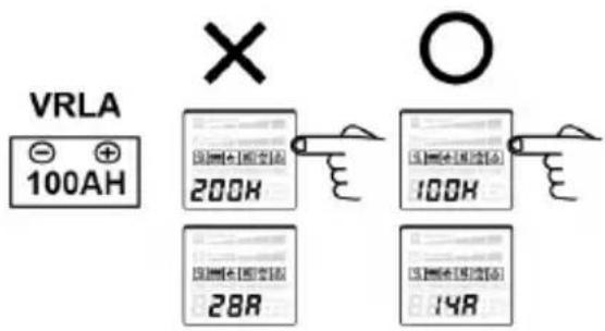
Please set the correct battery capacity
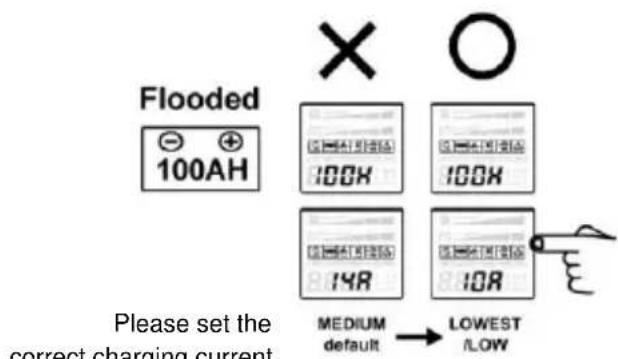
CAUTION! Too large charging current, overcharge and that the battery is not fully charged for a long time all have impact on the lifespan of the battery. Please carefully assess the battery type, capacity, charging current and discharging and charging time needed. For more information, please contact the local agent.
CAUTION! BATTERY LIFESPAN will be influenced by several factors, such as the number of discharging and recharging cycles and the ambient temperature. It is recommended to follow the suggestions below to increase the lifespan of the battery.
- Setting too large charging current will decrease the battery lifespan. Please choose the suitable setting from the table on page 11 to meet your needs.
- Keep the battery fully charged, even when it is not in use.
- Do not expose the battery to high temperature environment, such as direct sunlight. It will seriously decrease the efficiency of the battery.
- The lifespan of the battery gets a drop-off when the ambient temperature is getting higher above 77°F/25°C, which is the optimum temperature for the battery. Keep the ambient temperature at the optimum temperature.
- Do not deploy batteries with different manufacturing batch (different production date). Mix usage of batteries with different remaining power (voltage) will cause unbalanced charge voltage and will shorten the lifespan of batteries.
● The voltage differences of one set of batteries shall be within 0.3V. If not, change the unsuitable batteries in order not to cause unbalanced charge. It will shorten the lifespan of batteries.
FAULT WARNING DISPLAY AND ALARM
- The following table shows each corresponding warning message on the LCD display and the alarm reacts during the machine shutdown :
| LCD Warning Display | Alarm | Condition | Solution |
 | Long Beep | Overload | Check total load to confirm the rating of EPS. |
 (Flashing) (Flashing) | Rapid Beep (30s) | Battery missing in Line Mode | Turn the EPS off. Check battery wiring and the presence of the battery. |
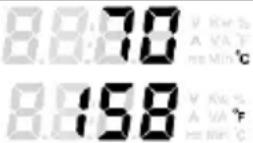 | Rapid Beep | Overheat (Over 70°C/158°F) | Check fans function and air vent clearances. |
| [H62Y]BATT. CAPACITY | Rapid Beep | Low Battery. Battery Capacity shows 0% In General Mode. | Recharge the battery. |
 [Y4][357K][3XSW] [Y4][357K][3XSW] | Rapid Beep | Overcharge in Line Mode | Inform service agents. |
After warning, all above except "Battery missing in Line Mode" will all shut down. For "Battery missing in Line Mode", the On Battery icon will keep flashing.
- The following table shows the information about the error codes on the LCD display AFTER the machine shutdown. The LCD will show the message till the EPS runs out of battery.
| Error Type | Error Code | Possible cause | |
| Line Mode Error | E0 | AVR Fail | AVR broke down |
| E1 | Battery Overcharge | Charger broke down | |
| Battery Mode Error | E10 | Output Overvoltage | Output voltage detector broke down |
| E11 | Battery Overvoltage | Unexpected battery module | |
| System Error | E20 | Battery Mode No Output Voltage | EPS/connected devices short circuit |
| Output voltage detector broke down | |||
| Inverter broke down | |||
| E21 | Utility Mode No Output Voltage | EPS/connected devices short circuit | |
| Output voltage detector broke down | |||
| Input relay broke down | |||
| E22 | Output Overload | Too many connected devices | |
| Output voltage detector broke down | |||
| E23 | Transformer Overheat | Over temperature of Transformer | |
| E24 | Inverter Overheat | Over temperature of Heat Sink | |
| E25* | Turned Off By EPO | Shutdown by EPO | |
| E26 | AC Input Over Current | Low AC input voltage | |
| E27 | Abnormal Input Current Feedback | Input current sensor broke down | |
| E28 | Abnormal Output Current Feedback | Output current sensor broke down | |
*It is only for the products equipped with EPO.

After the EPS shutdown, the Fault Mode icon will also illuminate on the LCD display together with the error code, indicating there is a problem with the machine. Please contact CyberPower Systems or local agent for further help and support.
REPLACING BATTERY
CAUTION! Read and follow the IMPORTANT SAFETY INSTRUCTIONS before servicing the battery. Battery service should only be done by qualified professionals.
CAUTION! Use only the specified type and number of external batteries. Please see the technical specifications for replacement batteries. Mix usage of different brands, capacity and type of battery will cause damage to batteries because the suitable charging current of each battery may be different.
CAUTION! Deploying batteries with different manufacturing batch (different production date) is not recommended. Mix usage of batteries with different remaining power (voltage) will cause unbalanced charge voltage and will shorten the lifespan of batteries.
CAUTION! The voltage differences of one set of batteries shall be within 0.3V. If not, change the unsuitable batteries in order not to cause unbalanced charge. It will shorten the lifespan of batteries.
CAUTION! The battery may present a risk of electrical shock. Do not dispose of battery in a fire as it may explode. Follow all local ordinances regarding proper disposal of batteries. Lead-acid batteries should be recycled.
CAUTION! Do not open or mutilate the batteries. Released electrolyte is harmful to skin and eyes. It may be toxic.
CAUTION! The external battery cabinet must be provided with 80V / 100A x2 for models CPS3500PIE, CPS3500PRO, CPS5000PIE and CPS5000PRO of DC protective device. CPS3500PIE Series include CPS3500PIE、CPS3500PIE-FR、CPS3500PIE-UK and other versions. CPS3500PRO Series include CPS3500PRO、CPS3500PRO-FR、CPS3500PRO-UK and other versions. CPS5000PIE Series include CPS5000PIE、CPS5000PIE-FR、CPS5000PIE-UK and other versions CPS5000PRO Series include CPS5000PRO、CPS5000PRO-FR、CPS5000PRO-UK and other versions
CAUTION! A battery can present a risk of electrical shock and high short-circuit current. The following precautions should be observed when working on batteries:
- Remove watches, rings, or other metal objects.
- Use tools with insulated handles.
- Wear rubber gloves and boots.
- Do not lay tools or metal parts on top of batteries.
- Disconnect charging source prior to connecting or disconnecting battery terminals.
- Determine if battery is inadvertently grounded. If inadvertently grounded, remove source from ground. CONTACT WITH ANY PART OF A GROUNDED BATTERY CAN RESULT IN ELECTRICAL SHOCK. The likelihood of such shock can be reduced if such grounds are removed during installation and maintenance (applicable to equipment and remote battery supplies not having a grounded supply circuit).
TROUBLESHOOTING
| Problem | Possible Cause | Solution |
| Outlet does not provide power to equipment. | Circuit breaker has tripped due to an overload. | First, turn the EPS off and unplug at least one piece of equipment. Wait 10 seconds, reset the circuit breaker by pressing the button, and then turn the EPS on. |
| Batteries are discharged. | Recharge the unit for at least 4 hours. | |
| Unit has been damaged by a surge or spike. | Contact CyberPower Systems or local agent about replacement batteries. | |
| The EPS cannot be turned on. | The on/off switch is designed to prevent the damage that rapidly turns it off and on. | Turn the EPS off. Wait 10 seconds and then turn the EPS on. |
| The unit is not connected to an AC outlet. | The unit must be connected to a 220/230/240v outlet. | |
| The battery is worn out. | Contact CyberPower Systems or local agent about replacement batteries. | |
| Mechanical problem. | Contact CyberPower Systems or local agent via phone or visit our website. | |
| Input and output wiring error | Check the input/output connection. | |
| The battery voltage is too high during cold start. | Check the reason for battery over-voltage. | |
| Software is inactive to EPS | The serial cable or USB cable is not connected. | Connect the cable to the EPS. The cable that came with the unit shall be used. |
| The cable is connected to the wrong port. | Try another port of your computer. | |
| The serial cable is not the cable that was provided with the unit. | You must use the cable included with the unit for the software. |
TECHNICAL SPECIFICATIONS
| Model | CPS3500PIE | CPS3500PRO | CPS5000PIE | CPS5000PRO |
| Capacity (VA) | 3500VA | 5000VA | ||
| Capacity (Watts) | 2450W | 3500W | ||
| Operation Technology | AVR (Single Boost & Single Buck) | |||
| AC Input | ||||
| Input Voltage Range | 140Vac - 300Vac | |||
| Input Frequency Range | 50/60 Hz +/- 5 Hz (auto sensing) | |||
| AC Output | ||||
| Phase | Single Phase | |||
| Output Voltage | Pure Sine Wave at 220Vac +/- 10% | |||
| Nominal Output Voltage | Configurable for 220 : 230 : 240Vac | |||
| Battery Output Frequency | 50 / 60 Hz +/- 1% | |||
| Overload Protection | On Utility: Circuit BreakerOn Battery: Internal Current Limiter | |||
| Transfer Time | < 10 ms (Typical) | |||
| Output Receptacles | UK(Schuko/France) Type*2 + Terminal Block | |||
| External Battery | ||||
| Voltage x Recommended Rating X Quantity | 12V x 200AH X 2 | 12V x 200AH X 4 | ||
| External Battery Voltage | 24V | 48V | ||
| External Battery Type | Sealed Maintenance Free Lead Acid Battery | |||
| External Battery Protection | DC Circuit Breaker | |||
| Hot Swappable | Yes | |||
| Extended Runtime | Yes | Yes | ||
| Status Indication | ||||
| Indicators | Power On, LCD Display | |||
| Audible Alarms | On Battery, Low Battery, Overload, Overheat, Overcharge | |||
| Environmental | ||||
| Temperature | 32°F to 104°F (0°C to 40°C) | |||
| Relative Humidity | 0 to 95% Non-Condensing | |||
| Physical | ||||
| Dimensions (LxWxH) (mm) | 330 x 260 x 440 | |||
| Weight (Kg) | 36 Kg | 44 Kg | ||
| Safety | ||||
| Certificated | CE/SONCAP | |||
Scope and User Object
The EPS is used in low-voltage TN/IT distribution systems and is intended to be installed in any operator accessible area.
All people coming into contact with the EPS shall read above all information (page 1 to page 18). However, in general, the followings are not taken into account.
- People with physical, sensory or mental disabilities
- People without using experience or knowledge
- Children
In order to keep them away from danger, please prevent them from using the equipment without supervision or instruction. Plus, after the installation of the EPS, castors must be blocked in a way to remove possible movement.
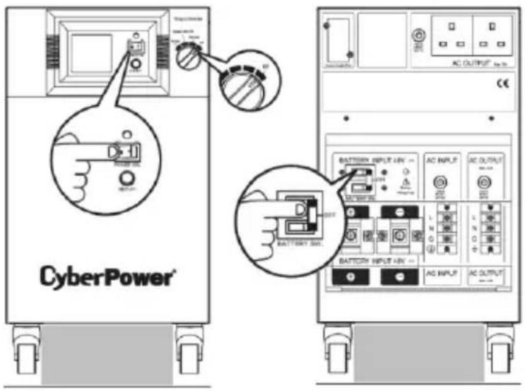
Step 1: Turn off the POWER SW, Output Selector and the BATTERY SW.
Step 2: Put an appropriate cushion/stuff under the machine in order to fix the EPS and keep it steady during operation.
Step 3: Follow the instructions on the manual, turning on the POWER SW, Output Selector and the BATTERY SW.
Note: For user's safety, the above steps shall be done by trained people after the installation of the EPS.
CyberPower® Reliability Quality Value
Reliability. Quality. Value.
For more information, contact us at:
CyberPower Systems, Inc.
Website: www.cpsww.com
- User's Manual
- CPS3500PIE/CPS3500PRO
- CPS5000PIE/CPS5000PRO
- SAFETY AND EMC INSTRUCTIONS
- DO NOT USE FOR MEDICAL OR LIFE SUPPORT EQUIPMENT!
- DO NOT INSTALL THE EPS WHERE IT WOULD BE EXPOSED TO DIRECT SUNLIGHT OR NEAR HEAT!
- DO NOT CONNECT DOMESTIC APPLIANCES SUCH AS HAIR DRYERS TO EPS OUTPUT SOCKETS.
- INSTALLING YOUR EPS
- UNPACKING
- AUTOMATIC VOLTAGE REGULATOR
- HARDWARE INSTALLATION GUIDE
- BASIC OPERATION
- DESCRIPTION
- AC Outlets
- AC Inlet
- DC Inlet
- DC Circuit Breaker
- AC Output Circuit Breaker
- AC Input Circuit Breaker
- Battery Input Wiring Fault LED
- Output Selector
- Power Switch
- Power ON Indicator
- LCD Display Toggle / Selected Switch
- Multifunction LCD Readout
- SNMP/DB9/USB Network slot (only for PRO series)
- INSTALLATION GUIDE
- DEFINITIONS FOR ILLUMINATED LCD
- EPS Status Inquiry and Functions Setup
- General Mode
- Set-up Mode
- BATTERY CHARGING SETTING ARRANGEMENT
- FAULT WARNING DISPLAY AND ALARM
- REPLACING BATTERY
- Scope and User Object
- CyberPower® Reliability Quality Value
Brand : CyberPower
Model : CPS5000PRO
Category : Air Conditioning