
Perfect Position COH-400 - Heating CUISINART - Free user manual and instructions
Find the device manual for free Perfect Position COH-400 CUISINART in PDF.


| Product Type | Heater |
| Brand | Cuisinart |
| Model | Perfect Position COH-400 |
| Dimensions | Approximately 10.6 x 9.1 x 13.4 inches (27 x 23 x 34 cm) |
| Weight | Approximately 3.5 lbs (1.6 kg) |
| Power Supply | 120V AC, 60Hz |
| Power Consumption | 1500W (max) |
| Heat Settings | High (1500W) and Low (750W) |
| Fan Only Mode | Yes |
| Thermostat | Adjustable thermostat |
| Oscillation | No |
| Adjustable Angle | Yes, tilts up to 90 degrees |
| Safety Features | Overheat protection, tip-over automatic shut-off, cool-touch housing |
| Heating Element | PTC ceramic |
| Control Type | Push-button controls with indicator lights |
| Remote Control | Included |
| Timer | 1-12 hours auto shut-off |
| Noise Level | Quiet operation |
| Filter | Washable pre-filter |
| Maintenance | Clean grille and filter regularly; unplug before cleaning |
| Spare Parts | Replacement filters available from Cuisinart |
| Warranty | 3-year limited warranty |
| Certifications | ETL listed |
Frequently Asked Questions - Perfect Position COH-400 CUISINART
User questions about Perfect Position COH-400 CUISINART
0 question about this device. Answer the ones you know or ask your own.
Ask a new question about this device
Download the instructions for your Heating in PDF format for free! Find your manual Perfect Position COH-400 - CUISINART and take your electronic device back in hand. On this page are published all the documents necessary for the use of your device. Perfect Position COH-400 by CUISINART.
USER MANUAL Perfect Position COH-400 CUISINART
- Shut off gas to the appliance.
- Extinguish any open flame.
- If odor continues, keep away from the appliance and immediately call your gas supplier or fire department.
Failure to follow these instructions could result in fire or explosion, which could cause property damage, personal injury, or death.

DANGER
Do not store or use gasoline or other flammable vapors and liquids in the vicinity of this or any other appliance.
A propane-cylinder not connected for use shall not be stored in the vicinity of this or any other appliance.

WARNING
Improper installation, adjustment, alteration, service or maintenance can cause property damage, injury or death.
Read the installation, operating and maintenance instructions thoroughly before installing or servicing this equipment.

WARNING: For Outdoor Use Only.
Installation and service must be performed by a qualified installer, service agency, or the gas supplier.

DANGER

CARBON MONOXIDE HAZARD
This appliance can produce carbon monoxide which has no odor.
Using it in an enclosed space can kill you.
Never use this appliance in an enclosed space such as a camper, tent, car or home.

natural_image
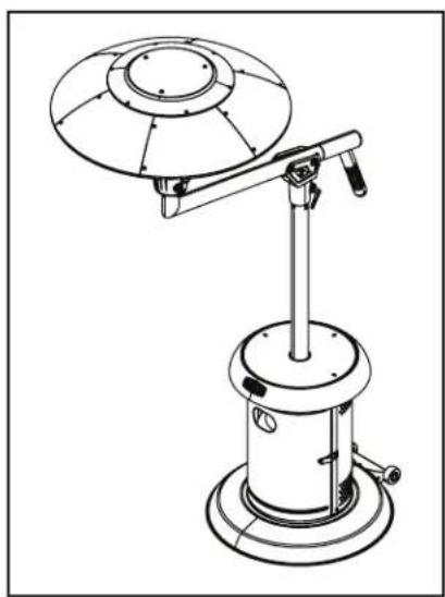
Line drawing of a portable outdoor lighting fixture with a canopy and support structure (no text or symbols)Customer Service Hotline
1-866-994-6390
DO NOT RETURN PRODUCT
TO THE STORE
Before visiting your local retailer, please email grilling@thefulhamgroup.com, call 1-866-994-6390, or visit www.thefulhamgroup.com to online chat with a representative. To best serve you, our Representatives are available to answer your calls and live chats Monday to Friday, 9 AM - 5 PM EST.
INSTALLER: Leave this manual with the appliance. CONSUMER: Retain this manual for future reference.
CALIFORNIA PROPOSITION 65 WARNING:
- WARNING: FUELS USED IN LIQUEFIED PROPANE GAS APPLIANCES, AND THE PRODUCTS OF COMBUSTION OF SUCH FUELS, CAN EXPOSE YOU TO CHEMICALS INCLUDING BENZENE, WHICH IS KNOWN TO THE STATE OF CALIFORNIA TO CAUSE CANCER AND CAUSE BIRTH DEFECTS OR OTHER REPRODUCTIVE HARM.
For more information go to: www.P65Warnings.ca.gov.
IMPORTANT: ALL INSTRUCTIONS AND SAFEGUARDS ON THIS SECTION MUST BE FOLLOWED TO PREVENT DAMAGE AND/OR INJURY.
USE CAUTION AND COMMON SENSE WHEN USING YOUR OUTDOOR PATIO HEATER. FAILURE TO ADHERE TO THE SAFETY WARNING AND GUIDELINES IN THE MANUAL COULD RESULT IN BODILY INJURY OR PROPERTY DAMAGE. SAVE THIS MANUAL FOR FUTURE REFERENCE.
SAFETY INFORMATION
- Do not allow children to climb the product.
• After a period of storage, inspect the patio heater for abrasion, wear or damage. - Do not operate this patio heater while under the influence of drugs, alcohol, or while fatigued.
- Do not use this patio heater unless it is completely assembled, and all parts are securely fastened and tightened.
- Never use under low hanging tree branches, trellises or overhangs of any kind including covered porches.
- Always use patio heater in accordance with all applicable local, state, and national codes. Contact your local fire department for details.
- DO NOT move this product when in use.
- Any modification of this appliance may be dangerous and will void the warranty.
- NEVER operate the heater with the top half covered (burner head, reflector, etc.).
- DO NOT leave this product unattended when in use.
- Always keep the cylinder level and vertical when positioning inside the base.
- ONLY use this appliance on a flat, LEVEL, nonflammable surface or ground.
- When positioning, ensure the unit is a minimum of 40 in. (1 m) from flammable items or structure from all sides and above.
- Always leak test the unit before use, annually, or after storage, when parts are replaced/serviced or if the gas cylinder is removed or replaced.
- When storing the appliance or gas cylinder, ensure they are away from flammable materials or liquids.
- Regularly check that the regulator seal and hose is fitted and that it is in good condition. Replace parts if necessary.
- Always follow the care and maintenance instructions – regularly maintain your appliance.
- Always replace worn parts – do not use the appliance if a leak, wear, or damage is found.
- DO NOT store or cover the appliance until fully cooled.
• Always shut off the valve at the gas cylinder or the regulator before moving the appliance. - In the event of high winds particular attention must be taken. Store the unit away or ensure it is at a safe distance from other items in the event that the unit is blown over.
- Only use with gazebos specifically designed to be used with patio heaters.
- It is normal for the heater to smoke during the first few minutes of use.
- If you smell gas – turn off the appliance, disconnect from propane tank, and extinguish all flames. If the odor continues, immediately contact your gas supplier.
-
In the event of an uncontrollable fire, immediately disconnect and shut off the gas cylinder, move the gas cylinder away from the fire, and contact the fire department. DO NOT PUT YOURSELF AT RISK!
-
Ensure aerosols are not used near this unit when in use.
- Ensure all packaging and plastic bags are disposed of safely.
- Ensure the heater is at a safe distance from glass and PVC doors and windows to stop damage from any heat.
- Read the warnings and use instructions before operation.
- Do not leave the lantern head in the upright position during rain or windy conditions or when the patio heater is not in use or unattended. Always fold down the lantern head when not in use or during windy or rainy conditions.
- This appliance features a flame failure and tilt device. In the event of a wind blowing the flame out or the unit being tipped over, the gas supply will be cut off from the cylinder. In this event, the knobs should be set to off and you should wait 5 minutes before re-lighting.
- This product will become hot when in use – take care when touching.
- Keep children and pets at a safe distance from the unit when in use.
- The outdoor patio heater is for adult use only.
- Keep the area around the patio heater clear and free of any combustible materials, gasoline, or any other flammable liquids. Do not use patio heater in an explosive environment.
- Before each use make sure the patio heater is in good working condition. Inspect the hose and the unit itself.
- Never fold down the lantern head while the heater is operating.
- Warning: Upper Support Pole and top burner unit will get hot while in use. Use caution when handling.
- Do not store or use gasoline or any other flammable vapors or liquids in the vicinity of the patio heater.
- NEVER use indoors, in an enclosed area or below ground level.
- This appliance is intended for use with propane bottled gas only.
- Failure to read and follow these instructions could result in serious injury or damage to property.
- Wait until the unit has fully cooled before folding down the lantern head.
- Disconnect the gas cylinder and remove the gas cylinder from the heater before folding down the lantern head.
• Take care to support the lantern head while folding it down so that it does not drop suddenly. - It is recommended that two people handle the heater when folding down the lantern head.
- Serious injury, death, and/or properly damage may occur if the above instructions are not followed exactly.
- NOTE: THESE INSTRUCTIONS ARE FOR YOUR SAFETY. PLEASE READ THEM THOROUGHLY BEFORE USE AND RETAIN THEM FOR FUTURE REFERENCE.
- WARNING: Do not raise or lower the arm and burner head on an inclined surface. Dropping the burner head or boom arm will change the center of gravity, the unit is meant to be used on a flat, hard, level surface only.
- WARNING: Tighten the swivel neck before raising or lowering arm. Do not raise the arm when the swivel neck is loose.
- WARNING: Lowering the arm can create a pinch point, keep all body parts out of the path of travel.
- WARNING: When lowering the arm, do it slowly to allow the burner head to drop in a controlled manner. Allowing the burner head to drop suddenly will result in damage and/or personal injury.
- WARNING: Do not light heater when burner is lowered as this could result in result in damage and/or personal injury.
- WARNING: Do not pull out, pull on, fray, bend, twist or cut the regulator hose at the arm junction as this could result in damage and/or personal injury.
- WARNING: Do not operate this heater without studying the entire contents of this document. Failure to do so could lead to misuse resulting in damage and/or personal injury.
- CAUTION: Do not use heater if it shows any sign of damage.
SAFETY INFORMATION
- CAUTION: Do not touch the heating dome when burner is in operation, allow to cool down completely before touching.
- CAUTION: Do not walk under burner head while it is in raised position.
- WARNING: Before allowing anyone to operate the heater, be certain that they have fully understood the manual.
- CAUTION: Keep people, children and pets clear while lifting or dropping the burner head.
- WARNING: Keep fingers and clothing clear of moving parts.
- WARNING: Loads, clothing and items shall not be placed, hung, or spread on burner head arm.
- WARNING: When in operation, lock swivel neck to limit movement.
- WARNING: When moving heater, lock swivel neck to limit movement.
- CAUTION: Do not stand on the table. It is only designed to hold food and drinks i.e. plates, cups, and bottles.
- CAUTION: Lock tank door when moving heater.
- CAUTION: Lock tank door when using heater.
- NOTE: Failure to heed any of the above can result in personal injury and/or damage.
- When an appliance is for connection to a gas cylinder, the installation shall conform with local codes or, in the absence of local codes, with AMSI Z223.1/NFPA 54,CSA B149.1,or CAS B149.2.
TABLE OF CONTENTS
Cover Page....1
Safety Information....2
Table of Contents....5
Exploded View....6
What's in the Box....7
Assembly Instructions....9
Operation....17
Care and Maintenance....22
Warranty and Replacement Parts....23
EXPLODED VIEW
Carefully remove all pieces from the carton and make sure that you have all parts listed (refer to components list). If you are missing parts, please contact 1-866-994-6390 for further assistance.
Use caution when removing the parts from packaging. It is recommended to wear gloves when assembling and handling loose parts.

COMPONENTS
| PART DESCRIPTION QTY | ||
| 1 Base (x1) | ||
| 2 Cylinder Chamber Supports (A, B, C) (x3) | ||
| 3 Lower Support Pole (x1) | ||
| 4 Cylinder Chamber Wall (x1) | ||
| 5 Cylinder Chamber Door (x1) | ||
| 6 Cylinder Chamber Top (x1) | ||
| 7 Swivel Head (x1) | ||
| PART DESCRIPTION QTY | ||
| 8 Upper Support Pole (x1) | ||
| 9 Main Burner and Hose (x1) | ||
| 10 Burner Mesh (x1) | ||
| 11 | Parasol Supports | (x3) |
| 12 | Handle | (x1) |
| 13 Regulator (x1) | ||
| 14 Top Panel (x1) | ||
| 15 | Side Panels | (x6) |
HARDWARE INCLUDED
NOTE: Hardware not shown to actual size.

| PART DESCRIPTION QTY | ||
| AA | 1/4 in. dome head bolt | (x24) |
| BB | 1/4 in. nut | (x33) |
| CC | 1/4 in. allen bolt | (x26) |
| DD | 1/4 in. washer | (x11) |
| EE | 5/16 in. washer | (x3) |
| FF | 5/16 in. bolt | (x3) |
| GG | 1/4 in. spring washer | (x11) |
| HH | Allen Key (x1) | |
PLANNING ASSEMBLY
When you are ready to start, make sure that you have the right tools at hand, plenty of space and a clean dry area for assembly.
WARNING: While every precaution has been made in the manufacture of this product, care must be taken during assembly in case sharp edges are present.
NOTE: Please lay out all nuts and bolts and check lengths before assembly.
NOTE: It is recommended that the carton be cut open and spread out on the floor and used as a protective surface during assembly.
NOTE: Refer to the assembly diagrams as necessary.
Assembly Time: 1 hour
TOOLS REQUIRED
Adjustable wrench x 2
1/4 in. Spanner
Phillips Head Screwdriver
| TECHNICAL DATA | |
| OVERALL HEIGHT 87 IN. APPROX. | |
| OVERALL WEIGHT 110.25 LBS | |
| OVERALL WIDTH 55 IN. APPROX. | |
| HEATER HEAT INPUT (QN) 38,200 BTU/H | |
| HEATER GAS CONSUMPTION 1.77 LBS PER HOUR | |
| HEATER INJECTOR SIZE 0.0744 IN. | |
| SETTING PRESSURE 11.0 IN. PER W.C | |
| REGULATOR OUTLET PRESSURE 11.0 IN. PER W.C | |
| STANDARD | CSA/ANSI Z83.26:2020, GAS-FIRED OUTDOOR INFRARED PATIO HEATER |
| GAS SUPPLY PRESSURE MAX. 250 PSI, MIN.5 PSI | |
STEP 1 - ASSEMBLING THE LEGS
- Attach the cylinder chamber supports (2) to the corresponding section on the base (1) with six of the bolts (CC).
- Finger tighten only at this stage.

STEP 2 - ATTACHING THE LOWER SUPPORT POLE
- Attach the lower support pole (3) to the cylinder chamber supports (2) using six bolts (CC) and nuts (BB).
- Finger tighten only at this stage.

ASSEMBLY INSTRUCTIONS
STEP 3 - ATTACHING THE CYLINDER CHAMBER WALL
- Using six of the bolts (AA) and nuts (BB), attach the cylinder chamber wall (4) to the cylinder chamber supports (2).
- Finger tighten only at this stage.

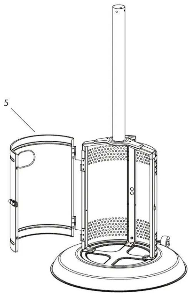
STEP 4 - ATTACHING THE CYLINDER CHAMBER DOOR
- Hang the cylinder chamber door (5) on the hinges.
- Ensure that the alignment is correct and tighten all bolts securely.
natural_image
Technical line drawing of a portable air purifier with a cylindrical top and circular base (no text or symbols)STEP 5 - ATTACHING THE CYLINDER CHAMBER TOP
- Slide the cylinder chamber top (6) down over the lower support pole (3) as shown and secure to the cylinder chamber supports (2), using three bolts (CC) and three nuts (BB).

STEP 6 - ATTACHING THE PARASOL SUPPORTS
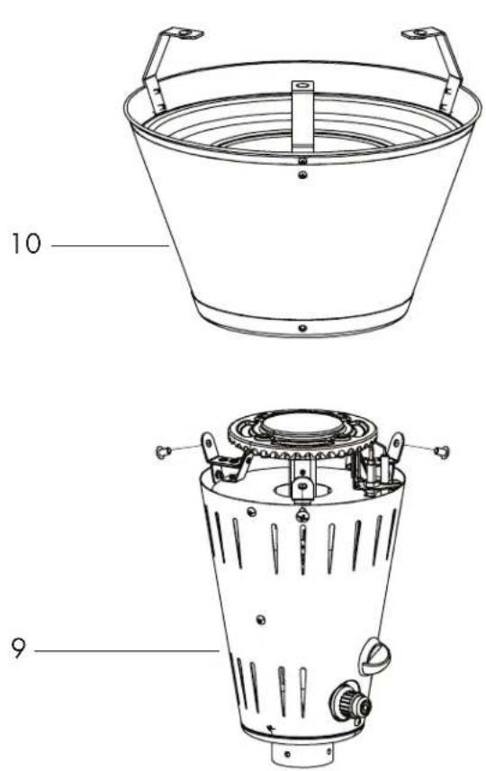
- Attach the three parasol supports (11) to the burner mesh (10) using six of the pre-fitted bolts.

STEP 7 - ASSEMBLING THE LANTERN
- Lower the burner mesh (10) onto the main burner (9) and secure with three of the pre-fitted bolts.
STEP 8 - ATTACHING THE LANTERN
- Feed the hose down through the upper support pole (8) and secure the assembled lantern to the upper support pole (8) using four bolts (CC), washers (DD) and spring washers (GG).
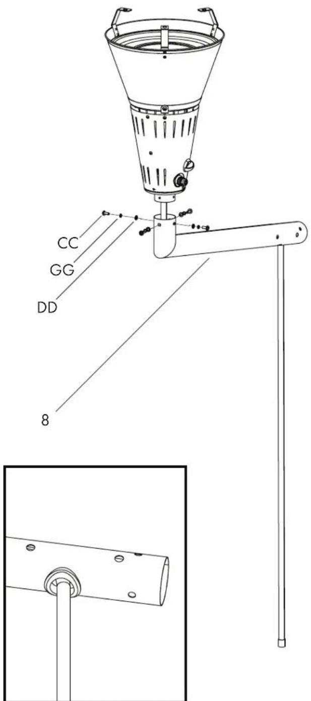
NOTE: Make sure the rubber siding is in place. If it is not, please call Customer Service.
ASSEMBLY INSTRUCTIONS
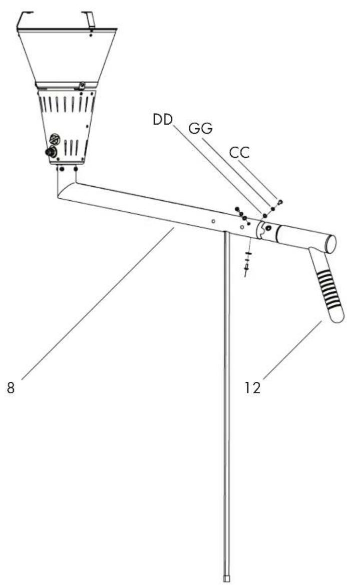
STEP 9 - ATTACHING THE HANDLE
- Attach the handle (12) to the upper support pole (8) using three bolts (CC), washers (DD) and spring washers (GG).
STEP 10 - ATTACHING THE SWIVEL HEAD
- Attach the swivel head (7) to the upper arm assembly using the pre-fitted bolt, as shown below.

natural_image
Technical line drawing of a mechanical device with labeled component '7' (no text or symbols beyond label)STEP 11 - ASSEMBLING THE UPPER SECTION
- Feed the hose down through the lower support pole (3) and lower the upper arm assembly, attaching the swivel head (7) to the lower support pole (3) using four bolts (CC), washers (DD) and spring washers (GG). The arrow markings must be aligned for this step. Keep the upper arm assembly folded down as shown below.

STEP 12 - ATTACHING THE REGULATOR AND PROPANE BOTTLE
NOTE: THE CYLINDER MUST BE POSITIONED AS SHOWN IN THE PATIO HEATER CYLINDER CHAMBER TO PROVIDE VAPOR WITHDRAWAL.
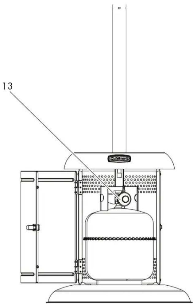
- Connect the lantern and hose assembly to the regulator (13) and secure tightly with the adjustable wrenches.
- Screw the regulator (13) onto the gas cylinder (turn clockwise to tighten it securely).
- Position the gas cylinder inside the cylinder chamber as shown securing with the chain.
• Perform a Leak Test (see page 19).
STEP 13 - ASSEMBLING THE REFLECTOR
WARNING: While every precaution has been made in the manufacture of this product, care must be taken during assembly in case sharp edges are present.
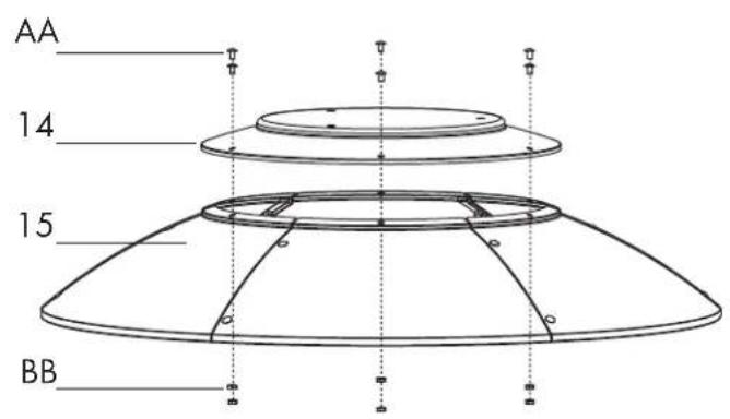
- Loosely screw the side panels (15) together using twelve bolts (AA) and nuts (BB), overlapping as shown below.
- Attach the top panel (14) to the top of the assembled side panels (15) using six bolts (AA) and nuts (BB), and then fully tighten all bolts.

STEP 14 - ATTACHING THE REFLECTOR TO THE LANTERN
- Fit the reflector to the lantern using three bolts (FF) and washers (EE).

ASSEMBLY INSTRUCTIONS
STEP 15 - SECURING THE UPPER SECTION
- Raise the upper arm upwards and secure using the pre-fitted pin.

natural_image
Line drawing of a portable air conditioner with a spherical top and base (no text or symbols)STEP 16 - FITTING THE BATTERY
- Unscrew sparker button (A) and insert battery (B), positive side facing outwards.

- Beware of the pinch point between the burner arm (horizontal rod) and the vertical pole, when lowering and raising the head (Fig.1).
- Certain materials or items, when stored under the heater, will be subjected to radiant heat and could be seriously damaged.
- Inspect the visible portion of the hose before each use of the appliance. The hose inside cylinder pole housing should be checked annually and a leak test should be performed when re-assembled.
- Children and adults should be alerted to the hazards of high surface temperatures and should stay away to avoid burns or clothing ignition.
- Young children should be carefully supervised when they are in the area of the heater.
- Clothing or other flammable materials should not be hung from the heater, or placed on or near the heater.
- Any guard or other protective device removed for servicing the heater must be replaced prior to operating the heater.
- Installation and repair should be done by a qualified service person. The heater should be inspected before use and at least annually by a qualified service person.
- More frequent cleaning may be required as necessary. It is imperative that the control compartment, burners and circulating air passageways of the heater be kept clean.
- Keep the appliance area clear and free from combustible materials, gasoline and other flammable vapors and liquids.
- Do not obstruct the flow of combustion and ventilation air.
- Keep the ventilation openings of the cylinder enclosure free and clear from debris.
- The propane-gas supply cylinder to be used must be: a. Constructed and marked in accordance with the specifications for propane-gas cylinders of the U.S. Department of Transportation (DOT); or the Standard for cylinders, Spheres and Tubes for Transportation of Dangerous Goods and Commission, CAN/CSA-B339, as
applicable; b. Provided with a listed overfilling prevention device; and c. Provided
with a cylinder connection device compatible with the connection for the appliance. d. 20 lb (9 kg) cylinder. LPG capacity 4.7 gallons (17.8 litres). Cylinder Dimensions: Height 17.75 in. (451 mm) and width 12.25 in. (311 mm). The propane gas cylinder used must include a collar to protect the cylinder valve.
- A cylinder must be stored outdoors in a well-ventilated area out of reach of children. A disconnected cylinder must have dust caps tightly installed and must not be stored in a building, garage or any enclosed area. The pressure regulator and hose supplied must be used and any replacement pressure regulator or hose must be those as specified by the manufacturer.
- Do not store spare propane-gas cylinder under or near this appliance.
- Never fill the cylinder beyond 80% full; and for appliances designed to use a CGA No. 791 connection, place the dust cap on the cylinder valve outlet whenever the cylinder is not in use. Only install the type of dust cap on the cylinder valve that is provided with the cylinder valve. Other types of caps or plugs may result in leakage of propane.
POSITIONING INSTRUCTIONS
- This appliance is for OUTDOOR USE ONLY and should be placed in a well ventilated area.
- A well ventilated area must have a minimum of 30% of its surface area open. (Surface area is defined as the total surface of the walls.)
- The sides of the appliance should NEVER be closer than 40 in. (1 m) from any combustible surface.
- This appliance is for OUTDOOR USE ONLY and should be placed in a well ventilated area. - A well ventilated area must have a minimum of 30% of its surface area open. (Surface area is defined as the total surface of the walls.) - The sides of the appliance should NEVER be closer than 40 in. (1 m) from any combustible surface.

natural_image
Technical line drawing of a mechanical device with a circular component and lever mechanism (no text or symbols)

- Keep this appliance away from any flammable materials!
- Important - Make sure the propane tank is placed level within the base.
- Should you need to change the gas bottle, confirm the gas supply is turned off at the regulator or bottle / cylinder valve, and there are no sources of ignition (cigarettes, open flame, sparks, etc.) near before proceeding.
- Inspect the gas hose to ensure it is free from any twisting or tension. The hose should hang freely with no bends, folds, or kinks that could obstruct free flow of gas. Always inspect the hose for cuts, cracks, or excessive wear before use. If the hose is damaged, it must be replaced with a hose suitable for use with propane gas.
CONNECTING TO THE CYLINDER
- Confirm all control knobs are in the off position.
- Connect the regulator to the gas bottle according to your regulator and bottle dealer instructions.
USE INSTRUCTIONS
- Before proceeding, make sure you understand the warnings section of this manual.
- This patio heater shall be used only in a well ventilated space and shall not be used in a building, garage or any other enclosed area.
- This patio heater may be installed in shelter no more inclusive than; with walls on all sides but with no overhead cover, within a partial enclosure that includes an overhead cover and no more than two side walls (these side walls may be parallel, as in a breezeway or at right angles to each other), within a partial enclosure which includes an overhead cover and three side walls, as long as 30% or more of the horizontal periphery of the enclosure is permanently open.
ROTATING THE BURNER HEAD
natural_image
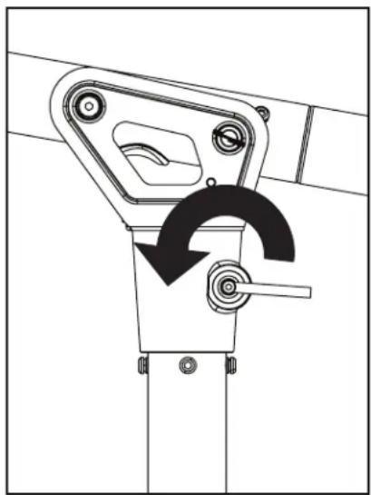
Mechanical lever mechanism diagram showing a rotating lever and adjustment knob (no text or symbols)Rotate the swivel lock in an anti-clockwise direction to release the rotation bracket.
natural_image
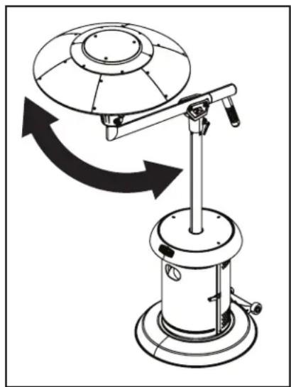
Technical line drawing of a mechanical device with rotating components and directional arrows indicating motion (no text or symbols)Rotate the burner head to your desired position.

natural_image
Mechanical linkage mechanism diagram showing a curved arrow indicating rotational motion (no text or symbols)Rotate the swivel lock in a clockwise direction to tighten the rotation bracket and lock into position.
RAISING AND LOWERING THE BURNER HEAD
natural_image
Technical line drawing of a mechanical device with a circular base and vertical support (no text or symbols)To fold the burner head down, position the lantern opposite the wheels as shown above.

natural_image
Technical line drawing of a mechanical bracket or clamp assembly (no text or symbols)Ensure that the swivel lock is in the lock position.

natural_image
Technical line drawing of a mechanical clamp or bracket assembly (no text or symbols)Remove the lock pin and gently lower down the burner head.

natural_image
Technical line drawing of a mechanical clamp or bracket assembly (no text or symbols)Put the lock pin back into position.
Note: When storing the patio heater, ensure that it is in the folded down position.
BEFORE LIGHTING
- Inspect the visible portion of the hose before each use of the appliance.
- Inspect the entire hose assembly at least annually. If disassembly is required, perform a leak test to check the connections upon re-assembly. Inspect the portion of the hose that is not visible. The hose assembly must be replaced prior to the appliance being put into operation.
- Replace the hose if there is evidence of excessive abrasion or wear, or if the hose is damaged. The replacement hose assembly shall be that specified by the manufacturer.
LIGHTING INSTRUCTIONS
• Fit battery to sparker (see Fig. 2).
- Turn on the gas supply at the cylinder.
- Push the dial in and turn to position
- While the dial is held pressed in at position, press the spark button to ignite the heater.
- Hold the dial in for at least 10 seconds to ensure the heater stays lit.
- If the heater does not light after holding in the dial in for 20 seconds wait 5 minutes and try again. Do not continuously hold the dial in as you may cause a build up of gas.
- In windy conditions, shield from wind to ensure easy lighting and hold the dial in for at least 20 seconds to ensure the heater stays lit.
- Turn the control dial to high or low flame position as required. Correct operation of the heater is indicated by a predominantly blue, quiet flame.
- If the sparker fails, you can light your patio heater using a match. To light your patio heater with a match: 1. Place the lit match through the gap below the burner mesh and wind guard. 2. Turn the control dial to the position. After the burner ignites, keep the control dial held in for 10 seconds to ensure the burner stays lit and then release. 3. If the burner does not light after holding the control dial in for 20 seconds with the lit match in position, remove the match, turn the control dial to the off position, wait 5 minutes and then repeat.
TO TURN OFF
- Push the dial in and turn to position .
- Turn the gas off and disconnect at the cylinder when not in use.
- Remove battery from ignition unit during prolonged periods of non-use.
LEAK TESTING
Although all gas connections on the heater are leak tested prior to shipment, a complete gas tightness check must be performed at the installation site due to possible shifts during shipment, installation or excessive pressure unknowingly being applied to the unit. Periodically check the whole system for leaks and immediately check the system if the smell of gas is detected. To check the connection at the gas hose/regulator/cylinder:
- Ensure you are in a well ventilated area.
- Confirm all control knobs are set to the "OFF" position.
- Turn ON LP gas tank at valve.
- Check for leaks by brushing a solution of 50% water and 50% dish soap at all "X" locations (see Fig. 3).
- NEVER USE AN OPEN FLAME to test for leaks at any time.
- Check each place for growing bubbles. If "growing" bubbles appear, turn the Tank Valve off and DO NOT use your heater until the leak is repaired.


natural_image
Pure mechanical diagram showing a valve or actuator without any text, numbers, or symbolsFig. 3
- A slight leak could cause a fire.
- If no bubbles appear after one minute, turn the tank OFF, wash off soapy solution with cold water and towel dry.
- Leak test annually and whenever the gas bottle is removed or replaced.
WARNING: When leak testing this appliance, make sure to test and tighten all loose connections. A slight leak in the system can result in a low flame or hazardous condition. Most L.P. gas tanks now come equipped with a leak detector mechanism internal to the tank. When gas is allowed to escape rapidly, it shuts of the gas supply. A leak may significantly reduce the gas flow, making the heater difficult to light or cause low flames.
GAS AND REGULATOR
- The gas hose must be connected in accordance with these instructions. When installed correctly all parts of the hose should be contained within the patio heater pole and gas cylinder chamber. No part of the hose should be outside of the patio heater body where it could be a trip hazard or could be accidentally damaged.
• This appliance is for propane use only.
• See instructions supplied with the regulator for correct use and attachment.
• Gas bottles should never be stored on their sides. - Never store gas bottles indoors.
- This appliance is supplied with a propane regulator which must only be used for propane gas.
- NEVER use an adjustable regulator with this appliance.
- Please consult your gas dealer for the most suitable gas bottles for your regulator.
FLAME CHARACTERISTIC
- The flame pattern at the burner mesh should be visually checked whenever the heater is operated.
- Normally, the burner flame is blue with yellow flame at the top. The burner mesh will become red hot.
- If flames extend beyond the surface of the burner mesh, or there is the phenomena of flame lift or light back, or a black spot is accumulating on the burner mesh or reflector, the heater should be turned off immediately.
- The heater should not be operated again until the unit is serviced or repaired.

Yellow tip
Primary blue flame
SCREW AND BOLT CONNECTIONS
- All screws and bolts, etc., should be checked and tightened on a regular basis.
STORAGE
- Do not leave the patio heater exposed to outside weather conditions or stored in damp moist conditions.
- To save space during long-term storage, the reflector can be removed. Take care to ensure the shape of the reflector is not damaged or deformed, as this will affect performance.
- Storage of an appliance indoors is permissible only if the cylinder is disconnected and removed from the appliance.
- When using the heater after extended periods of storage, re-attach the reflector.
- The heater should never be operated without the reflector in place.
- If the heater is to be stored indoors, the gas bottle must be disconnected and left outside in a dry, well-ventilated area, away from any sources of heat or ignition.
- Do not let children tamper with the bottle.
SERVICE
- We recommend that servicing of this appliance should be performed either after every 100 hours of use or annually, whichever is achieved soonest.
- If your heater needs maintenance or is not working properly, please contact your local authorized agent for service.
- It is a necessity to contact an authorized source for replacement of parts and/or servicing.
- This work must be carried out by a qualified gas technician.
- Spare parts may be obtained by contacting Customer Service at 1-866-994-6390. Manufactured by Universal Innovations. Kilcoole Industrial Estate, Kilcoole, Co. Wicklow, Ireland.
CARE & CLEANING
- Regularly clean your patio heater between uses and especially after extended periods of storage.
- Ensure the heater control is turned fully to the off position, the gas supply is shut off at the regulator or bottle / cylinder valve, and the heater and its components are sufficiently cool before cleaning.
- Never douse the heater with water when its surfaces are hot.
- In the event that the rotation mechanism is not moving freely, apply a small amount of 3-in-1 lubricant to the joints of the rotation mechanism.

Intertek
5010527
EXPLODED VIEWS

PARTS LIST
| PART | DESCRIPTION |
| S60059 | Base |
| S60060 | Cylinder Chamber Support A |
| S60061 | Cylinder Chamber Support B |
| S60062 | Cylinder Chamber Support C |
| S60063 | Lower Support Pole |
| S60064 | Cylinder Chamber Wall |
| S60065 | Cylinder Chamber Door |
| S60066 | Cylinder Chamber Top |
| S60067 | Swivel Head |
| S60068 | Upper Support Pole |
| S60069 | Main Burner and Hose |
| S60070 | Burner Mesh |
| S60071 | Parasol Supports |
| PART | DESCRIPTION |
| S60072 | Handle |
| S60073 | Regulator |
| S60074 | Top Panel (Dome) |
| S60075 | Side Panels (6) |
| S60076 | Lock Pin |
| S60077 | Swivel Bolt |
| S60078 | Wheel Set |
| S60079 | Thermocouple / Tiltswitch Assembly |
| S60080 | Hose |
| S60081 | Control Knob (Burner) |
| S60082 | Ignitor Button / Battery Contact |
| S60083 | Hardware Parts Pack |
WARRANTY AND REPLACEMENT PARTS
WARRANTY
• PROOF OF PURCHASE is required to access this warranty program, which is in effect from the date of purchase.
- Customers will be subject to parts, shipping, and handling fees if unable to provide proof of the purchase or after the warranty has expired.
- If you have any questions or problems, you can call our customer service department at 1-866-994-6390 from 9:00am to 5:00pm Eastern time, Monday through Friday for assistance.
- This limited warranty applies to the functionality of the product ONLY and does not cover cosmetic issues such as scratches, dents, corrosion or discoloring by heat, abrasive and chemical cleaners or any tools used in the assembly or installation of the appliance, surface rust, or the discoloration of stainless steel surfaces. Paint is not warranted and will require touch up. RUST is not considered a manufacturing or materials defect.
- This limited warranty will not reimburse you for the cost of any inconvenience, food, personal injury or property damage.
LIMITED WARRANTY
- All parts warranted one-year from date of purchase.
WARRANTY PROVISIONS
- This warranty is non-transferable and does not cover failures due to misuse of improper installation or maintenance.
- This warranty is for replacement of defective parts only. We are not responsible for incidental or consequential damages or labor costs.
- This warranty does not cover corrosion or discoloration after the appliance is used, or lack of maintenance, hostile environments, accidents, alterations, abuse or neglect.
- This warranty does not cover damage caused by heat, abrasive and chemical cleaners, or any damage to other components used in the installation or operation of the patio heater.
- Paint is not warranted and may require touch-up.
DISCLAIMER OF IMPLIED WARRANTIES; LIMITATION OF REMEDIES
- Repair or replacement of defective parts is your exclusive remedy under the terms of this limited warranty.
- Manufacturer will not be responsible for any consequential or incidental damages caused by weather. This limited warranty or any applicable implied warranty does not cover damage resulting from acts of God, improper care and maintenance, grease fire, accident, alteration, replacement of parts by anyone other than manufacturer, misuse, transportation, commercial use, hostile environments (inclement weather, act of nature, animal tampering), improper installation not in accordance with local codes or printed manufacturer instructions.
- Due to extremely high temperatures, discoloration of the burner occur and is considered normal. Stainless steel has an increased resistance to rust; it is not rust proof. Prolonged exposure to moisture may result in increased staining and/or rusting. Due to extremely high temperatures inside, the patio heater may show signs of staining/rust. This is normal and will not affect normal use.
• To register your Cuisinart product, please visit https://cuisinart.registria.com. - For FAQ's and replacement parts, please contact us at grilling@thefulhamgroup.com. For our consumer care department, please contact us at consumercare@thefulhamgroup.com or call 1-866-994-6390 from 9:00am to 5:00pm Eastern time, Monday through Friday.
Get Social With Us @CuisinartBBQ


See our full line of premium Cuisinart® Outdoor Cooking Products at www.cuisinart.com/outdoorgrilling
©2021 Cuisinart
Cuisinart® is a registered trademark under license to The Fulham Group.
Distributed by The Fulham Group, Newton, MA. 02466 U.S.A.
Model # COH-400
North American Distributor:
The Fulham Group
Newton, MA 02466

SAVOR THE GOOD LIFE
- DANGER
- WARNING
- WARNING: For Outdoor Use Only.
- CARBON MONOXIDE HAZARD
- Customer Service Hotline
- 1-866-994-6390
- DO NOT RETURN PRODUCT
- TO THE STORE
- CALIFORNIA PROPOSITION 65 WARNING:
- IMPORTANT: ALL INSTRUCTIONS AND SAFEGUARDS ON THIS SECTION MUST BE FOLLOWED TO PREVENT DAMAGE AND/OR INJURY.
- USE CAUTION AND COMMON SENSE WHEN USING YOUR OUTDOOR PATIO HEATER. FAILURE TO ADHERE TO THE SAFETY WARNING AND GUIDELINES IN THE MANUAL COULD RESULT IN BODILY INJURY OR PROPERTY DAMAGE. SAVE THIS MANUAL FOR FUTURE REFERENCE.
- SAFETY INFORMATION
- TABLE OF CONTENTS
- EXPLODED VIEW
- COMPONENTS
- HARDWARE INCLUDED
- PLANNING ASSEMBLY
- TOOLS REQUIRED
- STEP 1 - ASSEMBLING THE LEGS
- STEP 2 - ATTACHING THE LOWER SUPPORT POLE
- ASSEMBLY INSTRUCTIONS
- STEP 3 - ATTACHING THE CYLINDER CHAMBER WALL
- STEP 4 - ATTACHING THE CYLINDER CHAMBER DOOR
- STEP 5 - ATTACHING THE CYLINDER CHAMBER TOP
- STEP 6 - ATTACHING THE PARASOL SUPPORTS
- STEP 7 - ASSEMBLING THE LANTERN
- STEP 8 - ATTACHING THE LANTERN
- STEP 9 - ATTACHING THE HANDLE
- STEP 10 - ATTACHING THE SWIVEL HEAD
- STEP 11 - ASSEMBLING THE UPPER SECTION
- STEP 12 - ATTACHING THE REGULATOR AND PROPANE BOTTLE
- STEP 13 - ASSEMBLING THE REFLECTOR
- STEP 14 - ATTACHING THE REFLECTOR TO THE LANTERN
- STEP 15 - SECURING THE UPPER SECTION
- STEP 16 - FITTING THE BATTERY
- POSITIONING INSTRUCTIONS
- CONNECTING TO THE CYLINDER
- USE INSTRUCTIONS
- RAISING AND LOWERING THE BURNER HEAD
- BEFORE LIGHTING
- LIGHTING INSTRUCTIONS
- TO TURN OFF
- LEAK TESTING
- GAS AND REGULATOR
- FLAME CHARACTERISTIC
- SCREW AND BOLT CONNECTIONS
- STORAGE
- SERVICE
- CARE & CLEANING
- EXPLODED VIEWS
- PARTS LIST
- WARRANTY AND REPLACEMENT PARTS
- WARRANTY
- LIMITED WARRANTY
- WARRANTY PROVISIONS
- DISCLAIMER OF IMPLIED WARRANTIES; LIMITATION OF REMEDIES
Brand : CUISINART
Model : Perfect Position COH-400
Category : Heating